

Page 1
• 1000 Series Twin Straight Tube Coriolis Mass Flowmeter
• 2000 Series Twin Straight Tube Coriolis Ma
ss Flowmeter
• 3000 Series Single Z Tube Coriolis Mass Flowmeter
• 7000 Series Single Straight Tube Co
riolis Mass Flowmeter
• 8000/9000 Series Twin U Tube Coriolis Mass Flowmeter
OPTIMASS
Handbook
r
s
Page 2

2
Page 3

3
CONTENTS
1. Safety Instructions
1.1 Intended Use . . . . . . . . . . . . . . . . . . . . . . . . . . . . . . . . . . . . . . . . . . . . . . . . . . . . . . . . . . . . . .6
1.2 CE/EMC Standards/Approvals . . . . . . . . . . . . . . . . . . . . . . . . . . . . . . . . . . . . . . . . . . . . . . .6
1.3 PED Integrity . . . . . . . . . . . . . . . . . . . . . . . . . . . . . . . . . . . . . . . . . . . . . . . . . . . . . . . . . . . . .6
1.4 Secondary Containment & Burst Discs . . . . . . . . . . . . . . . . . . . . . . . . . . . . . . . . . . . . . . . .6
1.5 Explanation of Symbols Used . . . . . . . . . . . . . . . . . . . . . . . . . . . . . . . . . . . . . . . . . . . . . . .7
2. Instrument Description
2.1. Scope of Delivery . . . . . . . . . . . . . . . . . . . . . . . . . . . . . . . . . . . . . . . . . . . . . . . . . . . . . . . . .8
2.1.1 Flanged Versions . . . . . . . . . . . . . . . . . . . . . . . . . . . . . . . . . . . . . . . . . . . . . . . . . . .8
2.1.2 Hygienic Versions . . . . . . . . . . . . . . . . . . . . . . . . . . . . . . . . . . . . . . . . . . . . . . . . . . .8
2.1.3 Remote Field/Wall Converter . . . . . . . . . . . . . . . . . . . . . . . . . . . . . . . . . . . . . . . . .8
3. Installation Guidance
3.1 General Installation Information . . . . . . . . . . . . . . . . . . . . . . . . . . . . . . . . . . . . . . . . . . . . .9
3.2 General Installation Principles . . . . . . . . . . . . . . . . . . . . . . . . . . . . . . . . . . . . . . . . . . . . . .10
3.3 Storage . . . . . . . . . . . . . . . . . . . . . . . . . . . . . . . . . . . . . . . . . . . . . . . . . . . . . . . . . . . . . . . . . .10
OPTIMASS
3.4 Lifting . . . . . . . . . . . . . . . . . . . . . . . . . . . . . . . . . . . . . . . . . . . . . . . . . . . . . . . . . . . . . . . . . . .10
3.5 CSA Dual Seal . . . . . . . . . . . . . . . . . . . . . . . . . . . . . . . . . . . . . . . . . . . . . . . . . . . . . . . . . . . . .10
4. OPTIMASS 1000 (Twin Straight Tube Meter)
4.1 Specific Installation Guidelines . . . . . . . . . . . . . . . . . . . . . . . . . . . . . . . . . . . . . . . . . . . . . .12
4.2 Ambient/Prcocess Temperatures . . . . . . . . . . . . . . . . . . . . . . . . . . . . . . . . . . . . . . . . . . . .12
4.3 Pressure Equipment Directive . . . . . . . . . . . . . . . . . . . . . . . . . . . . . . . . . . . . . . . . . . . . . . .12
4.4 Secondary Pressure Containment . . . . . . . . . . . . . . . . . . . . . . . . . . . . . . . . . . . . . . . . . . . .13
4.5 Hygienic Applications . . . . . . . . . . . . . . . . . . . . . . . . . . . . . . . . . . . . . . . . . . . . . . . . . . . . . .13
4.6 Pressure Ratings . . . . . . . . . . . . . . . . . . . . . . . . . . . . . . . . . . . . . . . . . . . . . . . . . . . . . . . . . .14
4.7 Heating and Insulation . . . . . . . . . . . . . . . . . . . . . . . . . . . . . . . . . . . . . . . . . . . . . . . . . . . . .16
4.8 Purge Ports & Burst Discs . . . . . . . . . . . . . . . . . . . . . . . . . . . . . . . . . . . . . . . . . . . . . . . . . .18
4.9 Technical Data . . . . . . . . . . . . . . . . . . . . . . . . . . . . . . . . . . . . . . . . . . . . . . . . . . . . . . . . . . . .18
5. OPTIMASS 2000 (Twin Straight Tube Meter)
5.1 Specific Installation Guidelines . . . . . . . . . . . . . . . . . . . . . . . . . . . . . . . . . . . . . . . . . . . . . .25
5.2 Ambient/Process Temperatures . . . . . . . . . . . . . . . . . . . . . . . . . . . . . . . . . . . . . . . . . . . . .25
5.3 Pressure Equipment Directive . . . . . . . . . . . . . . . . . . . . . . . . . . . . . . . . . . . . . . . . . . . . . . .25
5.4 Secondary Pressure Containment . . . . . . . . . . . . . . . . . . . . . . . . . . . . . . . . . . . . . . . . . . . .26
5.5 Hygienic Applications . . . . . . . . . . . . . . . . . . . . . . . . . . . . . . . . . . . . . . . . . . . . . . . . . . . . . .26
5.6 Pressure Ratings . . . . . . . . . . . . . . . . . . . . . . . . . . . . . . . . . . . . . . . . . . . . . . . . . . . . . . . . . .27
5.7 Heating and Insulation . . . . . . . . . . . . . . . . . . . . . . . . . . . . . . . . . . . . . . . . . . . . . . . . . . . . .29
5.8 Purge Ports & Burst Discs . . . . . . . . . . . . . . . . . . . . . . . . . . . . . . . . . . . . . . . . . . . . . . . . . .32
5.9 Technical Data . . . . . . . . . . . . . . . . . . . . . . . . . . . . . . . . . . . . . . . . . . . . . . . . . . . . . . . . . . . .32
6. OPTIMASS 3000 (Single Z Shaped Tube Meter)
6.1 Specific Installation Guidelines . . . . . . . . . . . . . . . . . . . . . . . . . . . . . . . . . . . . . . . . . . . . . .37
6.2 Ambient/Process Temperatures . . . . . . . . . . . . . . . . . . . . . . . . . . . . . . . . . . . . . . . . . . . . .38
Page 4

4
6.3 Pressure Equipment Directive . . . . . . . . . . . . . . . . . . . . . . . . . . . . . . . . . . . . . . . . . . . . . . .38
6.4 Secondary Pressure Containment . . . . . . . . . . . . . . . . . . . . . . . . . . . . . . . . . . . . . . . . . . . .39
6.5 Pressure Ratings . . . . . . . . . . . . . . . . . . . . . . . . . . . . . . . . . . . . . . . . . . . . . . . . . . . . . . . . .39
6.6 Heating & Insulation . . . . . . . . . . . . . . . . . . . . . . . . . . . . . . . . . . . . . . . . . . . . . . . . . . . . . . .41
6.7 Purge Port Meters & Burst Discs . . . . . . . . . . . . . . . . . . . . . . . . . . . . . . . . . . . . . . . . . . . .42
6.8 Technical Data . . . . . . . . . . . . . . . . . . . . . . . . . . . . . . . . . . . . . . . . . . . . . . . . . . . . . . . . . . . .43
7. OPTIMASS 7000 (Single Straight Tube Meter)
7.1 Specific Installation Guidelines . . . . . . . . . . . . . . . . . . . . . . . . . . . . . . . . . . . . . . . . . . . . . .46
7.2 Ambient/Process Temperatures . . . . . . . . . . . . . . . . . . . . . . . . . . . . . . . . . . . . . . . . . . . . .46
7.3 Pressure Equipment Directive . . . . . . . . . . . . . . . . . . . . . . . . . . . . . . . . . . . . . . . . . . . . . . .46
7.4 Secondary Pressure Containment . . . . . . . . . . . . . . . . . . . . . . . . . . . . . . . . . . . . . . . . . . . .47
7.5 Hygienic Applications . . . . . . . . . . . . . . . . . . . . . . . . . . . . . . . . . . . . . . . . . . . . . . . . . . . . . .47
7.6 Pressure Ratings . . . . . . . . . . . . . . . . . . . . . . . . . . . . . . . . . . . . . . . . . . . . . . . . . . . . . . . . . .48
7.7 Heating and Insulation . . . . . . . . . . . . . . . . . . . . . . . . . . . . . . . . . . . . . . . . . . . . . . . . . . . . .52
7.8 Purge Port and Burst Discs . . . . . . . . . . . . . . . . . . . . . . . . . . . . . . . . . . . . . . . . . . . . . . . . .56
7.9 Technical Data . . . . . . . . . . . . . . . . . . . . . . . . . . . . . . . . . . . . . . . . . . . . . . . . . . . . . . . . . . . .56
8. OPTIMASS 8000/9000 (Twin U Tube Meter)
8.1 Specific Installation Guidlines . . . . . . . . . . . . . . . . . . . . . . . . . . . . . . . . . . . . . . . . . . . . . . .62
8.2 Ambient/Process Temperatures . . . . . . . . . . . . . . . . . . . . . . . . . . . . . . . . . . . . . . . . . . . . .62
8.3 Pressure Equipment Directive . . . . . . . . . . . . . . . . . . . . . . . . . . . . . . . . . . . . . . . . . . . . . . .63
8.4 Secondary Pressure Containment . . . . . . . . . . . . . . . . . . . . . . . . . . . . . . . . . . . . . . . . . . . .63
8.5 Pressure De-rating . . . . . . . . . . . . . . . . . . . . . . . . . . . . . . . . . . . . . . . . . . . . . . . . . . . . . . . .63
8.6 Hygienic and Sanitary Connections . . . . . . . . . . . . . . . . . . . . . . . . . . . . . . . . . . . . . . . . . . .66
8.7 Heating and Insulation . . . . . . . . . . . . . . . . . . . . . . . . . . . . . . . . . . . . . . . . . . . . . . . . . . . . .67
8.8 Purge Ports and Burst Discs . . . . . . . . . . . . . . . . . . . . . . . . . . . . . . . . . . . . . . . . . . . . . . . .69
8.9 Technical Data . . . . . . . . . . . . . . . . . . . . . . . . . . . . . . . . . . . . . . . . . . . . . . . . . . . . . . . . . . . .70
9. MFC 300 Converter
9.1 Electrical Connections . . . . . . . . . . . . . . . . . . . . . . . . . . . . . . . . . . . . . . . . . . . . . . . . . . . . . .73
9.2 Mounting MFC 300W . . . . . . . . . . . . . . . . . . . . . . . . . . . . . . . . . . . . . . . . . . . . . . . . . . . . . . .73
9.3 Mounting MFC 300F . . . . . . . . . . . . . . . . . . . . . . . . . . . . . . . . . . . . . . . . . . . . . . . . . . . . . . . .73
9.4 Changing Display Orientation . . . . . . . . . . . . . . . . . . . . . . . . . . . . . . . . . . . . . . . . . . . . . . . .74
9.5 Mains Power Connection versions C, F and W . . . . . . . . . . . . . . . . . . . . . . . . . . . . . . . . . .75
9.6 Connection of Remote Sensors . . . . . . . . . . . . . . . . . . . . . . . . . . . . . . . . . . . . . . . . . . . . . .77
9.6.1 MFC 300F . . . . . . . . . . . . . . . . . . . . . . . . . . . . . . . . . . . . . . . . . . . . . . . . . . . . . . . . .78
9.6.2 MFC 300W . . . . . . . . . . . . . . . . . . . . . . . . . . . . . . . . . . . . . . . . . . . . . . . . . . . . . . . . .78
9.6.3 MFC 300R . . . . . . . . . . . . . . . . . . . . . . . . . . . . . . . . . . . . . . . . . . . . . . . . . . . . . . . . .79
9.7 I/O Assemblies . . . . . . . . . . . . . . . . . . . . . . . . . . . . . . . . . . . . . . . . . . . . . . . . . . . . . . . . . . . .80
9.7.1 Basic I/O . . . . . . . . . . . . . . . . . . . . . . . . . . . . . . . . . . . . . . . . . . . . . . . . . . . . . . . . . .81
9.7.2 Fixed I/O . . . . . . . . . . . . . . . . . . . . . . . . . . . . . . . . . . . . . . . . . . . . . . . . . . . . . . . . . .81
9.7.3 Modular I/O . . . . . . . . . . . . . . . . . . . . . . . . . . . . . . . . . . . . . . . . . . . . . . . . . . . . . . . .81
9.8 Operating Data I/O . . . . . . . . . . . . . . . . . . . . . . . . . . . . . . . . . . . . . . . . . . . . . . . . . . . . . . . .83
9.8.1 Current Output . . . . . . . . . . . . . . . . . . . . . . . . . . . . . . . . . . . . . . . . . . . . . . . . . . . . .83
Page 5

5
9.8.2 Pulse & Frequency Output . . . . . . . . . . . . . . . . . . . . . . . . . . . . . . . . . . . . . . . . . . .84
9.8.3 Status Output and Limit Switches . . . . . . . . . . . . . . . . . . . . . . . . . . . . . . . . . . . . .85
9.8.4 Control Input . . . . . . . . . . . . . . . . . . . . . . . . . . . . . . . . . . . . . . . . . . . . . . . . . . . . . . .86
9.9 Connection Diagrams (Outputs/Inputs) . . . . . . . . . . . . . . . . . . . . . . . . . . . . . . . . . . . . . . . .86
9.9.1 MFC300 W Connection Block . . . . . . . . . . . . . . . . . . . . . . . . . . . . . . . . . . . . . . . . .87
9.9.2 Basic I/O Connection Diagrams . . . . . . . . . . . . . . . . . . . . . . . . . . . . . . . . . . . . . . .87
9.9.3 Modular I/O & BUS I/O Connection Diagrams . . . . . . . . . . . . . . . . . . . . . . . . . . .89
9.9.4 HART . . . . . . . . . . . . . . . . . . . . . . . . . . . . . . . . . . . . . . . . . . . . . . . . . . . . . . . . . . . . .91
9.10 Dimensions and Weights . . . . . . . . . . . . . . . . . . . . . . . . . . . . . . . . . . . . . . . . . . . . . . . . . . .92
9.11 Technical Data . . . . . . . . . . . . . . . . . . . . . . . . . . . . . . . . . . . . . . . . . . . . . . . . . . . . . . . . . . .95
10. Start Up
10.1 Operator Control of the Converter . . . . . . . . . . . . . . . . . . . . . . . . . . . . . . . . . . . . . . . . . . .99
10.2 Time Out Function . . . . . . . . . . . . . . . . . . . . . . . . . . . . . . . . . . . . . . . . . . . . . . . . . . . . . . . .101
10.3 Menu Structure . . . . . . . . . . . . . . . . . . . . . . . . . . . . . . . . . . . . . . . . . . . . . . . . . . . . . . . . . .102
10.4 Table of Settable Functions . . . . . . . . . . . . . . . . . . . . . . . . . . . . . . . . . . . . . . . . . . . . . . . .104
10.5 Description of Functions . . . . . . . . . . . . . . . . . . . . . . . . . . . . . . . . . . . . . . . . . . . . . . . . . . .118
11. Service and Troubleshooting
11.1 Diagnostic Functions . . . . . . . . . . . . . . . . . . . . . . . . . . . . . . . . . . . . . . . . . . . . . . . . . . . . .130
11.2 Functional Tests and Troubleshooting . . . . . . . . . . . . . . . . . . . . . . . . . . . . . . . . . . . . . . .131
11.3 Driver or Sensor Coil . . . . . . . . . . . . . . . . . . . . . . . . . . . . . . . . . . . . . . . . . . . . . . . . . . . . . .133
11.4 Replacing the Sensor or Converter Electronics . . . . . . . . . . . . . . . . . . . . . . . . . . . . . . . .136
11.5 Status Messages and Diagnostics Information . . . . . . . . . . . . . . . . . . . . . . . . . . . . . . . .138
12. Additional Information
12.1 External Standards . . . . . . . . . . . . . . . . . . . . . . . . . . . . . . . . . . . . . . . . . . . . . . . . . . . . . . .142
12.2 Certificates . . . . . . . . . . . . . . . . . . . . . . . . . . . . . . . . . . . . . . . . . . . . . . . . . . . . . . . . . . . . . .142
12.3 Krohne Publications . . . . . . . . . . . . . . . . . . . . . . . . . . . . . . . . . . . . . . . . . . . . . . . . . . . . . .142
12.4 Declaration of Cleanliness Certificate . . . . . . . . . . . . . . . . . . . . . . . . . . . . . . . . . . . . . . . .143
12.5 Specimin Certificate . . . . . . . . . . . . . . . . . . . . . . . . . . . . . . . . . . . . . . . . . . . . . . . . . . . . . .143
Page 6

6
1
SAFETY INSTRUCTIONS
Congratulations on purchasing this high quality product. To get the best out of your mass
flowmeter, please take some time to read through this handbook which describes the many
features and options available. Please refer to the index for a list of detailed topics.
If applicable, a separate document is supplied that describes hazardous area information.
1.1 Intended Use
The OPTIMASS mass flowmeter family is designed for the direct measurement of mass flow
rate, product density and product temperature. Indirectly, it also enables measurement of
parameters such as: total mass; concentration of dissolved substances and the volume flow.
For use in hazardous areas, special codes and regulations are applicable which are specified in
a separate handbook.
Responsibility as to the suitability and intended use of our instruments rests solely with the
purchaser. The supplier does not accept any liability resulting from misuse by the customer.
Improper installation and operation of the flow meters may lead to loss of warranty. Warranty
is also null and void if the instrument is damaged or interfered with in any way.
In addition, the “general conditions of sale” which forms the basis of the purchase agreement
are applicable.
If you need to return your OPTIMASS flow meters to KROHNE, please complete the form on the
last page of this handbook and return it with the meter to be repaired. KROHNE regrets that it
cannot repair or check your flow meter unless accompanied by a completed form.
OPTIMASS
1.2 CE/EMC Standards/Approvals
The OPTIMASS family with the MFC 300/010 signal converter meets all the requirements of the
EU-EMC and PED Directives and bears the CE Symbol.
The OPTIMASS system is approved for hazardous duty installations to the harmonised
European Standards (ATEX) to Factory Mutual (FM) and CSA (Canadian Standards).
Technical data subject to change without notice
It should be noted that this handbook MUST be read in conjunction with the following additional
documentation:
• Hazardous Areas Handbook.
• Communications Handbook.
• Concentration Handbook.
• Corrosion Guidelines.
1.3 PED Integrity
To ensure the PED integrity of the meter, you MUST ensure that the serial numbers on both the
conveter (or remote terminal box) data label and the sensor match.
1.4 Secondary Containment & Burst Discs
Where the meter is being used to measure:
• high pressure gases
• gases kept as liquids by high pressure
and/or where there is a risk of tube failure because of:
• the use of corrosive and/or errosive process fluids
• frequent pressure and/or temperature shocking
• seismic or other shock loading
Krohne strongly recommends that a secondary containment option is purchased. Where the
above situation applies and the process pressure exceeds the secondary pressure containment, Krohne recommends that the burst disc option is also purchased. For more information,
please contact Krohne Ltd
Page 7
7
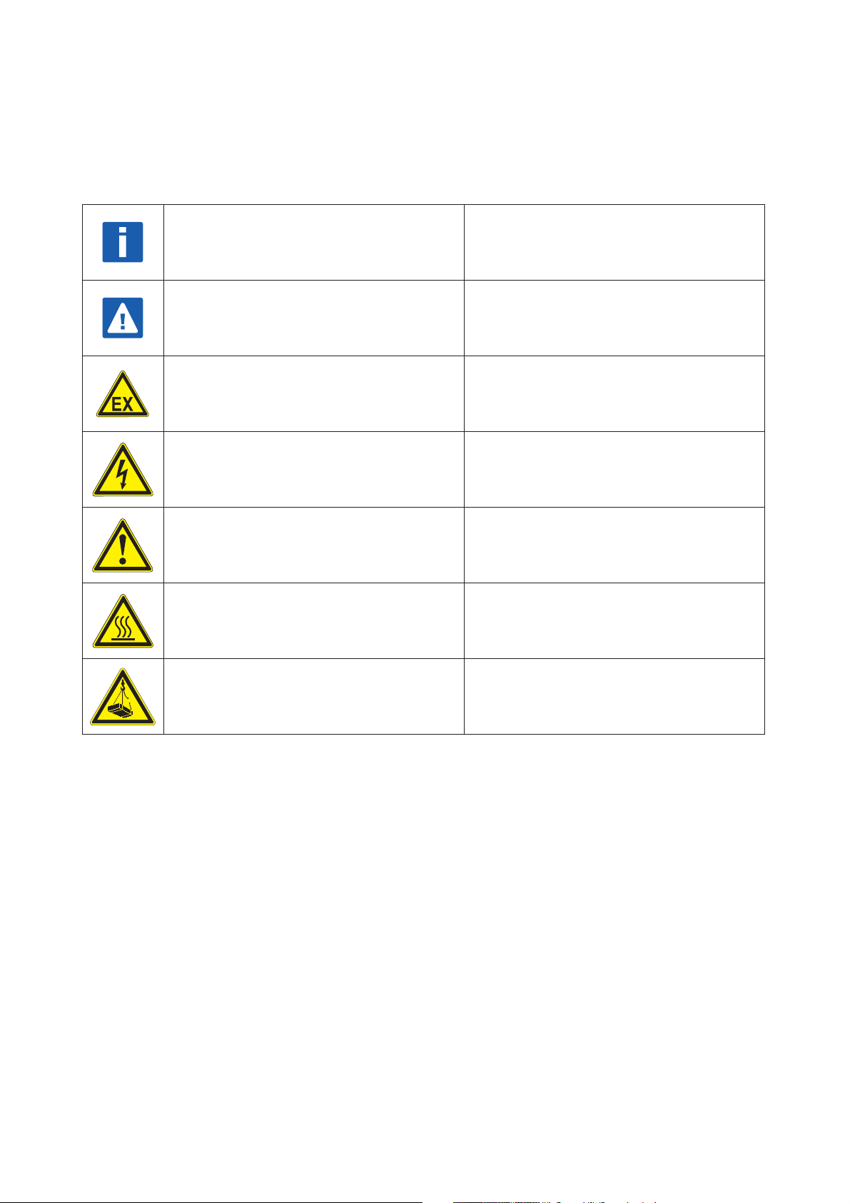
1.5 Explanation of Symbols Used
General Information
General Warning
EX - Hazardous Area Warning
High Voltage
General Hazard
Hot Surface or High Temperature
Heavy Item
The following is a guide to the meaning of the symbols used in this handbook.The symbols fall
into two types. The rectangular symbols with blue background draws the reader’s attention to
general points of information. The triangular symbols with yellow background draw the reader’s attention to hazards or hazardous situations.
Information is important to the
installation/operation of the meter.
Risk of damage to the meter or installation.
Instruction MUST be observed in order to
comply with Hazardous Areas Certification.
Risk of electric shock.
Non specific hazard that could result in injury.
Risk of burning.
Risk of injury.
Page 8

8
2
2.1.1 Flange Versions
2.1.2 Hygienic Versions
2.1.3 Remote Field/Wall/Rack Conveter
Wall Converter
19” Rack Mount Converter
INSTRUMENT DESCRIPTION
2.1 Scope of Delivery
When unpacking your meter, please ensure that no visible damage has occurred during transportation. If damage has occurred, please contact the carrier for claims.
Your high quality instrument has been fully tested and checked before shipping. The following
items should be included with your instrument unless otherwise requested:
1. OPTIMASS Mass Flow Meter
2. Separate Converter with remote converter wall mount (not for compact version)
3. CD-ROM & Quick Start Guides
4. Screw driver for terminal connections
5. Calibration certificate
6. Factory and Material certification, if ordered.
If any of these items are missing, please contact your nearest KROHNE Office or representative
(see back page).
If your meter has been ordered with a flange connection, this will be supplied as per your order
and the flange specification is stamped on the outer edge of the flange.
OPTIMASS
Please check this specification against your original order and refer to the appropriate section
in this handbook.
If your meter was ordered with a hygienic connector, it should be noted that the ‘O’ ring seals
between the meter and process pipework are NOT normally supplied.
If the hygienic connection is via an adaptor, then ‘O’ rings (material EPDM) are supplied in
order to make the connection between the meter and the adaptor. Please note that other
materials are available on request.
‘O’ rings are not normally supplied for the seal between the adaptor connection and process
pipework.
Adaptor connections may also be supplied loose, dependng upon type supplied.
For DIN11864-2 connections, ‘O’ rings and counter flanges are not supplied as standard but
are available on request.
The OPTIMASS range of massflow meters are normally supplied with the converter integrally
fitted. If you have specified a remote converter, the meter will be supplied with the converter
as a separate unit, together with a wall/pipe mounting bracket and a connection box mounted
to the meter.
In order to comply with 3A approval, all unused holes MUST be plugged and unused threads
MUST be covered or removed!
If ordered with the meter, cabling is supplied loose and IS NOT pre-prepared!
If specified at the time of ordering, the meter will be supplied with a plastic wall mounted converter that can be mounted on a wall or a pipe The housing material is Polyamide - polycarbonate.
Please note that the wall converter has not been 3A approved for hygienic applications.
If specified at the time of ordering, the meter will be supplied with a 19” rack mounted converter
Page 9
9
3
INSTALLATION GUIDANCE
3.1 General Installation Information
The OPTIMASS mass flow meters provide high accuracy and excellent repeatability. Narrow
band pass digital filtering, and the mathematically modelled internal primary head design with
AST (Adaptive Sensor Technology) for the OPTIMASS sensor family provide exceptional immunity to external disturbances caused by vibrations from nearby process equipment.
The accuracy of the flow meter is not affected by velocity profile.
The following installation guidelines are practical to implement, particularly if planned before
the OPTIMASS meter is first installed. For further dimensions or connections, please refer to
the relevant section.
For the OPTIMASS, in general, no special mounting requirements are necessary. However,
good general engineering practice for the installation of flow meters should still be observed.
The general guidelines described in this section are valid for the complete OPTIMASS family of
mass flow meters
• The mass flow meters do not require any straight inlet or outlet runs.
• Due to the weight of the meters we recommend the use of supports.
• It is permissible to support the body of the meter.
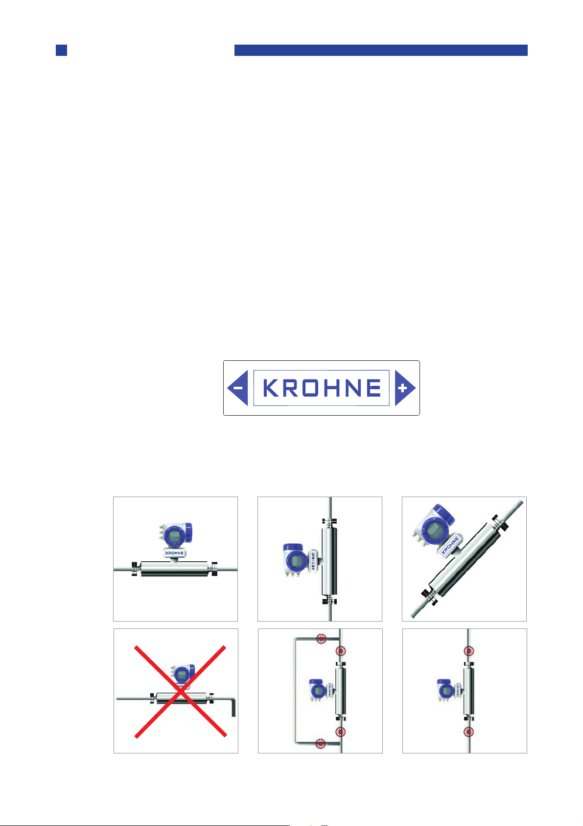
• The meter can be installed horizontally, in an upward sloping pipeline or vertically. For best
results, a vertical installation with flow in an upward direction is recommended.
OPTIMASS
This label on the meter shows the flow direction programmed into the converter in function
C.1.3.1
As default this is always in the direction of the ‘+’ arrow, i.e. left-to right as the label is viewed.
3.2 General Installation Principles
1
456
2
3
Page 10
10
1 Horizontal intalation with flow from left to right
Notes:
NOTE:
OPTIMASS
Liquids
Pressure/Temperature data:
2 Vertcial installation with flow uphill
3 Angled installation with flow uphill
4 Horizontal installation with long vertical drops after the meter ARE NOT recommended
5 6 Vertical installations with isolation valves fitted for setting the zero calibration. It is rec-
ommended that a valve is fitted below the meter to prevent a reverse flow when the
pump is switched off.
Avoid long vertical runs after the meter (4). They can cause siphoning and therefore measurement errors. If long vertical runs are unavoidable, then you should use a valve or orifice plate
downstream of the mter in order to the restrict flow.
Avoid mounting the meter at the highest point in the pipeline. Air or gas can accumulate here
and cause faulty measurements.
3.3 Storage
If the meter is to be stored prior to installation, it is recomended that the meter is stored in its
original packaging and that the ambient temperature range does not exceed -50°C or 85°C
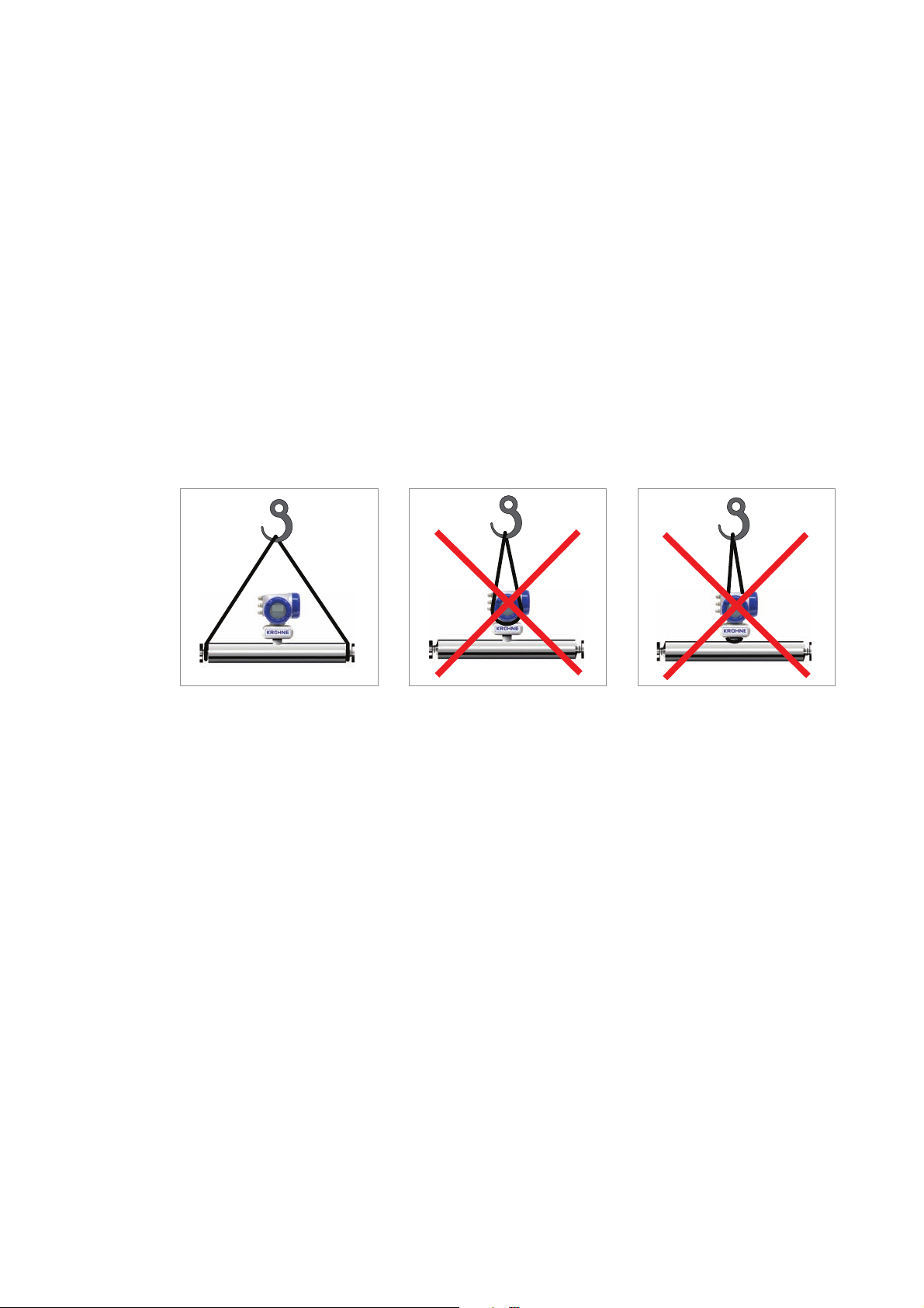
3.4 Lifting
1
1 Use a well maintained sling to lift the meter by the spigots
2 DO NOT lift the meter by the electronics housing.
3 DO NOT lift the meter by the electronics stem.
The 1000 and 2000 meters have 4 eye holes on the outer tube, 2 each end. These can be used
to lift the meter into place on vertical installations, where the meter is supplied with hygienic
connections. Please be aware, that they ARE NOT suitable for lifting the meter where is has
been supplied with [heavier] flange connections. It is the user’s responsibility to use suitable
lifting equipment.
2
3
3.5 CSA Dual Seal
To cover the requirements of ANSI/ISA -12.27.01-2003 “Requirements for Process Sealing
Between Electrical Systems and Flammable or Combustible Process Fluids” a secondary seal
is incorporated into all Optimass/gas products. If the primary seal fails, the secondary seal will
prevent escaping fluid reaching the electronic compartment.
OPTIMASS 1000 / 1300 / 1010 -40°C...130°C and 100...10,000 kPa
OPTIMASS 2000 / 2300 / 2010 -45°C...130°C and 100...14,000 kPa
OPTIMASS 3000 / 3300 / 3010 -40°C...150°C and 100...15,000 kPa
OPTIMASS 7000 / 7300 / 7010 -40°C...150°C and 100...10,000 kPa
1000, 2000, 3000, 7000, 8000, 9000
(Example model code: OPTIMASS 1000C S25 – LIQUID)
Page 11

11
OPTIMASS 8000 / 8300 / 8010 -180°C...230°C and 100 to 26,000 kPa
Meter Status:
Gases
Regular Maintenance of Burst Disc:
OPTIMASS 9000 / 9300 / 9010 0°C...350°C and 100 to 26,000 kPa
If the primary seal fails, the casing of the meter will fill with liquid and the meter will stop
working. The meter will notify the operator by going into <start up> mode and a diagnostic
error will be shown on the MFC300 or PLC display. This is an indication that the primary seal
(tube/s) has failed and the status of the meter should be checked.
The meter will also go into <Start up> mode if the primary seal (tube/s) fail, or are not completely filled with fluid. For example, if the meter is drained or re/filled. To check the status of
the meter, drain and re/fill with fluid and note the MFC300 or PLC display. See section11.5 for a
list of status messages and diagnistics information.
If the meter remains in <Start Up> mode you MUST assume that the primary seal (tube/s) has
failed and the appropriate action MUST be taken.
(Example model code: OPTIMASS 1000C S25 – GAS)
Pressure/Temperature data:
OPTIMASS 1000 / 1300 / 1010 -40°C...130°C and +500 to +10,000 kPa
OPTIMASS 2000 / 2300 / 2010 -45°C...130°C and +500 to +15,000 kPa
OPTIMASS 3000 / 3300 / 3010 -40°C...150°C and +500 to +15,000 kPa
OPTIMASS 7000 / 7300 / 7010 -40°C...150°C and +500 to +10,000 kPa
OPTIMASS 8000 / 8300 / 8010 -180°C...30°Cand +2000 to +26,000 kPa
OPTIMASS 9000 / 9300 / 9010 0°C...350°C and +2000 to +26,000 kPa
Pressures and/or temperatures may be further limited by tube, temperature, connection and
Ex limits. Consult the meter data plates and relevant documentation for full details.
On all meters operating on gas measurement the casing of the meter is fitted with a burst disc.
If the the primary seal (tube/s) fails leakage will occur from the burst disc.
Install the meter so that the burst disc is pointing away from personnel.
Carry out regular maintenance checks on burst discs for leakage and/or blockages.
On all OPTIMASS meters, the primary seal is considered to be the measuring tube of the
meter. The materials of construction of the measuring tube/s are described within the relevant
sections of this handbook and the customer’s product and any other fluid flowing through the
tube must be compatible with the material of construction.
If failure of the primary seal is suspected then the process line should be de-pressurised and
the meter removed as soon as it is safe to do so. Please then contact Krohne customer service
for servicing or replacement of the meter.
Page 12
12
4
Meter Max. Temperature Shift
Measuring tube: Sealing Faces:
Process
Ambient
OPTIMASS 1000
4.1 Specific Installation Guidelines
• Tighten flange bolts evenly.
• Observe the pipe end loads as shown in s. 4.6
• It is permissible to support the weight of the meter on the body.
• Use of standard pipework reducers at the flange is allowed. Avoid extreme changes in pipe
• The use of flexible hoses directly at the meter is permitted.
• The meter can be installed so that the converter is on the side of the meter, resulting in the
• The 1000 series has exceptional immunity to cross-talk, therefore allowing meters to be
4.2 Ambient / Process temperatures
The specified and approved ambient and process temperatures must be observed.
OPTIMASS
size (step changes).
measuring tubes on top of each other, unless gases or solids are being measured.
used in series.
SS318L
°C °F
All meters -45...+130 -49...266
Compact Al. -40...+60 40...+140
Compact Al. with certain I/O options (consult Krohne) -40...+65 -40...+149
Compact SS -40...+55 -40...+131
Remote -40...+65 -40...+149
Note:
For additional temperature limits in hazardous area applications, reference should be made to
the publication “
Where meters are mounted in direct sunlight, it is recommended to install a sunshade. This is
particularly important in countries with high ambient temperatures.
The maximum differential temperature between the process and ambient temperature without
insulation is 110°C or 200°F.
To avoid thermal shock, the meter MUST not be subject to rapid changes in process tempratures and reference should be made to the following table
Operation outside these limits may result in shifts in density and mass flow calibration.
Repeated shocking may also lead to premature failure of the meter!
Guidelines for the use of Coriolis Meters in Hazardous Areas”.
S15 & S25 80°C
S40 & S50 110°C
4.3 Pressure Equipment Directive (PED) requirements
To comply with the requirements of the PED in Europe, the following information is provided to
assist the plant engineer in installing the meter:
Stainless Steel UNS 31803 Stainless Steel 316L
The outer cylinder 304 / 304L is dual certified (Optional outer cylinder of 316/316L). This also
applies to PED certified housings.
Wiring feedthrough is made of Epoxy (or PEEK) with 2 ‘O’ ring seals in FPM / FKM &
Hydrogenated Nitrile.
Page 13
13
Flanges all 316 / 316 L dual certified.
Note:
Hygienic Connections are 316L
Optional heating jacket 316 / 316L
Note: Outer cylinder is in contact with heating medium
4.4 Secondary Pressure containment
The OPTIMASS 1000 meters are supplied (as standard) without certified housings that have a
typical burst pressure
Options are available with PED certified housings, with the following pressure ratings:
304/304L and 316/316L: 63 bar @20°C 580 psi @ 68°F
316/316L: 100 bar @20°C 1450 psi @ 68°F
If the user suspects that the primary tube has failed, the unit must be depressurised and
removed from service as soon as it is safe to do so.
In the 1000 series there is a high pressure wire feed through with ‘O’ rings that might not be
compatible with the process fluid for an extended period if a primary tube fails.
It is the user’s responsibility to ensure that the materials used are compatible with this product.
Other ‘O’ ring materials are available on request.
>100 barg.
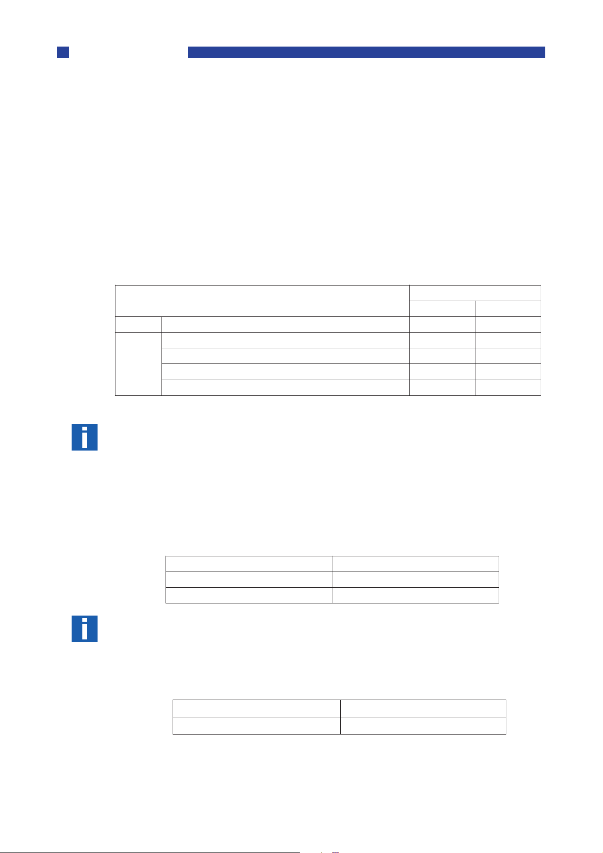
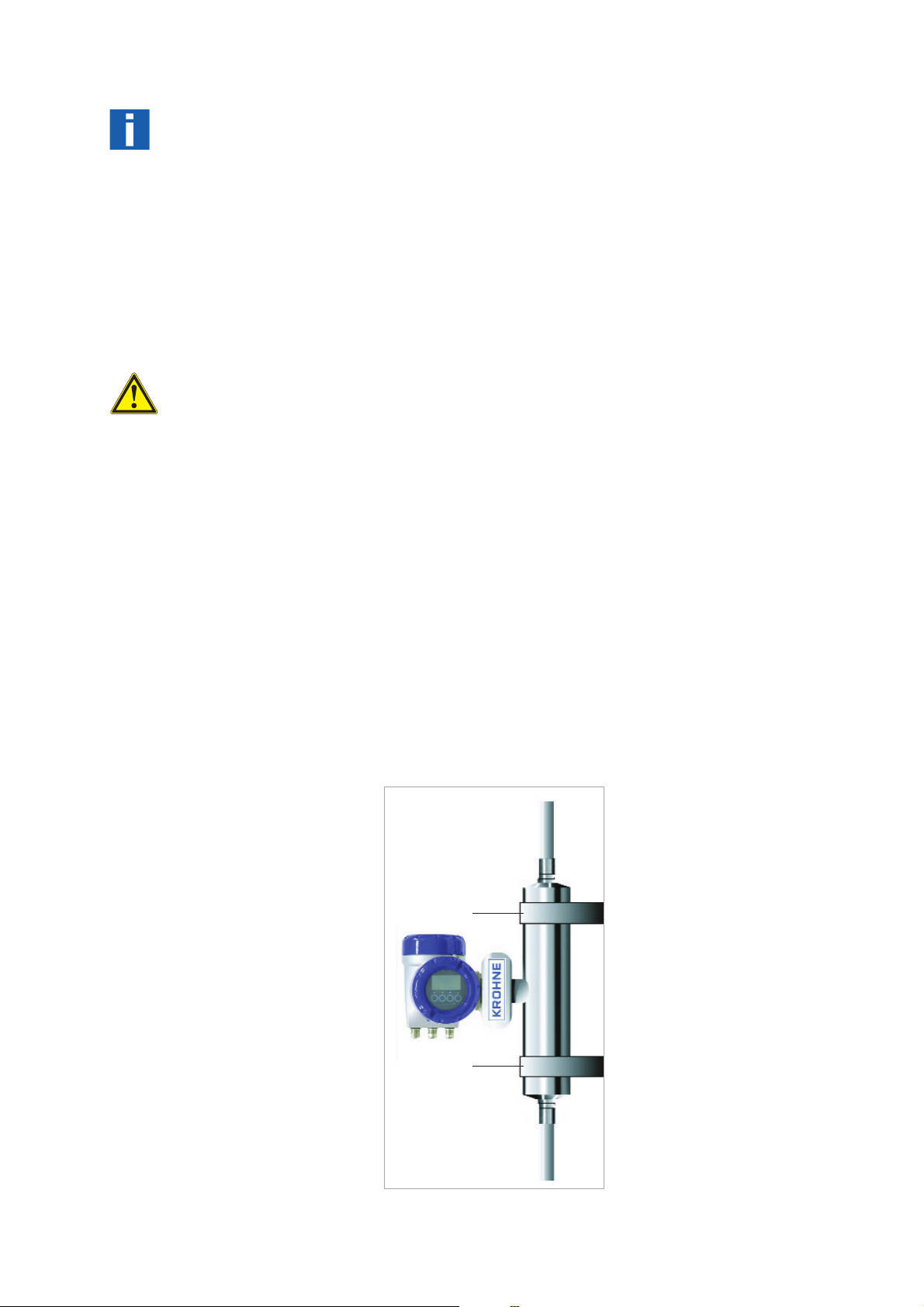
4.5 Hygienic Applications
The OPTIMASS 1000 series is available with a variety of hygienic process connectors.
When installing / using meters with hygienic process connectors, support /clamp the meter
properly. The meters are heavy and could injure when disconnected from the adjacent pipe
work.
The recommended method of installation is to mount the meter against a support / wall with
the body of the meter supported / clamped. The process pipe work can then be supported off
the meter. The meter is too heavy to be supported from the thin walled piping usually associated with the hygienic industry
1
1 2 Meter Supports
2
Page 14

14
The 3A approval for the 1000 series requires that it is “self draining”. Install the meter vertical-
Installation lengths
whichever is the lower.
Maximum pipe work forces
ly with the flow running uphill.
For installation lengths, please see section 4.9
Please check with KROHNE if you are unsure of the installation length. Many meters are built
to customer requirements / specifications especially where special hygienic process nectors
have been adapted to the meter. As these are normally non-standard, the installation length
will not be given in the technical data
It is also recommended that the seals be replaced regularly to maintain the hygienic integrity
of the connection.
Unless specifically requested, internal surfaces are not polished and no warranty is made as to
the surface finish.
If polishing option and /or EHEDG, ASME Bio-Processing or 3A approvals was selected at time
of order, all product contact surfaces are polished 0.5 micrometer Ra (20CLa) finish or better.
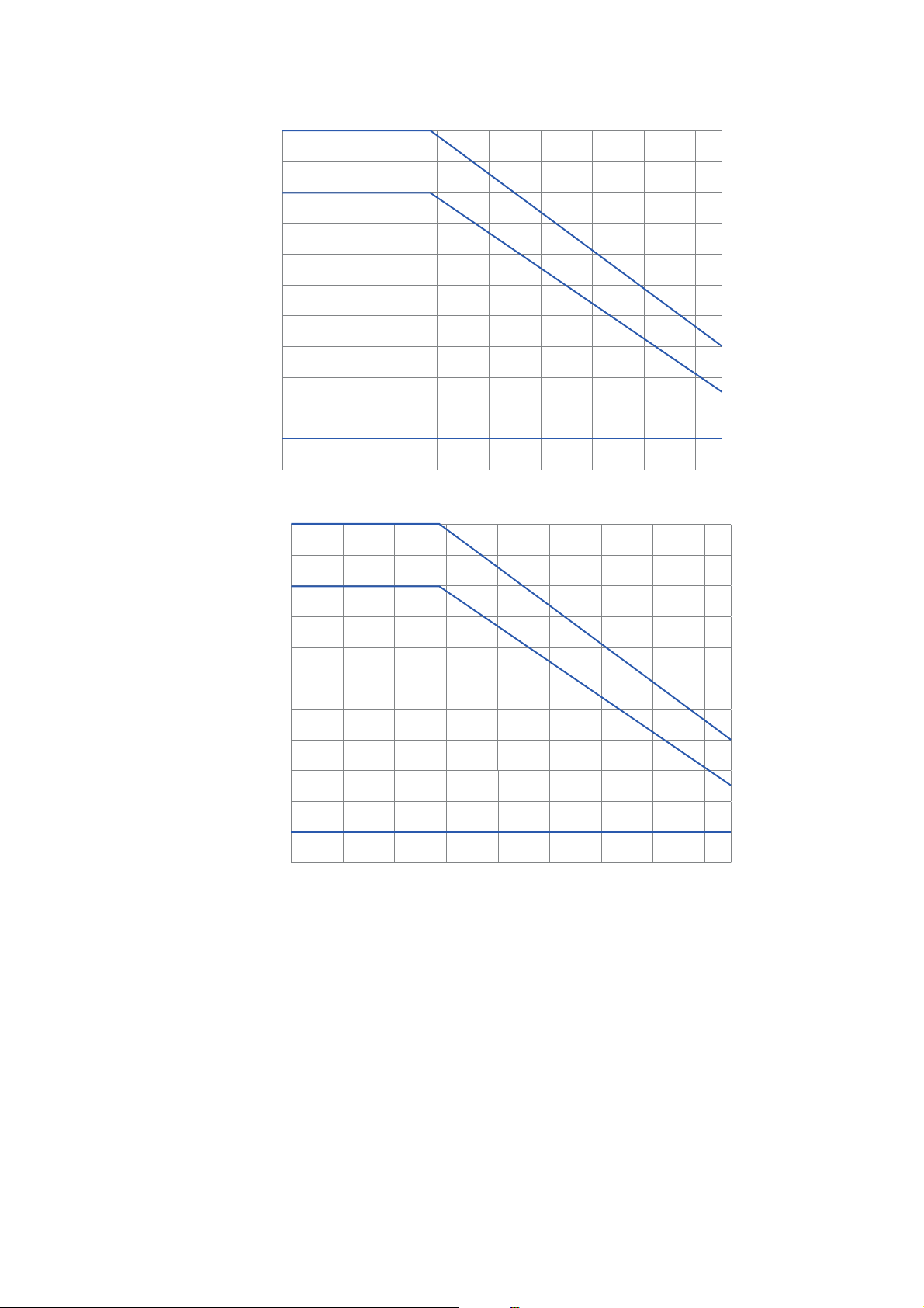
4.6 Pressure ratings
Tubes and secondary
pressure containment 100 barg
De-rated to 80 bar at 130°C (1160 psi at 266°F)
Heating Jacket 10 bar at 130°C (145 psi at 266°F)
Secondary pressure containment 63 barg 63 bar at 20°C (914 psi at 68°F)
De-rated to 50 bar at 130°C (725 psi at 266°F)
Meter data plates are stamped with maximum pressure rating at both 20°C (68°F) and max.
operating temperature of connection, primary tube or secondary pressure containment
20°C 130°C
40 bar 100 bar 32 bar 80 bar
Size Max Load Max Load Max Load Max Load
15 25 kN 17 kN 18 kN 12 kN
25 38 kN 19 kN 28 kN 12 kN
40 48 kN 15 kN 35 kN 7 kN
100 bar at 20°C (1450 psi at 68°F)
50 99 kN 20 kN 72 kN 8 kN
Flange Connections
These loads are roughly equivalent to the max axial loading allowed in an un-radiographed butt
weld in a 316L schedule 40 pipe.
Loads given are maximum static loads. If loads are cycling, particularly between tension and
compression, these loads should be reduced.
Please consult KROHNE for more information.
Page 15

15
Pressure de-rating (barg)
-40 -20 0 20 40 60 80 100 120 130
T
O
C
100
90
80
70
60
50
40
30
20
10
0
7
4
5
6
8
1
P (barg)
2
3
-40 -20 0 20 40 60 80 100 120 130
T
O
F
1450
1305
1160
1015
870
725
580
435
290
145
0
7
4
5
6
8
1
P (psig)
2
3
Pressure de-rating (psig)
1 Measuring tubes (PED & CRN 15/25) and outer cyclinder 316 (100 barg PED option) PN100,
DIN2637, PN100
2 CRN S40 measuring tube
3 CRN S30 measuring tube
4 Outer cylinder 304 & 316 (63 barg PED option), DIN 2636, PN 63
5 DIN 2635 PN 40
6 JIS 20K
7 JIS 10K
8 Hygienic connection
1 Measuring tubes (PED & CRN 15/25) and outer cyclinder 316 (1450 psig PED option)
2 CRN S40 measuring tube
3 CRN S30 measuring tube
4 ASME 600 lbs
5 Outer cyclinder 304 & 316 (914 psig PED option)
6 ASME 300 lbs
7 ASME 150 lbs
8 Hygienic connection
Page 16
16
Insulation
Electrical Heating
Size
DIM
DIN flange ratings based on EN 1092-1: 2001 table 18, 1% proof stress material group 14EO
ASME flange ratings based on ASME B16.5: 2003 table 2 material group 2.2
JIS flange rating based on JIS 2220: 2001 table 1 division 1 material group 022a
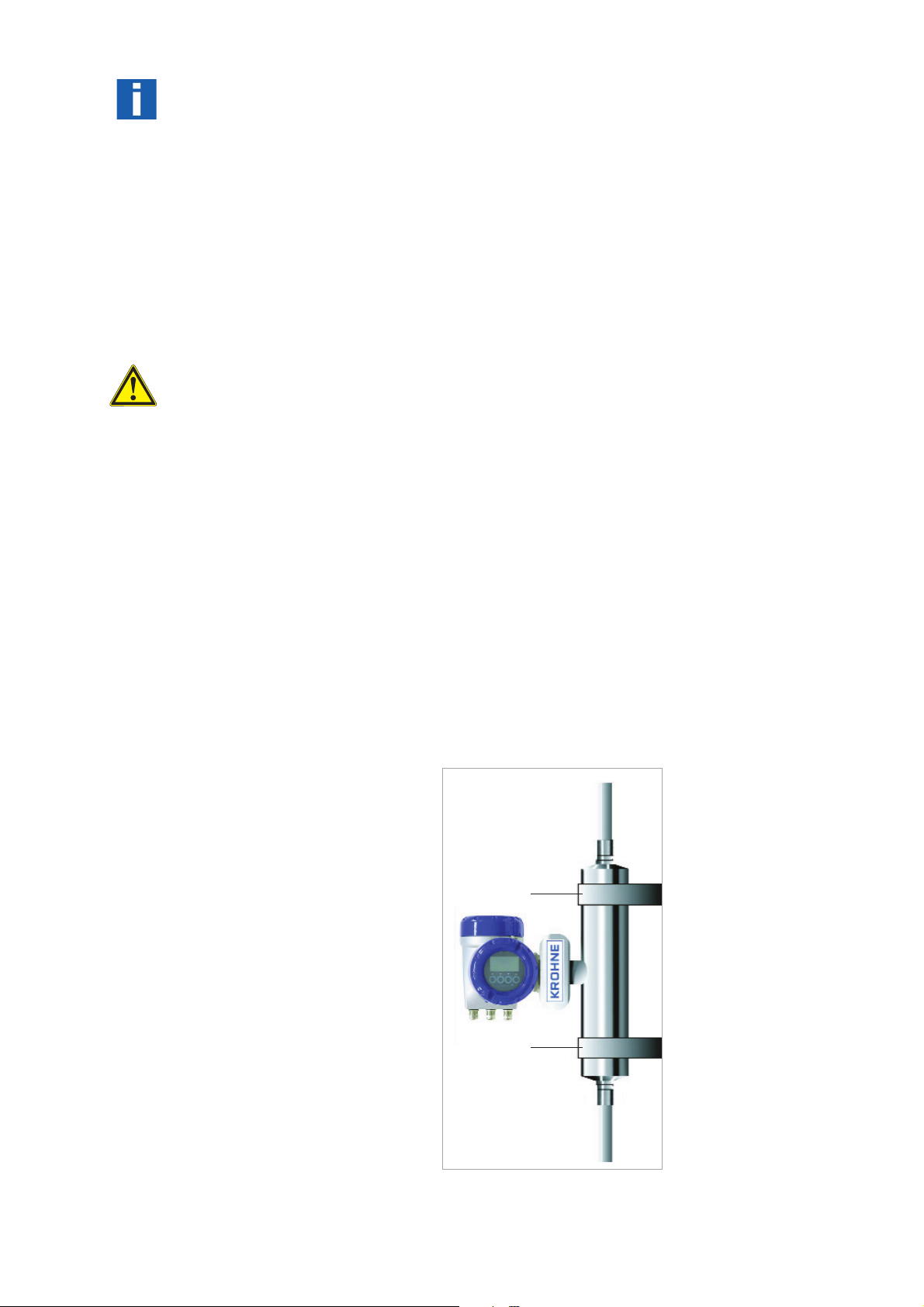
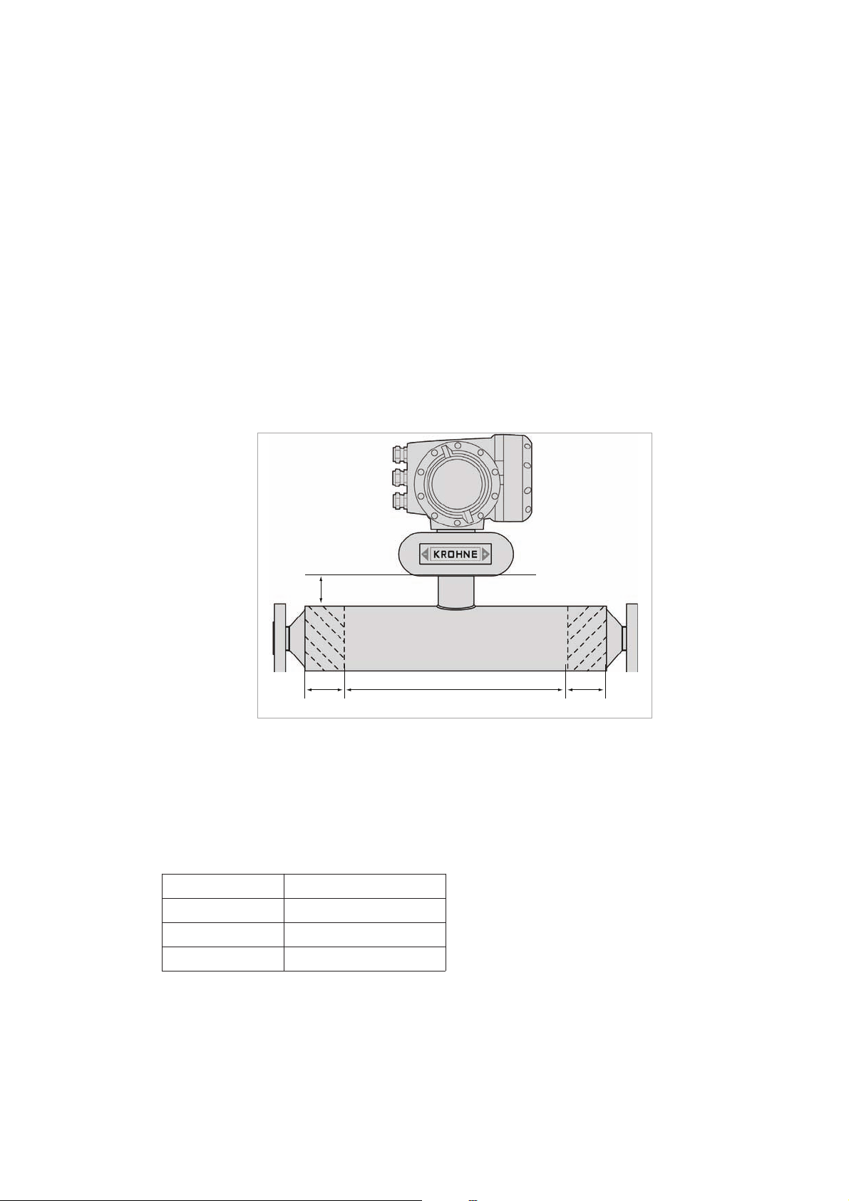
4.7 Heating and insulation
There are several ways to heat the meter. In most cases heating is unnecessary as the meter
is designed as such that very little heat is lost or gained through the outer cylinder.
Where insulation is required a variety of materials may be used to insulate the meter. Care
must be taken not to insulate the meter above the halfway mark of the electronics support post
as shown.
Electrical tape heating may be used. Care should be taken to only heat the sections where the
best effect will be achieved. Do not heat above the converter mount centre line See illustration.
1
2
3
2
1 Max insulation depth
2 Heated Areas
3 Do NOT heat this area
When insulating please observe guidelines as per insulation section.
2
15 65 mm
25 75 mm
40 110 mm
50 125 mm
Page 17
17
Cooling:
Important:
Heating Times (based on heating jacket operating at maximum temperature)
Liquid / S
team heating jacket
t
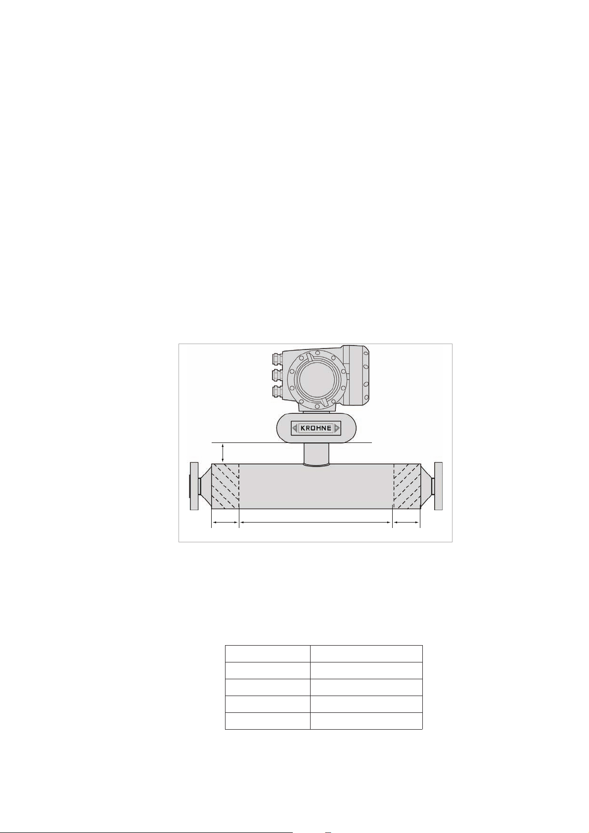
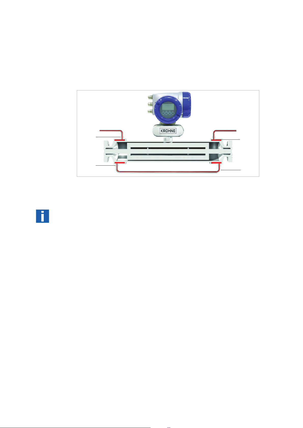
The meter can be supplied with a heating jacket. This jacket is designed to minimise the differential stress across the meter where differences in temperature between outer cylinder and
measuring tube exist.
The connections to the heating jacket are NPT or Ermeto sockets.
It is recommended that reinforced flexible hoses be used to connect the heating jacket to the
heat source.
1
3
2
4
1 2 3 4 Connection Points
Always heat the jacket to working temperature before flowing product in measuring tube.
Avoid the use of fluids that can cause crevice corrosion.
Although all the jacket materials are 316L, the outer cylinders are 304L (Optional 316L).
Connections should be made to ensure all air can be vented on liquid systems and all condensate can be drained on steam systems.
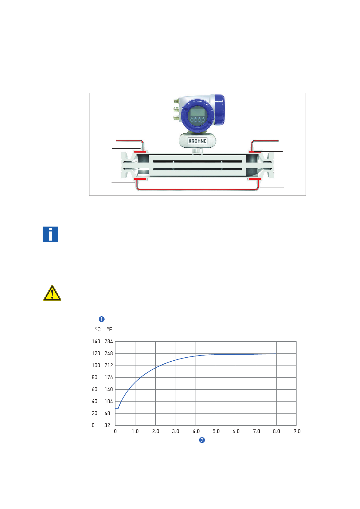
Note :
The maximum heating medium pressure and temperature for heating jackets is 10 bar at
130°C or 145 psig at 266°F.
1 Temperature at centre of measuring tube
2 Time (hours)
please consult KROHNE if cooling medium is to be used in the heating jacket.
Page 18
18
Minimum flow rate
4.8 Purge Port Meters and Burst Disc Meters
Weights (PN40 flanges)
15 25 40 50
kg lbs kg lbs kg lbs kg lbs
Kg/h
Lbs/min
Purge Port Options
If the purge port option was selected at time of order, then your meter will be fitted with ½”
NPT female connections – these will be clearly identified. These connections are sealed with
NPT plugs and PTFE tape.
Important:
Do not remove these plugs.
The meter is factory sealed with a dry nitrogen gas fill and any ingress of moisture will damage
the meter. The plugs should only be removed to purge the inside of the meter case of any
product if it is suspected that the primary measuring tube has failed. If it is suspected that the
primary tube has failed, depressurise and remove the meter from service, as soon as it is safe
to do so.
Burst Disc meters (Meters up to size 25 only)
OPTIMASS 1000 meters that have been ordered with a burst (rupture) disc will be suppled with
the disc fitted. The disc is fitted when the operating pressure of the measuring tube exceeds
the design pressure of the secondary containment. The disc failure pressure is 20bar @ 20°C.
Important:
The burst disc is suitable for the designed application according to the process conditions and
flow rates as per original order. If conditions alter, consult KROHNE for further advice regarding suitability of disc fitted.
If the product is in any way hazardous, it is strongly recommended that an exhaust tube is connected to the NPT male thread of the burst disc so that the discharge can be piped to a safe
area. This tube should be large enough that pressure cannot build up in the meter case.
Ensure arrow on burst disc is pointing away from meter
4.9 Technical Data
Maximum Flow Rates
15 25 40 50
Depending on measuring error required.
Compact with aluminium MFC 300 13.5 30 16.5 36 29.5 65 57.5 127
Compact with SS MFC 300 18.8 41 21.8 48 34.8 77 62.8 138
6,500 27,000 80,000 170,000
239 992 2,940 6,247
Remote with aluminium J box 11.5 25 14.5 32 25.5 56 51.5 113
Remote with SS J box 12.4 27 15.4 34 26.4 58 52.4 115
Page 19
19
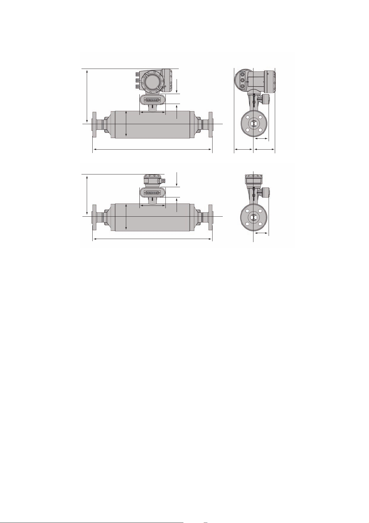
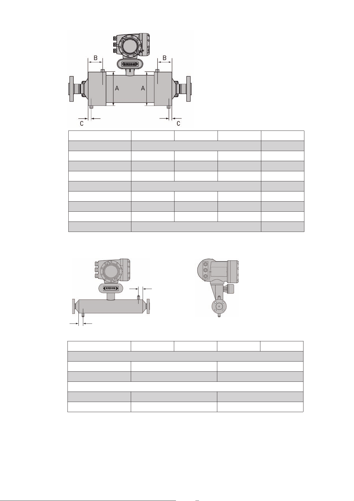
Dimensions
Flanged versions
1
B1
2
B2
F
E
A
G
D
H
I
1 Compact version
2 Remote Version
A
D
G
Page 20

20
Metric (mm)
DN15
DN 15 PN40
DN 25 PN40
DN 15 PN100
DN 25 PN100
½" ASME 150
½" ASME 300
½" ASME 600
¾" ASME 150
¾" ASME 300
¾" ASME 600
1” ASME 150
1” ASME 300
1” ASME 600
15A JIS 20K
A 101.6
B1 / B2 311 / 231
D 498 503 513 538 518 528 541 528 538 550 534 546 558 498 503
DN25
25A JIS 20K
DN 25 PN40
DN 40 P N40
DN 25 PN100
DN 40 PN100
1” ASME 150
1” ASME 300
1” ASME 600
1½” ASME 150
1½” ASME 300
1½” ASME 600
25A JIS 20K
40A JIS 20K
A 114.3
B1 / B2 317 / 237
D 531 541 567 575 563 575 589 575 589 603 531 541
DN40
DN 40 PN40
DN 40 PN100
DN 50 PN40
DN 50 PN63
DN 50 PN100
1½” ASME 150
1½” ASME 300
1½” ASME 600
2” ASME 150
2” ASME 300
2” ASME 600
40A JIS 20K
50A JIS 20K
A 168.3
B1 / B2 344 / 264
D 706 740 712 740 752 740 754 770 744 756 774 706 712
DN50
DN 50 PN40
DN 50 PN63
DN 50 PN100
DN 80 PN40
DN 80 PN63
DN 80 PN100
2” ASME 150
2” ASME 300
2” ASME 600
3” ASME 150
3” ASME 300
3” ASME 600
50A JIS 10K
A 219.1
50A JIS 10K
50A JIS 20K
80A JIS 10K
80A JIS 20K
B1 / B2 370 / 290
D 862 890 902 882 910 922 894 906 926 906 926 944 862 882
All sizes
E 160
F60
G 98.5
H 123.5
I 137
Page 21

21
Imperial (Inches)
DN15
DN 15 PN40
DN 25 PN40
DN 15 PN100
DN 25 PN100
½" ASME 150
½" ASME 300
½" ASME 600
¾" ASME 150
¾" ASME 300
¾" ASME 600
1” ASME 150
1” ASME 300
1” ASME 600
15A JIS 20K
A 4
B1 / B2 12.2 / 9.09
D 19 19.8 20.2 21.2 20.4 20.8 21.3 20.8 21.2 21.6 21 21.5 22 19.6 19.8
DN25
25A JIS 20K
DN 25 PN40
DN 40 P N40
DN 25 PN100
DN 40 PN100
1” ASME 150
1” ASME 300
1” ASME 600
1½” ASME 150
1½” ASME 300
1½” ASME 600
25A JIS 20K
40A JIS 20K
A 4.5
B1 / B2 12.5 / 9.3
D 20.9 21.3 22.3 22.6 22.2 22.6 23.8 22.6 23.2 23.7 20.9 22.8
DN40
DN 40 PN40
DN 40 PN100
DN 50 PN40
DN 50 PN63
DN 50 PN100
1½” ASME 150
1½” ASME 300
1½” ASME 600
2” ASME 150
2” ASME 300
2” ASME 600
40A JIS 20K
50A JIS 20K
A 6.6
B1 / B2 14.6 / 11.4
D 27.8 29.1 28 29.1 29.6 29.1 29.7 30.3 29.3 29.8 30.5 27.8 28
DN50
DN 50 PN40
DN 50 PN63
DN 50 PN100
DN 80 PN40
DN 80 PN63
DN 80 PN100
2” ASME 150
2” ASME 300
2” ASME 600
3” ASME 150
3” ASME 300
3” ASME 600
50A JIS 10K
A 8.6
50A JIS 10K
50A JIS 20K
80A JIS 10K
80A JIS 20K
B1 / B2 14.6 / 11.4
D 33.9 35 35.5 34.7 35.8 36.3 35.2 35.7 36.4 35.7 36.5 37.2 39.9 34.7
All sizes
E 6.3
F 2.4
G 3.9
H 4.9
I 5.4
Page 22
22
Hygienic versions
Metric (mm)
1
2
B2
D
D
E
E
A
A
F
F
G
G
H
I
B1
Meter 15 25
Conn DN25 1” DN40 1½”
DIN 11851
DIN 32676
DIN 11864-2
Tr-Clamp (ISO)
Tri-Clover
SMS
IDF
RJT
DIN 11851
DIN 32676
DIN 11864-2
Tr-Clamp (ISO)
Tri-Clover
SMS
IDF
RJT
A 101.6 114.3
B1 / B2 311 / 231 317 / 237
D 483 468 505 473 487 474 487 498 538 515 562 502 534 537 534 545
40 50
DN50 2” DN80 3”
DIN 11851
DIN 32676
DIN 11864-2
Tr-Clamp (ISO)
Tri-Clover
SMS
IDF
RJT
DIN 11851
DIN 32676
DIN 11864-2
Tr-Clamp (ISO)
Tri-Clover
SMS
IDF
A 168.3 219.1
B1 / B2 344 / 264 370 / 290
D 704 677 724 667 691 694 691 702 870 836 896 817 832 837 832 843
All sizes
E 160
F60
RJT
G 98.5
H 123.5
I 137
Page 23
23
Imperial (inches)
Meter 15 25
Conn DN25 1” DN40 1½”
DIN 11851
DIN 32676
DIN 11864-2
Tr-Clamp (ISO)
Tri-Clover
SMS
IDF
RJT
DIN 11851
DIN 32676
DIN 11864-2
Tr-Clamp (ISO)
Tri-Clover
SMS
IDF
A 4 4.5
B1 / B2 12.2 / 9.0 12.5 / 9.3
D 19 18.4 19.9 18.6 19.2 18.7 19.2 19.6 21.2 20.3 22.1 19.8 21 21.1 21 21.4
40 50
DN50 2” DN80 3”
DIN 11851
DIN 32676
DIN 11864-2
Tr-Clamp (ISO)
Tri-Clover
SMS
IDF
RJT
DIN 11851
DIN 32676
DIN 11864-2
Tr-Clamp (ISO)
Tri-Clover
SMS
IDF
A 6.6 8.6
B1 / B2 13.5 / 10.4 14.6 / 11.4
D 27.7 26.6 28.5 26.2 27.2 27.3 27.2 27.6 34.2 32.9 35.3 32.2 32.7 32.9 32.7 33.2
RJT
RJT
All sizes
E 6.3
F 2.4
G 3.9
H 4.9
I 5.4
Page 24
24
Purge Port
Heating Jacket
Meter size DN15 DN25 DN40 DN50
Connection size ½” (12mm) 1” (25mm)
Metric (mm)
A 115 ±1.0 142 ±1.0 206 ±1.0 254 ±1.0
B 515590105
C 20 26
Imperial (inches)
A 4.5 ±0.04 5.6 ±0.04 8.1 ±0.04 10.0 ±0.04
B 2.0 2.2 3.5 4.1
C 0.8 1.0
P
B
A
Meter size DN15 DN25 DN40 DN50
Metric (mm)
A 30 ±1.0 65 ±1.0
B 30 ±1.0 65 ±1.0
Imperial (inches)
A 1.2 ±0.04 2.5 ±0.04
B 1.2 ±0.04 2.5 ±0.04
Page 25
25
5
Measuring tube: Spigots
Meter Max. Temperature Shift
Process
Ambient
OPTIMASS 2000
5.1 Specific Installation Guidelines
• Tighten flange bolts evenly.
• Observe the pipe end loads as shown in S.5.6
• It is permissible to support the weight of the meter on the body.
• Use of standard pipework reducers at the flange is allowed. Avoid extreme changes in pipe
• The use of flexible hoses for connection to the process pipework is NOT recommended.
• The meter can be installed so that the converter is on the side of the meter, resulting in the
• The 2000 series has exceptional immunity to cross-talk, therefore allowing meters to be
5.2 Ambient / Process temperatures
The specified and approved ambient and process temperatures must be observed.
OPTIMASS
size (step changes).
measuring tubes on top of each other, unless gases or solids are being measured.
used in series or parallel
SS318L
°C °F
All meters -45...+130 -49...266
Compact Al. -40...+60 40...+140
Compact Al. with certain I/O options (consult Krohne) -40...+65 -40...+149
Compact SS -40...+55 -40...+131
Remote -40...+65 -40...+149
Note:
For additional temperature limits in hazardous area applications, reference should be made to
the publication “
Where meters are mounted in direct sunlight, it is recommended to install a sunshade that
covers the converter and front end. This is particularly important in countries with high ambient temperatures.
The maximum differential temperature between the process and ambient temperature without
insulation is 110°C or 200°F.
To avoid thermal shock, the meter MUST NOT be subject to rapid changes in process tempratures and reference should be made to the following table
Operation outside these limits may result in shifts in density and mass flow calibration.
Repeated shocking may also lead to premature failure of the meter! However, higher thermal
shocks are possible at lower working presures. Please consult Krohne for more information.
Guidelines for the use of Coriolis Meters in Hazardous Areas”.
S100 90°C (110°C with a max operating pressure of 40 barg)
S150 80°C
S250 50°C
5.3 Pressure Equipment Directive (PED) requirements
To comply with the requirements of the PED in Europe, the following information is provided to
assist the plant engineer in installing the meter:
Stainless Steel UNS 531803 Stainless Steel UNS J902205
The outer cylinder 304 / 304L is dual certified (Optional outer cylinder of 316 / 316L).
Wiring feedthrough is made of Epoxy (or PEEK) with 2 ‘O’ ring seals in Fpm / fkm &
Hydrogenated Nitrile.
Page 26
26
Flanges:
PN160/250 and ASME 900/1500 are duplex stainless steel (UNS 531803). All other flanges are
316 / 316 L dual certified (optional UNS 531803).
NOTE: if the NACE option has been selected at the time of order, the flanges will be duplex
stainless steel (UNS 31803).
Hygienic Connections are 316L (S100 only)
Optional heating jacket 316 / 316L
Note: Outer cylinder is in contact with heating medium
5.4 Secondary Pressure containment
The OPTIMASS 2000 meters are supplied (as standard) without certified housings that have a
typical burst pressure
If the user suspects that the primary tube has failed, the unit must be depressurised and
removed from service as soon as it is safe to do so.
Note:
In the 2000 Series there is a high pressure wire feed through with ‘O’ rings that might not be
compatible with the process fluid for an extended period if a primary tube fails.
It is the user’s responsibility to ensure that the materials used are compatible with this product.
>100 barg.
Other ‘O’ ring materials are available on request.
5.5 Hygienic Applications
The OPTIMASS 2000 (S100) is available with a variety of hygienic process connectors.
When installing / using meters with hygienic process connectors, support /clamp the meter
properly. The meters are heavy and could injure when disconnected from the adjacent pipe
work.
The recommended method of installation is to mount the meter against a support / wall with
the body of the meter supported / clamped. The process pipe work can then be supported off
the meter. The meter is too heavy to be supported from the thin walled piping usually associated with the hygienic industry. For information regarding lifting the meter, please refer to section 3.4.
1
2
1 2 Meter Supports
Page 27

27
whichever is the lower
Maximum pipe work forces
The 3A approval for the 2000 series requires that it is “self draining”. Therefore, the meter
MUST be installed vertically with the flow running uphill.
Installation lengths
For installation lengths, please see section 5.9
Please check with KROHNE if you are unsure of the installation length. Many meters are built
to customer requirements / specifications especially where special hygienic process nectors
have been adapted to the meter. As these are normally non-standard, the installation length
will not be given in the technical data.
5.6 Pressure Ratings
Measuring Tube PED certification
See pressure de-rating graphsMeasuring Tube FM certification
Measuring Tube CRN & CSA certification
Meter data plates are stamped with maximum pressure rating at both 20°C (68°F) and maximum operating temperature of connection or primary tube,
size 20°C 130°C
.
40 barg 100 barg 150 barg 32 bar 80 barg 115 barg
100 150 kN 100 kN 150 kN 60 kN
150 650 kN 120 kN 280 kN 50 kN
250 550 kN 60 kN 400 kN 50 kN
Flange Connections
These loads are roughly equivalent to the max axial loading allowed in an un-radiographed butt
weld in a 316L schedule 80 pipe.
Loads given maximum static loads. If loads are cycling, particularly between tension and compression then these loads should be reduced.
Please consult KROHNE for more information.
Page 28
28
Flanges
Note:
WHICHEVER IS THE LOWER!
-40 -20 0 20 40 60 80 100 120 130
P (bar)150
145
140
135
130
125
120
115
110
105
100
0
2
3
1
P
Pressure de-rating
P (psi) 2176
2103
2030
1958
1885
1813
1740
1668
1595
1523
1450
0
-40 -4 32 68 104 140 176 212 248 266
O
F
T
1 Measuring Tube PED certification
2 Measuring Tube FM certification
3 Measuring Tube CRN & CSA certification
DIN flange ratings based on EN 1092-1 2007 table G.4.1 material group 14E0
1
2
3
ASME flange ratings based on ASME B16.5 2003 table 2 material group 2.2
JIS flange ratings based on JIS 2220: 2001 table 1 division 1 material group 022a
The maximum operating pressure will be either the flange rating or measuring tube rating
It is recommended that the seals be replaced regularly to maintain the hygienic integrity of the
connection.
Page 29
29
Unless specifically requested, internal surfaces are not polished and no warranty is made as to
Insulation
Electrical Heating
Size
DIM
the surface finish.
If polishing option and /or EHEDG, ASME Bio-Processing or 3A approvals was selected at time
of order, all product contact surfaces are polished 0.5 micrometer Ra (20CLa) finish or better.
5.7 Heating and insulation
There are several ways to heat the meter. In most cases heating is unnecessary as the meter
is designed so that very little heat is lost or gained through the outer cylinder.
Where insulation is required, a variety of materials may be used to insulate the meter. Care
must be taken not to insulate the meter above the halfway mark of the electronics support post
as shown.
Electrical tape heating may be used. Care should be taken to only heat the sections where the
best effect will be achieved. Do not heat above the converter mount centre line as shown
above.
The following guidelines must be observed.
1
2
1 Max insulation depth
2 Heated Areas
3 Do NOT heat this area
When insulating please observe guidelines as per insulation section.
100 200 mm
150 250 mm
250 250 mm
1
3
2
Page 30
30
Liquid / Steam heating jacket
Important:
Heating Times
The meter can be supplied with a heating jacket. This jacket is designed to minimise the differential stress across the meter where differences in temperature between outer cylinder and
measuring tube exist.
The connections to the heating jacket are NPT or Ermeto sockets.
It is recommended that reinforced flexible hoses be used to connect the heating jacket to the
heat source.
1
3
2
4
1 2 3 4 Connection Points
Always heat the jacket to working temperature before flowing product in measuring tube.
Avoid the use of fluids that can cause crevice corrosion.
Although all the jacket materials are 316L, the outer cylinders are 304L (Optional 316L).
Connections should be made to ensure all air can be vented on liquid systems and all condensate can be drained on steam systems.
Note :
Max heating medium pressure and temperature for heating jackets is 10 bar at 130°C or 145
psig at 266°F.
The heating times shown in the following illustrations are based on the heating jacket operating at maximum temperature and show the measured temperatures at the spigot end of the
measuring tubes. If a desired temperature is required in the centre of the measuring tubes,
then the heating times MUST be extended.
Page 31

31
O
OPTIMASS 2000 S100
OPTIMASS 2000 S150
OPTIMASS 2000 S250
1
OCO
F
140 284
120 248
100 212
80 176
60 140
40 104
20 68
032
0 0.5 1 1.5 2 2.5
1
OCO
F
140 284
120 248
100 212
80 176
60 140
40 104
20 68
032
0 0.5 1 1.5 2 2.5 3 3.5 4
1
OCO
F
2
2
140 284
120 248
100 212
80 176
60 140
40 104
20 68
032
0 0.5 1 1.5 2 2.5 3 3.5 4 4.5 5
2
1 Temperature at spigot end of measuring tubes
2 Time (hours)
Page 32

32
Purge Port Options
Burst Disc meters
Maximum Flow Rates
Kg/h
Lbs/min
Minimum Flow Rates
Kg/h
Lbs/min
Weights (PN40 Flanges)
100 150 250
kg lbs kg lbs kg lbs
Cooling
Please consult KROHNE if cooling medium is to be used in the heating jacket.
5.8 Purge Port Meters and Burst Disc Meters
If the purge port option was selected at time of order, then your meter will be fitted with ½”
NPT female connections – these will be clearly identified. These connections are sealed with
NPT plugs and PTFE tape.
Important:
Do not remove these plugs.
The meter is factory sealed with a dry nitrogen gas fill and any ingress of moisture will damage
the meter. The plugs should only be removed to purge the inside of the meter case of any
product if it is suspected that the primary measuring tube has failed. If it is suspected that the
primary tube has failed, depressurise and remove the meter from service, as soon as it is safe
to do so.
OPTIMASS 2000 meters that have been ordered with a burst (rupture) disc will be suppled with
the disc fitted. The disc failure pressure is 20barg @ 20°C.
Meters fitted with connection ratings in excess of 100 barg,(1450 psig) will be supplied with a
burst disc fitted.
Important:
The burst disc is suitable for the designed application according to the process conditions and
flow rates as per original order. If conditions alter, consult KROHNE for further advice regarding suitability of disc fitted.
If the product is in any way hazardous, it is strongly recommended that an exhaust tube is connected to the NPT male thread of the burst disc so that the discharge can be piped to a safe
area. This tube should be large enough that pressure cannot build up in the meter case.
Ensure arrow on burst disc is pointing away from meter
5.9 Technical Data
100 150 250
420,000 900,000 2,300,000
14,698 33,804 84,510
Dependant on measuring error required
Dependant on measuring error required
Compact with aluminium MFC 300 84.8 187 211.5 466 444.5 980
Compact with SS MFC 300 90.1 198 216.8 478 449.8 991
Remote with aluminium J box 80.8 178 207.8 457 440.5 971
Remote with SS J box 81.7 180 208.4 459 441.4 973
Page 33

33
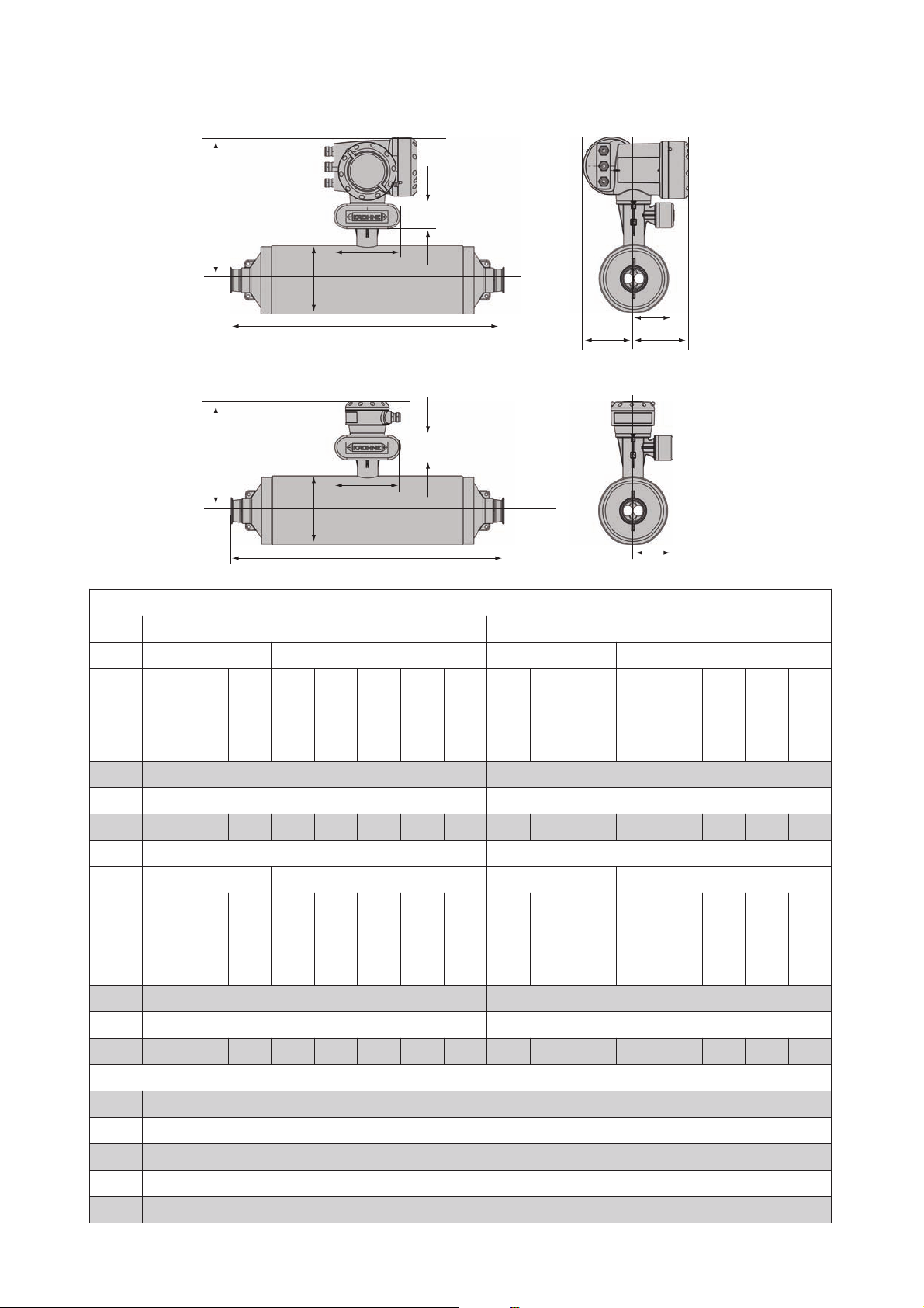
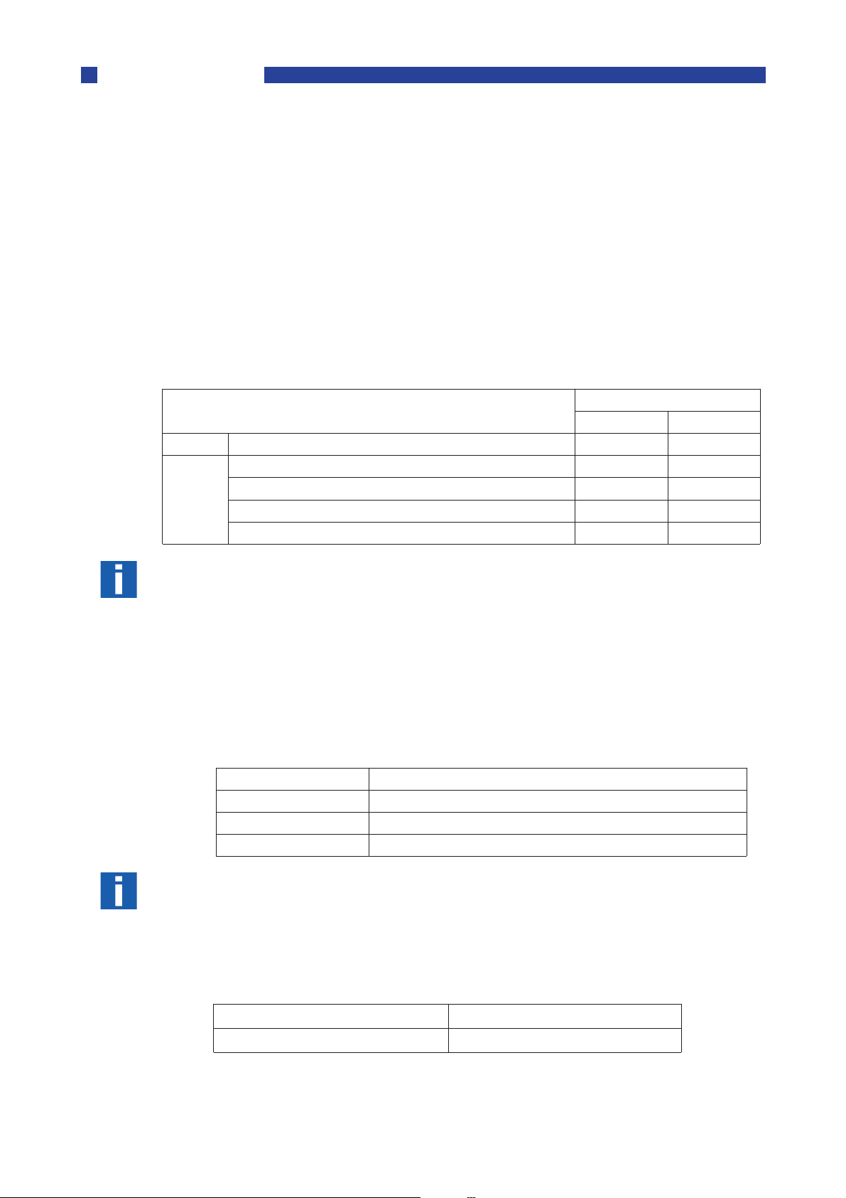
Dimensions (Flanged versions)
1
C1
2
D
E
A
B
D
E
FHG
C2
1 Compact version
2 Remote Version
A
B
H
Page 34

34
Metric (mm)
DN100
DN 100 PN40
DN 150 PN40
DN 100 PN63
DN 150 PN63
DN 100 PN100
DN 150 PN100
4” ASME 150
4” ASME 300
4” ASME 600
4” ASME 900
6” ASME 150
6” ASME 300
6” ASME 600
6” ASME 900
JIS 10K
A 219
B 1310 1330 1336 1370 1360 1410 1334 1352 1398 1422 1358 1378 1428 1474 1332
C1 / C2 370 ±5 / 293±5
DN150
DN 150 PN40
DN 200 PN40
DN 150 PN63
DN 200 PN63
DN 150 PN100
DN 200 PN100
6” ASME 150
6” ASME 300
6” ASME 600
6” ASME 900
8” ASME 150
8” ASME 300
8” ASME 600
8” ASME 900
JIS 10K
A 323
B 1621 1647 1661 1691 1701 1731 1649 1669 1719 1765 1675 1695 1751 1809 N/A
C1 / C2 422 ±5 / 345 ±5
DN250
JIS 20K
JIS 20K
DN 250 PN40
DN 300 PN40
DN 250 PN63
DN 300 PN63
DN 250 PN100
DN 300 PN100
10” ASME 150
10” ASME 300
10” ASME 600
10” ASME 900
12” ASME 150
12” ASME 300
12” ASME 600
12” ASME 900
JIS 10K
JIS 20K
A 406
B 2030 2050 2070 2100 1977 2160 2024 2056 2138 2202 2050 2082 2146 2234 N/A
C1 / C2 463 ±5 / 386 ±5
All sizes
D 160
E60
F 123.5
G 137
H 98.5
Page 35

35
Imperial (inches)
Hygienic connections (S100 only)
DN100
DN 100 PN40
DN 150 PN40
DN 100 PN63
DN 150 PN63
DN 100 PN100
DN 150 PN100
4” ASME 150
4” ASME 300
4” ASME 600
4” ASME 900
6” ASME 150
6” ASME 300
6” ASME 600
6” ASME 900
JIS 10K
A 8.6
B 51.6 52.4 52.6 53.9 53.5 55.5 52.5 53.2 55 56 53.5 54.2 56.2 58 52.4
C1 / C2 14.6 ±0.2 / 11.5 ±0.2
DN150
DN 150 PN40
DN 200 PN40
DN 150 PN63
DN 200 PN63
DN 150 PN100
DN 200 PN100
6” ASME 150
6” ASME 300
6” ASME 600
6” ASME 900
8” ASME 150
8” ASME 300
8” ASME 600
8” ASME 900
JIS 10K
A 12.7
B 63.8 64.8 65.4 66.6 67 68.1 65 65.7 67.7 69.5 65.5 66.7 69 71.2 N/A
C1 / C2 16.6 ±0.2 / 13.6 ±0.2
DN250
JIS 20K
JIS 20K
DN 250 PN40
DN 300 PN40
DN 250 PN63
DN 300 PN63
DN 250 PN100
DN 300 PN100
10” ASME 150
10” ASME 300
10” ASME 600
10” ASME 900
12” ASME 150
12” ASME 300
12” ASME 600
12” ASME 900
JIS 10K
A 16
B 80 80.7 81.5 82.7 77.8 85 79.7 81 84.2 86.7 80.7 82 84.5 88 N/A
C1 / C2 18.2 ±0.2 / 15.2 ±0.2
All sizes
D 6.3
E 2.4
F 4.9
G 5.4
H 3.9
DN100 4”
DIN 11864-2
DIN 11851
DIN 32676
Tri-Clover
Tri-clamp
(ISO)
SMS
IDF
RJT
Metric (mm)
B 1296 1288 1236 1223 1223 1236 1223 1234
Imperial (inches)
B 51 50.1 48.7 48 48 48.7 48 48.6
JIS 20K
Page 36

36
Purge Port
Heating Jacket
S100 S150 S250
S100 S150 S250
BB
A
CC
All flanges All flanges All flanges
mm
A 254 ±2.5 355 ±2.5 444 ±2.5
B 178 ±2.0 228 ±2.0 208 ±2.0
C 28 ±2.0 28 ±2.0 6.5 ±2.0
inches
A 10 ±0.1 14 ±0.1 17.5 ±0.06
B 7 ±0.08 9 ±0.08 8.2 ±0.08
C 1.1 ±0.08 1.1 ±0.08 0.25 ±0.08
A
All flanges All flanges All flanges
mm
A 70 ±1.0 100 ±1.0
B 70 ±1.0 100 ±1.0
inches
A 2.75 ±0.04 4.0 ±0.04
B 2.75 0.04± 4.0 ±0.04
B
Page 37

37
6
Orientation:
Meter Size Angle of Rotation (Clockwise)
OPTIMASS 3000
6.1 Specific Installation Guidelines
The OPTIMASS 3000 is a single Z Shaped Tube Meter. During installation, the following general
guidelines MUST be followed:
• The base plate has four holes to enable the meter to be mounted and all four mounting
• The plastic inserts in the base plate mounting holes are important to ensure a rigid and sta-
• It is important to mount on a firm and rigid structure to obtain a stable zero condition.
• The following guidelines are provided to assist the installer to select the best option:
The meter can be mounted horizontally or vertically
If mounting vertically the meter MUST be mounted with the flow uphill and with a set angle
from the vertical that allows the meter to self drain The set angles are:
OPTIMASS
holes MUST be used
ble connection to the mounting structure.
01 7°
03 13°
04 13°
1 2 3
1 Horizontal Mount
2 7° clockwise rotation from the vertical. (See angle markings on base plate).
3 13° clockwise rotation from the vertical. (See angle markings on base plate).
DO NOT allow the pipework to carry the weight of the meter This
will cause severe damage!
DO NOT mount the meter upside down!
Page 38

38
Flanged and Tri-clamp Meters
Measuring tube:
SS316L or HC22
Process
Ambient
When installing these meters ensure that the pipework is supported behind the process , so
that no unnecessary stress is applied to the meter flanges.
443
1 Fix meter to a firm support
2 Carefully align the process flanges and connect
3 Support the process pipe close to the flanges. Do not pull pipe with clamps!
4 Make the final process connections. If there are no connections in this area, try to have
some flexibility in the process pipe
Note:
Please note that gas bubbles can also accumulate between flange and measuring tube due to
the step change, mount vertically to avoid this.
2
1
2
3
6.2 Ambient / Process temperatures
The specified and approved ambient and process temperatures must be observed.
°C °F
Note:
For additional temperature limits in hazardous area applications, reference should be made to
the publication “
Where meters are mounted in direct sunlight, it is recommended to install a sunshade. This is
particularly important in countries with high ambient temperatures.
Compact Aluminium -40 ... +60 -40 ... +140
Compact Stainless -40 ... +55 -40 ... +130
Remote -40 ... +60 -40 ... +140
Guidelines for the use of Coriolis Meters in Hazardous Areas”.
-40 ... +150 -40 ... +300
6.3 Pressure Equipment Directive (PED) requirements.
To comply with the requirements of the PED in Europe, the following information is provided to
assist the plant engineer in installing the meter.
The outer casing (Secondary Pressure containment) is 316L
S Stainless SS 316 L
H Hastelloy C22
Wiring feedthrough is made of epoxy with ‘0’ ring seals in FPM / FKM and hydrogenated nitrile.
Connections are all 316 / 316 L dual certified or Hastelloy C22
The optional heating jacket is 316 or 316L.
Page 39

39
Note :
Pressure De-rating:
Stainless Steel tubes:
Hastelloy C22 tubes:
The outer casing is in contact with the heating medium.
6.4 Secondary Pressure containment
The OPTIMASS 3000 meters are supplied with secondary pressure containment as standard.
20 °C 50°C 100°C 150°C
30 bar 28.5 bar 26.1 bar 24 bar
The maximum secondary containment pressure (as certified) is 30 barg at 20°C (435 psig at
70°F), de-rated as follows :
The de-rating is based on the reduction of material strength with temperature for 316L (W No.
1.4404) material from DIN 17456.
Heating jacket is rated to 10 barg at 150°C (145 psig at 300°F).
If a heating jacket fitted, secondary containment is limited to 10 barg at 150°C (145 psig at
300°F). This is because the jacket is fitted inside of the secondary containment dome.
If the meter operating pressure is higher than the secondary containment allowable pressure
then a relief or bursting disc option (fitted in the dome) MUST be ordered. In this case the
meter data plate is stamped with maximum pressure rating (at 20°C and maximum operating
temperature) of the connection or the primary tube (whichever is the lower).
If the user suspects that the primary tube has failed, the unit must be depressurised and
removed from service as soon as it is safe to do so.
Notes:
• In the 3000 series there is a high pressure wire feed through with ‘O’ rings that might not be
compatible with the process fluid for an extended period if a primary tube fails.
• It is the user’s responsibility to ensure that the materials used are compatible with this
product.
• Other ‘O’ ring materials are available on request.
• Burst disc options ARE NOT available in combination with a heating jacket.
6.5 Pressure Ratings
Meter data plates are stamped with maximum pressure rating (at 20°C and max. operating
temperature) of connection, primary tube or secondary pressure containment (whichever is the
lower).
150 bar at 80°C or 2175 psi at 175°F
50 bar at 150°C or 725 psi at 300°F
150 bar at 150°C or 2175 psi at 300°F
(no de-rating required)
Page 40

40
Flanged connections as per DIN 2501 (metric)
Notes:
Flanged connections as per DIN 2501 (Imperial)
1 ASME 6000 lbs with HC22 measuring tube
2 ASME 600 lbs with 316L measuring tube
3 DIN 2636 PN63
4 ASME 300 lbs
5 JIS 20K
6 DIN 2635 PN40
7 ASME 150 lbs
8 Hygienic connection
•All hygienic type process connections rated to 10 barg @20°C (145psig @68°F)
•If operating pressure is above 30 barg (435 psig) the burst disc option MUST be purchased.
•Ensure that the meters are used within their operating limits.
Page 41

41
NPT connections (metric)
NPT connections (Imperial)
Notes:
1 Hastelloy C22 measuring tube with ¼” NPT connections
2 SS 316L measuring tube with ¼” NPT connections
3 30 barg secondary containment
1 Hastelloy C22 measuring tube with ¼” NPT connections
2 SS 316L measuring tube with ¼” NPT connections
3 435 psig secondary containment
•If operating pressure is above 30 barg (435 psig) the burst disc option MUST be purchased.
•Ensure that the meters are used within their operating limits.
6.6 Heating and insulation
All secondary containment and heated jacket parts are 316L, except the ¼" NPT Female connections, which are 316.
Max heating medium pressure and temperature is 10 bar at 150°C or 145 psig at 300°F.
The max secondary containment pressure on the OPTIMASS 3000 when fitted with a heating
jacket is 10 bar at 150°C or 145 psig at 300°F.
Page 42

42
Important:
Burst Disc meters:
Make sure that the arrow on the burst disc is pointing aw
ay from the meter.
Heating Jacket & Purge Port dimensions
01 03 04
A
BC
All flanges All flanges All flanges
mm
A 129 ±5.0
B 45° ±6.0
C 45° ±6.0
D
D 45° (approx)
inches
A 5.01 ±0.2
6.7 Purge Port Meters and Burst Disc Meters
Purge Port Options
If the purge port option was selected at the time of order, then your meter will be fitted with ¼"
NPT female connections and will be clearly identified. These connections are sealed with NPT
plugs and PTFE tape.
Do not remove these plugs.
The meter is factory sealed with a dry nitrogen gas fill and any ingress of moisture will damage
the meter. The plugs should only be removed to purge the inside of the meter case of any
product if it is suspected that the primary measuring tube has failed. If it is suspected that the
primary tube has failed, depressurise and remove the meter from service, as soon as it is safe
to do so.
OPTIMASS 3000 meters that have been ordered with a burst (rupture) disc will have the disc
fitted during manufacture. The burst disc option MUST be ordered for applictions where the
operating pressure of the measuring tube, exceeds the design pressure of the secondary containment. The disc failure pressure is 20bar @ 20°C.
Important:
The burst disc is suitable for the designed application according to the process conditions and
flow rates as per original order. If conditions alter, consult KROHNE for further advice regarding suitability of the fitted disc.
If the product is in any way hazardous, it is strongly recommended that an exhaust tube is connected to the NPT male thread of the burst disc so that the discharge can be piped to a safe
area. This tube should be large enough that pressure cannot build up in the meter case.
a
Page 43

43
Weights
6.8 Technical Data
Maximum flow rate
Secondary pressure containment
Size
Kg
lbs
Kg/h
Lbs/min
Nominal Flow Rates
01 03 04
Typically 130 % of the nominal flow rate for the sensor size depending on application.
Minimum flow rate
Depending on measuring error required.
Tube materials:
15 100 350
0.5 3.5 12.5
• S 316L
• Hastelloy C22
The meter size has a prefix S or H indicating the tube material.
• All OPTIMASS 3000 Series meters have secondary containment rated to 30 bar or 435 psi.
Materials of construction
• Connections: SS 316 L or HC22
• Secondary Containment: SS 316 L
• Front end housing and post: SS 316 L
• Converter housing/remote junction box: Epoxy coated aluminium or stainless steel
Weight of OPTIMASS 3000 sensor fitted with a typical standard connection in kg (lbs)
01 03 04
12 12 12
26.4 26.4 26.4
Page 44

44
Dimensions
1
D1
2
D2
E
C
B
3
A
G
H
F
K
C
B
A
G
1 Compact version
2 Remote Version
All dimensions (mm)
S/H 01 S/H 03 S/H 04
A
1 1 1
B 160
C 60
D1 348
D2 269
E 123.5
F 137
G 98.5
I
H 156
I 180
K 132
Measuring tube inner diameter 1.2 2.6 4.0
1 depending on process connection. See table for dimensions
Page 45

45
All dimensions (inches)
S/H 01 S/H 03 S/H 04
A
1 1 1
B6.3
C 2.4
D1 13.7
D2 10.6
E4.9
F 5.4
G3.9
H 6.1
I7.1
K 5.2
Measuring tube inner diameter 0.05 0.1 0.2
1 depending on process connection. See table for dimensions
Dimension of A in mm & inches for all available process connector lengths
A
Connection type mm inches
¼” NPT 256 ±3 10.1 ±0.1
ASME 150 286 ±3 11.3 ±0.1
ASME 300 286 ±3 11.3 ±0.1
ASME 600 295 ±3 11.6 ±0.1
DIN15 PN40 286 ±3 11.3 ±0.1
DIN15 PN63 295 ±3 11.6 ±0.1
15A JIS20K 286 ±3 11.3 ±0.1
DIN10 DIN32676 260 ±3 10.2 ±0.1
½” Tri-Clover clamp 262 ±3 10.3 ±0.1
www.krohne.com
Page 46

46
7
Note:
Measuring tube: Sealing Faces:
Note:
OPTIMASS 7000
7.1 Specific Installation Guidelines
• Tighten flange bolts evenly.
• Observe min and max pipe end loads at the end of this section.
The use of reducers at the flanges is allowed but extreme pipe size reductions should be avoided. This is to prevent the possibility of cavitation and degassing.
There are no additional installation requirements for the OPTIMASS 7000 sensors. Fixing of
flexible hoses directly on the meter is allowed.
7.2 Ambient/Process Temperatures
The specified and approved ambient and process temperatures MUST be observed.
Titanium
°C -40...+150 -20...+150 -40...+60
°F -40...+300 4...+300 -40...+140 -40...+130 -40...+140
Process Ambient
Hygienic/aseptic
connections
1
Compact Al Compact S.S Remote
-40...+55 -40...+60
3
OPTIMASS
HC22 /
Tantalum
SS318L
°C 0...+100 -40...+60
°F 0...212 -40...+140 -40...+130 -40...+140
°C 0...+100 0...+130
°F 0...212 0...266 -40...+140 -40...+130 -40...+140
1 Available across the whole range (½”ASME on the T15)
2 Option available on 25, 40, 50 & 80 meters
3 Temp range: -40...+65°C (-40...+149°F) on certain I/O options. Pleae call Krohne for details
For additional temperature limits in hazardous area applications, reference should be made to
the publication “
Where meters are mounted in direct sunlight, it is recommended that a sunshade is installed.
This is particularly important in countries with high ambient temperatures!
The maximum differential temperature between the process and ambient temperature without
insulation is 130°C or 266°F for Titanium and 80°C or 1 76°F for Hastelloy, Stainless Steel and
Tantalum meters.
Guidelines for the use of Coriolis Meters in Hazardous Areas”.
-40...+60
2
3
3
-40...+55 -40...+60
-40...+55 -40...+60
7.3 Pressure Equipment Directive (PED) Requirements.
To comply with the requirements of the PED in Europe, the following information is provided to
assist the plant engineer in installing the meter.
Titanium Grade 9 Titanium Grade 2
Hastelloy C22 Hastelloy C22
Stainless UNS 31803 Stainless UNS 31803
Tantalum grade RO5255 Tantalum grade RO5255
The outer cylinder 304 / 304L is dual certified (Optional outer cylinder of 316 / 316L). This also
applies to PED certified housings.
Wiring feedthrough is made of Epoxy.(or PEEK) with 2 ’O’ ring seals of FPM / FKM &
Hydrogenated Nitrile
Flanges all 316 / 316 L dual certified.
Optional heating jacket 316 / 316L.
The outer cylinder is in contact with heating medium
Page 47

47
7.4 Secondary Pressure Containment
Note:
Installation lengths:
The OPTIMASS 7000 meters are supplied (as standard) without certified housings that have a
typical burst pressure
Options are available with PED certified housings, with the following pressure ratings:
304 / 304L or 316 / 316L: 63 barg @20°C (580 psig @ 68°F)
316/316L: 100 barg @20°C (1450 psig @ 68°F)
If the user suspects that the primary tube has failed, the unit must be depressurised and
removed from service as soon as it is safe to do so.
In the 7000 Series there are high pressure feed through seals and ‘O’ rings that might not be
compatible with the process fluid for an extended period if a primary tube fails. Therefore it is
important to remove the meter at the earliest possible time.
It is the user’s responsibility to ensure that the materials used are compatible with this product.
Other ‘O’ ring materials are available on request.
>100 barg..
7.5 Hygienic Applications
The OPTIMASS 7000 series is available with a variety of hygienic process connectors.
When installing / using meters with hygienic process connectors, support /clamp the meter
properly. The meters are heavy and could injure when disconnected from the adjacent pipe
work
The recommended method of installation is to mount the meter against a support/wall with the
body of the meter supported/clamped. The process pipe work can then be supported off the
meter. The meter is too heavy to be supported from the thin walled piping usually associated
with the hygienic industry For information regarding lifting the meter, please refer to section
3.4
1
2
1 2 Meter Supports
Please check with KROHNE if you are unsure of the installation length. Many meters are built
to customer requirements / specifications especially where special hygienic process connectors have been adapted to the meter. As these are normally non-standard, the installation
length will not be given in the technical data.
It is also recommended that the seals be replaced regularly to maintain the hygienic integrity
of the connection.
please see section 6.9
Page 48

48
Version Titanium Meter SS 318 Meter
Hygienic Connection Materials
Use of OPTIMASS 7000 SS sensors above 100°C (Hygienic Connections only)
All welded DIN 11864-2
All welded Tri-Clamps
Adaptor versions 316L Stainless Steel 316L Stainless Steel
Unless specifically requested, internal surfaces are not polished and no warranty is made as to
the surface finish. If polishing option and /or EHEDG, ASME Bio-Processing or 3A approvals
was selected at time of order, all product contact surfaces are polished 0.5 micrometer Ra (20
CLA) finish or better.
Sizes 25S, 40S, 50S and 80S sensors with hygienic connections may be exposed to temperatures above 100°C (212°F) up to a maximum of 130°C (266°F) for a maximum of 2 hours (e.g.
for steam cleaning purposes). The maximum temperature shock permitted either from cold to
hot or from hot to cold is 110°C (230°F).
For example, a meter measuring a product at 20°C (68°F) can be steam cleaned at 130°C
(266°F), but a meter measuring a product at 5°C (41°F) can only be steam cleaned at 115°C.
(239°F) After steam cleaning at 130°C (266°F) the minimum allowed temperature of the product introduced immediately afterwards is 20°C (68°F).
Titanium Grade 2 UNS 31803
EPDM seals EPDM seals
Operation outside these guidelines may cause shifts in the mass flow and density calibration.
Repeated shocking may also cause premature failure of the meter.
7.6 Pressure Ratings
Meter data plates are stamped with maximum pressure rating (at 20°C and max. operating
temperature) of connection, primary tube or secondary pressure containment (whichever is the
lower).
Titanium tubes can handle a higher pressure, but where this exceeds the pressure rating, a
relief or burst disc has to be fitted to the secondary pressure containment. This can be done as
a special but is only available for meter sizes up to 25.
Titanium Tubes and optional
secondary pressure containment
De-rated to
Standard secondary pressure containment 63 bar at 20°C or 910 psi at 68°F
De-rated to 40 bar at 150°C or 580 psi at 300°F
Hastelloy and SS & Tantalum
measuring tubes rating
100 bar at 20°C or 1450 psi at 68°F
63 bar at 150°C or 580 psi at 300°F (06...25)
50 bar at 150°C or 725 psi at 300°F (40...80)
50 bar at 20°C or 725 psi at 68°F
De-rated to 40 bar at 100°C or 580 psi at 210°F
Heating Jacket (Titanium) 10 bar at 150°C or 145 psi at 300°F
Heating Jacket (SS/Hastelloy/Tantalum) 10 bar at 100°C or 145 psi at 210°F
130°C option on measuring tube 10 bar at 130°C or 145 psi at 266°F
Page 49

49
Pressure/temperature de-rating for Titanium Gr 9 (deg C)
Pressure/tempe
rature de-rating for SS, Hastelloy C22 and Tantalum (deg C)
P (bar)
100
90
80
70
60
50
40
30
20
10
0
-40 -20 0 20 40 60 80 100 120 150 T (OC)
1
2
3
4
5
6
7
8
1 Standard tube and outer cyclinder 316(100 barg PED option) with PN100 flanges (sizes
T06...T25)
2 Standard tube and outer cyclinder 316(100 barg PED option) with PN100 flanges (sizes
T40...T80)
3 DIN 2637 PN63 flanges
4 Outer cylinder 304
5 JIS 20K flanges
6 DIN 2635 PN40 flanges
7 JIS 10K flanges
8 Hygienic connections
r
P (bar)
60
50
40
30
20
10
0
1
2
3
4
0 20 40 60 80 100 120 130 T (OC)
5
1 Standard tube and outer cyclinder 304 (all sizes)
2 JIS 20K flanges
3 DIN 2635 PN40 flanges
4 JIS 10K flanges
5 Hygienic connections (extended temperature option, stainless steel only)
Page 50

50
Pressure/temperature de-rating for Titanium Gr 9 (deg F)
Pressure/temperature dee-rating for SS, hastelloy and Tantalum (deg F)
P (psi)
1500
1350
1200
1050
900
750
600
450
300
150
-40 -4 32 68 104 140 176 212 248 302 T (
1
2
3
4
5
6
O
1 Standard tube and outer cyclinder 316 (100 barg PED option) with ASME 600 lbs flanges
(sizes T06...T25)
2 Standard tube and outer cyclinder 316(100 barg PED option) with ASME 600 lbs flanges
(sizes T40...T80)
3 Outer cylinder 304
4 ASME 300 lbsflanges
5 ASME 150 lbs flanges
6 Hygienic connections
F)
P (psi)
900
750
600
450
300
150
0
32 68 104 140 176 212 248 266 T (OF)
1
2
3
4
1 Outer cylinder (all sizes)
2 ASME 300 lbs flanges
3 ASME 150 lbs flanges
DIN flange ratings based on EN 1092-1: 2001 table 18, 1% proof stress material group 14EO
ASME flange ratings based on ASME B16.5: 2003 table 2 material group 2.2
JIS flange rating based on JIS 2220: 2001 table 1 division 1 material group 022a
Page 51

51
Size Max Force: Flanges
Max Force: Hygienic
Connectors
Maximum Pipework Forces
Size Max Force: Flanges
Max Force: Hygienic
Connectors
Titanium
The maximum forces exerted on the meter from the pipe work, compressive or tensile has
been calculated for the 7000 Series (Straight tube meter) with Titanium, Hastelloy and SS
measuring tubes as follows:
06 T 19 kN 1.5 kN
10 T 25 kN 2 kN
15 T
*
25 T 60 kN 9 kN
40 T 80 kN 12 kN
50 T 170 kN 12 kN
80 T 230 kN 30 kN
On OPTIMASS 15T with ½” ASME flanges only, the max. end load is 19kN
*
06 S 19 kN 1.5 kN
10 H/S 25 kN 2 kN
38 kN 5 kN
15 H/S
On OPTIMASS 15H or S with ½” ASME flanges only, the max. end load is 19kN
*
Loads given in both tables are maximum static loads. If loads are cycling, particularly between
tension and compression then these loads should be reduced.
For information regarding Tantalum (or any material) please consult KROHNE.
*
25 H/S 60 kN 9 kN
40 H/S 80 kN 12 kN
50 H/S 80 kN 12 kN
80 H/S 170 kN 18 kN
Hastelloy and Stainless Steel
38 kN 5 kN
Page 52

52
7.7 Heating and insulation
Insulation
Electrical Heating
Liquid / Steam heating jacket
Size
Titanium Hastelloy, SS 318 & Tantalum
There are several ways of heating the meter. In most cases heating is unnecessary as the
meter is designed as such that very little heat is lost or gained through the outer cylinder.
Where insulation is required a variety of materials may be used to insulate the meter. Care
must be taken not to insulate the meter above the halfway mark of the electronics support post
as shown in the illustration.
Electrical tape heating may be used. Care should be taken to only heat the sections where the
best effect will be achieved. Do not heat above the converter mount centre line as shown.
1
322
1 Max insulation depth
2 Heated Areas
3 Do NOT heat this area
10 50 -
15 65 65
25 120 75
40 150 150
50 200 125
80 410 225
The meter can be supplied with a heating jacket. This jacket is designed to minimise the differential stress across the meter where differences in temperature between outer cylinder and
measuring tube exist.
Dimension 2 (mm)
The connections to the heating jacket are NPT or Ermeto sockets.
It is recommended that reinforced flexible hoses be used to connect the heating jacket to the
heat source
Page 53

53
Important:
Heating Times:
1
2
3
1 2 3 4 Connection Points
Always heat the jacket to working temperature before flowing product through the measuring
tube.
Avoid the use of fluids that can cause crevice corrosion.
Although all the jacket materials are 316L, the outer cylinders are 304L (Optional 316L).
Connections should be made to ensure all air can be vented on liquid systems and all condensate can be drained on steam systems.
Note :
The maximum heating medium pressure and temperature for heating jackets is 10 barg at
150°C (145 psig at 300°F) for titanium measuring tubes and 10 barg at 100°C (145 psig at 210
°F) for Hastelloy, Stainless Steel and Tantalum measuring tubes.
The following graphs are provided as a guide only. Heating times were calculated and tested
using the following conditions:
4
• Ambient temperature 25°C (80°F)
• Meter insulated.
The Titanium meters were heated using a steam temperature of 150°C (302°F) and the
Hastelloy and Stainless Steel meters using a temperature of 100°C (212°F).
Heating times may vary depending on the quality of insulation (if any), ambient temperature
and temperature of the heating medium. Once the meter has been heated to a temperature
where the product will not solidify, the product may be introduced if required. This will bring
the meter to operating temperature sooner.
Note:
The maximum heating temperature for a Titanium meter is 150°C (300°F).
The maximum heating temperature for Hastelloy or SS meters is 100°C (212°F).
If these temperatures are exceeded, the meter will be damaged.
KROHNE accepts no responsibility if this happens.
For information regarding Tantalum heating temperature, please contact Krohne
Page 54

54
Heating Times (based on heating jacket operating at maximum temperature
OPTIMASS 7000 T10...T25
OPTIMASS 7000 T40...T80
1
OCO
F
140 284
120 248
100 212
80 176
60 140
40 104
20 68
032
0 2 4 6 8 10 12 14 16 18 20 22 24
2
1 Temperature at centre of measuring tube
2 Time (hours)
Page 55

55
OPTIMASS 7000 H & S15 to 25
1
OCO
F
140 284
120 248
100 212
80 176
60 140
40 104
20 68
032
0 2 4 6 8 10 12 14 16 18 20 22 24
2
OPTIMASS 7000 H & S 40...80
1
OCO
F
100 212
90 194
80 176
70 158
60 140
50 122
40 104
30 86
20 68
10 50
032
0 2.0 4.0 6.0 8.0 10.0 12.0 14.0
2
1 Temperature at centre of measuring tube
2 Time (hours)
Page 56

56
7.8 Purge Port Meters and Burst Disc Meters
Purge Port Options:
Important:
Burst Disc Meters (up to size 25 only)
Materials of construction:
Dimensions (Flanged versions)
Size
Kg/h
Lbs/min
If the purge port option was selected at time of order, then your meter will be fitted with ½”
NPT female connections and they will be clearly identified. The connections are sealed with
NPT plugs and PTFE tape.
Do not remove these plugs.
The meter is factory sealed with a dry nitrogen gas fill and any ingress of moisture will damage
the meter. The plugs should only be removed to purge the inside of the meter case of any
product if it is suspected that the primary measuring tube has failed. This must only be done
after the meter has been depressurised and removed from service. This should be done as
soon as it is safe to do so.
OPTIMASS 7000 meters that have been ordered with a burst (rupture) disc will be suppled with
the disc fitted. The disc failure pressure is 20bar @ 20°C.
Important:
The burst disc is suitable for the designed application according to the process conditions and
flow rates as per original order. If conditions alter, consult KROHNE for further advice regarding suitability of the disc fitted.
If the product is in any way hazardous, it is strongly recommended that an exhaust tube is connected to the NPT male thread of the burst disc so that the discharge can be piped to a safe
area. This tube should be large enough that pressure cannot build up in the meter case.
Ensure arrow on burst disc is pointing away from meter.
7.9 Technical Data
Maximum Flow Rates
Minimum flow rate
Depending on measuring error required.
Tube materials:
• Titanium Gr. 9 • Hastelloy C22 • UNS 31803. • Tantalum alloy RO5255.
The meter size has a prefix T, H, or S indicating the tube material.
• Flanges: SS 316 / 316L dual certified
• Spigots and outer cylinder: SS 304 / SS 304L optional SS 316 / SS 316 L dual certified
• Optional 100 bar secondary containment SS 316/L
• Front end housing and post: SS 316L
• Converter housing/junction box: Epoxy coated aluminium or stainless steel.
06 10 15 25 40 50 80
1230 3500 14600 44800 12000 234000 560,000
45 129 536 1,646 4,409 8,598 20,577
Page 57

57
Weights (PN40 Flanges) 06 10 15 25 40 50 80
Compact with
aluminium MFC300
Compact with SS
MFC300
Remote with
aluminium junction
box
Remote with SS
junction box
Kg 18 22 25 37 82 147 262
lbs 40 49 56 82 181 324 577
Kg 23 27 30 42 87 152 267
lbs 51 60 67 93 192 335 588
Kg 16 20 23 35 80 145 260
lbs 35 44 51 77 176 319 572
Kg 17 21 24 36 81 146 261
lbs 37 46 53 79 178 321 574
For Tantalum add
1
B1
E
2
B2
E
Kg
lbs 5.9 9.9 20.2 33.2
2.7 4.5 9.2 15.1
F
A
G
D
HI
F
B2
A
G
D
1 Compact version
2 Remote version
Metric (mm) S/T 06 S/T/H 10 S/T/H 15 S/T/H 25 S/T/H 40 S/T/H 50 S/T/H 80
A 102 115 170 220 274
B1 311 318 345 370 397
B2 231 ±2 237 ±2 265 ±2 290 ±2 317 ±2
D (std flange) 420 ±2 510 ±2 548 ±2 700 ±2 925 ±2 1101 ±2 1460 ±2
D (ASME flange 600 lbs) 428 ±2 518 ±2 556 ±2 708 ±2 933 ±2 1109 ±2 1468 ±2
E 160
F 60
G 98.5
H 123.5
I 137
Tantalum A15 A25 A40 A50
D (std flange) 633 ±2 800 ±2 1075 ±2 1281 ±2
Page 58

58
Hygienic versions
Imperial (inches) S/T 06 S/T/H 10 S/T/H 15 S/T/H 25 S/T/H 40 S/T/H 50 S/T/H 80
A 4 4.5 6.7 8.7 10.8
B1 12.2 12.5 13.6 14.6 15.6
B2
D (std flange) 16.5 ±0.08 20.1 ±0.08 21.6 ±0.08 27.6 ±0.08 36.4 ±0.08 43.3 ±0.08 57.5 ±0.16
D (ASME flange 600 lbs) 16.9 ±0.08 20.4 ±0.08 21.9 ±0.08 27.9 ±0.08 36.7 ±0.08 43.7 ±0.08 57.8 ±0.08
E 6.3
F 2.4
G 3.9
H 4.9
I 5.4
Tantalum A15 A25 A40 A50
D (std flange) 25 ±0.08 31.5 ±0.08 42.3 ±0.08 50.4 ±0.08
9.1 ±0.08
9.3 ±0.08 10.4 ±0.08 11.4 ±0.08 12.5 ±0.16
D
Hygienic connections: all welded versions
Tri-
Clover
06 ½” 480 ±2 18.9 ±0.08 DN10 484 ±2 19 ±0.08 - - - - - -
10 ½” 558 ±2 22 ±0.08 DN10 564 ±2 22.2 ±0.08 - - - DN10 528 ±2 20.8 ±0.08
15 ¾" 596 ±2 23.5 ±0.08 DN15 602 ±2 23.7 ±0.08 - - - DN15 566 ±2 22.3 ±0.08
25 1½” 816 ±2 32.1 ±0.08 DN25 761 ±2 30 ±0.08 1½” 816 ±2 32.2 ±0.08 DN25 718 ±2 28.3 ±0.08
40 2” 1043 ±2 41 ±0.08 DN40 986 ±2 38.8 ±0.08 2” 1043 ±2 41.1 ±0.08 DN40 948 ±2 37.3 ±0.08
50 3” 1305 ±2 51.4 ±0.08 DN50 1168 ±2 46 ±0.08 3” 1305 ±2 51.4 ±0.08 DN50 1124 ±2 44.3 ±0.08
80 4” 1527 ±2 49.5 ±0.08 DN80 1584 ±2 62.4 ±0.08 4” 1527 ±2 60.1 ±0.08 DN80 1538 ±2 60.5 ±0.08
D
mm inches mm inches mm inches mm inches
Tri-Clamp
DIN 32676
D
Tri-Clamp
ISO 2852
D
Tongue &
groove DIN
11864
D
Page 59

59
Hygienic connections: adapter versions (Tri-Clover & Tri-Clamp)
Tri-Clover D
Tri-Clamp
DIN 32676
D
Tri-Clamp
ISO 2852
D
mm inches mm inches mm inches
06 - - - - - - - - -
10 ½” 597 ±2 23.5 ±0.08 DN10 590 ±2 23.2 ±0.08 - - -
15 ¾" 635 ±2 25 ±0.08 DN15 628 ±2 24.7 ±0.08 - - -
15 1” 665 ±2 26.2 ±0.08 - - - 1” 665 ±2 26.2 ±0.08
25 1½” 855 ±2 33.7 ±0.08 DN25 787 ±2 31 ±0.08 1½” 855 ±2 33.7 ±0.08
40 2” 1077 ±2 42.4 ±0.08 DN40 1017 ±2 40 ±0.08 2” 1077 ±2 42.4 ±0.08
50 3” 1355 ±2 53.3 ±0.08 DN50 1193 ±2 47 ±0.08 3” 1355 ±2 53.3 ±0.08
80---------
Hygienic connections: adapter versions (Male thread)
Male
thread DIN
11851
D
Male
thread
SMS
Male
D
thread
D
IDF/ISS
Male
thread
RJT
D
mm inches mm inches mm inches mm inches
06 - - - - - - - - - - - -
10 DN10 596 ±2 23.5 ±0.08 - - - - - - - - -
15 DN15 634 ±2 25 ±0.08 - - - - - - - - -
15 - - - 1” 665 ±2 26.2 ±0.08 1” 664 ±2 26.1 ±0.08 1” 676 ±2 26.6 ±0.08
25 DN25 802 ±2 31.6 ±0.08 1½” 852 ±2 33.5 ±0.08 1½” 854 ±2 33.6 ±0.08 1½” 866 ±2 34.1 ±0.08
40 DN40 1040 ±2 41 ±0.08 2” 1074 ±2 42.3 ±0.08 2” 1076 ±2 42.4 ±0.08 2” 1088 ±2 42.8 ±0.08
50 DN50 1220 ±2 48 ±0.08 3” 1360 ±2 53.5 ±0.08 3” 1354 ±2 53.3 ±0.08 3” 1366 ±2 53.8 ±0.08
80 DN80 1658 ±2 65.3 ±0.08 - - - - - - - - -
Page 60

60
Heating Jacket
F
G
A
B
CC
B
A
Metric (mm)
10 15 25 40 50 80
Connection size 12 25
A 115 ±1 142 ±1 206 ±1 254 ±1 305 ±1
F60
G 98.5
Titanium
B 36 ±1 51 ±1 100 ±1 90 ±1 175 ±1 385 ±1
C 25 26 ±1
SS, Hast & Ta
B - 51 ±1 55 ±1 90 ±1 100 ±2 200 ±2
C - 20 26 ±1
Imperial (inches)
10 15 25 40 50 80
Connection size ½ 1
A 4.5 ±0.04 5.6 ±0.04 8.1 ±0.04 10 ±0.04 12 ±0.04
F 2.4
G 3.4
Titanium
B 1.4 ±0.04 2 ±0.04 3.9 ±0.04 3.5 ±0.04 6.9 ±0.04 15.2 ±0.04
C 0.8 1.0 ±0.04
SS, Hast & Ta
B - 2.0 ±0.04 2.2 ±0.04 3.5 ±0.04 3.9 ±0.04 7.9 ±0.08
C - 0.8 1.0 ±0.04
Page 61

61
Purge Port (optional)
B
A
Metric (mm)
S/T 06 S/T/H 10 S/T/H/A 15 S/T/H/A 5 S/T/H/A 40 S/T/H/A 50 S/T/H 80
A65 30 65
B 30 65
Imperial (inches)
A 2.6 1.2 2.6
B 1.2 2.6
Page 62

62
8
:
OPTIMASS 8000/9000
8.1 Specific Installation Guidelines
• Tighten flange bolts evenly.
• Do not stress the sensor mechanically. Clamp and support the connecting pipework accord-
ingly.
• It is permissible to support the weight of the meter on the square body.
• Cavitation and mechanical vibration should be avoided.
• Use of standard pipework reducers at the flange is allowed. Avoid extreme changes in pipe
size (step changes).
• DO NOT use flexible hoses to connect directly to the meter.
• Where the ambient temperature is below 0°C, the meter should be mounted vertically, (or
horizontally with converter upwards) in order to prevent freezing or condensation in the
housing.
Horizontal Mounting
OPTIMASS
1
1 For measuring liquids, install so that the measuring tube faces downwards. This prevents a
build up of gasses when there is no liquid flowing.
2 For measuring gasses, install so that the measuring tube faces upwards. This prevents a
build up of liquid when there is no gas flowing.
2
8.2 Ambient / Process Temperatures
The specified and approved ambient and process temperatures must be observed.
8000 9000
°C °F °C °F
Safe Area -180...+230 -292...+446 0... +350 32...662
Process
ATEX/FM/CSA
Compact
ATEX/FM/CSA
Remote
-40...+190 -40...+374 - -
-40...+230 -40...+446 0...350 32...662
Compact Aluminium -40...+60 -40...+140
Ambient
Note:
For additional temperature limits in hazardous area applications, reference should be made to
the publication “
Where meters are mounted in direct sunlight, it is recommended to install a sunshade. This is
particularly important in countries with high ambient temperatures.
The maximum differential temperature between the process and ambient temperature without
insulation is 80°C or 176°F
Compact Stainless -40...+55 -40...+130 - -
Remote -40...+65 -40...+149 -40...+65 -40...+149
1 Temp range: -40...+65°C (-40...+149°F) on certain I/O options. Pleae call
Krohne for details
Guidelines for the use of Coriolis Meters in Hazardous Areas”.
1
--
Page 63

63
Flanges:
Process Temperature
8.3 Pressure Equipment Directive (PED) Requirements.
Measuring tube:
Sealing Faces
Flanges:
Casing:
Measuring Tubes:
To comply with the requirements of the PED in Europe, the following information is provided to
assist the plant engineer in installing the meter.
Stainless SS 316L
Stainless SS 316L
:
Hastelloy C22 Hastelloy C22
SS 316L
Stainless Steel 304
Typical burst pressure of casing is in excess of 50
bar @ 20°C. Not PED approved
Insulation is strongly recommended above 100°C
Repeated heating or cooling at rates > 30°C per hour should be avoided to increase operational
lifespan of meter.
8.4 Secondary Pressure Containment
The OPTIMASS 8000/9000 series sensors do not have certified secondary containment.
If the user suspects that the primary tube has failed, the unit must be depressurised and
removed from service as soon as it is safe to do so.
8.5 Pressure De-Rating
Meter data plates are stamped with maximum pressure rating (at 20ºC and max. operating
temperature) of connection or primary tube (whichever is the lower).
RT 27ºC (80ºF)
Barg psig Barg psig Barg psig Barg psig Barg psig Barg psig
15 260.0 3770.0 249.6 3619.2 231.4 3355.3 208.0 3016.0 182.0 2639.0 161.2 2337.4
25 210.0 3045.0 201.6 2923.2 186.9 2710.1 168.0 2436.0 147.0 2131.5 130.2 1887.9
40 175.0 2537.5 168.0 2436.0 155.8 2258.4 140.0 2030.0 122.5 1776.3 108.5 1573.3
80 135.0 1957.5 129.6 1879.2 120.2 1742.2 108.0 1566.0 94.5 1370.3 83.7 1213.7
100 110.0 1595.0 105.6 1531.2 97.9 1419.6 88.0 1276.0 77.0 1116.5 68.2 988.9
Up to
50ºC (122ºF)
Up to
100ºC (212ºF)
Up to
150ºC (302ºF)
Up to
230ºC (446ºF)
Up to
350ºC (662ºF)
DIN flanges to EN1092-1. Note also pressure / temperature limits for measuring tubes above
Page 64

64
Pressure/temperature de-rating (deg C)
225
200
175
150
P (barg)
125
100
0
120
100
80
60
P (barg)
40
20
0
35
30
25
20
1
2
3
4
5
6
7
8
15
P (barg)
10
5
0
-200 -150 -100 0 50 100 150 200 250 300
O
C)
T (
1 ASME 1500
2 ASME 900
3 PN100
4 ASME 600
5 PN63
6 PN40 & ASME 300
7 ASME 150
8 JIS 20k
9 JIS 10k
9
350
Page 65

65
Pressure/temperature de-rating (deg F )
3623
2900
2538
2175
P (psig)
1812
1450
0
1740
1450
1
1160
870
P (psig)
580
290
0
507
435
362
290
217
P (psig)
145
72
0
-328 -238 -148 32 122 212 302 392 482 572
O
F)
T (
2
3
4
5
6
7
8
9
662
1 ASME 1500
2 ASME 900
3 PN100
4 ASME 600
5 PN63
6 PN40 & ASME 300
7 ASME 150
8 JIS 20k
9 JIS 10k
Page 66

66
8.6 Hygienic and Sanitary Connections (all sizes)
Hygienic Applications
Installation Lengths:
Maximum pressure: 10 barg at 150°C or 145 psig at 302°F
Maximum pipe work forces
Forces exerted on the meter from the process pipe are not permitted. Mechanical installation
should be designed to prevent such forces.
The OPTIMASS 8000/9000 series is available with a variety of hygienic process connectors.
When using / installing meters with hygienic process connectors, care should be taken to
ensure the meter is well supported / clamped, as the meters are heavy and could injure when
disconnected from the adjacent pipe work.
The recommended method of installation is to mount the meter against a support / wall with
the body of the meter supported/clamped. The process pipe work can then be supported off the
meter.
The meter is too heavy to be supported from the thin walled piping usually associated with the
hygienic industry.
1
Support Points
12
For installation lengths, please see section 8.9.
Please check with KROHNE if you are unsure of the installation length. Many meters are built
to customer requirements / specifications especially where special hygienic process connectors have been adapted to the meter. As these are normally non-standard, the installation
length will not be given in the technical data.
It is also recommended that the seals be replaced regularly to maintain the hygienic integrity
of the connection.
2
Hygienic Connection Materials
Material: SS 316L
Unless specifically requested, internal surfaces are not polished and no warranty is made as to
the surface finish.
Page 67

67
8.7 Heating and Insulation
Insulation
OPTIMASS 8000
Where insulation is required a variety of materials may be used to insulate the meter. Care
must be taken not to insulate the meter above the halfway mark of the electronics support post
as illustrated.
1
Do not insulate above this line!
1
The following points should be noted:
• Insulation should be used where the flow temperatures is greater than 100°C (212°F).
• If the flow temperature is above 150°C (302°F), we recommend using the factory supplied
option.
Repeated heating or cooling at rates greater than 30°C (86°F) per hour will reduce the operational lifespan of the meter and should be avoided.
Page 68

68
OPTIMASS 9000
Liquid / Steam Heating Jacket
The OPTIMASS 9000 is supplied with factory fitted insulation or heating option
Electrical Heating
Electrical tape heating may be used. Do not heat above line as shown above.
Max heating temperature is 230°C (446°F) for OPTIMASS 8000 and 350°C (662°F) for
OPTIMASS 9000.
Observe Ex limits.
The meter can be supplied with a heating jacket designed to minimise the differential stress
across the meter where there is a difference in temperature between the casing and the measuring tube.
The connections to the heating jacket are DN15 PN40, ANSI ½” 150lbs or JIS 10K 15A
Protection is IP54. Install protective roof if necessary.
Important:
Always heat the jacket to working temperature before flowing the product through the measuring tube.
Repeated heating or cooling at rates > 30°C per hour should be avoided to increase operational
lifespan of the meter.
Note:
Max heating medium temperature is 230°C (446°F) for OPTIMASS 8000 and 350°C (662°F) for
OPTIMASS 9000. You MUST observe Ex limits! Maximum heating medium pressure is limited by
jacket connections. Refer to de-rating curves as per section 8.5
1
2
1
2
3
1 Process Connections
2 Heating Connections
3 Optional Drain/Vent
Page 69

69
8.8 Purge Port Meters and Burst Disc Meters
Burst Disc Meters
Purge Port Options
If the purge port option was selected at time of order, then your meter will be fitted with 1/4"
NPT female connections – these will be clearly identified. These connections are sealed with
NPT plugs and PTFE tape.
Important:
Do not remove these plugs.
The meter is factory sealed with a dry nitrogen gas fill and any ingress of moisture will damage
the meter. The plugs should only be removed to purge the inside of the meter case of any
product if it is suspected that the primary measuring tube has failed. This must only be done
after the meter has been depressurised and removed from service. This should be done as
soon as soon as it is safe to do so!
OPTIMASS 8000 or 9000 meters that have been ordered with a burst (rupture) disc will be suppled with the disc fitted. The disc failure pressure is 20barg @ 20°C.
Important:
The burst disc is suitable for the designed application according to the process conditions and
flow rates as per original order. If conditions alter, consult KROHNE for further advice regarding suitability of disc fitted.
If the product is in any way hazardous, it is strongly recommended that an exhaust tube is connected to the ¾" NPT male thread of the burst disc so that the discharge can be piped to a safe
area. This tube should be large enough that pressure cannot build up in the meter case.
Ensure arrow on burst disc is pointing away from meter.
Page 70

70
8.9 Technical Data
Weights
Weights (PN40 Flanges)
Maximum Flow Rates
15 25 40 80 100
Kg/h 3,510 11,700 41,600 110,500 325,000
Lbs/min 129 430 1,529 4,060 11,942
Materials of construction
Measuring Tubes SS 316L or HC-22
Flanges
Outer Casing SS 304
Converter Mount & Front End electronics SS 316L
Weight of OPTIMASS 8000/9000 sensor fitted with a typical standard flange in kg (lbs)
15 25 40 80 100
SS 316L or
SS316L backing with HC-22 raised face
kg lbs kg lbs kg lbs kg lbs kg lbs
8000
Compact with aluminium MFC 300 14.3 31.5 17.8 39.2 26.8 59 64.8 142.6 92.8 204.2
Compact with SS MFC 300 20.4 44.9 23.9 52.6 32.9 72.4 70.9 156 98.9 217.6
Remote with aluminium J box 10.9 24 14.4 31.7 23.4 51.5 61.4 135 89.4 196.7
Remote with SS J box 11.7 25.7 15.2 33.4 24.2 53.2 62.2 136.8 90.8 199.8
9000 (with insulation housing)
Remote with aluminium J box 14.9 32.8 20.4 44.8 30.9 68 79 174 125 275
Remote with SS J box 15.7 34.5 21.2 46.6 31.7 69.7 79.8 175.6 125.8 276.8
Page 71

71
Installation Lengths (mm):
N 1092-1 Material
15 25 40 80 100
DN15 DN25 DN25 DN40 DN40 DN50 DN80 DN80 DN100 DN100 DN150
PN40 S/S 370 370 500 500 600 600 610 1000 1000 1100 1100
HAST - 390 500 520 - 620 620 1000 1000 - -
PN 63 S/S - - - - - 620 620 - - - -
HAST -----------
PN100 S/S 380 390 520 560 620 660 730 - - - -
HAST -----------
ASME
B16.5
Material
SIZE 15 SIZE 25 SIZE 40 SIZE 80 SIZE 100
½” 1” 1” 1½” 1½” 2” 3” 3” 4” 4” 6”
150 lb S/S 370 370 500 500 600 600 610 1000 1000 1100 1100
HAST - 390 500 520 - 620 620 1000 1000 - -
300 lb S/S - 370 - 510 - 600 620 - - - -
HAST - 390 - 520 - 620 620 - - - -
600lb S/S 380 390 520 560 620 630 640 - - - -
HAST - - - - - - - - - - -
900 lb S/S - - - - 640 720 760 - - - -
HAST - - - - - - - - - - -
1500lb S/S 400 450 540 600 - - - - - - -
HAST - - - - - - - - - - -
JIS B
2220
Material
SIZE 15 SIZE 25 SIZE 40 SIZE 80 SIZE 100
DN15 DN25 DN25 DN40 DN40 DN50 DN80 DN80 DN100 DN100 DN150
10K S/S 370 370 500 500 600 600 600 1000 1000 1100 1100
20K S/S 370 370 500 500 600 600 600 1000 1000 1100 1100
Triclamp DIN32676
& ISO2852
Material SIZE 15 SIZE 25 SIZE 40 SIZE 80
DN25 DN40 DN50 DN65 DN100
S/S 370 500 600 600 1020
Triclover Triclamp Material SIZE 15 SIZE 25 SIZE 40 SIZE 80
1" 1 1/2" 2" 3" 4"
S/S 370 500 600 600 1020
DIN 11851 Male Material SIZE 15 SIZE 25 SIZE 40 SIZE 80
DN25 DN40 DN50 DN100
S/S 380 510 600 1050
Other major external dimensions (for all process connections)
Size B C D E F G H J K1 K2
15 272 212 180 368 417 80 60 80 123.5 137
25 400 266 233 368 417 80 76 90 123.5 137
40 490 267 274 378 427 100 89 110 123.5 137
80 850 379 430 395 444 135 129 160 123.5 137
100 870 455 453 428 477 200 155 200 123.5 137
Page 72

72
1
A±5
F±3
K2
K1
S±3
R±3
1
2
3
M±3
A±5
M±3
L±5
N±5
F±3
P±3
T±3
K2
K1
S±3
R±3
T±3
1 Process Connection
2 Heating Connection
3 Optional Drain/Vent
Size L M N P R S T
15 420 310 330 200 411 138 240
25 540 439 380 250 464 138 260
40 640 530 430 250 524 148 260
80 1000 884 580 350 684 165 304
100 1040 932 590 350 730 200 343
Page 73

73
9
MFC 300 C Compact flowmeter
MFC 300 F Signal converter in field housing, remote version
MFC 300
W Signal converter in wall-mounted housing, remote version
MFC 300 R Signal converter in 19“ rack, remote version
C and F Optional
For separate systems /remote signal converters only
Standpipe:
MFC 300 CONVERTER
Your measuring device is delivered ready to operate. Operating data have been factory set to
your order. The signal converter is equipped as standard with a local display, operator control
elements and with a HART
The dataplate lists the CG32 number for the MFC 300 converter supplied with your flowmeter
and it describes the converter options. Please refer to section 9.7
®
interface
signal converter mounted directly on the flow sensor
electrical connection to the flow sensor via four core cable.
OPTIMASS
Please check against the device nameplates that the device supplied is in the correct version,
see following examples. The nameplate for inputs/outputs is illustrated in section 9.7
W
electrical connection to the flow sensor via four core cable.
electrical connection to the flow sensor via four core cable.
These versions available for use in hazardous areas.
9.1 Electrical Connection: Power Supply
Note the following points:
• Electrical connection MUST conform with VDE 0100 “
lations with line voltages up to 1000
V“ or equivalent national regulations.
• Use separate entry fittings (PG screwed cable entries) for power supply, field current and
signal cables and for outputs and inputs.
• Protect the signal converter against direct solar radiation, install a sunshade if necessary.
• Signal converters installed in switchgear cabinets require adequate cooling, e.g. by fan or
heat exchanger.
• Do not expose signal converters to intense vibration.
• Dimensions: see section 9.10.
Regulations for electrical power instal-
(F and W versions)
9.2 Mounting the MFC 300 W
1. Remove mounting plate from rear of signal converter and attach to wall or standpipe.
2. Fit the signal converter to the mounting bracket.
3. Position lock washers and nuts on the housing bolts and tighten nuts slightly.
4. Align the housing and tighten nuts firmly.
Dimensions: for further information (minimum distances between signal converters) see section 9.10.
9.3 Mounting the MFC 300 F
1 . Locate the MFC 300 F on the standpipe.
2. Use standard U bolts and lock washers to secure the MFC 300
3. Align converter and tighten the bolts
Page 74

74
F Version only (remote)
Note Make sure not to damage the flat ribbon cable!
Important:
Wall:
1. Using the Dimensions in section 9.10, drill the wall and prepare with rawplugs
2. Secure with fixing screws and lock washers.
3
2
4
1
5
8
7
1 Cover, electronics compartment
2 Cable entry for inputs/outputs
3 Cable entry for power
4 Cover for terminal compartment for power supply and inputs/outputs
5 Attachment plate for wall or pipe mounting
6 Locking screw for sensor terminal compartment cover
7 Cable entry for sensor cable
8 Sensor terminal compartment cover
6
9.4 Changing Display Oriention
The orientation of the meter, the display of the MFC 300 C and MFC 300 F can be rotated in 90°
steps.
1. Unscrew the electronics compartment front cover.
2 Pinch the two plastic locking clips either side of the display to release it.
3. Rotate the display to the required position and push back onto the clips until they lock.
4. Replace the cover and tighten by hand.
Before replacing the electronics compartment cover, ensure that the threads on the converter
housing are clean of debris and apply grease to the cover threads prior to re-fitting.
This is particularly important with hazardous-duty (Ex) versions.
Page 75

75
PLEASE NOTE!
100...230 Volt AC (tolerance range: -15%...+10%)
12...24 Volt DC (tolerance range: -25%...+30%)
0
3
1
4 5 6
2
789
0 Cover, electronics compartment
1 Locking screw, 1/2 turn left/right to open/close cover (2)
2 Cover for the three separate terminal compartments for power, sensor connection and
inputs/outputs
3 Safety lever to open cover (1)
4 Sensor terminal compartment, open separate cover
5 Terminal compartment, outputs/inputs
6 Power terminal compartment, open separate shock-hazard protection cover
7 Entry fitting for sensor cable
8 Two cable entries for outputs/inputs
9 Cable entry for power supply
9.5 Mains Power Connection versions C, F and W
• The degree of protection in relation to IP 65 and 67 to IEC 529 / EN 60529, (NEMA 4 / 4X) is
dependent on the version.
• The housings of the flowmeters, which are designed to protect the electronic equipment
from dust and moisture, should be kept closed at all times. Creepage distances and clearances are dimensioned to VDE 0110 and IEC 664 for pollution severity 2. Supply circuits are
designed for overvoltage category III and the output circuits for overvoltage category II
• Fuse protection for the infeed power circuit, and also a disconnecting device (switch, circuit
breaker) to isolate the signal converter must be provided.
• Note the data on the nameplate, power supply voltage and frequency range (50...60 Hz).
• The protective ground conductor PE of the power supply must be connected to the separate
terminal in the terminal compartment of the signal converter.
• Connection diagrams I - II for the power supply and the electrical connection between flow
sensor (primary head) and signal converter are provided in this section.
• Note the data on the instrument nameplate!
• For reasons to do with the measurement process, connect a functional ground FE to the
separate U-clamp terminal in the terminal compartment of the signal converter.
• When connecting to functional extra-low voltages, provide a facility for protective separation
(PELV) (VDE 0100 / VDE 0106 and/or IEC 364 / IEC 536 or relevant national regulations).
• Connection diagrams I - II for the power supply and the electrical connection between flow
sensor and signal converter converter are provided in this section.
Page 76

76
Power Connection (Compact & Field versions)
Power Connection (Wall Version)
Power Connection (19” Rack
Version)
1
NL
2
3
A
1 Earth Terminal (PE)
2 Neutral Connection
3 Live Connection
4 Cover in closed position after electrical connections have been made.
D-DC-CB-BA+A-
4
2
1
1 N (L-)
2 L (L+)
Earth connection MUST be parked on the earth tab inside the power compartment.
1
1 Connection via standard IEC socket
Page 77

77
Warning:
Sensor end (All Housings)
NOTE: The spring loaded connections are released by depressing the white lever above each
conn
ection
Remote Junction Box (Sensor End)
The signal converter MUST be properly grounded to avoid shock hazard.
After connecting the power supply, close the plastic cover MUST as shown.
For installations in hazardous areas, reference MUST also be made to the guidlines for the use
of coriolis meters in hazardous areas
9.6 Connection of Remote Sensors
The OPTIMASS meter can be supplied as a remote meter with up to 300m (1000ft) distance
between sensor and converter.
1. Uscrew the fixing screw on the junction box cover.
2. Release the two fixing screws holding the cable grip in place and remove the grip.
3. Strip approx. 50mm of the outer casing of the signal cable.
4 Split the screen away from the cores and fold it back on the outer cable
5 Fit the cable grip and secure, making sure that the screen is gripped under the grip.
6. Connect the four cores to the terminals marked A, B, +, - as shown
e
1 Cable Gland
2 Cable Grip/Earth
3 Terminal Connections
4
- 12V+ BA
3
2
1
4 Jumper Connections
Page 78

78
9.6.2 MFC 300 W
SBA-+
Remote Junction Box (Converter End)
Converter end (Dependant on Housing)
9.6.1 MFC 300 F
NOTE: The spring loaded connections are released by pressing the white lever above each
connecti
on.
1. Uscrew the fixing screw on the junction box cover.
2. Release the two fixing screws holding the cable grip in place and remove the grip.
3. Strip approx. 50mm of the outer casing of the signal cable.
4 Split the screen away from the cores and twist it to form a “pig-tail”
5 Fit the cable grip and secure, making sure that the cable grip and screen are isolated
6. Connect the four cores and the pig tail, to the terminals marked A, B, +, - as shown
o
4
3
2
1
1 Cable Gland
2 Cable Grip
3 Foil Screen formed into a “Pig-Tail”
4 Terminal Connections
1. Turn the locking screw clockwise on the bottom panel to gain access to the connection
compartments.
2. Open the flap marked “Sensor”
3. Unscrew locking ring on the respective cable gland and remove the blanking plug.
4 Feed the signal cable through the locking ring and cable gland.
5 Strip approx. 50mm of the outer casing of the signal cable
6. Connect the cores and the pig tail, to the terminal plug (marked A, B, +, -, S) as shown
7 Push plug onto the connector.
Page 79

79
9.6.3 MFC 300 R
1
+
-
B
A
S
1 7 Way Sensor Plug
The 19” rack mount version of the MFC 300 uses a multi pin connector that plugs into the rear
of the unit. The designated connections on the plug are as follows:
2
1 Socket
2 Multi-Pin Plug
1
dbz
2
4
6
8
10
12
14
16
18
20
22
24
26
28
30
32
C-
DD
C
A+
A-
BA
B
S
-
+
A
B
Page 80

80
CG No. examples
Iaor Ip& Sp/Cp& Sp&
Pp/S
p
Ia& Pn/S
PN/SN&
C
N
Ia& Pa/S
a
Pp/Sp & I
p
9.7 I/ O Assemblies for the Inputs and Outputs
PLEASE NOTE
Active mode:
Passive mode:
Important information for outputs and inputs
• The output / input groups are galvanically separated from each other and from all other
input and output circuits.
•
instruments; observe max. operating data.
•
supply (Uext); observe max. operating data.
the signal converter supplies the power for operation (activation) of receiver
operation (activation) of receiver instruments requires an external power
• Connection diagrams of outputs and inputs are shown in section 9.9.
• For operating data of outputs and inputs, refer to section 9.8
• The MFC 300 is available with a choice of output/input assemblies:
• Basic I/O has one mA, one pulse and 2 status outputs. The pulse output can be set as a sta-
tus output, and one of the status outputs as a control input (see Basic I/O table).
• Modular I/O can be equipped with different output modules, depending on the task (see
Modular I/O table).
• For hazardous areas, all I/O variants are available for the MFC 300 C (compact) and MFC
300 F (remote) with terminal compartment in EEx - d (flameproof enclosure) or EEx - e
(increased safety) protection.
• The Bus - System I/O allows intrinsically safe and non-intrinsically safe bus interfaces in
combination with further modules (see Bus - System I/O table).
• The last 3 places of the CG No. indicate the assigned terminals, see examples below.
• Abbreviations used are explained in the table on page 82.
Examples of CG No. to identify the electronic module and the I/O variants:
CG32* _ _ 4 _ _
1 Converter type designation
2 Power
3 Display Version
4 I/O Version
5 First option module for terminal A
6 Second option module for terminal B
CG 320 11 100
CG 320 11 7FK
100...230 V AC & Standard Display / Basic I/O:
(see table on page 81)
100...230 V AC & Standard Display / Modular I/O:
module
123 4
(see table on page 81)
56
and option
n
CG 320 81 4EB
24 V DC & Standard Display / Modular I/O:
(see tables on page 81)
and option module
Page 81

81
9.7.3 Modular I/Os (input/output versions)
9.7.1 Basic I/Os (input/output versions) – not changeable
Terminals
Basic
9.7.2 Fixed I/Os (input/output versions) not changeable
I/Os CG-No D- D C- C B- B A- A A+
Ip+ HART®
Standard
100 or (reverse term.)
Pp/ S
(changeable)
p
Sp/ C
S
p
(changeable)
p
Ia+ HART®
EEx - i
Option
PA - Bus
PROFIBUS
(EEx-i)
option
200
300
210
310
220
320
D 0 0 Term PA- Term PA+ Term PA- Term PA+
D 1 0 Term PA- Term PA+ Term PA- Term PA+
D 2 0 Term PA- Term PA+ Term PA- Term PA+
PN/ SNNAMUR
(changeable)
PN/ SNNAMUR
(changeable)
PN/ SNNAMUR
(changeable)
PN/ SNNAMUR
(changeable)
PN/ SNNAMUR
(changeable)
PN/ SNNAMUR
(changeable)
FISCO Device FISCO Device
FISCO Device FISCO Device
FISCO Device FISCO Device
Ia+ HART®
active
Ip+ HART®
passive
Ia+ HART®
active
Ip+ HART®
active
Ia+ HART®
active
Ip+ HART®
passive
PN/ SN/ C
NAMUR
(changeable)
PN/SN/CNNAMUR
(changeable)
PN/SN/CNNAMUR
(changeable)
PN/ SN/ C
NAMUR
(changeable)
PN/ SN/ C
NAMUR
(changeable)
PN/ SN/ C
NAMUR
(changeable)
N
N
N
N
I
a
I
p
I
p
I
a
I
p
FF - Bus
Foundation
Field-Bus
(EEx-i)
Option
E 0 0 Term V/D- Term V/D+ Term V/D- Term V/D+
FISCO Device FISCO Device
E 1 0 Term V/D- Term V/D+ Term V/D- Term V/D+
FISCO Device FISCO Device
E 2 0 Term V/D- Term V/D+ Term V/D- Term V/D+
FISCO Device FISCO Device
PN/ SN/ C
NAMUR
(changeable)
PN/ SN/ C
NAMUR
(changeable)
N
N
I
a
I
p
• The grey boxes denote freely selectable option modules for terminals A and B.
• Terminal A+ functions only for the Basic I/O.
• For hazardous areas, all I/O variants for MFC 300 C and MFC 300 F are available with ter-
minal compartment in EEx - d (flameproof enclosure) or EEx - e (increased safety) protection.
Page 82

82
Terminals
Option Modules
Abbreviation Description Ident for CG No.
I/Os CG-No D- D C- C B- B A- A A+
Modular
Option
PA - Bus
PROFIBUS
option
FF - Bus
Foundation
Field-Bus
Option
4__
8__
6__
B__
7__
C__
D__
E__
Pa/ S
Pa/ S
PP/ S
PN/ S
a
a
p
N
Term
PA+
Term
V/D+
(changeable)
(changeable)
(changeable)
(changeable)
PN/ SNNAMUR
(changeable)
PN/ SNNAMUR
(changeable)
Term
PA-
Term
V/D-
Ia+ HART®
active
Ip+ HART®
passive
Ia+ HART®
active
Ia+ HART®
active
Ia+ HART®
active
Ip+ HART®
passive
Term
PA-
Term
V/D-
Term
PA+
Term
V/D+
max. 2 option modules for
term. B + A: Iaor Pa/ Saor C
max. 2 option modules for
term. B + A: Iaor Pa/ Saor C
max. 2 option modules for
term. B + A:
Iaor Pp/ Spor C
max. 2 option modules for
term. B + A: Ipor Pp/ Spor C
max. 2 option modules for
term. B + A: Ia or PN/ SNor C
max. 2 option modules for
term. B + A: Ipor PN/ SNor C
max. 2 option modules for
term. B + A: Iaor Pa/ Saor C
max. 2 option modules for
term. B + A: Iaor Pa/ Saor C
p
a
a
p
N
N
p
p
DP - Bus
PROFIBUS
Option
RS485
MODBUS
RS485
MODBUS
F_0
G--
1
H- -
2
RxD/TxDNRxD/TxDPTermin.NRxD/TxDNRxD/TxDPTermin.
1 Without termination resistor
2 With termination resistor
I
a
I
p
Pa/ S
Pp/ S
PN/ S
C
a
C
p
a
p
N
Active current output A
Passive current output B
Active pulse, frequency, status output or limit switch C
Passive pulse, frequency, status output or limit switch E
Pulse, frequency, status output or limit switch to NAMUR F
Active control input G
Passive control input K
CN Control input to NAMUR H
- No module installed 8
- No further module possible 0
RS485
RS485
max. 1 option module
for term. A: see table
P
Many combinations possible
Many combinations possible
below for selection
Page 83

83
9.8 Operating Data I/O
9.8.1 Current Output
Passive mode:
U
ext
I
Active mode:
Self-monitoring
Warning:
Depending on the version, the outputs and inputs to be connected passively or actively and / or
to NAMUR EN 60947-5-6! The tables in section 9.7 show which I/O version and which inputs
and outputs are installed in your signal converter.See the sticker inside the cover of the terminal compartment.
All current outputs are galvanically separated from each other and from all other circuits.
Depending on the version, up to 3 current outputs in parallel can be built in, one always with
HART® communication (except for Foundation Fieldbus and PROFIBUS).
Factory-set data and functions are given in the enclosed report on settings.
All operating data and functions are settable, see section 10.4.
Error message via status output (see Fct. C 3.x.1).
Current value for error identification adjustable, see Fct. C 3.x.3 (current output).
Range change, automatically by status output or manually by control input, see Sect. 10.4, Fct.
C 3.x.11 and C 3.x.12 (for current output) and Fct. C 3.x.01 (for status output or control input).
Setting range threshold: 5...80% of Q100%, ± 0...5% hysteresis (appropriate ratio from low to
high range of 1:20 to 1:1.25).
The active range is signalled via a status output.
Forward / reverse flow measurement (F/R mode) is possible, see Fct. C 3.x.7 (current output)
and Fct. C 3.x.1 (status output).
Connection diagrams, see s.9.9
external power supply
load impedance R
Ex – operating instructions)
interruption of mA loop or
load impedance too high in mA loop
1 kΩ at 1 a22 mA (not applicable to EEx-i, see separate
a
L
a
32 V DC @
22 mA
a
For installations in hazardous areas, reference MUST also be made to the guidelines for the
use of coriolis meters in hazardous areas!
Page 84

84
Passive Mode:
U
ext
U
o
I
f
I
f
Active Mode:
U
nom
I
I
NAMUR Mode:
f
Scaling:
Q
Pulse output:
Pulse width
9.8.2 Pulse and Frequency Output
If pulse outpu
t up to 10 kHz is used on the MFC 300W, cables MUST be screened and the
screens terminated on the spe
cial receptacles provided.
Warning:
Depending on the version, outputs and inputs to be connected passively or actively and/or to
NAMUR EN 60947-5-6. The tables in section 9.7 show which I/O version and which inputs and
outputs are installed in your signal converter.
See the sticker inside the cover of the terminal compartment.
The pulse or frequency output can be set under Fct. C 3.1 Hardware.
All pulse / frequency outputs are galvanically separated from all other circuits and from each
other.
Depending on the version, several pulse / frequency outputs can be installed in parallel.
Factory-set data and functions will be found in the enclosed report on factory settings.
All operating data and functions are adjustable, see Sect. 10.4.
Forward / reverse flow measurement (F/R mode) is possible, see Fct. C 3.x.6 or 7 Polarity (frequency/pulse output) and Fct. C 3.x.1 Mode (status output).
requires external power source:
20 mA at
a
100 mA at
a
uses internal power source:
20 mA at f a10 kHz (overflow up to fmax a12 kHz)
a
100 mA at f a100 Hz
a
passive to EN 60947-5-6, f a10 kHz,
Frequency output: in pulses per unit time (e.g. 1000 pulses/s at
Pulse output: in pulses per unit volume (e.g. 100 pulses/m³).
in pulses per unit volume (e.g. 100 pulses/m³).
symmetrical, pulse duty factor 1:1, independent of output frequency,
automatic, with fixed pulse width, duty factor approx. 1:1 at Q
pulse width of 0.01-2 s adjustable as required for correspondingly low output
frequency
t
10 kHz (overflow up to fmax a12 kHz)
a
100 Hz
a
c
32V DC
a
24 V DC Uo 1.5V @ 10 mA
max
12 kHz
a
1.5V @ 10 mA:
100%
100%
, or
Connection diagrams see section 9.9
For installations in hazardous areas, reference MUST also be made to the guidelines for the
use of coriolis meters in hazardous areas
Page 85

85
9.8.3 Status Output and Limit Switches
Passive Mode:
U
U
Active Mode:
U
U
NAMUR Mode:
Status Output
Limit Swtches
Warning:
Depending on the version, the outputs and inputs to be connected passively or actively and/or
to NAMUR EN 60947-5-6! The tables in Section 9.7 show which I/O version and which inputs
and outputs are installed in your signal converter.
See also the sticker inside the cover of the terminal compartment.
requires external power source:
ext
nom
32V DC:
a
24 V DC
uses the internal power supply:
passive in conformity with EN 60947-5-6
(adjustable to following operating states, see, Fct. C 3.x.1)
error in device
application error
out of specification.
polarity, flow
overrange, flow
counter 1 preset
counter 2 preset
counter 3 preset
(adjustable to following operating states, see Fct. C 3.x.1):
Flow Velocity
Volume Flow
Mass Flow
Setting of limit value and hysteresis
Polarity of measured value
Time constant
1.5V @ 10 mA I
o
1.5V @ 10 mA:I
o
100 mA
a
100 mA
a
output W
output Y
output Z
off
Connection diagrams, see section 9.9
For installations in hazardous areas, reference MUST also be made to the guidelines for the
use of coriolis meters in hazardous areas
Page 86

86
Passive Mode:
U
ext
U
U
Active Mode:
U
I
NAMUR Mode:
Control Input
9.8.4 Control Input
Warning:
Depending on the version, the outputs and inputs to be connected passively, actively and/or to
NAMUR EN 60947-5-6. Refer to the tables in section 9.7 to see which I/O version and which
inputs and outputs are installed in your signal converter.
See also the sticker inside the cover of the terminal compartment.
All control inputs are galvanically separated from all other circuits and from each other.
Depending on the version, two control inputs can be installed in parallel.
If two are installed, these have to be set to different functions.
In the passive mode, the control inputs can be operated with any polarity.
Factory-set data and functions are given in the enclosed report on settings.
All operating data and functions are adjustable, see section. 10.4.
Status output (adjustable to following operating states, see Fct. C 3.x.1):
Connection diagrams: see section 9.9
requires external power source:
19 V DC
on
2.5 V DC
off
uses the internal power supply:
24 V DC
nom
16 mA
nom
to EN 60947-5-6
(Control input active in accordance with NAMUR EN 60947-5-6:
open-circuit and short-circuit monitoring to EN 60947-5-6 (NAMUR) can only
be done from the infeeding device. Due to the principle involved, only monitoring of control input CN takes place in the signal converter.)
(adjustable to the following operating states, see Fct. C 2.x.1):
off
stop all counters
stop counter 1 or 2
reset all counters
reset counter 1 or 2
error reset
Zero calibration
32V DC:
a
zero output + stop Cnt. (not display)
all outputs zero (not display, not counters)
output A, B, C or D zero
hold all outputs (not display, not counters)
hold output A, B, C or D
range change
For installations in hazardous areas, reference MUST also be made to the publication
“Guidelines for the use of Coriolis Meters in Hazardous Areas”
9.9 Connection Diagrams of Outputs and Inputs
Please note: Depending on the version, connect the outputs and inputs passively, actively
and/or to NAMUR EN 60947-5-6
The tables in section 9.7 show which I/O version and which outputs and inputs are installed in
your signal converter. Please note the operating data!
The following connection diagrams and operating data do not apply to hazardous-duty equipment (EEx); refer to separate operating instructions for such equipment.
Active mode: The MFC 300 supplies the power for operating (driving) the receiver instruments;
note max. operating data.
Passive mode: An external power source (Uext) is required to operate (drive) the receiver
instruments.
All groups are galvanically separated from each other and from all other input and output circuits.
Terminals that are not used should not have any conductive connection to other electrically
conductive parts.
Page 87

87
9.9.2 Basic I/O Connection Diagrams
9.9.1 MFC 300W connection block
I
mA
0 0 0
Σ
U
U
a
P
a
P
N
S
a
S
N
C
a
C
N
Open-circuit and short-circuit monitoring in accordance with EN 60947-5-6 (NAMUR) can only
be done from the infeeding device. Due to the principle involved, only monitoring of control
input CN takes place in the signal converter.
Ip Current output active or passive
P
p
S
p
C
p
Pulse / frequency output active or passive
Pulse / frequency output passive to NAMUR EN 60947-5-6
Status output / limit switch active or passive
Status output / limit switch passive to NAMUR EN 60947-5-6
Control input active or passive
Control input active to NAMUR EN 60947-5-6:
21
C-
C
1 4 way I/O plug
2 5 way I/O plug
Milliammeter
0...20 mA or 4...20 mA and others
Counter:
Electronic (EC) or
Electromechanical (EMC)
Button, N/O contact or similar
B-
D-
D
A
A-
A+
B
U
DC voltage source (
DC voltage source (
Connection polarity as shown in the diagrams
)external power supply, any connection polarity
ext
)
ext
Page 88

88
1
A+
A-
A
mA
U
ext
-
+
X
X-
=
U
ext
I
D
R
D-
U
ext
=
0 0 0
Σ
U
ext
R
U
o
U
ext
U
o
U
ext
I
U
U
U
ext
I
0
24V
DC
A+
A-
R
a
L
22mA
a 1
K
2
I
a
22mA
a 1
K
-
HART
mA
+
®
connection
A
See P.73
3
= 1.2 K / 0.5 W
f
10 KHz: I a20 mA
a
100 Hz: I a100 mA
f
a
1.5V @ 10 mA
32 V Dc
a
Only necessary when
using an electronic
totalizer with an
impedance
K
5
>
Can also be set as status output. In this case,
connection is as shown in fig. 4
4
1.5V @ 10 mA
100 mA
a
32 V Dc
a
X = terminals B or D
5
1 Current Output Active Ia HART
2 Current Output Passive Ip HART
3 Pulse / Frequency Output Passive P
4 Status Output / Limit Switch Passive S
5 Control Input Passive C
p
19 V DC
on
2.5 V DC
off
a 100
32 V Dc
a
mA
B
B-
U
®
®
Can also be set as status output , in which
ext
case electrical connections are as per fig. 4.
p
p
Page 89

89
9.9.3 Modular I/O and Fixed I/O Connection Diagrams
Note: Only the current output module for ter
minals C / C- has HART capability. See the rele-
vant diagrams in section 9.9.4.
U
ext
mA
-
+
X
X-
I
24V DC
X
X-
0 0 0
Σ
R
U
ext
R
R
U
o
U
nom
U
ext
X
X-
0 0 0
Σ
R
=
U
o
U
ext
U
o
I
U
nom
U
o
U
ext
I
Terminals A, B, C or D are marked with X, depending on the MFC version. Please refer to the
tables in section 9.7
For electrical connections of the Bus System, please refer to the separate communications
handbook in relation to Foundation Fieldbus, PROFIBUS PA or DP.
0
24V DC
2
X
X-
R
a
L
22mA
a 1
-
K
mA
+
1
m
3
I
a
22mA
a
32 V DC
10 KHz: I a20 mA
f
a
100 Hz: I a100 mA
f
a
1.5V @ 10 mA
24 V DC
4
24V DC
1.5V @ 10 mA
100mA
a
24 V DC
K / 0.5 W
= 1.2
Only necessary
when using an
electronic totalizer
with an impedance
K
>
5
X
X-
f a10 KHz: I a20 mA
100 Hz: I a100 mA
f
a
1.5V @ 10 mA
32 V DC
a
5
1.5V @ 10 mA
a
100mA
a
32 V DC
= 1.2 K / 0.5 W
Only necessary when
using an electronic
totalizer with an
impedance
U
ext
X
X-
=
K
>
5
Page 90

90
I
X
X-
24V DC
X
X-
R1
R2
U = 8.2V
R
i
= 1 K
6
I
U
X
X-
U
ext
I
U
U
ext
I
7
8
Signal
nom
nom
16 mA
24V DC
Signal
19V DC
>
on
2.5V DC
off
a
16 mA
nom
Switching
amplifier to
NAMUR with
internal voltage
source
32 V DC
9
Error
1 K
Signal
8.2V DC
0 Current Output Active Ia HART
1 Current Output Passive Ip HART
2 Pulse / Frequency Output Active P
3 Pulse / Frequency Output Passive P
4 Status Output / Limit Switch ActiveS
5 Status Output / Limit Switch Passive S
6 Control Input Active C
7 Control Input Passive C
a
p
X
X-
®
®
a
p
a
p
8 Pulse, Frequency & Status Outpu / Limit Switch Passive Pn/Sn to NAMUR EN 60947-5-6
9 Control Input Active Cn to NAMUR EN 60947-5-6
Page 91

91
9.9.4 HART
I: I
0%
Multidrop I: I
fix
U
ext
®
In the Basic I/O, the current output at terminals A+ / A- / A is always HART capable!
In the Modular I/O, only the current output module for terminals C / C - is HART-capable!
1
A+ A
C
2
AA-
R
C-
only with Basic I/O terminals A+ / A
only with Modular I/O terminals C / C-
to HART Communicator
230
R
A
only with Basic I/O terminals A / A-
C
I
1 Ia HART
2 Ip HART
C-
U
ext
R
®
Connection Active
®
Connection Passive
to HART
C
C-
I
®
Communicator
only with Modular I/O terminals C / C-
to next HART
®
device
I
32 V DC R A230
a
= 4 mA
= 4 mA
Page 92

92
9.10 Dimensions and Weights
Dimensions Weights
Dimensions Weights
MFC 300 C
1
2
3
Item mm inches mm inches
1
202 8.0 Al 4.2 kg 9.3 lb
2
120 4.7 SS 9.5 kg 20.3 lb
3
155.3 6.1
4
260.2 10.2
5
136.9 5.4
4
MFC 300 F
5
1
2
3
4
Item mm inches Metric Imperial
1
202 8.0 Al 5.7 kg 12.6 lb
2
120 4.7 SS 14 kg 31 lb
3
155.3 6.1
4
140.5 5.5
5
260.2 10.2
6
136.9 5.4
7
295.8 11.6
8
276.9 10.9
5
6
8
7
Page 93
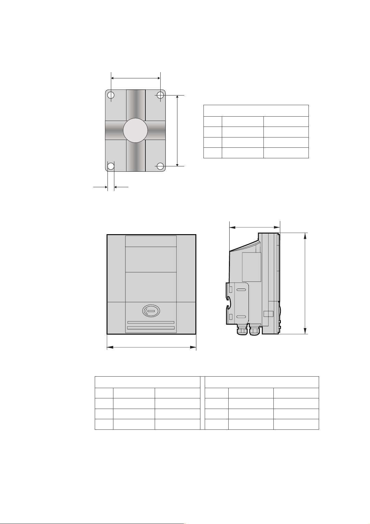
93
MFC 300 F Wall & Pipe Mount
Dimensions Weights
Dimensions
1
3
MFC 300 W
2
Item mm inches
1
60 2.4
2
100 3.9
3
@ 9 0.4
2
1
Item mm inches mm inches
1
198.3 7.8 2.4 kg 5.3 lb
2
138.1 5.4
3
298.7 11.8
3
Page 94

94
MFC 300 W Wall & Pipe Mount
Dimensions
2
1
3
4
8
6
7
D
Item mm inches mm inches
1
@ 9 @ 0.4
2
64 2.5
3
16 0.6
4
60.2
5
6
7
8
6.3 2.5
40.2
64 2.5
98 3.85
5
Page 95

95
Versions
Standard
C
F
W
R
Option
Measurements /
Measured variables
Diagnostic funct
ions
9.11 Technical Data
MFC 300
MFC 300
MFC 300
MFC 300
Interface (for all versions) Fieldbus Foundation and PROFIBUS PA and DP
EEx Versions ATEX EEx Zone 1 d + e + i
Approvals Custody transfer OIML R 117 (pending)
i
Compact Version
Field Housing Version
Wall Mount Version
19” Rack Version
FM Class I DIV 1 + 2
CSA Class I DIV 1 + 2
TIIS Zone 1 + 2(pending)
IECEX Ex Zone 1 + 2 (pending)
Nepsi Ex Zone 1 + 2
Units Metric, British or US units
Variables Mass Flow rate
Mass Total
Temperature
Density
Volume Flow rate
Volume Total
Velocity
Direction (this is not a display variable – though it can
be on an output)
Brix
Baume
NaOH
Plato
API General Purpose.
Concentration by Mass
Concentration by Volume
Standards meets and exceeds VDI / NAMUR / WIB 2650 (pending)
All versions with HART Display and operator
control elements.
Messages Output of messages optionally via display, current
and/or status output, and also HART® or bus interface
Sensor
Diagnostics
Sensor values
Drive level
Tube Frequency
MT Strain
IC Strain
SE/BE temperature
Page 96

96
Display and operator control
Output / input assemblies
Type Graphic display (backlit – white) 128 × 64 pixels / 59 × 31
mm
Display functions 4 pages (page through with )
pages 1-2:
•
optionally with one to three lines.
Each line can be set to show required measurement
value.
In a 2-line setting, the measured variable in the
1st line can be shown in the form of a bar graph in
the 2nd line.
Display ranges and number of places freely selec-
table.
Page 3: List of diagnostic and status messages
•
Page 4: Trend display
Counter places Max. 8
Language of
display texts
Operating
elements
Current outputs Function
Op. values and load
rating
Current Measuring range I
Overrange
Error identification
Forward / reverse
measurement
Automatic range or
external range
English, German, French, Spanish. Danish, Polish,
Portuguese, Dutch and others pending.
4 optical keys (
signal converter without opening the housing
Infrared interface for reading and writing all parameters
with KROHNE IR-Interface without opening the housing
For number and possible combinations of the various
outputs and inputs, refer to section. 9.7
Mass and volume flow rate, flow velocity, tempera-
•
ture, concentration, concentration flow, density,
diagnosis values
HART® interface is standard (but not for all option
•
modules), see section. 9.8
active or passive operation, dependent on the output
•
/ input assemblies, see section 9.8
Active
Passive
table as required
Setting: 0.00 mA
0 mA
Direction identified via status output, see below
via status output or control input, see below
a
22 mA / R
I
a
22 mA / U a 32 V DC
I
a
I
<
Err
) for operator control of the
>
g
1 kΩ
a
L
- I
min
value a21.5 mA
a
I
or I
min
max
between 0...20 mA set-
max
I
22 mA
a
<
Err
Time constant 0 - 100.0 s, settable as required
Low-flow cutoff Value: 0.0...20.0 %
Hysteresis: ± 0.0...20.0 %.
of Q
100%
as required
settable
Page 97

97
Pulse / frequency output
Status output
Control input
Internal electronic
counters
Function
Op. values and load
rating
When set as frequency output: Mass and volume flow
•
rate, flow velocity, temperature, concentration, concentration flow, density, diagnosis values
When set as pulse output: volume, mass, concentra-
•
tion (e.g. 1 pulse / m3 or / kg)
active or passive mode, dependent on the output /
•
input assemblies, see section 9.8
Active
NAMUR to EN 60947-5-6 (operating data as for “passive“)
f
10 kHz: I a20 mA / f a100 Hz: I a100 mA
a
U
24 V DC / U01.5 V @ 10 mA
nom
Pulse rate
Pulse width 0.05 ...2000 ms (autom., symm. or settable)
Forward / reverse
measurement
Time constant 0...100.0 s, settable as required
Low-flow cutoff Value: 0.0...20.0 % of Q
Function
Op. values and load
rating
Time constant 0...100.0 s, settable as required
0...10 kHz, scaleable (overflow up to fmax
Direction identified via status output, see below
100%
Hysteresis: ± 0.0...19.9 %
Error in device, application error, out of specification
•
error, polarity, overrange, counter preset
active or passive operation, dependent on output /
•
input assemblies, see section 9.8
Active
Passive
NAMUR to EN 60947-5-6 (operating data as for “passive“)
24 V DC/ I a100 mA / U0 a 1.5 V @ 10 mA
U
a
32 V DC/ I a100 mA / U0 a 1.5 V @ 10 mA
U
a
as required
12 kHz)
a
settable
Function
Op. values and load
rating
Number 3, settable independent of one another
Measured variable Total mass, volume or concentration
Function Sum + or – counter and preset counter
Time constant 0 - 100.0 s, settable as required
Low-flow cutoff Value: 0.0 - 20.0 % of Q100%, settable as
hold outputs, set outputs to zero, stop cpunters, count-
•
er reset, error reset, range change,
active or passive operation, dependent on output /
•
input assemblies, see section 9.8.
Active Inom = 16 mA / Unom = 24 V DC
Passive
NAMUR to EN 60947-5-6 (operating data as for “passive“)
Hysteresis:± 0.0 - 19.9 %.
32 V DC/ / Uon > 19 V DC / Uoff < 2.5 V DC
U
a
required
Page 98

98
Power supply AC Version DC Version AC/DC version
Housing
C
F
W
R
Degree of protection
C
F
W
R
Voltage range (without changeover) 100...230 V AC 12...24 V DC 24V AC 24V DC
Tolerance band -15% / +10 % -25 % / +30 % -15% / +10% -25% / +30%
Frequency 48...63 Hz N/A 48...63 Hz N/A
Max. power consumption (incl. sensor) 23 VA 14 W 25 VA 14 W
When connected to functional extra-low voltage (12 - 24 V DC), protective separation (PELV) must be
ensured (to VDE 0106 and IEC 364 / 536 or equivalent national regulations).
Compact: die-cast aluminium (optionally stainl. steel 1.4404)
Field housing die-cast aluminium (optionally stainl. steel 1.4404)
Materials
Ambient
Wall-mounted housing polyamide
19“ rack
in operation
aluminium section, stainless steel and aluminium sheet, in
part with polyester coating
-40…+60 °C / -40…149 °F
(-40…+55 °C / -40…131 °F for SS)
temperature
In storage -50…+70 °C / -58...+158 °F
(IEC 529 / EN
60 529)
Compact: IP 67 / NEMA 4X
Field housing IP 67 / NEMA 4X
Wall-mounted hsg IP 65 / NEMA 4 and 4X
19“ rack IP 20 / NEMA 1
Cable entry for Versions C, F and W M 20 × 1.5, ½“ NPT or PF ½“
Page 99

99
10
Display, operating and control elements
X’
START-UP
OPTIMASS
Before connecting to the power supply, check that the system has been correctly installed in
accordance with the relevant sections
The flowmeter, comprising sensor and signal converter, is delivered in a ready-to-operate condition. All operating data have been factory-set according to your order specifications and reference should be made to the report on settings which is supplied.
After switching on the power, a self-test is carried out, after which the flowmeter immediately
starts flow measurements and displays the current measured values.
Alternating between the 1stand 2ndmeasured value window and, if provided, the list of status
messages is carried out by actuating key or Possible status messages, their meaning and
possible cause are listed in the Status Table in section 10.5
10.1 Operator Control of the Signal Converter
1
9
8
7
6
1 Blue bar indicates:
The tag number.in the measuring mode
The menu/ function name in the setting mode
indicates actuation of a key
2 ‘
indicates IR transmission in operation; the 4 optical keys then have no function
2
3
4
5
3 Graphics display, backlit (white)
4 Optical interface for wireless transfer of data (input / output)
5 Socket for connection to the KROHNE GDC bus
6 Optical keys for operating the signal converter without opening the housing
7 3rd display line, shown here as bar graph
8 1st and 2nd display line to indicate different measured variables
Shown here in large format for only one measured variable
9 signals a status message in the status list
Page 100

100
13
12
15
14
11
10
1
13
15
1
2
1
1 indicates status messages, if any
2 Marker indicates position in the menu/function lists
3 Higher-level menu (with No. in Setup Menu only)
4 Indicate beginning and end of menu/function lists
5 Current menu
6 Not indicated in Menu Mode
7 Next selectable menu
8 Current menu/function (with No. only in Setup Menu)
9 Indicator for factory settings
9
Factory setting (for info only, unalterable) of current (sub-) function to be changed
Current (sub-) function
Currently set value, unit or function (when selected,shown as white characters on blue
background)
Indicator for allowable range of values
Allowable range of values, only in case of numerical values or next function
Indicator for changing a (sub-) function; allows simple check of changed data when scrolling through the (sub-) function lists.
 Loading...