

Page 1
Handbook
KROHNE 06/05 7.02233.24.00
©
Installation and operating
handbook
Optimass Series of Mass Flowmeters and
050/051 Converters
Subject to change without notice
Electromagnetic flowmeters
Variable area flowmeters
Mass flowmeters
Ultrasonic flowmeters
Vortex flowmeters
Flow controllers
Level measuring instruments
Pressure and temperature
Heat metering
Communications technology
Switches, counters, displays and recorders
Engineering systems & solutions
Page 2

Page 3

Contents
1 MECHANICAL INSTALLATION 6
1.1 General principles 6
1.1.1 Transport and Lifting
1.2 OPTIMASS 7000 Single Straight Tube Meter
1.2.1 Specific Installation Guidelines 9
1.2.2 Ambient / Process temperatures
1.2.3 Pressure Equipment Directive (PED) requirements
1.2.4 Secondary Pressure containment
1.2.5 Pressure de-rating
1.2.6 Hygienic Applications
1.2.7 Heating and insulation
1.2.8 Purge Port Meters and Burst Disk Meters
1.2.9 Technical Data
1.2.10 Weights & Dimensions
1.3 OPTIMASS 3000 (7100) Single Z Shaped Tube Meter
1.3.1 Specific Installation Guidelines
1.3.2 Ambient / Process temperatures
1.3.3 Pressure Equipment Directive (PED) requirements
1.3.4 Secondary Pressure containment
1.3.5 Pressure de-rating
1.3.6 Heating and insulation
1.3.7 Purge Port Meters and Burst Disk Meters
1.3.8 Technical Data
1.3.9 Weights & Dimensions
1.4 OPTIMASS 8000 / 9000 Meter with Twin U Measuring Tubes
1.4.1 Specific Installation Guidelines 30
1.4.2 Ambient / Process temperatures
1.4.3 Pressure Equipment Directive (PED) requirements
1.4.4 Secondary Pressure containment
1.4.5 Pressure de-rating
1.4.6 Hygienic Applications
1.4.7 Heating and insulation
1.4.8 Purge Port Meters and Burst Disk Meters
1.4.9 Technical Data
1.4.10 Weights & Dimensions
2 ELECTRICAL INSTALLATION
2.1 Location and connecting cables
2.2 Connection to power
2.2.1 Power Supply Wiring MFC050
2.2.2 Power Supply Wiring MFC051 Non Ex
2.2.3 Power Supply Wiring MFC 051 Ex
2.3 Connection of remote meters
2.4 Hazardous Area requirements
2.5 Inputs and outputs
2.5.1 Inputs/Outputs MFC 050
2.5.2 Inputs / Outputs MFC051
2.6 Compact to Remote / Remote to Compact conversion instructions
2.7 Technical Data
2.7.1 MFC050
2.7.2 MFC051
3 START-UP
3.1 Factory Set Parameters
3.2 Initial Start-up
3.3 Zero point adjustment
3.4 Programming the converter with a bar magnet
10
10
13
14
18
19
20
23
23
24
24
25
25
26
26
27
28
30
30
30
31
31
33
34
35
35
35
39
39
39
39
39
40
40
41
41
41
46
48
48
48
49
50
50
50
51
51
8
9
9
9
Installation and Operating Instructions OPTIMASS
2
Page 4

4 PROGRAMMING THE CONVERTER MFC 050/051 52
4.1 Operating and check elements 52
4.2 OPTIMASS MFC 050/051 Operating Concept
4.3 Key functions
4.3.1 How to enter programming mode
4.3.2 How to terminate Programming mode
4.4 Table of programmable functions
4.5 Reset / Quit Menu - Totalizer reset and status indication acknowledgement
5 DESCRIPTION OF FUNCTIONS
5.1 Menu 1 - Initial Start up 68
5.2 Menu 2 – Functional Checks
5.3 Menu 3- Configuration Menu
5.4 Menu 4 - I/O Configuration
5.5 Menu 5 - Factory Settings
6 SERVICE AND TROUBLE SHOOTING
6.1 Diagnostic functions
6.2 Error Messages
6.3 Functional Tests and Troubleshooting
6.4 Replacing the Front End or Back End Electronics
6.4.1 Replacing the Front End
6.4.2 Replacing the Back End
6.5 Spares
7 EXTERNAL STANDARDS AND CODES
7.1 Standards 101
7.1.1 Mechanical
7.1.2 Electrical
7.2 Declaration of Conformity
7.3 PED Certificate
8 DEVICE CONFIGURATION SHEET
9 DECLARATION OF CLEANLINESS CERTIFICATE 107
53
54
55
55
58
67
68
74
78
86
91
93
93
94
95
97
97
98
99
101
101
101
102
103
105
Installation and Operating Instructions OPTIMASS
3
Page 5

How to use these installation and operating instructions
Congratulations on purchasing this high quality product. To get the best out of your mass flowmeter,
please take some time to read through the instructions.
This instruction handbook is comprehensive and describes the many features and options available
with this mass flow meter.
Please refer to the index for a list of detailed topics.
Note:
If applicable, a separate document is supplied that describes all ATEX hazardous area information.
Product liability and warranty
The OPTIMASS mass flow meter family is designed for the direct measurement of mass flow rate,
product density and product temperature, and also indirectly enables measurement of parameters such
as total mass, concentration of dissolved substances and the volume flow.
For use in hazardous areas, special codes and regulations are applicable which are specified in the
section on Hazardous Area Installations.
Responsibility as to suitability and intended use of our instruments rests solely with the
purchaser. The supplier does not accept any liability resulting from misuse by the customer.
Improper installation and operation of the flow meters may lead to loss of warranty. Warranty is also
null and void if the instrument is damaged or interfered with in any way.
In addition, the “general conditions of sale” which forms the basis of the purchase agreement are
applicable.
If you need to return OPTIMASS flow meters to KROHNE, please complete the form on the last page
of the installation and Operating manual and return it with the meter to be repaired. KROHNE regrets
that it cannot repair or check your flow meter unless accompanied by this completed form.
CE / EMC Standards /Approvals
• The OPTIMASS family with the MFC 050 / 051 / 010 signal converter meets all the requirements of
the EU-EMC and PED Directives and bears the CE Symbol.
• The OPTIMASS system is approved for hazardous duty installations to the harmonised European
Standards (ATEX) to Factory Mutual (FM) and CSA (Canadian Standards).
Technical data subject to change without notice
Installation and Operating Instructions OPTIMASS
4
Page 6

Unpacking the meter
When unpacking your meter, please ensure that no visible damage has occurred during
transportation. If damage has occurred, please contact the carrier for claims.
Your high quality instrument has been fully tested and checked before shipping. The following
items should be included with your instrument unless otherwise requested:
1. Mass Flow Meter OPTIMASS
2. Separate Converter with remote converter wall mount (not for compact version)
3. CD-ROM & Quick Start Guides
4. Spanner to open the electronic housing lids
5. Bar magnet for programming the meter
6. Screw driver for terminal connections
7. Calibration certificate
8. Factory and Material certification, if ordered.
If any of these items are missing, please contact your nearest KROHNE Office or representative
(see back page).
Attention:
Please read the Handbook before installing the meter.
Many problems are avoided when the simple guidelines in this handbook are followed.
Installation and Operating Instructions OPTIMASS
5
Page 7

1 Mechanical Installation
1.1 General principles
The OPTIMASS mass flow meters provide high accuracy and excellent repeatability. Narrow band pass
digital filtering, and the mathematically modelled internal primary head design with AST (Adaptive Sensor
Technology) for the OPTIMASS sensor family provide exceptional immunity to external vibratory
disturbances from nearby process equipment.
The accuracy of the flow meter is not affected by velocity profile.
The following installation guidelines are practical to implement, particularly if planned before the
OPTIMASS meter is first installed. For further dimensions or connections, please refer to the relevant
section.
For the OPTIMASS, in general, no special mounting requirements are necessary. However, good general
engineering practice for the installation of flow meters should still be observed.
The general guidelines described in this section are valid for the complete OPTIMASS family of mass flow
meters.
• The mass flow meters do not require any straight inlet or outlet runs.
• Due to the weight of the meters we recommend the use of supports.
• It is permissible to support the body of the meter.
• The meter can be installed horizontally, in an upward sloping pipeline or vertically. For best results, a
vertical installation with flow in an upward direction is recommended.
This label on the meter shows the flow direction programmed into the converter in function 3.1.4.
As default this is always in the direction of the ‘+’ arrow, i.e. left-to right as the label is viewed.
Installation and Operating Instructions OPTIMASS
6
Page 8
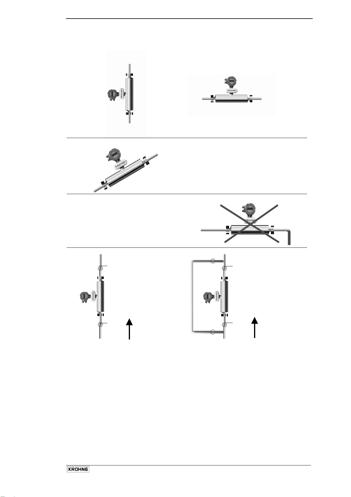
Examples
Vertical mounting Horizontal mounting
Upward sloping installation
Avoid mounting the meter with long vertical
drops after the meter. This could cause
siphoning and cause measurement errors.
Avoid mounting the meter at the highest point in
the pipeline. Air or gas can accumulate here and
cause faulty measurements
1
1
2
Flow
2
Flow
1 Valve for zeroing flow meter
2 The second valve is recommended if the pump is switched off to prevent reverse flow
To enable a good zero to be done, it is recommended that a shut-off valve be installed downstream
of the flow meter.
Installation and Operating Instructions OPTIMASS
7
Page 9
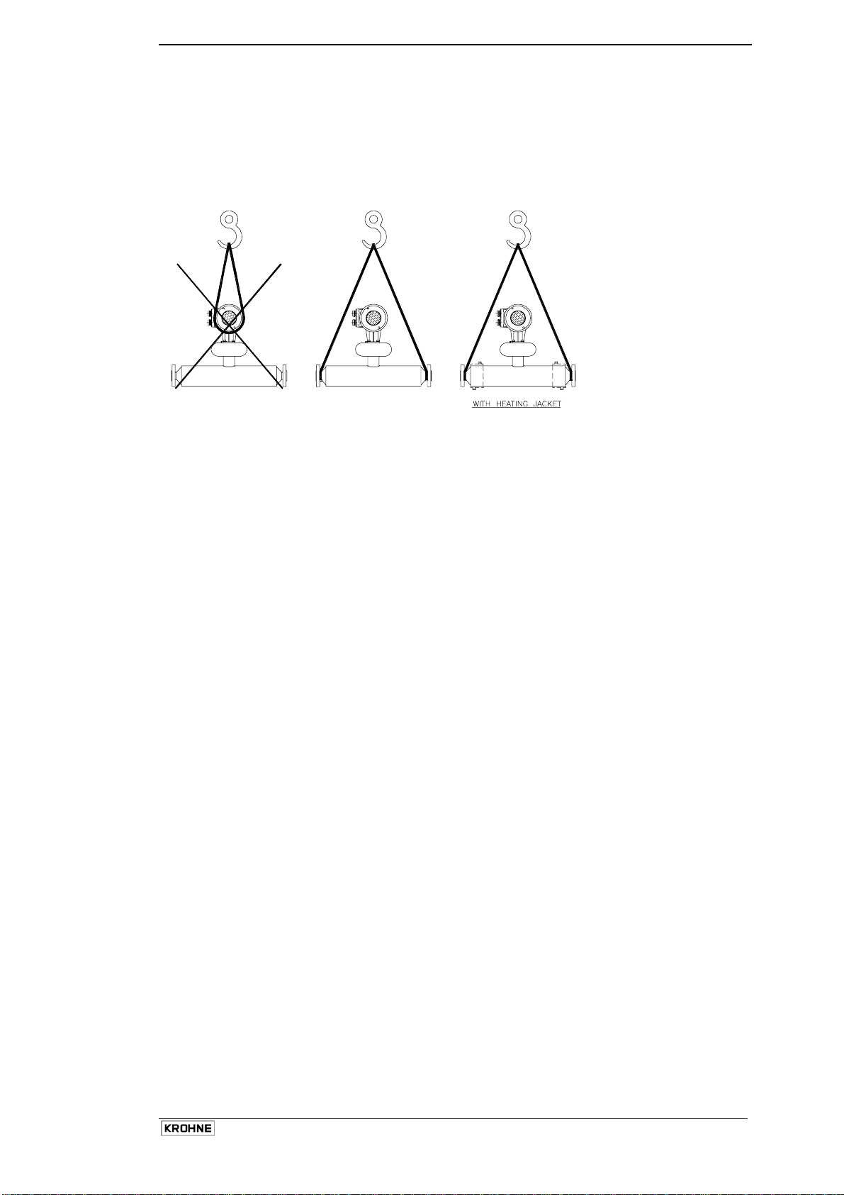
1.1.1 Transport and Lifting
As the larger meters are heavy, care should be taken when lifting to install.
• Meters should be lifted or suspended using a well maintained sling.
• The meters should under no circumstances be lifted by the electronics housings.
• The meters can be lifted and suspended from the spigots as shown.
Installation and Operating Instructions OPTIMASS
8
Page 10
1.2 OPTIMASS 7000 Single Straight Tube Meter
1.2.1 Specific Installation Guidelines
• Tighten flange bolts evenly.
• Observe min and max pipe end loads at end of this section.
The use of reducers at the flanges is
allowed. Extreme pipe size reductions
should be avoided due to possibility of
cavitation and degassing.
There are no additional installation requirements for the OPTIMASS 7000 sensors. Fixing of flexible
hoses directly on the meter is allowed.
1.2.2 Ambient / Process temperatures
The specified and approved ambient and process temperatures must be observed.
Titanium HC22 SS318L
°C °F °C °F °C °F
Process -40 .. +150 -40 .. +300 0 .. +100 0 .. 212 0 .. +100 0 .. 212
-20°C or 4°F for hygienic
or aseptic connections
Ambient
Compact
-40 .. +55 -40 .. +130 -40 .. +55 -40 .. +130 -40 .. +55
Remote
-40 .. +60 -40 .. +140 -40 .. +60 -40 .. +140 -40 .. +60
-40 ..
+130
-40 ..
+140
Note:
Where meters are mounted in direct sunlight, it is recommended to install a sunshade. This is
particularly important in countries with high ambient temperatures.
The maximum differential temperature between the process and ambient temperature without
insulation is 130°C or 265°F for Titanium and 80°C or 115°F for Hastelloy and Stainless Steel meters.
1.2.3 Pressure Equipment Directive (PED) requirements.
To comply with the requirements of the PED in Europe, the following information is provided to assist
the plant engineer in installing the meter.
Measuring tube: Titanium Grade 9 Sealing Faces: Titanium Grade 2
Hastelloy C22 Hastelloy C22
Stainless SS 318 Stainless SS 318
The outer cylinder (Secondary Pressure containment) 304 / 304L is dual certified and with “0” rings in
pairs of Viton and hydrogenated nitrile. (Optional outer cylinder of 316/316L).
Wiring feedthrough is made of Epoxy.
Flanges all 316 / 316 L dual certified.
Optional heating jacket 316 / 316L.
Note :
Outer cylinder is in contact with heating medium.
Installation and Operating Instructions OPTIMASS
9
Page 11
1.2.4 Secondary Pressure containment
The OPTIMASS 7000 meters are supplied with secondary pressure containment as standard.
Allowable maximum secondary containment pressures are 63 bar at 20°C or 914 psig at 70°F
If the user suspects that the primary tube has failed, the unit must be depressurised and removed
from service as soon as possible.
Note:
In the 7000 Series there are high pressure feed through seals and ‘O’ rings that might not be
compatible with the process fluid for an extended period if a primary tube fails.
It is important to remove the meter ASAP
It is the user’s responsibility to ensure that the materials used are compatible with this product.
Other ‘O’ ring materials are available on request.
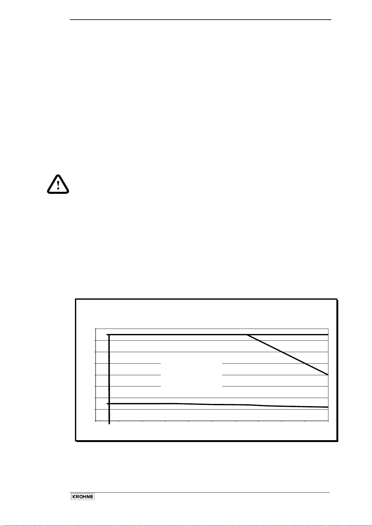
1.2.5 Pressure de-rating
Meter data plates are stamped with maximum pressure rating (at max. operating temperature) of
connection, primary tube or secondary pressure containment (whichever is the lower). Higher
pressures may be possible at lower temperatures.
Titanium Tubes and secondary pressure containment is 63 bar at 20°C or 910 psi at
4°F
De-rated to 40 bar at 150°C or 580 psi at
300°F
The titanium tubes could handle a higher pressure, but where this exceeds the pressure rating, a relief
or bursting disk has to be fitted to the secondary pressure containment. This can be done as a
special. (This is available for meter sizes up to 25 only)
Hastelloy and SS measuring tubes are rated for 50 bar at 20°C or 725 psi at
4°F
De-rated to 40 bar at 100°C or 580 psi at
210°F
Heating Jacket 10 bar at 100°C or 145 psi at
210°F
Pressure Derating
Pressure/Temperature de-rating for Titanium Gr.9
Metric PN 40 & PN63
70
65
60
55
50
45
40
35
30
Pressure in Bar
25
20
15
10
5
0
-50 0 50 100 150
DN80 PN63, DN100 PN63
Flange
DN100 PN40 Flange
Temperature/deg. C
Secondary Press. Containment 304 L
DIN 2501
PN 40 Flange
Secondary Press. Containment 316 L
&
DIN 2501
PN 63 Flange
Installation and Operating Instructions OPTIMASS
10
Page 12
Pressure/Temperature de-rating for SS and Hast. C22
Metric DIN 2501 PN 40
70
65
60
55
50
45
40
35
DN100 PN40 Flange
30
Pressure (bar)
25
20
15
10
5
0
0 102030405060708090100
Temperature Deg. C
Secondary Pressure
Containment 304 L
and flanges
DIN 2501 PN 40
Secondary Pressure
Containment 316 L
Pressure/Temperature de-rating for Titanium Gr.9
ANSI 150/300/600 lbs
1000
900
800
700
600
500
400
Pressure in psi
300
200
100
0
-50 0 50 100 150 200 250 300 350
ANSI 300 lbs
Secondary Pressure
containment 304 L
ANSI 150 lbs
Temperature/deg. F
Secondary Pressure
containment 316 L
& ANSI 600 lbs
Installation and Operating Instructions OPTIMASS
11
Page 13
Pressure/Temp erat ure de-ratin g for SS an d Hast. C22
950
900
850
800
750
700
650
600
550
500
450
400
Pressure in p si
350
300
250
200
150
100
50
0
30 50 70 90 110 130 150 170 190 210
ANSI 300 lbs
Secondary Pressure
ANSI 150 and 300 l bs
Temperature in Deg. F
ANSI 150 lbs
Secondary Pressure
Containment 316 L
Maximum pipe work forces
The maximum forces exerted on the meter from the pipe work, compressive or tensile has been
calculated for the 7000 Series (Straight tube meter) with Titanium, Hastelloy and SS measuring tubes
as follows:
Titanium
Size Max Force:
Flanges
Max Force:
Hygienic Connectors
06 T 19 KN 1.5 KN
10 T 25 KN 2 KN
15 T* 38 KN 5 KN
25 T 60 KN 9 KN
40 T 80 KN 12 KN
50 T 170 KN 12 KN
80 T 230 KN 30 KN
*On OPTIMASS 15 T with ½” ANSI flanges only – maximum end load is 19 KN.
Hastelloy and SS
Size Max Force:
Flanges
Max Force:
Hygienic Connectors
06 S 19 KN 1.5 KN
10 H/S 25 KN 2 KN
15 H/S* 38 KN 5 KN
25 H/S 60 KN 9 KN
40 H/S 80 KN 12 KN
50 H/S 80 KN 12 KN
80 H/S 170 KN 18 KN
*On Optimass 15 H or S with ½” ANSI flanges only – maximum end load is 19 KN
Loads given in both tables are maximum static loads. If loads are cycling, particularly between tension
and compression then these loads should be reduced.
Please consult KROHNE for more information.
Installation and Operating Instructions OPTIMASS
12
Page 14
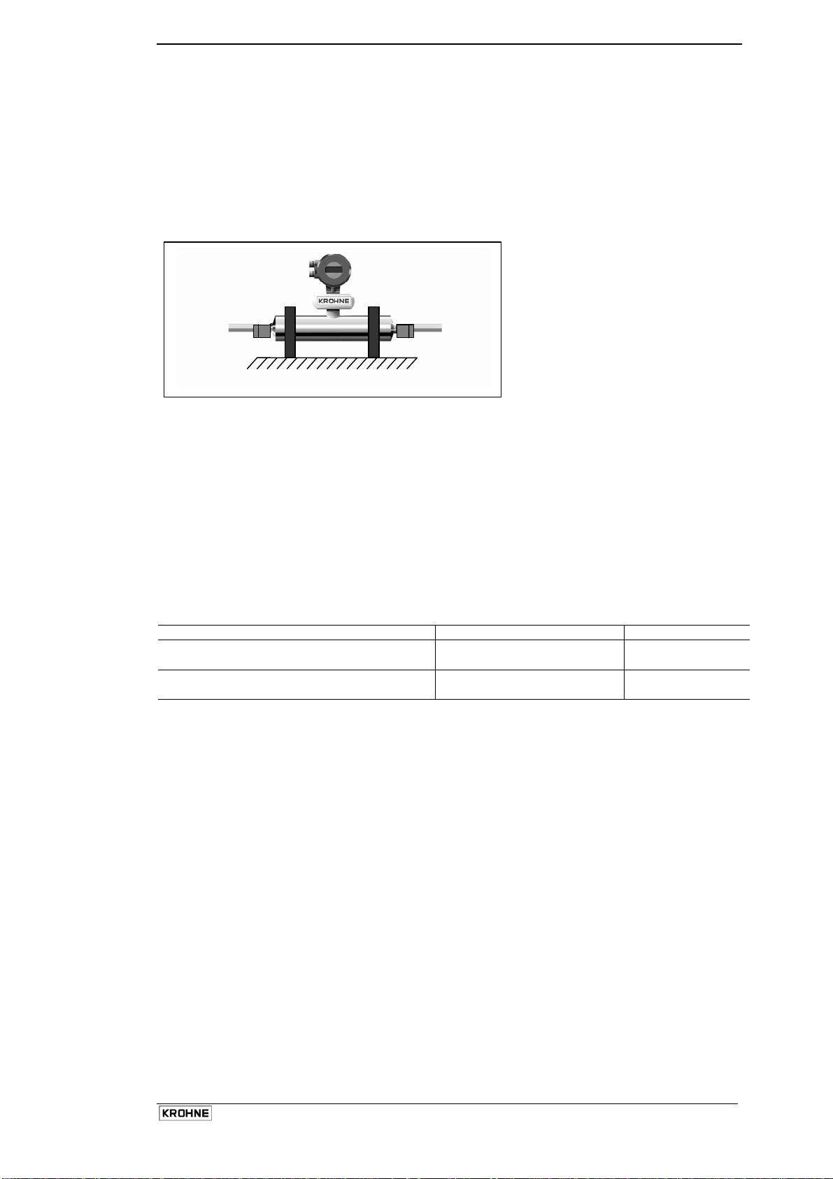
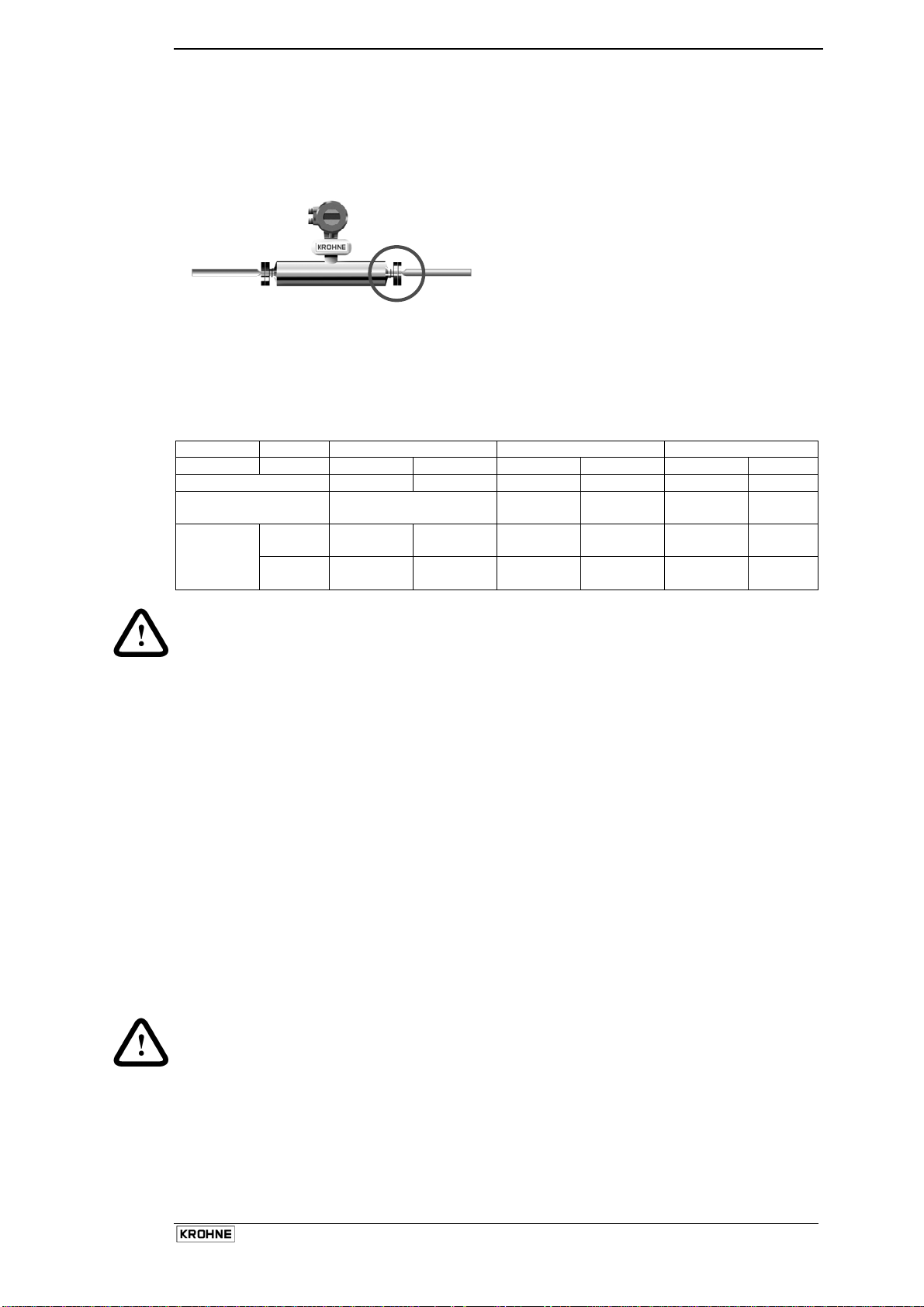
1.2.6 Hygienic Applications
The OPTIMASS 7000 series is available with a variety of hygienic process connectors.
When using / installing meters with hygienic process connectors, care should be taken to ensure the
meter is well supported / clamped, as the meters are heavy and could injure when disconnected from
the adjacent pipe work.
The recommended method of installation is to mount the meter against a support / wall with the body of
the meter supported / clamped. The process pipe work can then be supported off the meter. The meter
is too heavy to be supported from the thin walled piping usually associated with the hygienic industry.
Meter supported from its body
Installation lengths
For installation lengths, please see section 1.2.10
Please check with KROHNE if you are unsure of the installation length. Many meters are built to
customer requirements / specifications especially where special hygienic process connectors have been
adapted to the meter. As these are normally non-standard, the installation length will not be given in the
technical data.
It is also recommended that the seals be replaced regularly to maintain the hygienic integrity of the
connection.
Hygienic Connection Materials
Version Titanium Meter SS 318 Meter
All welded DIN 11864
Titanium Grade 2 SS 318
All welded Tri-Clamps
Adaptor versions 316L Stainless Steel 316L Stainless Steel
EPDM seals EPDM seals
Unless specifically requested, internal surfaces are not polished and no warranty is made as to the
surface finish. If polishing option and /or EHEDG, ASME Bio-Processing or 3A approvals was selected
at time of order, all product contact surfaces are polished 0.5 micrometer Ra (Ra 20) finish or better.
Use of OPTIMASS 7000 SS sensors above 100°C – Hygienic Connections only
Sizes 25S, 40S, 50S and 80S sensors with hygienic connections may be exposed to temperatures
above 100°C up to a maximum of 130°C for a maximum of 2 hours (e.g. for steam cleaning purposes).
The maximum temperature shock permitted either from cold to hot or from hot to cold is 110°C.
E.g. A meter measuring a product at 20°C can be immediately steam cleaned at 130°C, but a meter
measuring a product at 5°C can only be immediately steam cleaned at 115°C. Conversely, after steam
cleaning at 130°C the minimum allowed temperature of the product introduced immediately afterwards is
20°C.
Operation outside of these guidelines may cause shifts in the mass flow and density calibration.
Repeated shocking may also cause premature failure of the meter.
Installation and Operating Instructions OPTIMASS
13
Page 15
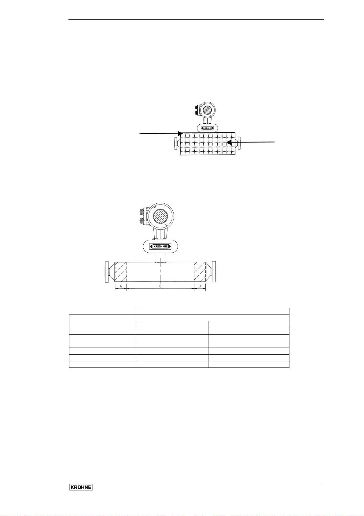
1.2.7 Heating and insulation
There are several methods to heat the meter. In most cases heating is unnecessary as the meter is
designed as such that very little heat is lost or gained through the outer cylinder.
Insulation
Where insulation is required a variety of materials may be used to insulate the meter. Care must be
taken not to insulate the meter above the halfway mark of the electronics support post as shown in the
sketch.
Do not insulate above
this line.
Insulation
Electrical Heating
Electrical tape heating may be used. Care should be taken to only heat the sections where the best
effect will be achieved. Do not heat above the converter mount centre line as shown above.
The following guidelines must be observed.
Areas A and B may be
heated. Area C must not be
heated.
When insulating please observe guidelines as per insulation section.
DIM A and B Size
Titanium Hastelloy + SS 318
10 50 15 65 65
25 120 75
40 150 150
50 200 125
80 410 225
Installation and Operating Instructions OPTIMASS
14
Page 16
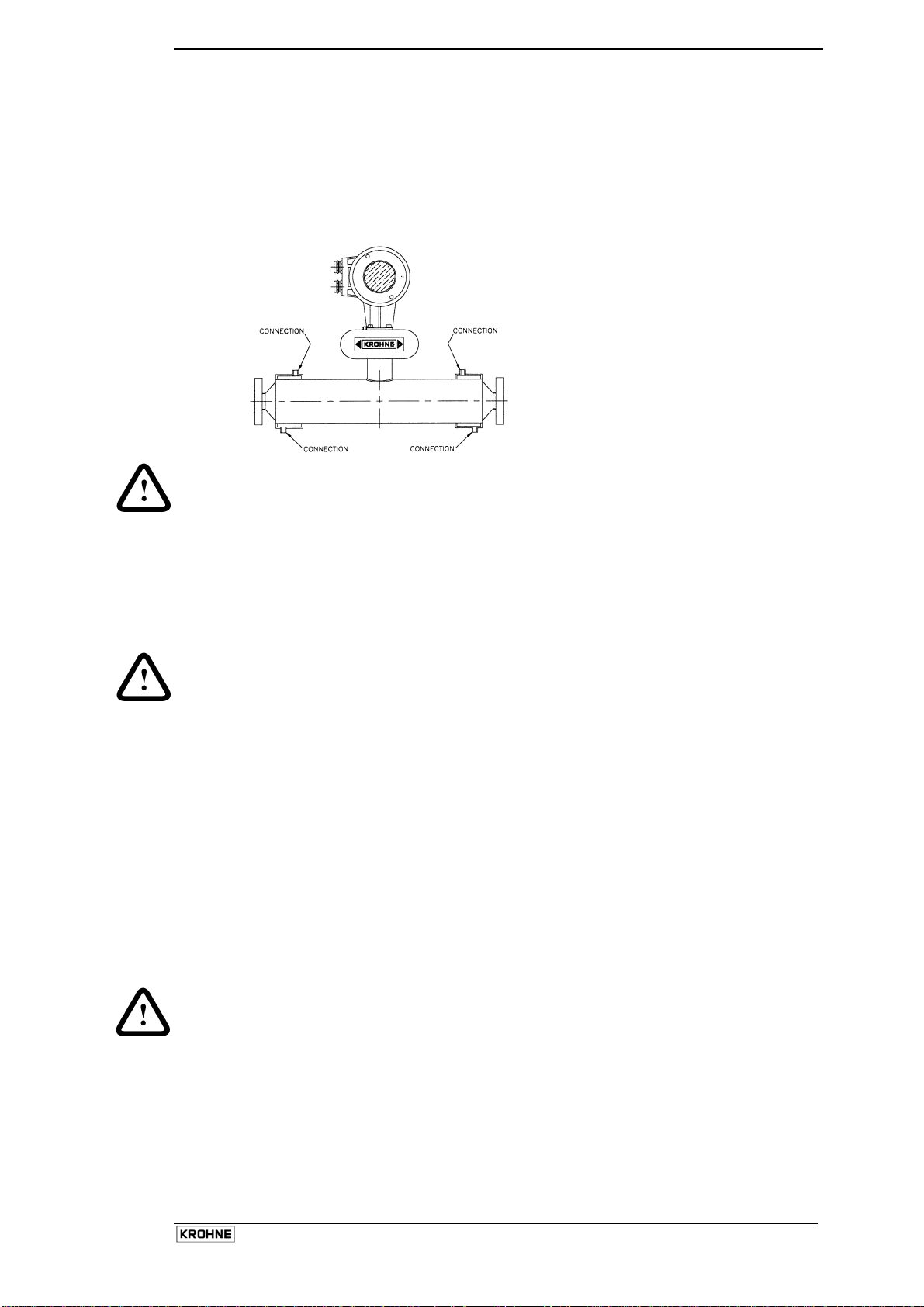
Liquid / Steam heating jacket
The meter can be supplied with a heating jacket. This jacket is designed to minimise the differential
stress across the meter where differences in temperature between outer cylinder and measuring tube
exist.
The connections to the heating jacket are NPT or Ermeto sockets.
It is recommended that reinforced flexible hoses be used to connect the heating jacket to the heat
source.
Important:
Always heat jacket to working temperature before flowing product in measuring tube.
It is important to avoid the use in the heating jackets of fluids which cause crevice corrosion.
Regarding jacket materials. Although all the jacket materials are 316L, the outer cylinders are 304L
(Optional 316L).
Connections should be made to ensure all air can be vented on liquid systems and all condensate can
be drained on steam systems.
Note :
Max heating medium pressure and temperature for heating jackets is 10 bar at 150°C or 145 psig at
300°F for titanium measuring tubes and 10 bar at 100°C or 145 psig at 210 °F for Hastelloy and
Stainless Steel measuring tubes.
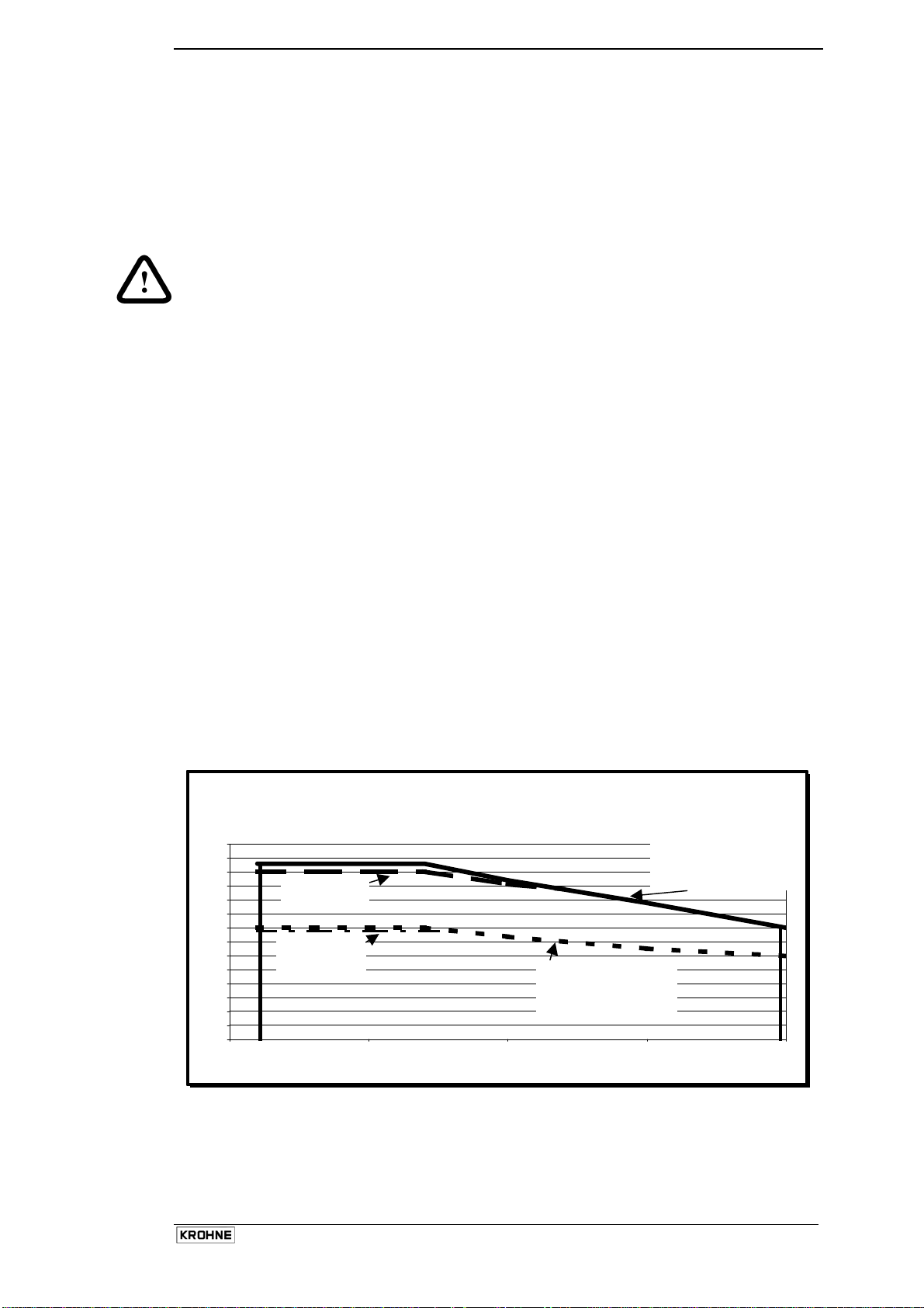
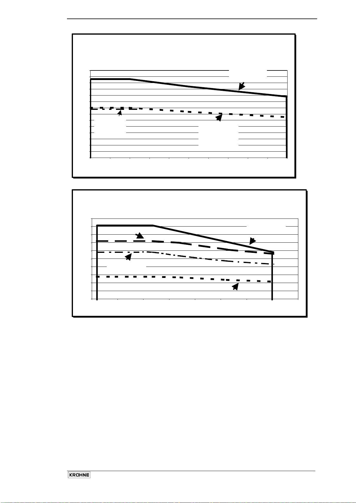
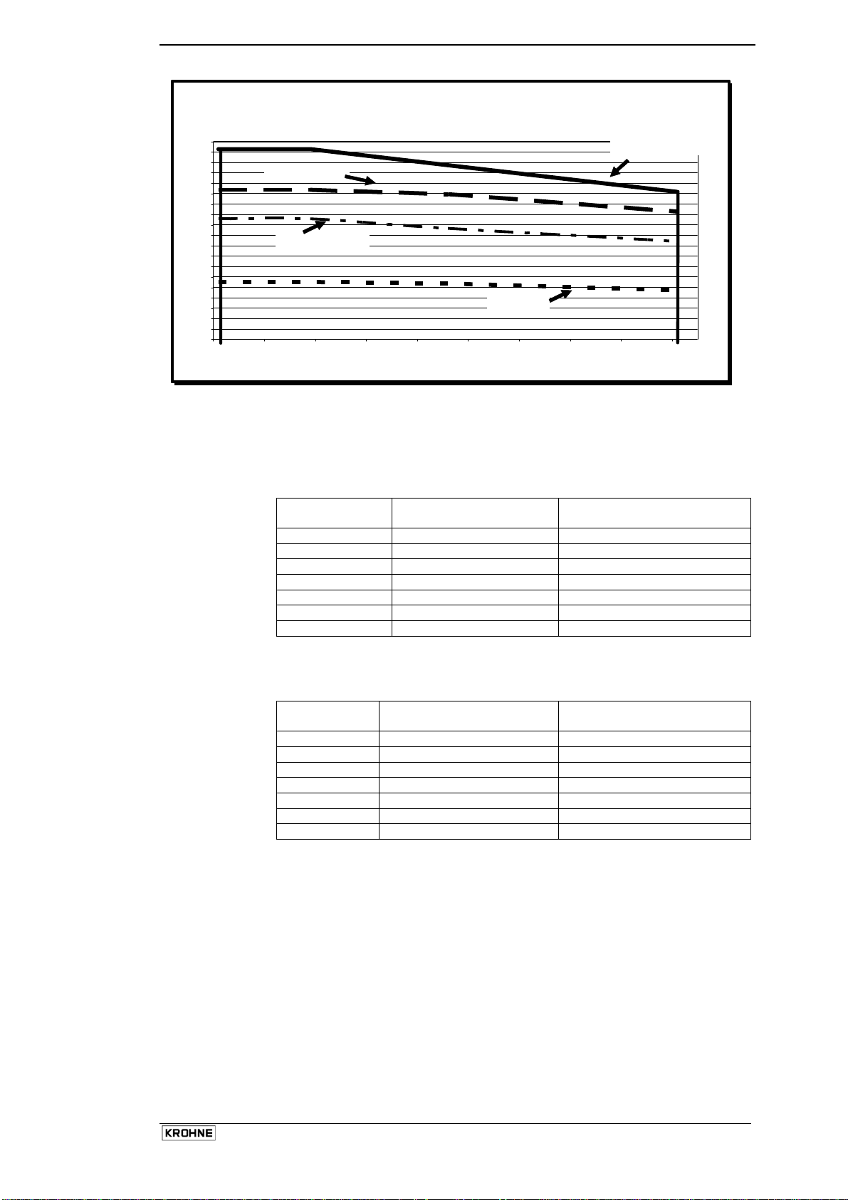
Heating Times
The following graphs are provided as a guide only. Heating times were calculated and tested using the
following conditions:
• Ambient temperature 25°C or 80°F
• Meter insulated.
The Titanium meters were heated using a steam temperature of 150°C or 300°F and the Hastelloy and
Stainless Steel meters using a temperature of 100°C or 210°F.
Heating times may vary depending on the quality of insulation (if any), ambient temperature and
temperature of the heating medium. Once meter has been heated to a temperature where the product
will not solidify, product may be introduced if required. This will bring the meter to operating temperature
sooner.
Note:
The maximum heating temperature for a Titanium meter is 150°C or 300°F.
The maximum heating temperature for Hastelloy or SS meters is 100°C or 210°F.
If these temperatures are exceeded, the meter will be damaged.
KROHNE accepts no responsibility if this happens.
Installation and Operating Instructions OPTIMASS
15
Page 17
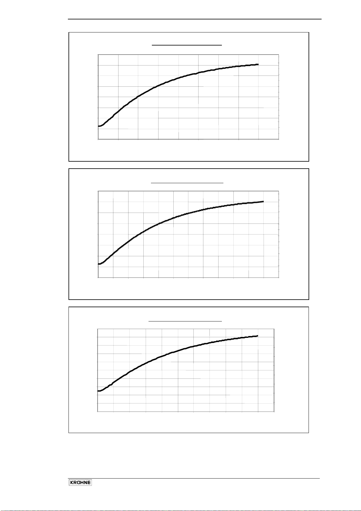
OPTIMASS T10 to T25 - Heating Times
160.0
140.0
120.0
100.0
80.0
60.0
40.0
Measuring Tube (centre) temperature (°C)
20.0
0.0
0.00
1.00
2.00
3.00 4.00 5.00 6.00 7.00 8.00
312
292
272
252
232
212
192
172
152
132
112
92
Measuring Tube (centre) temperature (°F)
72
52
9.00
32
OPTIMASS T 40 to T 80 - Heating Times
160.0
140.0
120.0
100.0
80.0
60.0
40.0
Measuring Tube (centre) temperature (°C)
20.0
0.0
0.00 2.00 4.00 6.00 8.00 10.00 12.00 14.00 16.00 18.00 20.00 22.00 24.00
Time (hours)
310
290
270
250
230
210
190
170
150
130
110
90
70
50
30
Measuring Tube (centre) temperature (°F)
OPTIMASS H & S15 to 25 Heating Times
100.0
90.0
80.0
70.0
60.0
50.0
40.0
30.0
20.0
Measuring Tube (centre) temperature (°C)
10.0
0.0
0.00 1.00 2.00 3.00 4.00 5.00 6.00 7.00 8.00 9.00 10.00 11.00
Time (hours)
212
192
172
152
132
112
92
72
Measuring Tube (centre) temperature (°F)
52
32
Installation and Operating Instructions OPTIMASS
16
Page 18
)
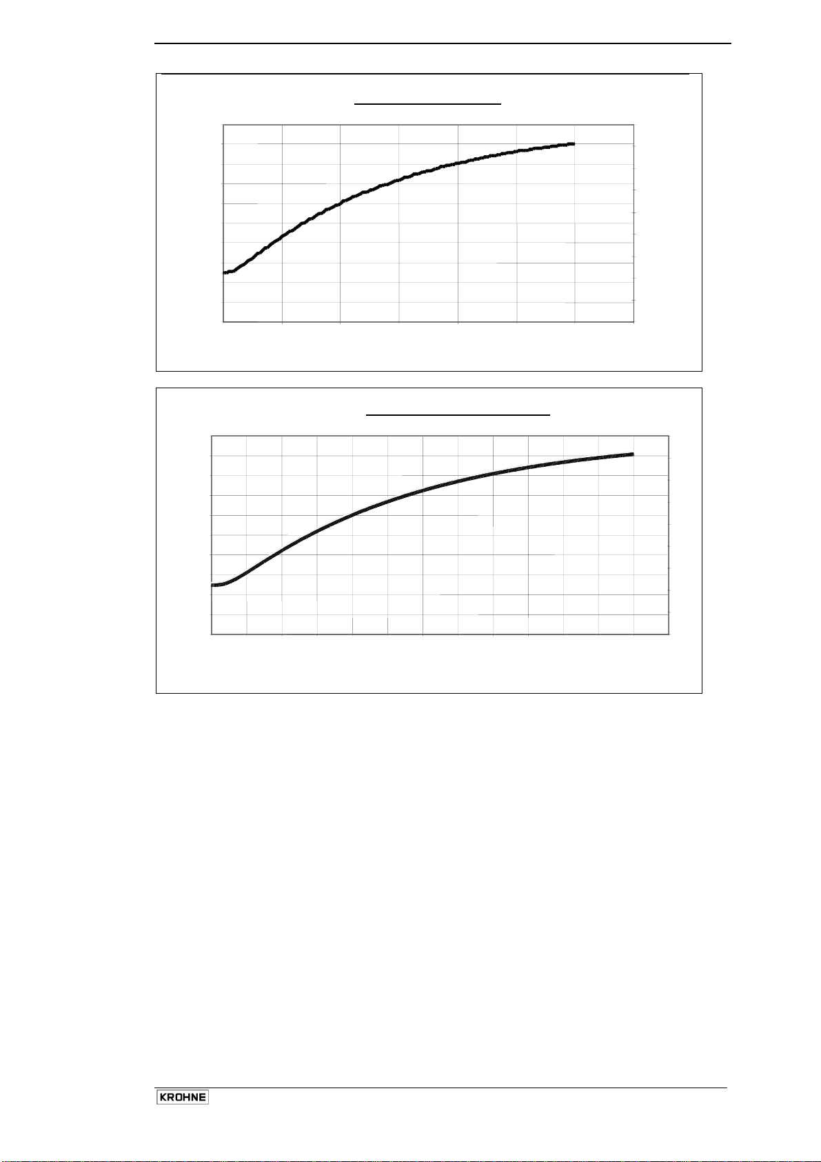
OPTIMASS H & S 40 Heating Time
100.0
90.0
80.0
70.0
60.0
50.0
40.0
30.0
20.0
Measuring Tube (centre) temperature (°C)
10.0
0.0
0.00
2.00
4.00 6.00 8.00 10.00 12.00
Time (hours)
14.00
212
192
172
152
132
112
92
72
52
32
Measuring Tube (centre) temperature (°F)
OPTIMASS H & S 50 to 80 Heating Times
100.0
90.0
80.0
70.0
60.0
50.0
40.0
30.0
20.0
Measuring Tube (centre) temperature (°C)
10.0
0.0
0.00 2.00 4.00 6.00 8.00 10.00 12.00 14.00 16.00 18.00 20.00 22.00 24.00 26.00
Time (hours
210
190
170
150
130
110
90
70
Measuring Tube (centre) temperature (°F)
50
30
Cooling
Please consult KROHNE if cooling medium is to be used in the heating jacket.
Installation and Operating Instructions OPTIMASS
17
Page 19
1.2.8 Purge Port Meters and Burst Disk Meters
Purge Port Options
If the purge port option was selected at time of order, then your meter will be fitted with ½” NPT female
connections – these will be clearly identified. These connections are sealed with NPT plugs and PTFE
tape.
Important:
Do not remove these plugs.
The meter is factory sealed with a dry nitrogen gas fill and any ingress of moisture will damage the meter.
The plugs should only be removed to purge the inside of the meter case of any product if it is suspected
that the primary measuring tube has failed. This must only be done after the meter has been
depressurised and removed from service. This should be done as soon as possible after failure is
suspected (less than 3 days)
Burst Disk meters (Meters up to size 25 only)
OPTIMASS 7000 meters that have been ordered with a bursting (rupture) disk will be so fitted. This is
fitted when the operating pressure of the measuring tube exceeds the design pressure of the secondary
containment. The disk failure pressure is 20bar @ 20°C.
Important:
The burst disk is suitable for the designed application according to the process conditions and flow rates
as per original order. If conditions alter, consult KROHNE for further advice regarding suitability of disk
fitted.
If the product is in any way hazardous, it is strongly recommended that an exhaust tube is connected to
the NPT male thread of the burst disk so that the discharge can be piped to a safe area. This tube should
be large enough that pressure cannot build up in the meter case.
Ensure arrow on burst disk is pointing away from meter.
Installation and Operating Instructions OPTIMASS
18
Page 20

1.2.9 Technical Data
Nominal Flow Rates
06 10 15 25 40 50 80
Kg/h
Lbs/min
950 2,700 11,250 34,500 91,500 180,000 430,000
35 100 400 1,250 3,350 6,600 15,800
Maximum flow rate
Typically 130 % of the nominal flow rate for the sensor size depending on application.
Minimum flow rate
Depending on measuring error required.
Tube materials:
• Titanium Gr. 9,
• Hastelloy C22 and
• SS 318.
The meter size has a prefix T, H, or S indicating the tube material.
Secondary pressure containment
• All 70 Series meters have secondary containment rated to 40 bar or 580 psi.
• An optional 63 bar or 914 psi is available.
Materials of construction
• Flanges: SS 316 L
• Spigots and outer cylinder: SS 304 L optional SS 316 L
• Front end housing and post: SS 316 L
• Converter housing: Epoxy coated aluminium
Installation and Operating Instructions OPTIMASS
19
Page 21
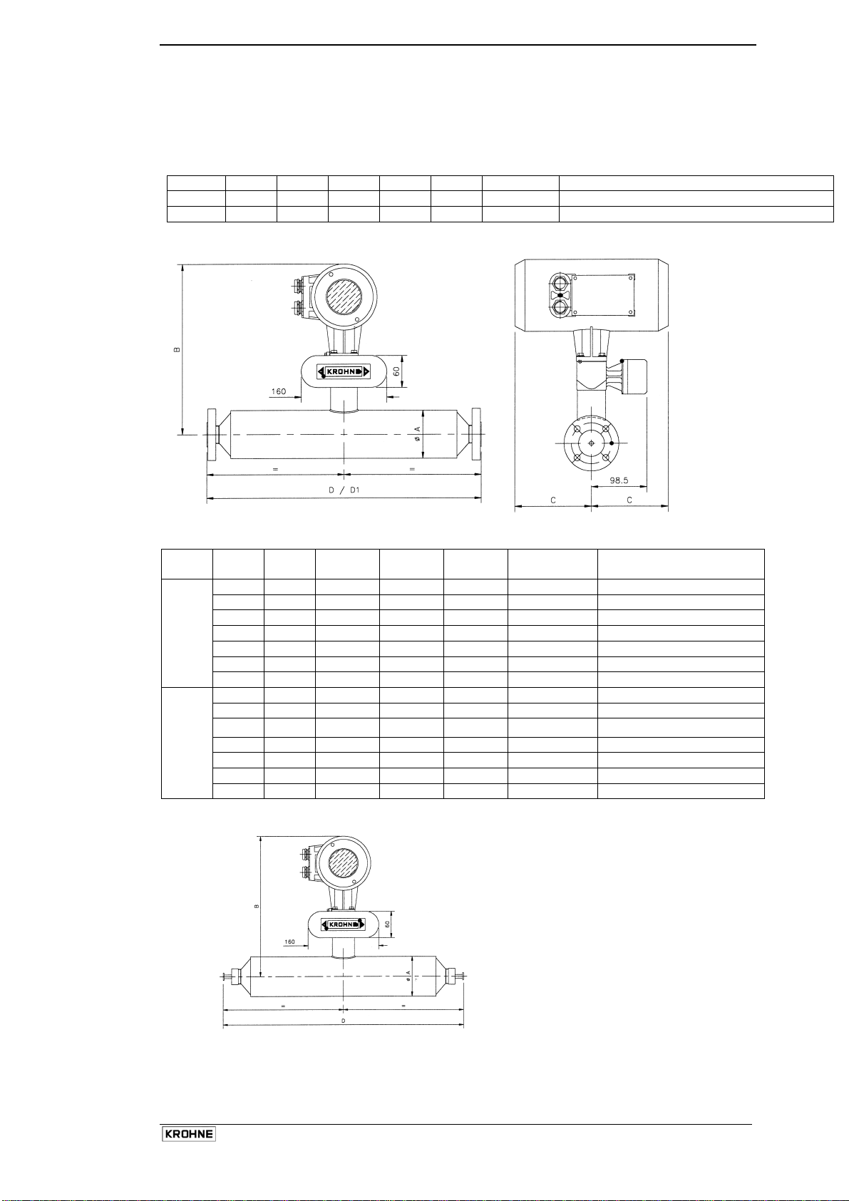
1.2.10 Weights & Dimensions
Weights
Weight of OPTIMASS 7000 sensor fitted with a typical standard flange in kg (lbs)
Size 06 10 15 25 40 50 80
Kg
lbs
16 20 23 35 80 145 260
35 44 51 77 176 319 572
Flanged versions
Dimensions
Meter
ø A B C std C Ex D for std
Size
mm
06 102 312 104 120 420±2 428±2
10 102 312 104 120 510±2 518±2
15 102 312 104 120 548±2 556±2
25 115 319 104 120 700±2 708±2
40 170 346 104 120 925±2 933±2
50 220 371 104 120 1101±2 1109±2
80 274 398 104 120 1460±2 1468±2
inches
06 4.0 12.3 4.1 4.7 16.5±0.08 16.9±0.08
10 4.0 12.3 4.1 4.7 20.1±0.08 20.4±0.08
15 4.0 12.3 4.1 4.7 21.6±0.08 21.9±0.08
25 4.5 12.6 4.1 4.7 27.6±0.08 27.9±0.08
40 6.7 13.6 4.1 4.7 36.4±0.08 36.7±0.08
50 8.7 14.6 4.1 4.7 43.3±0.08 43.7±0.08
80 10.8 15.7 4.1 4.7 57.5±0.08 57.8±0.08
Hygienic Versions
D1 for ANSI 600# flg. &
Flanges
tongue/groove
As for flanged meters except for
dimension D opposite
Installation and Operating Instructions OPTIMASS
20
Page 22

Meter connection size Connection type Connection standard D in mm D in inches
10
15
25
40
50
DN10 all welded din 32676 484 19.1 6
1/2" all welded tri-clover 480 18.9
DN10 all welded DIN 11864 528 20.8
DN10 all welded DIN 32676 564 22.2
1/2" all welded Tri-clover 558 22.0
DN10 adaptor DIN 11851 596 23.5
DN10 adaptor DIN 32676 590 23.2
1/2" adaptor Tri-clover 597 23.5
10A adaptor IDF Clamp 607 23.9
DN15 all welded DIN 11864 566 22.3
DN15 all welded DIN 32676 602 23.7
3/4" all welded Tri-clover 596 23.5
DN15 adaptor DIN 11851 634 25.0
DN15 adaptor DIN 32676 628 24.7
3/4" adaptor Tri-clover 635 25.0
15A adaptor IDF Clamp 626 24.6
1" adaptor SMS 652 25.7
1" adaptor IDF/ISS 664 26.1
1" adaptor ISO 2852 665 26.2
1" adaptor RJT 676 26.6
DN25 all welded DIN 11864 718 28.3
DN25 all welded DIN 32676 761 30.0
1.5" all welded Tri-clover 816 32.1
1.5" all welded ISO 2852 816 32.1
DN25 adaptor DIN 11851 802 31.6
DN25 adaptor DIN 32676 787 31.0
1.5" adaptor Tri-clover 855 33.7
1.5" adaptor ISO 2852 855 33.7
1.5" adaptor SMS 852 33.5
1.5" adaptor IDF/ISS 854 33.6
1.5" adaptor RJT 866 34.1
DN40 all welded DIN 11864 948 37.3
DN40 all welded DIN 32676 986 38.8
2" all welded Tri-clover 1043 41.1
2" all welded ISO 2852 1043 41.1
DN40 adaptor DIN 11851 1040 40.9
DN40 adaptor DIN 32676 1017 40.0
2" adaptor Tri-clover 1077 42.4
2" adaptor ISO 2852 1077 42.4
2" adaptor SMS 1074 42.3
2" adaptor IDF/ISS 1076 42.4
2" adaptor RJT 1088 42.8
DN50 all welded DIN 11864 1124 44.3
DN50 all welded DIN 32676 1168 46.0
3" all welded Tri-clover 1305 51.4
3" all welded ISO 2852 1305 51.4
DN50 adaptor DIN 11851 1220 48.0
DN50 adaptor DIN 32676 1193 47.0
3" adaptor Tri-clover 1355 53.3
3" adaptor ISO 2852 1355 53.3
3" adaptor SMS 1360 53.5
3" adaptor IDF/ISS 1354 53.3
3" adaptor RJT 1366 53.8
DN80 all welded DIN 11864 1538 60.6 80
DN80 all welded DIN 32676 1584 62.4
3" all welded Tri-clover 1527 60.1
3" all welded ISO 2852 1527 60.1
DN80 adaptor DIN 11851 1658 65.3
Installation and Operating Instructions OPTIMASS
21
Page 23
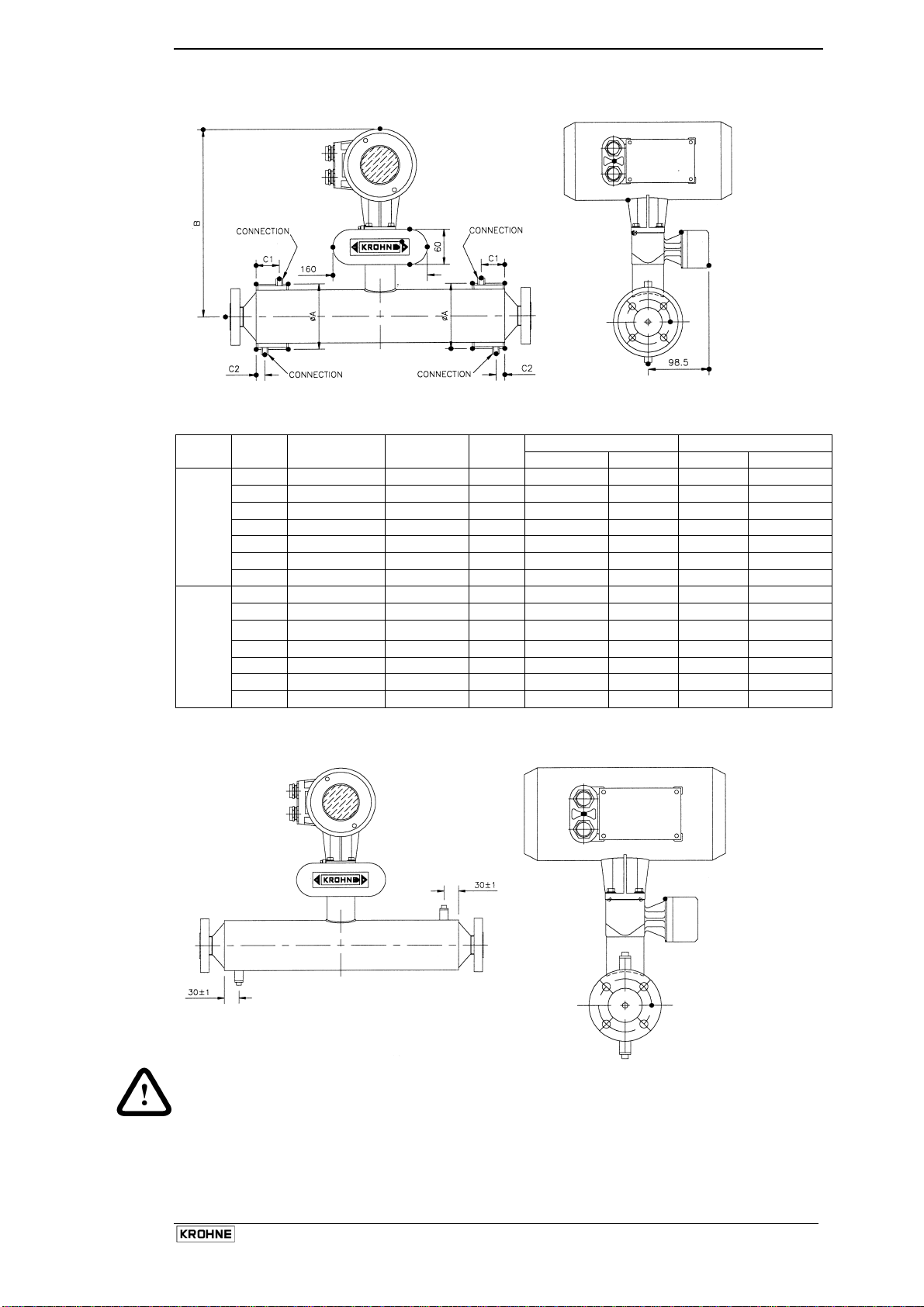
Heating Jacket
Dimensions
HJ Meter
Size
mm
10 1/2"(12 mm) 115±1 312 36±1 20
Connection
Size
15 1/2"(12 mm) 115±1 312 51±1 20 51±1 20
25 1/2"(12 mm) 142±1 319 100±1 20 55±1 20
40 1/2"(12 mm) 206±1 346 130±1 20 130±1 20
50 1/2"(12 mm) 254±1 371 180±1 20 105±1 20
50 1"(25 mm) 254±1 371 175±2 26±1 100±2 26±1
80 1"(25 mm) 305±1 398 385±2 26±1 200±2 26±1
inches
10 1/2"(12 mm) 4.5±0.04 12.3 1.4±0.04 0.8 0.8
15 1/2"(12 mm) 4.5±0.04 12.3 2.0±0.04 0.8 2.0±0.04 0.8
25 1/2"(12 mm) 5.6±0.04 12.6 3.9±0.04 0.8 2.2±0.04 0.8
40 1/2"(12 mm) 8.1±0.04 13.6 5.1±0.04 0.8 5.1±0.04 0.8
50 1/2"(12 mm) 10.0±0.04 14.6 7.1±0.04 0.8 4.1±0.04 0.8
50 1"(25 mm 10.0±0.04 14.6 6.9±0.08 1.0±0.04 3.9±0.08 1.0±0.04
80 1"(25 mm 12.0±0.04 15.7 15.2±0.08 1.0±0.04 7.9±0.08 1.0±0.04
Purge Ports (optional)
ø A B
Titanium Hastelloy
C 1 C2 C 1 C2
Note: For all other dimensions see compact version
Installation and Operating Instructions OPTIMASS
22
Page 24

1.3 OPTIMASS 3000 (7100) Single Z Shaped Tube Meter
1.3.1 Specific Installation Guidelines
When installing, please observe the following:
• Four holes are provided in the base plate and all four should always be used.
• The plastic inserts in the base plate mounting holes are important to ensure a rigid and stable
connection to the mounting structure.
• It is important to mount on a firm and rigid structure to obtain a stable zero condition.
• The following guidelines are provided to assist the installer to select the best option:
Flow
Vertical mount is possible. Horizontal mount is possible.
.
Flow
Take care to avoid gas build up in top half of tube
bends.
Do not suspend from flanges alone. Base must
always be supported.
Do not install upside down
Installation and Operating Instructions OPTIMASS
23
Page 25

Flanged and Tri-clamp Meters
When installing these meters ensure that the pipework is supported behind the process flange, so that no
unnecessary stress is applied to the meter flanges.
1.First fix meter to firm support
2.Carefully align process flanges
and connect
3.Support process pipe close to
flanges – do not pull pipe with
clamps
4. Make final process
connections – if no connections
in this area, try to have some
flexibility in process pipe
Note :
Please note that gas bubbles can also accumulate between flange and measuring tube due to the step
change, mount vertically to avoid this.
1.3.2 Ambient / Process temperatures
The specified and approved ambient and process temperatures must be observed.
SS316L or HC22
°C °F
Process -40 .. +150 -40 .. +300
Ambient
Compact -40 .. +55 -40 .. +130
Remote -40 .. +60 -40 .. +140
Note:
Where meters are mounted in direct sunlight, it is recommended to install a sunshade. This is particularly
important in countries with high ambient temperatures.
1.3.3 Pressure Equipment Directive (PED) requirements.
To comply with the requirements of the PED in Europe, the following information is provided to assist the
plant engineer in installing the meter.
Measuring tube: S Stainless SS 316 L
H Hastelloy C22
The outer cylinder (Secondary Pressure containment) 304 / 304L is dual certified and with “0” rings in pairs
of Viton and hydrogenated nitrile. (Optional outer cylinder of 316/316L).
Wiring feedthrough is made of Epoxy.
Flanges all 316 / 316 L dual certified.
Optional heating jacket 316 / 316L.
Note :
Outer cylinder is in contact with heating medium.
Installation and Operating Instructions OPTIMASS
24
Page 26
1.3.4 Secondary Pressure containment
The OPTIMASS 3000 (7100) meters are supplied with secondary pressure containment as standard.
Allowable maximum secondary containment pressures are 30 bar at 20°C or 435 psig at 70°F, and is derated as follows :
20 °C 50°C 100°C 150°C
30 bar 28.5 bar 26.1 bar 24 bar
The de-rating is based on the reduction of material strength with temperature for 316L (W No. 1.4404)
material from DIN 17456.
Heating jacket is rated to 10 bar at 150°C or 145 psig at 300°F.
If heating jacket fitted, secondary containment is limited to 10 bar at 150°C or 145 psig at 300°F. This is
because the jacket is fitted inside of the secondary containment dome.
If meter operating pressure is higher than the secondary containment allowable pressure then a relief or
bursting disk option (fitted in the dome) MUST be ordered. In this case the meter data plate is stamped
with maximum pressure rating (at maximum operating temperature) of the connection or the primary tube
(whichever is the lower).
Note:
Burst disc options are not available in combination with a heating jacket.
1.3.5 Pressure de-rating
Meter data plates are stamped with maximum pressure rating (at max. operating temperature) of
connection, primary tube or secondary pressure containment (whichever is the lower). Higher pressures
may be possible at lower temperatures.
Stainless Steel tubes: 150 bar at 80°C or 2175 psi at 175°F
50 bar at 150°C or 725 psi at 300°F
Hastelloy C22 tubes: 150 bar at 150°C or 2175 psi at 300°F
(no de-rating required)
Pressure Derating
Pressure/temperature de-rating for SS and Hast C22
all process connections except hygienic
160
140
120
100
80
Pressure in bar
60
40
20
0
-50 -30 -10 10 30 50 70 90 110 130 150
Note:
All operating p ressures abov e the
secondary pressure cont ainment
pressure will have a bursting disk fitted
to the secondary containment dom e.
Temperature in deg.C
316 SS tube
Hast C22 tube
30 bar pressure
containment
Installation and Operating Instructions OPTIMASS
25
Page 27

1.3.6 Heating and insulation
All secondary containment and heated jacket parts are 316L, except the 1/4" NPT Female connections,
which are 316.
Max heating medium pressure and temperature is 10 bar at 150°C or 145 psig at 300°F.
The max secondary containment pressure on the OPTIMASS 3000 (7100) when fitted with a heating
jacket is 10 bar at 150°C or 145 psig at 300°F.
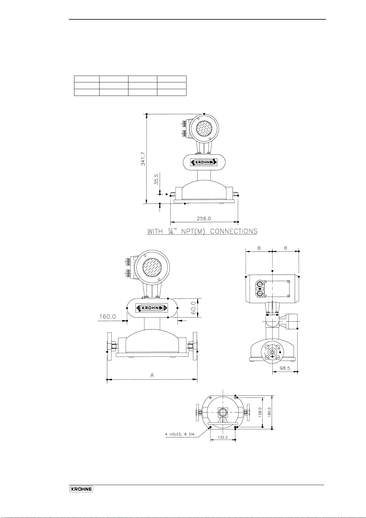
WITH ¼”NPT(M) INLET/OUTLET
WITH ¼”NPT(M) INLET/OUTLET
CONNECTIONS
CONNECTIONS
¼” NPT (F) HEATED
¼” NPF (F) HEATED
JACKET CONNECTION
JACKET CONNECTION
1.3.7 Purge Port Meters and Burst Disk Meters
Purge Port Options
If the purge port option was selected at time of order, then your meter will be fitted with 1/4" NPT female
connections – these will be clearly identified. These connections are sealed with NPT plugs and PTFE
tape.
Important:
Do not remove these plugs.
The meter is factory sealed with a dry nitrogen gas fill and any ingress of moisture will damage the
meter. The plugs should only be removed to purge the inside of the meter case of any product if it is
suspected that the primary measuring tube has failed. This must only be done after the meter has been
depressurised and removed from service. This should be done as soon as possible after failure is
suspected (less than 3 days)
Burst Disk meters
OPTIMASS 3000 (7100) meters that have been ordered with a bursting (rupture) disk will be so fitted.
This is fitted when the operating pressure of the measuring tube exceeds the design pressure of the
secondary containment. The disk failure pressure is 20bar @ 20°C.
Important:
The burst disk is suitable for the designed application according to the process conditions and flow rates
as per original order. If conditions alter, consult KROHNE for further advice regarding suitability of disk
fitted.
If the product is in any way hazardous, it is strongly recommended that an exhaust tube is connected to
the NPT male thread of the burst disk so that the discharge can be piped to a safe area. This tube
should be large enough that pressure cannot build up in the meter case.
Ensure arrow on burst disk is pointing away from meter.
Installation and Operating Instructions OPTIMASS
26
Page 28

1.3.8 Technical Data
Nominal Flow Rates
01 03 04
Kg/h
Lbs/min
15 100 350
0.5 3.5 12.5
Maximum flow rate
Typically 130 % of the nominal flow rate for the sensor size depending on application.
Minimum flow rate
Depending on measuring error required.
Tube materials:
• S 316L
• Hastelloy C22
The meter size has a prefix S or H indicating the tube material.
Secondary pressure containment
• All OPTIMASS 3000 (7100) Series meters have secondary containment rated to 30 bar or 435 psi.
Materials of construction
• Connections: SS 316 L or HC22
• Secondary Containment: SS 316 L
• Front end housing and post: SS 316 L
• Converter housing: Epoxy coated aluminium
Installation and Operating Instructions OPTIMASS
27
Page 29
1.3.9 Weights & Dimensions
Weights
Weight of OPTIMASS 3000 (7100) sensor fitted with a typical standard connection in kg (lbs)
Size 01 03 04
Kg
lbs
12 12 12
26.4 26.4 26.4
Standard Connections
Flanged and Hygienic Connections
Installation and Operating Instructions OPTIMASS
28
Page 30
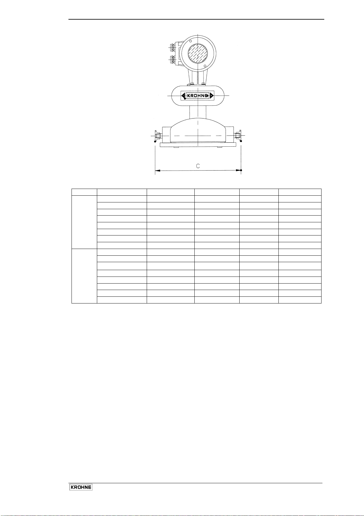
Dimensions
7100 Flange Size ø A B std B Ex C
mm
None 256 104 120 N/A
ANSI 150 286±2 104 120 N/A
ANSI 300 286±2 104 120 N/A
ANSI 600 295±2 104 120 N/A
DIN15 PN40 286±2 104 120 N/A
DIN15 PN63 295±2 104 120 N/A
DIN10 DIN 32676 N/A 104 120 260
1/2" TRI CLOVER N/A 104 120 261.6
inches
None 10.1 4.1 4.7 N/A
ANSI 150 11.3 4.1 4.7 N/A
ANSI 300 11.3 4.1 4.7 N/A
ANSI 600 11.6 4.1 4.7 N/A
DIN15 PN40 11.3 4.1 4.7 N/A
DIN15 PN63 11.6 4.1 4.7 N/A
DIN10 DIN 32676 N/A 4.1 4.7 10.2
1/2" TRI CLOVER N/A 4.1 4.7 10.3
Installation and Operating Instructions OPTIMASS
29
Page 31

1.4 OPTIMASS 8000 / 9000 Meter with Twin U Measuring Tubes
1.4.1 Specific Installation Guidelines
• Tighten flange bolts evenly.
• Do not stress the sensor mechanically. Clamp and support the connecting pipework accordingly.
• It is permissible to support the weight of the meter on the square body.
• Cavitation and Mechanical vibration should be avoided.
• Use of standard pipework reducers at the flange is allowed. Avoid extreme changes in pipe size
(step changes).
• The use of flexible hoses directly at the meter is not permitted.
• Installation below 0°C - mount vertically, or horizontally with converter up to prevent freezing or
condensation in housing.
Horizontal Mounting:
Liquids
1.4.2 Ambient / Process temperatures
The specified and approved ambient and process temperatures must be observed.
8000 9000
°C °F °C °F
Process
Safe Area -180 .. +230 -292 .. +446
ATEX/FM/CSA Compact
ATEX/FM/CSA Remote
Ambient
Compact -40 .. +55 -40 .. +130 - Remote -40 .. +60 -40 .. +140 -40 .. +60 -40 .. +140
Note:
Where meters are mounted in direct sunlight, it is recommended to install a sunshade. This is
particularly important in countries with high ambient temperatures.
The maximum differential temperature between the process and ambient temperature without insulation
is 80°C or 176°F.
1.4.3 Pressure Equipment Directive (PED) requirements.
To comply with the requirements of the PED in Europe, the following information is provided to assist the
plant engineer in installing the meter.
Measuring tube: Stainless SS 316L Sealing Faces: Stainless SS 316L
Hastelloy C22 Hastelloy C22
Flanges: SS316L
Casing: Stainless Steel 316
Typical burst pressure of case is in excess of 50 bar @ 20°C
Not PED approved
Insulation is strongly recommended above 100°C
For insulated meters without heating jackets, repeated heating or cooling at rates > 30°C per hour
should be avoided to increase operational lifespan of meter.
Gasses
-40 .. +190 -40 .. +374
-40 .. +230 -40 .. +446
For liquids, measuring tube downwards so that
no gas collects in tube if no-flow.
For gasses, measuring tube upwards, so no
liquids can collect if no-flow.
0 .. +350 0 .. 662
Installation and Operating Instructions OPTIMASS
30
Page 32

1.4.4 Secondary Pressure containment
The OPTIMASS 8000/9000 series sensors do not have certified secondary containment.
If the user suspects that the primary tube has failed, the unit must be depressurised and removed from
service as soon as possible.
1.4.5 Pressure de-rating
Meter data plates are stamped with maximum pressure rating (at max. operating temperature) of
connection, primary tube or secondary pressure containment (whichever is the lower). Higher pressures
may be possible at lower temperatures.
Measuring Tubes:
Process Temperature Process Temperature Process Temperature
Maximum 150 ºC / 300 ºF Maximum 230 ºC / 440 ºF Maximum 350 ºC / 660 ºF
(9000 series only)
Meter
size
15
25
40
80
100
barg
psig
210
3045
165
2390
140
2030
125
1810
85
1230
barg
psig
185
2680
145
2100
120
1740
110
1595
75
1085
barg
psig
160
2320
125
1810
105
1520
95
1375
65
940
Flanges:
DIN flanges to EN1092-1. Note also pressure / temperature limits for measuring tubes above.
120
100
80
60
Pressure (bar)
40
20
0
-200 -150 -100 -50 0 50 100 150 200 250 300 350 400
Temperature ('C)
Flange EN1092-1 PN40
Flange EN1092-1 PN63
Flange EN1092-1 PN100
Installation and Operating Instructions OPTIMASS
31
Page 33

ANSI flanges to ASME B16.5. Note also pressure / temperature limits for measuring tubes above.
3500
3000
2500
2000
1500
Pressure (psi)
1000
500
0
-300 -200 -100 0 100 200 300 400 500 600 700
Temperature ('F)
Flange ASME B16.5 Class 150
Flange ASME B16.5 Class 300
Flange ASME B16.5 Class 600
Flange ASME B16.5 Class 900
Flange ASME B16.5 Class 1500
JIS flanges to 2220 B. Note also pressure / temperature limits for measuring tubes above.
50
45
40
35
30
25
20
Pressure ( b ar)
15
10
5
0
-200 -150 -100 -50 0 50 100 150 200 250 300 350 400
Temp erat u re ( ' C)
Flange JIS B 2220 10K
Flange JIS B 2220 20K
Hygienic and sanitary connections (all sizes)
Maximum pressure: 10 barg at 150°C or 145 psig at 302°F
Maximum pipe work forces
Forces exerted on the meter from the process pipe are not permitted. Mechanical installation should be
designed to prevent such forces.
Installation and Operating Instructions OPTIMASS
32
Page 34

1.4.6 Hygienic Applications
The OPTIMASS 8000/9000 series is available with a variety of hygienic process connectors.
When using / installing meters with hygienic process connectors, care should be taken to ensure the
meter is well supported / clamped, as the meters are heavy and could injure when disconnected from
the adjacent pipe work.
The recommended method of installation is to mount the meter against a support / wall with the body of
the meter supported / clamped. The process pipe work can then be supported off the meter.
The meter is too heavy to be supported from the thin walled piping usually associated with the hygienic
industry.
Support here
Meter supported from its body
Installation lengths
For installation lengths, please see section 1.4.10
Please check with KROHNE if you are unsure of the installation length. Many meters are built to
customer requirements / specifications especially where special hygienic process connectors have been
adapted to the meter. As these are normally non-standard, the installation length will not be given in the
technical data.
It is also recommended that the seals be replaced regularly to maintain the hygienic integrity of the
connection.
Hygienic Connection Materials
Material: SS 316L
Unless specifically requested, internal surfaces are not polished and no warranty is made as to the
surface finish. If option of EHEDG, ASME Bio-Processing or 3A approvals was selected at time of order,
all product contact surfaces are polished 0.8 micrometer Ra (Ra 32) finish or better. Only available for
hygienic connections.
Installation and Operating Instructions OPTIMASS
33
Page 35

1.4.7 Heating and insulation
Insulation
OPTIMASS 8000
Where insulation is required a variety of materials may be used to insulate the meter. Care must be taken
not to insulate the meter above the halfway mark of the electronics support post as shown in the sketch.
Do not insulate above
this line.
Strongly recommended >
100°C
Above 150°C,
recommended to use
factory supplied option.
For insulated meters without heating jackets, repeated heating or cooling at rates > 30°C per hour should
be avoided to increase operational lifespan of meter
OPTIMASS 9000 - The OPTIMASS 9000 will always be supplied with factory fitted insulation or heating
option
Electrical Heating
Electrical tape heating may be used. Do not heat above line as shown above.
Max heating temperature is 230°C or 446°F for OPTIMASS 8000 and 350°C or 662°F for OPTIMASS
9000.
Observe Ex limits.
Liquid / Steam heating jacket
The meter can be supplied with a heating jacket.
This jacket is designed to minimise the differential stress
across the meter where differences in temperature between
outer cylinder and measuring tube exist.
The connections to the heating jacket
Process Connection
are DN15 PN40, ANSI ½” 150lbs or JIS 10K 15A
Protection is IP54. Install protective roof if necessary.
Important:
Always heat jacket to working temperature
before flowing product in measuring tube.
Heating Connection
Repeated heating or cooling at rates > 30°C
per hour should be avoided to increase operational
lifespan of meter.
Optional Drain/Vent
Note :
Max heating medium temperature is 230°C or 446°F for OPTIMASS 8000 and 350°C or 662°F for
OPTIMASS 9000. Observe Ex limits also. Maximum heating medium pressure limited by jacket
connections. Refer to de-rating curves as per section 1.4.5.
Installation and Operating Instructions OPTIMASS
34
Page 36

1.4.8 Purge Port Meters and Burst Disk Meters
Purge Port Options
If the purge port option was selected at time of order, then your meter will be fitted with 1/4" NPT female
connections – these will be clearly identified. These connections are sealed with NPT plugs and PTFE tape.
Important:
Do not remove these plugs.
The meter is factory sealed with a dry nitrogen gas fill and any ingress of moisture will damage the meter.
The plugs should only be removed to purge the inside of the meter case of any product if it is suspected that
the primary measuring tube has failed. This must only be done after the meter has been depressurised and
removed from service. This should be done as soon as possible after failure is suspected (less than 3 days)
Burst Disk meters
OPTIMASS 8000/9000 meters that have been ordered with a bursting (rupture) disk will be so fitted. This is
fitted when the operating pressure of the measuring tube exceeds the design pressure of the secondary
containment. The disk failure pressure is 20bar @ 20°C.
Important:
The burst disk is suitable for the designed application according to the process conditions and flow rates as
per original order. If conditions alter, consult KROHNE for further advice regarding suitability of disk fitted.
If the product is in any way hazardous, it is strongly recommended that an exhaust tube is connected to the
3/4" NPT male thread of the burst disk so that the discharge can be piped to a safe area. This tube should
be large enough that pressure cannot build up in the meter case.
Ensure arrow on burst disk is pointing away from meter.
1.4.9 Technical Data
Nominal Flow Rates
15 25 40 80 100
Kg/h
Lbs/min
2,700 9,000 32,000 85,000 250,000
100 300 1,200 3,000 9,300
Maximum flow rate
Typically 130 % of the nominal flow rate for the sensor size depending on application.
Minimum flow rate
Depending on measuring error required.
Materials of construction
Measuring Tubes SS 316L or HC-22
Flanges SS 316L or
SS316L backing with HC-22 raised face
Outer Casing SS 304
Converter Mount & Front End electronics SS 316L
1.4.10 Weights & Dimensions
Weights
Weight of OPTIMASS 8000/9000 sensor fitted with a typical standard flange in kg (lbs)
Model / Size
15 25 40 80 100
kg lbs kg lbs kg lbs kg lbs kg lbs
8000 Sensor 10.9 24 14.4 32 23.4 51.5 61.4 135 89.4 197
9000 Sensor with insulation
housing
14.9 32.8 20.4 44.8 30.9 68 79 174 125 275
Installation and Operating Instructions OPTIMASS
35
Page 37

Flanged & Hygienic Connections
Dimension A
EN 1092-1 MATERIAL
PN40 S/S 370 370 500 500 600 600 610 1000 1000 1100 1100
HAST - 390 500 520 - 620 620 1000 1000 - -
PN 63 S/S - - - - - 620 620 - - - -
HAST - - - - - - - - - - -
PN100 S/S 380 390 520 560 620 660 730 - - - -
HAST - - - - - - - - - - -
ANSI B16.5 MATERIAL
150 lb S/S 370 370 500 500 600 600 610 1000 1000 1100 1100
HAST - 390 500 520 - 620 620 1000 1000 - -
300 lb S/S - 370 - 510 - 600 620 - - - -
HAST - 390 - 520 - 620 620 - - - -
600lb S/S 380 390 520 560 620 630 640 - - - -
HAST - - - - - - - - - - -
900 lb S/S - - - - 640 720 760 - - - -
HAST - - - - - - - - - - -
1500lb S/S 400 450 540 600 - - - - - - -
HAST - - - - - - - - - - -
JIS B 2220 MATERIAL
10K S/S 370 370 500 500 600 600 600 1000 1000 1100 1100
20K S/S 370 370 500 500 600 600 600 1000 1000 1100 1100
SIZE 15 SIZE 25 SIZE 40 SIZE 80 SIZE 100
DN15 DN25 DN25 DN40 DN40 DN50 DN80 DN80 DN100 DN100 DN150
SIZE 15 SIZE 25 SIZE 40 SIZE 80 SIZE 100
½” 1” 1” 1.5” 1.5” 2” 3” 3” 4” 4” 6”
SIZE 15 SIZE 25 SIZE 40 SIZE 80 SIZE 100
DN15 DN25 DN25 DN40 DN40 DN50 DN80 DN80 DN100 DN100 DN150
Installation and Operating Instructions OPTIMASS
36
Page 38

Triclamp
DIN32676 & ISO2852 Material SIZE 15 SIZE 25 SIZE 40 SIZE 80
DN25 DN40 DN50 DN65 DN100
S/S 370 500 600 600 1020
Triclover Triclamp Material SIZE 15 SIZE 25 SIZE 40 SIZE 80
1" 1 1/2" 2" 3" 4"
S/S 370 500 600 600 1020
DIN 11851 Male Material SIZE 15 SIZE 25 SIZE 40 SIZE 80
DN25 DN40 DN50 DN100
S/S 380 510 600 1050
Other major external dimensions (for all process connections)
SIZE B C D E F G H J K Std K Ex
15 272 212 180 368 429 80 60 80 104 120
25 400 266 233 368 429 80 76 90 104 120
40 490 267 274 378 439 100 89 110 104 120
80 850 379 430 395 456 135 129 160 104 120
100 870 455 453 428 489 200 155 200 104 120
Installation and Operating Instructions OPTIMASS
37
Page 39

Insulated / Heated Jacket Meters
Major external dimensions of insulating and heating jacket options.
SIZE L M N P R S T
15 420 310 330 200 411 138 240
25 540 439 380 250 464 138 260
40 640 530 430 250 524 148 260
80 1000 884 580 350 684 165 304
100 1040 932 590 350 730 200 343
Installation and Operating Instructions OPTIMASS
38
Page 40

2 Electrical Installation
2.1 Location and connecting cables
Location
Do not expose the compact flow meter to direct sunlight in hot climates. Install a sunshade if necessary.
Connecting cables
To conform to protection category requirements, observe the following recommendations:
• Fit blanking plug and apply sealant to unused cable entries.
• Do not kink cables directly at cable entries.
• Provide water drip point (U bend in cable).
• Do not connect rigid conduit to cable entries.
• Only cables of diameter 7 to 12 mm or ¼” to ½” can be used.
2.2 Connection to power
Please ensure that the information about power given on the data plate corresponds to the locally
available mains voltage.
• Note information given on the instrument data plate (voltage, frequency)!
• Electrical connection in conformity with IEC 364 or equivalent national standard. Special regulations
apply to installation in hazardous areas. (See supplementary installation and operating instructions)
• The PE protective ground conductor must be connected to the separate U-clamp terminal in the
terminal box of the signal converter.
• Do not cross or loop the cables in the terminal box of the signal converter. Use separate cable glands
for power and output cables.
• Ensure that the screw thread of the round cover on the terminal box is well greased at all times.
Note:
• The grease used must be non-corrosive to aluminium; typically it must be resin- and acid-free.
• Protect sealing ring from damage.
2.2.1 Power Supply Wiring MFC050
Outputs and
connections
Power and signal connections for MFC 050
2.2.2 Power Supply Wiring MFC051 Non Ex
24 V AC/DC 100 – 230 V AC mains
PE
24 V AC/DC
Outputs
Installation and Operating Instructions OPTIMASS
N L AC
– + DC
PE
L N
PE
39
Page 41

2.2.3 Power Supply Wiring MFC 051 Ex
Slide the cover to the left to expose the power terminals. Power supply terminals covered.
Terminal designation as per section 2.2.2.
2.3 Connection of remote meters
The OPTIMASS meter can be supplied as a remote meter with up to 300 m or 1000 ft distance between
sensor and converter.
Connect cable marked A, B, +, - to corresponding terminals in remote junction box as per sketch below.
A
Remote 4
core cable
connectors
B
+
-
Installation and Operating Instructions OPTIMASS
Remote 4 core
Cable Connectors
40
Page 42

Shield is connected through the cable gland.
Hazardous Area requirements
2.4
• Hazardous Area Installation.
• For further information please see supplementary installation and operating instructions.
• Please follow these guidelines explicitly for mechanical and electrical connections.
• General cabling guidelines.
To maintain the IP 67 / NEMA 4x protection it is necessary to ensure that the correct size cable is used for
the cable glands. Please ensure that the cable glands are well tightened. Provide a “drop” loop for water
to drip off.
2.5 Inputs and outputs
2.5.1 Inputs/Outputs MFC 050
The MFC 050 has many options and variations for the inputs/outputs.
The meter is shipped from the factory with one of the following options pre-configured:
Option Function
1 1 x current,1 x pulse,1 control input,1 x status output-HART
2 1 x current plus Modbus
3 Dual phase frequency output, 1 x current, 1 x control input - HART
4 2 x current, 1 x pulse, 1 x control input, HART
5 2 x current, 1 control input,1 x status output-HART
6 3 x current, 1 x pulse - HART
7 3 x current, 1 x control input - HART
8 3 x current, 1 x status output - HART
If you are not sure what option is fitted to the converter, this may be viewed at program Fct. 4.1 IO
FITTED.
On the MFC050, the inputs/outputs have a common signal ground that is galvanically isolated from the
Potential Earth (PE).
Note
HART® is available on the first current output except for option 2, where a communication option is already
available.
Installation and Operating Instructions OPTIMASS
41
Page 43

Output Option 1
Active status O/P 24V DC
Pulse O/P (Passive)
Input < 24V DC
4-20 mA
Common
Active Status Output
The status output can be programmed to provide a constant 24V (20mA maximum) which can be used as
the power source for the pulse output and control input.
Set Menu 4.6.1 to OFF
Set Menu 4.6.2 to ACTIVE LOW
Example Circuits
Load < 500Ω
V < 24 V DC
R >
V
0.15
Pulse
0V DC
Fig 1 : 1 x current output Fig 2 : Pulse output external power
> I500Ω
Pulse
0V DC
Status 24V,
<20mA
0V DC
Fig 3 : Pulse output status powered Fig 4 : Active status output
Installation and Operating Instructions OPTIMASS
42
Page 44

Contact
Input
<24V DC
Fig 5 : Binary input
Fig 6 : Binary input status powered
0V DC
> I500Ω
< 24V DC
Contact
Contact
Pull down IKΩ
0V DC
Fig 7 : Binary input status powered
Fig 8 : Binary input external powered
< 24V DC
Output
ETC.
Relay Relay
Fig 9 : Pulse relay status powered ; 24v DC <20mA relay
Fig 10 : Pulse relay, external powered ;
24VDC <150mA
Output
ETC.
Output
ETC.
Relay
Fig 11 : Active status relay ; 24V DC <20mA relay
Installation and Operating Instructions OPTIMASS
43
Page 45

Output Option 2
Modbus
Current Output
Refer to communications handbook for details of Modbus connections
Output Option 3
A
B
B LAGS A BY 90°
Common 0 V
Pulse 2
Pulse 1
Common 0 V
Phase shifted pulse (Passive) for Custody Transfer
Alternative to drive 2 pulse outputs.
applications
Note:
It is not possible to provide two independently assignable and scaleable frequency outputs for two
separate measurements.
Pulse output is passive. Refer to Figs. 2 & 10 for circuit examples.
Output Option 4
Pulse Output (Passive)
Control Input (Passive)
Current Output 2
Current Output 1
Common 0 V
Installation and Operating Instructions OPTIMASS
44
Page 46

Output Option 5
Status Output (Passive)
Control Input (Passive)
Current Output 2
Current Output 1
Common 0 V
V < 24 V DC
> IK5R
Status
Common 0V
Rela
y
<24 V DC
Output
ETC.
Common 0V
Passive Status Output Passive Status Relay ; 24VDC < 20mA relay
Output Option 6
Output Option 7
Pulse Output (Passive)
Current Output 3
Current Output 2
Current Output 1
Common 0 V
Control Input (Passive)
Current Output 3
Current Output 2
Current Output 1
Common 0 V
Output Option 8
Status Output (Passive)
Current Output 3
Current Output 2
Current Output 1
Common 0 V
Installation and Operating Instructions OPTIMASS
45
Page 47

2.5.2 Inputs / Outputs MFC051
The MFC 051 offers galvanically separated outputs in the non-hazardous area version and intrinsically
safe outputs for the Hazardous area approved version (see Supplementary Installation and Operating
Instructions).
All outputs are passive.
The converter is shipped from the factory with the required output option fitted and configured. These
cannot be changed in the field as the modules are soldered in place. The black covers over the modules
are necessary to prevent spurious signals as the galvanic separation is done optically.
To view the actual outputs fitted, go to Fct. 4.1 I/O FITTED. The connection will also be indicated on an
adhesive label in the lid of the terminal compartment.
Option Function
1 2 x 4-20 mA-HART (outputs galvanically separated from each other)
2 1 x 4-20 mA, 1 X Pulse-HART
3 1 x 4-20 mA, 1 x Control input-HART
4 1 x 4-20 mA, 1 x Status output-HART
5 1 X 4-20 mA, 1 X Profibus PA
Note
HART® is available on the first 4...20 mA output except for option 5, where Profibus is available.
As the outputs are passive, HART® can be used in a multi-drop loop or as a point-to-point communication.
Output Option 1
250 R
250 R
Passive current output
Output Option 2
In addition to the 1
5 … 30 V DC
18 … 30 V DC
0 V DC
18 … 30 V DC
0 V DC
st
4...20mA, a passive pulse output can be wired as shown.
300 R
Pulse
0 V DC
Installation and Operating Instructions OPTIMASS
46
Page 48

Output Option 3
In addition to the 1
st
4...20mA, a control or binary input can be wired as shown.
5 … 30 V DC
Contact
0 V DC
Output Option 4
In addition to the 1
st
4...20 mA, a status or alarm output can be wired as shown.
300 R
Status
0 V DC
5 … 30 V DC
Output Option 5
The Profibus communication output available on this converter can be wired as shown in addition to a
4...20mA output. Refer to communication handbook for connection details
Profibus PA
Installation and Operating Instructions OPTIMASS
47
Page 49

2.6 Compact to Remote / Remote to Compact conversion instructions
Conversion of the mounting of the signal converter from compact to remote, or vice-versa, is possible
under certain circumstances, using a kit of parts.
A change from compact to remote or vice versa in the field is possible in safe areas, for hazardous areas
only in the workshop.
Contact your local KROHNE Company and provide the serial number of the meter for further details.
2.7 Technical Data
2.7.1 MFC050
Power Supply
Operating Voltage : 115V AC (+10% / -15%)
230V AC (+10% / -15%)
24V DC (+/- 30%)
Power consumption : AC – 18VA
DC – 10W
Inputs and Outputs
Current (mA) output
Function : Active (converter powered)
Level : 0/4 … 20mA
Maximum Load :
Pulse Output
Function : Passive (externally powered) open collector transistor switch
Maximum Frequency : Frequency – 1300Hz, Pulse – 10 KHz
Pulse width : 0.05 … 500 mS (settable)
External power supply : <24V DC
Maximum circuit current : < 150mA
Control Input
Function : Passive (externally powered)
Input signal state high : 4 … 24V DC
Input signal state low : < 2V DC or open circuit
Status Output
Function : Active (converter powered) or
Active configuration Output signal state high : 24V DC
Output maximum current : 20mA
Passive configuration External circuit voltage : < 24V DC
Maximum circuit current : 20mA
500Ω
Passive (externally powered) depending on output options fitted
Installation and Operating Instructions OPTIMASS
48
Page 50

2.7.2 MFC051
Power Supply
Operating Voltage : 100 – 230V AC (+10% / -15%)
24V DC (+/- 30%)
Power consumption : AC – 18VA
DC – 10W
Inputs and Outputs
Current (mA) output
Function : Passive (externally powered)
Level : 4 … 20mA
External Power supply : 8 … 30V DC
Pulse Output
Function : Passive (externally powered) open collector transistor switch
Maximum Frequency : Frequency – 1300Hz, Pulse – 10 KHz
Pulse width : 0.05 … 500 mS (settable)
External power supply : 6 … 30V DC
Maximum circuit current : < 110mA
Control Input
Function : Passive (externally powered)
Input signal state high : 7 … 30V DC
Input signal state low : < 2V DC or open circuit
Maximum circuit current : < 110mA
Status Output
Function : Passive (externally powered)
External circuit voltage : < 6 … 30V DC
Maximum circuit current : < 110mA
Profibus PA
Hardware : According to IEC 61158-2 and FISCO model
External circuit voltage : 9 … 30V DC
Maximum circuit current : < 300mA
Installation and Operating Instructions OPTIMASS
49
Page 51

3 Start-Up
3.1 Factory Set Parameters
The mass flow meter leaves the factory ready to be used. All process data has been programmed
according to the customer order.
When no process details were supplied at the time of order, the mass flow meter is programmed to a
standard default set of values and functions.
The current and pulse outputs treat all flows as positive. The actual flow and quantity is thereby
measured independent of the flow direction. The indicator will indicate a ” – ” or ” + ” in front of the flow
rate.
These factory-set settings for current and pulse may cause an error under the following conditions:
When the pump is stopped and a reverse flow is present, which is larger than the low flow cut-off or
when totalising should be indicated for both flow directions.
To avoid these possible problems:
• Set flow mode (Fct. 3.1.3) to either flow > 0 or Flow < 0, so that reverse flows are ignored.
or
• Increase Low Flow cut-off (Fct. 3.1.1) so that small reverse flows are ignored.
or
• Set the alarm output (Fct. 4.6.1) to DIRECTION so that external equipment can differentiate between
positive and negative flows.
3.2 Initial Start-up
• Please check that the power supply corresponds to the information supplied on the data plate.
• Switch on the power supply.
• On switch-on, the signal converter first carries out a self-test. The following sequence is displayed:
Mass flow will be displayed following a brief settling phase for the primary head.
A minimum warm-up time of 30 minutes is recommended to ensure stable measurement operation.
• For stable and accurate mass flow results the following should be checked:
a) The quality of the mechanical installation. See Sect. 1.
b) A good zero point calibration should be done. See Sect. 3.3. Further information regarding zero
point calibration can be found in Sect. 5.
* TEST
* SW.VER VX.XX
* OPTIMASS
XX5X
* START UP
Installation and Operating Instructions OPTIMASS
50
Page 52

3.3 Zero point adjustment
After installation adjust the zero point. To do this, the primary head must be completely filled with the liquid
product without gas or air inclusions. This is best obtained by allowing the liquid product to flow through
the primary head for approx. 2 minutes at a throughput rate of greater than 50% of rated flow.
Subsequently ensure that flow comes to a complete stop in the primary head (see Section 1.1) for setting
the zero without interruption to product flow, use a bypass set-up as shown in Section 1.1.
Now initiate zero adjustment by way of the following keystroke combination:
Start from measuring mode
Key Display
→
2x→
↑
↵
Line 1 Line 2
Fct. (1) OPERATION
Fct. 1.1.(1) AUTO. CALIB.
CALIB. (YES)
X.X PERCENT
ACCEPT. (YES)
↵
3x↵
↵
Fct. 1.1.(1) AUTO. CALIB.
ACCEPT. (YES)
Display
Under certain conditions, it may not be possible to adjust the zero point:
• If the medium is in motion. Shut-off valves not tightly closed.
• If there are gaseous inclusions in the primary head. Flush the primary head and repeat the calibration.
• If resonant oscillations of the piping are interfering with the primary head. If there are active warning(s)
in the status message list. (See section 6)
In such cases, the zero point adjustment procedure is automatically aborted and the following message is
displayed:
ZERO.ERROR
Press ↵ and then the converter returns to the start of the function 1.1.1:
Fct. 1.1.1 AUTO. CALIB
Further information on zero point adjustment is given in Section 4.
The OPTIMASS is ready to operate after zero has been adjusted.
All parameters have been factory-set in keeping with the data specified in your order.
Detailed information for further setting of the signal converter will be found in section 4 and 5 of the
operating instructions.
3.4 Programming the converter with a bar magnet
• The converter can be programmed by means of the magnetic sensors mounted on the faceplate
without removing the front lid.
• To do this, a bar magnet (standard supply) is used to activate the sensors by holding the magnet close
to the glass window of the housing lid.
• These sensors then duplicate the functions of the push buttons.
• This is mandatory in Ex
environments
• Also recommended in
KROHNE MFC 50
humid environments
Installation and Operating Instructions OPTIMASS
51
Page 53

4 Programming the Converter MFC 050/051
4.1 Operating and check elements
The operating elements are accessible after removing the cover of the electronics section using the
special wrench. The converter is also programmable with magnetic sensors and a bar magnet without
removing the covers of the electronic housing.
Caution:
Do not damage the screw thread and the gasket, never allow dirt to accumulate, and make sure they are
well greased at all times.
1 Display 1st (top) line
2 Display 2nd (middle) line
3 Display 3rd (bottom) line:
KROHNE MFC 50
arrows (▼) to identify the state of the signal
converter
• Status message indicator
• Standby mode
4 Keys for operator control of the signal
converter.
5 Magnetic sensors to set the converter by
means of a handheld bar magnet without
opening the housing. Function of sensors
same as keys (4).
6 Compass field, signals actuation of a key.
The operator control concept consists of five levels (horizontal). See next page.
Setting level:
This level is divided into 5 main menus:
Fct. 1.0 OPERATION: This menu contains most important functions for
adjustment and calibration.
Fct. 2.0 TEST: Test menu for checking the signal converter (displays, outputs,
measuring range) and meter diagnostics.
Fct. 3.0 CONFIG: All flow measurement- and flowmeter-specific parameters
and functions can be set in this menu.
Fct. 4.0 I.O. CONFIG:The configuration of the outputs, input, communication
and the system control can be set in this menu.
Fct. 5.0 FACTORY.SET: All meter related factory settings and meter constants
can be monitored in this menu.
Reset/acknowledge
level (Quit):
This menu has two tasks and is selected via Entry Code 2 ( ↵ ↑ → ).
• Resetting of totalizer, provided that resetting is enabled under
Fct. 3.5.3 ENABL.RESET, input YES.
• Status message and acknowledgement (Quit) messages that have occurred
since the last acknowledgement are indicated in a list.
After elimination of the cause(s) and acknowledgement, these messages
are deleted from the list.
Installation and Operating Instructions OPTIMASS
52
Page 54

4.2 OPTIMASS MFC 050/051 Operating Concept
Installation and Operating Instructions OPTIMASS
53
Page 55

4.3 Key functions
Function of the keys
Cursor The location of the cursor on the display is indicated by flashing characters. This
could be a single digit when entering number; numeric sign ( + or -) ; measurement units (g,
kg, t etc.); or any other text field. Throughout this manual the location of the cursor, in
programming examples, will be indicated by parentheses ( ) around the flashing characters.
↑
→
↵
Note:
If numerical values are set that are outside the permissible input range, the display shows the min. or max.
acceptable value. After pressing the ↵ the number may be corrected.
Select or Up Key. This key changes the field/digit under the cursor.
Digit:
Dec. pt..
Menu
Increase value by 1 for each key press. (0 follows 9).
Move decimal point. 0000(.)0000 changes to 00000(.)000
Increase menu number by 1. i.e. Fct. 1.(1).0 changes to Fct. 1.(2).0
When the menu number reaches its maximum the next ↑ changes the number
to 1. i.e. Fct 1.(3)changes to Fct 1.(1)
Text
Sign
Change text field. i.e. ”YES” to ”NO” or ”g” to ”kg” to ”t” etc.
Toggle ”+” to ”-”
Cursor or Right Key. This key moves the cursor onto the next field to be edited. (usually the
next on the right).
Number
Text
Menu
Move cursor from 12(3).50 to 123(.)50 to 123.(5)0
Move to next field. i.e. (kg)/min to kg/(min)
Move to next menu column: i.e. from Fct 1.(1) to Fct. 1.1.(1)
or
if the cursor is already in the rightmost column: invoke that menu function. i.e.
from Fct. 1.1.(1) press → to enter Zero adjustment.
Accept or Enter Key.
Within a
Accept changes (if any) and exit the function.
function
Menu
Move cursor to the next column on the left.
i.e. from Fct. 1.1.(1) back to Fct. 1.(1)
If the cursor is already in the leftmost column then ↵ exits the menus. See next
box: ”To terminate” .
Installation and Operating Instructions OPTIMASS
54
Page 56

4.3.1 How to enter programming mode
To start:
→ Press
Display Comments
Fct. 1
If this appears, see box: ”Function of the keys ” in 4.3.
OPERATION
or
CodE 1
---------
If this appears on the display, set the 9-keystroke Supervisor CodE
1 .
Factory setting: → → → ↵ ↵ ↵ ↑ ↑ ↑
1st - 8th place
(key)
CodE 1
∗∗∗∗∗∗∗∗-
Each keystroke acknowledged by " * " in display.
9th place
(key)
Fct. 1
OPERATION
If this appears, see box: ”Function of the keys ” in 4.3.
XXXXX
CODE WRONG
A wrong Supervisor CodE 1 was keyed in. Press any key and set
the correct 9-keystroke Supervisor CodE 1.*
* If correct code is not known, note number given (XXXXX) and contact KROHNE for further instructions
regarding decoding.
4.3.2 How to terminate Programming mode
To terminate:
Press ↵ 1-5
times
↵
Display Comments
Fct (1).0
OPERATION
+ 12.3
kg/min
Press ↵ 1...5 times until the cursor is under the extreme left menu
column. (Fct. 1, 2, 3, 4 or 5).
If no changes have been made to the system’s configuration return
directly to the measurement mode.
or
(ACCEPT YES)
Changes have been detected. Press ↵ to accept these changes.
or
↑
(ACCEPT NO)
Press ↵ to reject changes and return directly to measurement
mode.
or
↑
(GO BACK)
Press ↵ to return to the menus, Fct. 1.(0) to make further changes
Return to measurement mode.
Installation and Operating Instructions OPTIMASS
55
Page 57

Examples
The cursor (flashing part of display) has a grey background in the following examples:
To start programming
Measurement mode Programming mode
1 3. 5 7 1
m 3 / h r
→
F c t. 1. 0
O P E R A T I O N
Note:
When ”yes” is set under Fct. 3.5.1 SUPERVISOR, the following will appear in the display after pressing the
→ key:
CodE 1 - - - - - - - - -.
The 9-stroke entry code must now be entered.
Factory setting: → → → ↵ ↵ ↵ ↑ ↑ ↑.
Each keystroke is acknowledged by an ” * ” in the display.
To terminate programming
Press ↵ key repeatedly until one of the following menus are displayed:
Fct. 1.0 OPERATION, Fct. 2.0 TEST or Fct. 3.0 CONFIG
Press ↵ key
F c t. 3. 0
I N S T A L L.
↵
A C C E P T. Y E S
To accept the new parameters
Press ↵ to confirm.
”WAIT” will appear in the display.
The measuring mode will continue after a few seconds
with the new parameters, when no errors are detected.
New parameters not to be accepted
When the new parameters are not to be accepted, the
following keystrokes should be executed:
• Press ↑ key.
• The display will show ”ACCEPT NO”.
When the ↵ key is then pressed, the instrument will
return to the measurement mode using the old
parameters.
To review or change parameters further
• Press ↑ key twice
• The display will show ”GO BACK”.
When the ↵ key is then pressed, the instrument will
return to the programming mode
Installation and Operating Instructions OPTIMASS
56
Page 58

To change numeric values
Increase numeric value
2 1 0 . 5 0
↑
2 1 0 . 6 0
k g / m i n
k g / m i n
To move the cursor (flashing digit)
To move to the right
2 1 0 . 6 0
→
2 1 0 . 6 0
k g / m i n
k g / m i n
To move the decimal point
To move to the right
2 1
. 0 6 0
k g / m i n
→
2 1 0
. 6 0
k g / m i n
To change the text
Select next text
↑
M A S S F L O W
D E N S I T Y
To change the units
Numeric values automatically converted
Select new unit
0 . 2 1 0 6 0
↑
g / m i n
2 1 0 . 6 0
k g / m i n
Alternative time unit
2 1 0 . 6 0
→
k g / m i n
2 1 0 . 6 0
k g / m i n
To change from numeric values back to text
Alternative engineering units
2 1 0 . 6 0
→
k g / m i n
2 1 0 . 6 0
k g / m i n
Return to function display
1 0.3
↵
F c t. 1. 1.
3
S e c
T I M E C O N S T.
Installation and Operating Instructions OPTIMASS
57
Page 59

4.4 Table of programmable functions
Fct.
No
1 OPERATION Main menu 1 Operation
1.1 ZERO CALIB. Submenu 1.1 Zero adjustment
1.1.1 AUTO. CALIB. Automatic zero adjustment
1.1.2 MANUAL CAL. Input manual zero offset
1.1.3 DISP. ZERO Display of the last zero in percent of nom. flow
1.2 INST. STATE Input of the instrument state
1.3 DENSITY.CAL Submenu 1.3 Density calibration
1.3.1 DISP. PT. 1 Display of last density calibration value point 1
1.3.2 DISP. PT. 2 Display of last density calibration value point 2
1.3.3 1 POINT.CAL. Density calibration mode: 1 point calibration
1.3.4
1.3.4
1.3.5 FACTORY.SET Reset factory settings
Text Description and settings
*1) Select: SURE YES or NO
*2) If YES: Calibration (approx. 30 sec. duration)
Display: Actual flow rate as percent of the maximum rated flow for the primary
head. (Q
*3) Select: ACCEPT YES or NO
* Direct input of a zero flow offset.
Units: As selected by Fct.
Use the key ↑ to switch between three states of operation, then press ↵:
*MEASURE
*STANDBY (tube vibrating, Mass Flow set to zero)
*STOP (tube drive stopped)
* SURE (NO). Use the ↑ key to select YES, then press ↵
Use the ↑ key to select desired calibration sample from the list below:
EMPTY
*
* WATER
* TOWN WATER
2 POINT.CAL. Densit y calibrati on mode: 2 point cali brati on
CALIB. OK.
2 POINT.CAL 2nd access to menu 1.3.4:
CALIB. OK
* OTHER
st
access to menu 1.3.4:
1
* SURE (NO). Use the ↑ key to select YES, then press ↵. Use the ↑ key to select
between
* CAL.SAMPLE1
* EXIT
Press ↵ and use the ↑ key to select desired calibration sample from the list below then
press ↵
* EMPTY
* WATER
* TOWN WATER
* OTHER
Press ↵ to return to Fct. 1.3.4
* SURE (NO). Use the ↑ key to select YES, then press ↵. Use the ↑ key to select
between
* CAL.SAMPLE2
* RESTART
* EXIT
Press ↵ and use the ↑ key to select desired calibration sample from the list below then
press ↵.
* WATER
* TOWN WATER
* OTHER
Press ↵ to return to Fct. 1.3.4
Restore density calibration to factory settings
* SURE (NO). Use the ↑ key to select YES, then press ↵.
100%
)
Installation and Operating Instructions OPTIMASS
58
Page 60

Fct.
No
2 TEST Main Menu 2. Test functions
2.1 DISPLAY. Carry out display test
2.2 CUR. OUT. 1 Test current output I
2.3 CUR. OUT. 2 Test current output 2
2.4 CUR. OUT. 3 Test current output 3
2.5 PULSE OUT. Test frequency output
2.6 FREQ. OUT. Test frequency output
2.7 ALARM OUT. Test alarm output
2.8 CONTROL.INP Test control input
2.9 DIAGNOSE Submenu 2.9 Diagnose
2.9.1 TUBE TEMP. Test temperature
2.9.2 STRAIN M.T. Test strain measuring tube
2.9.3 STRAIN I.C. Test strain inner cylinder
2.9.4 TUBE FREQ. Monitor the primary head frequency
2.9.5 DRIVE.ENEGY. Monitor the primary head's drive level
2.9.6 SENSOR A
2.9.7 SENSOR B
2.9.8 COMM.ERROR
2.10 VERSIONS Submenu 2.10 Versions
2.10.1
2.10.2 BACKEND.HW Monitor the backend hardware version
2.10.3 FRONTEND.SW Monitor the frontend software version
Text Description and settings
* SURE (NO). Use the ↑ key to select YES, then press ↵ (Duration of test approx.
30 sec.). Stop test at any time with the ↵ key.
* SURE (NO). Use the ↑ key to select YES, then press ↵. Use the ↑ key to select
test signals from the list below.
0 mA 2 mA 12 mA 16 mA 20 mA 22 mA
To exit test mode, press the ↵ key at any time.
see CUR. OUT. 1 above
see CUR. OUT. 1 Fct. 2.2 above
* SURE (NO). Use the ↑ key to select YES ,then press ↵. Use the ↑ key to select desired
pulse width from the list below:
∗ 0.05 mSec ∗ 0.4 mSec ∗ 1.0 mSec
∗ 10.0 mSec ∗ 100.0 mSec ∗ 500.0 mSec
Then press ↵. The system now sends pulses of the required width. To stop the test press
↵ twice.
* SURE (NO). Use the ↑ key to select YES ,then press ↵.
* LEVEL LOW 0 volt DC level will be output from the converter.
Use the ↑ key to select test signals from the list below.
* LEVEL HIGH (+ V volts dc)
* 1 Hz * 100 Hz
* 10 Hz * 1000 Hz
* SURE (NO). Use the ↑ key to select YES, then press ↵
* LEVEL LOW. 0 Volts is output on the alarm terminal.
Press the ↑ key to switch output to:
* LEVEL HIGH . +24V dc is output on the alarm terminal.
To exit test mode, press the ↵ key at any time.
* SURE (NO). Use the ↑ key to select YES, then press ↵.
The actual input level, HI or LO, and the selected functions are displayed see Fct. 3.6.1
End test by pressing the ↵ key.
Start with the → key. The temperature in °C or °F is displayed.
Use the ↑ key to display the temperature in °F.
End the test by pressing the ↵ key.
Start with the → key. The strain resistance in Ohms is displayed. End the test by pressing
the ↵ key.
Start with the → key. The strain resistance in Ohms is displayed. End the test by pressing
the ↵ key.
Start test with the → key. End the test with the ↵ key.
Start test with the → key. End test with the ↵ key.
Monitor the amplitudes of sensor A and B
as percentage of their max. value.
Value should correspond to amplitude setting in Fct. 5.2.4
Start test with the → key. End the test with the ↵ key.
S
BACKEND.SW Monitor the backend softw are version
Monitor communication errors
Start test with the → key. Number of communication errors since power on is displayed.
End the test with the ↵ key.
Start test with the → key. End test with the ↵ key.
Start test with the → key. End test with the ↵ key.
Start test with the → key. End test with the ↵ key.
Installation and Operating Instructions OPTIMASS
59
Page 61

Fct.
No
3 CONFIG Main menu 3 Configuration
3.1 BASIS.PARAM Submenu 3.1 Base data
3.1.1 L.F. CUTOFF Low flow cut-off
3.1.2 TIME CONST. Time constant for output of measured values
3.1.3 FLOW MODE Define whether bi-directional or uni-directional flow is expected.
3.1.4 FLOW DIR. Define direction of flow
3.1.5 PIPE DIAM. Select the pipe diameter
3.1.6 ADD. TOTAL
3.1.7 ERROR MSG Which status messages to be displayed?
3.1.8 PRESS TIME Pressure Suppression Time
3.1.9 PRESS CUTOF Pressure Suppression Cut Off
3.2 DISPLAY Submenu 3.2 DISPLAY
3.2.1 CYCL. DISP. Cyclic display required?
3.2.2 MASS FLOW Units and format for mass flow display
3.2.3 TOTAL MASS. Units and format for totaliser
3.2.4 VOLUME.FLOW Units and format for volume flow
3.2.5 VOL.TOTAL Units and format for totalizer
3.2.6 TEMPERATUR. Units for temperature
3.2.7 DENSITY Units and format for density
3.2.8 CONC. FLOW Units and format for mass flow of dissolved medium
3.2.9 CONC. TOTAL Units and format for mass totaliser of dissolved medium
3.2.10 CONC.BY.
Text Description and settings
Value: 0 to 10 percent of nominal flow
Range 0,2 ... 20 sec.
Select either:
* FLOW > 0 (Ignore negative flows)
* FLOW < 0 (Ignore positive flows)
* FLOW +/- (Allow positive and negative flows)
Select either FORWARD or BACKWARD
Input of the pipe diameter in mm for the flow velocity measurement.
Default value: Tube diameter for the sensor size
Use the key ↑ to add one additional totaliser
Select, then press ↵:
* NONE
* MASS TOTAL
* VOLUME TOT
* CONC.TOTAL.
Use the key ↑ to select, then press ↵
* BASIC.ERROR
* TRANS.ERROR
* I.O. ERRORS
* ALL ERRORS
Range: 0.0 (OFF) … 20.0 Seconds
Range: 0.0 … 10.0%
Setting STATIC.DISP. or CYCLE.DISP. If CYCLE.DISP. is selected then in
measurement mode the display will switch from Mass Flow to Density to Total to
Temperature every 5 seconds.
* g, kg, t, oz, lb per s, min, h, d
* Number of digits after the decimal point selectable.
* g, kg, t, oz, lb
* Number of digits after the decimal point selectable.
* Select OFF (no volume flow display) or
* cm3, dm3, litre, m3 , in3 ,ft3 , USgal, or gallon per
* s, min, hr, day
* Number of digits after the decimal point selectable.
* Select OFF (no volume total display) or cm3, dm3, liter, m3, inch3, ft3, US gal, gallon.
* °C or °F
* Format fixed at 1 decimal place
* g, kg, t, per cm3, dm3, litre, m3 or oz, lb per in3 ,ft3 , USgal, gallon or SG (Specific Gravity
relative to water at 20°C)
* Number of digits after the decimal point selectable.
* Select OFF (no mass flow rate of the dissolved medium on display) or
* g, kg, t, oz, lb per s, min, h, d
* Number of digits after the decimal point selectable.
* Select OFF (no mass flow total of the dissolved medium on display) or
* g, kg, t, oz, lb
* Number of digits after the decimal point selectable.
MASS
Monitor concentration by mass
* Select OFF (no concentration by mass on display or
* PERCENT M
Installation and Operating Instructions OPTIMASS
60
Page 62

Fct.
No
3.2.11 CONC.BY.VOL. Monitor concentration by volume
3.2.12 VELOCITY Monitor flow velocity
3.2.13 LANGUAGE Language for display text
3.3 CONC. MEAS. Submenu 3.3 Concentration measurement
3.3.1 CONC. MODE * NOT FITTED (no concentration measurement available) or select option (only if
3.3.2 ENABLE.CONC Enter the access code for concentration measurement
If access is enabled:
3.3.2 OFFSET Offset for concentration measurement
3.3.3 CONC TYPE
3.3.4 CONC CF1
3.3.12 CONC CF12
3.4 DENSITY Submenu 3.4 Density
3.4.1 DENS. MODE Option density mode
3.4.2 FIXED Input of the fixed density for the option „FIXED“ only
3.4.2 REF TEMP Input of the reference temperature for the option „REFERRED“ only
3.4.3 SLOPE Input of the slope for the option „REFERRED“ only
3.5 PASSWORDS Submenu 3.5 Passwords
3.5.1 SUPERVISOR Supervisor code for accessing menus required?
3.5.2 CUSTODY Custody transfer code required?
3.5.3 TOTAL.RESET Tota liser reset enabled?
3.6 SETTINGS Submenu 3.6 Settings
3.6.1 TAG ID. Tag name setting (measuring point number)
Text Description and settings
* Select OFF (no concentration by volume on display or
* PERCENT V
* Select OFF (no flow velocity on display or)
* m/sec
* ft/sec
* ENGLISH
* FRANCAIS
* ESPANOL
* DEUTSCH
concentration was ordered):
* NONE
* BRIX
* GEN. CONC.
* BAUME 144.3
* BAUME 145.0
* NAOH
* PLATO
Input manual concentration offset
* Direct input of a concentration offset.
Refer to separate concentration manual
Press key ↵ , select with key → and ↑ unit and value, quit with key ↵ back to function
3.1.5.
FIXED (Norm density)
REFERRED (temperature-referred density)
ACTUAL (operating density)
Use the key ↑ to select, then press ↵.
* ENABLE PW
* CHANGE PW (set a 9-keystroke code)
* EXIT
Default setting: → → → ↵ ↵ ↵ ↑ ↑ ↑
Use the key ↑ to select, then press ↵.
* ALLOW.RESET (reset unblocked)
* COMM RESET (reset via communication options is enabled)
* NO RESET (reset blocked)
Required only for flow meters using the MIC 500 Hand Held Communicator (HHC),
connected to current output)..
Factory setting: ”MFC 050 (or MFC 51)”
Characters assignable to each place:
A...Z / 0...9 / + / - / * / = / // ( > = blank character)
Installation and Operating Instructions OPTIMASS
61
Page 63

Fct.
No
4 I.O. CONFIG Main menu 4 Input/output configuration
4.1
4.2 CUR. OUT. 1 Submenu 4.1 Current output 1
4.2.1 FUNCTION
4.2.2 RANGE I Range for current output I:
4.2.3 LOW LIMIT Value of measured quantity as set by Fct. 4.2.1,
4.2.4 HIGH LIMIT Value of measured quantity as set by Fct. 4.2.1
4.3 CUR. OUT. 2 Submenu 4.2 Current output 2
4.4 CUR. OUT. 3 Submenu 4.3 Current output
Text Description and settings
I.O. FITTED Submenu 4.1 Fitted inputs and outputs
MFC 050
MFC 051
Setting of fitted input/output modules
* NONE
* I
* I F A B (1 current op, 1 pulse/frequency op, 1 alarm op, 1 control ip)
* I Fcl B (1 current op, 1 dual phase shifted frequency op, 1 control ip)
* I RS485 (1 current op, Modbus)
Multi I/O outputs can be changed by programming:
* 2I A B (2 current op, 1 alarm op, 1 control ip)
* 2I F B (2 current op, 1 pulse/frequency op, 1 control ip)
* 3I F (3 current op, 1 pulse/frequency op)
* 3I B (3 current op, 1 control ip)
* 3I A (3 current op, 1 alarm op)
* I F GI (1 current op, 1 pulse/frequency op, galv. isol.)
* I A GI (1 current op, 1 alarm op, galvanically isolated)
* I B GI (1 current op, 1 control ip, galvanically isolated)
* 2I GI (2 current op, 1 alarm op, galvanically isolated)
* I Bus GI (1 current op, 1 Profibus, galv. isolated)
Function current output I
* OFF (O/P current = 0 mA)
* MASS FLOW (Mass flow in range LOW [Fct. 4.2.3] to HIGH [Fct. 4.2.4] output as
current in range [Fct 4.2.2] 0/4-20mA)
* DENSITY (Density in range LOW [Fct. 4.2.3] to HIGH [Fct. 4.2.4] output as
current in range [Fct 4.2.2] 0/4-20 mA)
* VOL.FLOW (Volume flow in range LOW [Fct. 4.2.3] to HIGH [Fct. 4.2.4] output as
current in range [Fct 4.2.2] 0/4-20 mA)
* TEMPERATUR (Temperature in range LOW [Fct. 4.2.3] to HIGH [Fct. 4.2.4]
output as current in range [Fct 4.2.2] 0/4-20 mA)
* CONC. FLOW Concentration measurement
* CONC. BY MASS functions available if installed
* CONC.BY.VOL. (see sep. instruction manual).
* DIRECTION (Negative flow gives current of 0/4 mA, positive flow gives current of
20 mA)
* REF.DENSITY (see DENSITY)
* SENSOR AVG.
* SENSOR DEV.
* DRIVE.ENEGY.
* TUBE FREQ.
* STRAIN M.T.
* STRAIN I.C.
* VELOCITY [flow velocity in range LOW [Fct. 4.2.3] to HIGH [Fct. 4.2.4] output as current in
range[Fct 4.2.2] 0/4-20 mA)
Select from the following by pressing ↑ key and then ↵ key.
* 0 -20 mA
* 0-20/22 mA (O/P = 22 mA when error detected)
* 4 -20 mA
* 4-20/2 mA (O/P = 2 mA when error detected)
* 4-20/3.5 mA (O/P = 3.5 mA when error detected)
* 4-20/22 mA (O/P = 22 mA when error detected)
that corresponds to the minimum output current
(0 or 4 mA as set by 4.2.2)
that corresponds to an output current of 20 mA.
Menu not available if Function 4.2.1 is set to OFF.
Display “NOT FITTED” after access if not available
Programming see Submenu 4.2 CUR. OUT. 1
Display “NOT FITTED” after access if not available
Programming see Submenu 4.2 CUR. OUT. 1
diagnostic functions
Installation and Operating Instructions OPTIMASS
62
Page 64

Fct.
No
4.5 PULSE OUT. Submenu 4.5 Pulse/frequency output
4.5.1 FUNCTION
Text Description and settings
Function pulse/frequency output P
* OFF (Output = 0V DC)
* MASS FLOW (Frequency output 0 to MAX Freq. Hz = Mass Flow in range:
MIN. FLOW to MAX FLOW as set in Fct. 4.5.2 and 4.5.3)
* DENSITY (Frequency output 0 to MAX Freq. Hz = Density in range:
MIN.DENSITY to MAX.DENSITY as set in Fct. 4.5.2 and 4.5.3)
* MASS TOTAL(1 pulse = fixed mass as set in Fct 4.5.2)
* VOLUME.FLOW(Frequency output 0 to MAX Freq. Hz = Volume flow in range:
MIN. V.FLOW to MAX. V.FLOW as set in Fct. 4.5.2 and Fct. 4.5.3)
* VOL.TOTAL(1 pulse = fixed volume as set in Fct 4.5.2)
* TEMPERAT. (Frequency output 0 to MAX Freq. Hz = Temperature in range:
MIN. TEMP to MAX. TEMP as set in Fct. 4.5.2 and 4.5.3)
CONC. FLOW
CONC. TOTAL
CONC.BY.MASS
CON:BY:VOL.
* DIRECTION (Negative flow gives output of 0 volts DC, Positive flow gives output
of +V volts DC)
LOW LIMIT
or
or
4.5.4 MAX FREQ Value of max. frequency quantity that corresponds to the max. measured value
PULSE.WIDTH
HIGH LIMIT
PULSE VAL.
* ADDITIONAL(1 pulse = fixed mass as set in Fct 4.5.2)
Value of measured quantity that corresponds to 0 Hz output or 4.5.2
Minimum Width in mS of Pulse for functions MASS TOTAL, VOL. TOTAL or CONC.
TOTAL
Value of measured quantity that corresponds to Max. Frequency or 4.5.3
Mass or volume per pulse value for functions MASS TOTAL, VOL. TOTAL or CONC.
TOTAL
Not accessible for functions OFF, MASS TOTAL, VOL. TOTAL or CONC. TOTAL
Concentration parameters if option installed.
See separate instruction manual.
Installation and Operating Instructions OPTIMASS
63
Page 65

Fct.
No
4.6 ALARM. OUT Sub menu 4.6 Process alarm output
4.6.1 FUNCTION
4.6.2 LOW LIMIT
4.6.3 HIGH LIMIT.
4.6.4 ACTIVLEVEL Select the desired voltage level for the active state
4.7 CONTROL.INP Submenu 4.7 Control input
4.7.1 FUNCTION Function of the control input
4.7.2 ACTIVLEVEL Set the desired voltage level for the input to be active
Text Description and settings
Function for alarm output
* OFF (Output goes to its inactive state)
* MASS FLOW (Alarm active if mass flow goes outside limits as set in Fcts. 4.2 to
4.5)
* DENSITY (Alarm active if density goes outside limits as set in Fcts. 4.2 to 4.5)
* MASS TOTAL (Alarm active if totaliser goes outside limits as set in Fcts. 4.2 to
4.5)
* VOLUME.FLOW (Alarm active if volume flow go outside limits as set in Fcts. 4.2
to 4.5)
* VOL.TOTAL (Alarm active ...
* TEMPERAT. (Alarm active if temperature goes outside limits as set in Fcts. 4.2 to
4.5)
* CONC. FLOW
* CONC. TOTAL
* CONC.BY.MASS
* CONC.BY.VOL.
* DIRECTION (Output active for positive flows, inactive for negative flows)
* SEVERE ERR. (Output active if a severe error is detected)
* ALL ERRORS (Output active if any warnings occur)
* I1.SAT (Alarm active if value output on current output exceeds the range as set
in Fct. 4.2.3 and 4.2.4)
* I2 SAT. and I3 SAT. see I1 SAT.
* PULSE SAT (Alarm active if value output on pulse output is either: > 1.3 x Max
Limit as set in Fct 4.5.3 or < Min Limit as set in Fct 4.5.2
* ANY O/P.SAT (Alarm active if value output on either current or pulse output
exceeds the selected ranges)
* VELOCITY (Alarm active if flow velocity goes outside limits as set in Fcts. 4.2 to
4.5)
* ADDITIONAL (Alarm active if additional totaliser goes outside limits as set in
Fcts. 4.2 to 4.5)
Minimum allowable value for functions
or
or
TOTAL MASS, MASS FLOW, DENSITY,TEMPERATUR, VOLUME.FLOW, VELOCITY,
ADDITIONAL and concentration functions
Units: depend on function but will correspond to those set in Submenu 3.2;
Not accessible for all other functions.
Maximum allowable value for functions
MASS TOTAL, MASS FLOW, DENSITY,TEMPERATUR, VOLUME.FLOW, VELOCITY,
ADDITIONAL
Units: depend on function but will correspond to those set in Submenu 3.2.;
Not accessible for all other functions
* ACTIVE.HIGH (24 V dc)
* ACTIVE LOW (0 V dc)
* INACTIVE (control input inactive)
* STANDBY (When active converter switches to STANDBY)
* STOP (When active converter switches to stop vibration)
* ZERO CALIB. (Zero calibration triggered on the transition from inactive to active
on the control input)
* TOTAL.RESET (Totaliser reset to zero on the transition from inactive to active on
the control input)
* QUIT.ERRORS (Status warnings cleared on the transition from inactive to active
on the control input)
* ACTIVE LOW (0...2 V)
* ACTIVE.HIGH (4...24 V)
Concentration option if installed.
See separate instruction manual.
Installation and Operating Instructions OPTIMASS
64
Page 66

Fct.
No
4.8 SYS.CTROL Submenu 4.8 System control
4.8.1 FUNCTION Function for system control
4.8.2 CONDITION Condition for triggering the above function
4.8.3 LOW LIMIT Minimum allowable value of temperature or density selected in Fct. 4.8.2
4.8.4 HIGH LIMIT Maximum allowable value of temperature or density selected in Fct.4.8.2
4.9 COMM.MODULE Submenu 4.9 Communication modules
4.9.1 PROTOCOL Display of communication protocol fitted
4.9.2 ADDRESS Address
4.9.3 BAUDRATE Setting Baudrate (for option MODBUS in Fct. 4.9.1 only)
4.9.4 SER.FORMAT Serial format (for option MODBUS in Fct. 4.9.1 only)
4.10 CALIB I Submenu 4.10 Calibration current output 1
4.10.1 I 1 5 mA Calibration of the current output 1 for 5 mA
4.10.2 I 1 18 mA Calibration of the current output 1 for 18 mA
4.10.3 I 2 5 mA see I 1 5 mA
4.10.4 I 2 18 mA see I 1 18 mA
4.10.5 I 3 5 mA see I 1 5 mA
4.10.6 I 3 18 mA see I 1 18 mA
Text Description and settings
* OFF (System control inactive)
* FLOW = 0 (Mass flow readings forced to zero, totaliser frozen)
* FLOW = 0/RST. (Mass flow readings forced to zero, totaliser frozen while active
but reset to zero as condition becomes inactive. Not available with Custody
Transfer Protection)
* OUTPUTS.OFF (Forces all outputs to their OFF states)
* DENSITY (Function is triggered if density goes outside Max or Min limits as set in
Fcts 4.8.3 and 4.8.4)
* TEMPERATUR (Function is triggered if temperature goes outside Max or Min
limits as set in Fct 4.8.3 and 4.8.4).
Function not available with Custody Transfer Protection.
Units: depend on function but will correspond to those set in Fct. 3.2.6 and 3.2.7
Function not available with Custody Transfer Protection.
Units: depend on function but will correspond to those set in Fct. 3.2.6 and 3.2.7
Function not available with Custody Transfer Protection
(OFF, SERIAL, HART, MODBUS, PROFIBUS, FF BUS or KROHNE)
(not available for selection OFF and SERIAL in Fct. 4.9.1)
Installation and Operating Instructions OPTIMASS
65
Page 67

Fct.
No
5 FACTORY.SET Main menu 5 Factory settings
5.1 CALIBRATED Submenu 5.1 Calibration values
5.1.1 CF1
5.1.2 CF2
5.1.3 CF3
5.1.4 CF4
5.1.5 CF5
5.1.6 CF6
5.1.7 CF7
5.1.8 CF8
5.1.9 CF9
5.1.10 CF10
5.1.11 CF11
5.1.12 CF12
5.1.13 CF13
5.1.14 CF14
5.1.15 CF15
5.1.16 CF16
5.1.17 CF17
5.1.18 CF18
5.1.19 CF19
5.1.20 CF20
5.1.21 METER CORR. Input of a meter correction factor
5.2 METER Submenu 5.2 meter data
5.2.1 METER TYPE Display the meter type
5.2.2 METER SIZE Display the meter size
5.2.3 MATERIAL Display the measuring tube material
5.2.4 TUBE AMP Display of the tube amplitude in percent
5.3 TEMP.LIMITS Submenu 5.3 Temperature limits
5.3.1 MAX. TEMP. Display the maximum allowed temperature
5.3.2 MIN. TEMP. Display the minimum allowed temperature
5.4 TEMP. HIST. Submenu 5.4 Temperature history
5.4.1 MAX. TEMP. Display the maximum recorded temperature
5.4.2 MIN. TEMP. Display the minimum recorded temperature
5.5 SERIAL NO. Submenu 5.5 Serial numbers
5.5.1 BACKEND Display the Backend serial number
5.5.2 FRONTEND Display the Frontend serial number
5.5.3 METER Display the meter serial number
5.5.4 SYSTEM Display the system serial number
Text Description and settings
Display of transducer calibration coefficients 5.1.11(Read only)
Installation and Operating Instructions OPTIMASS
66
Page 68

4.5 Reset / Quit Menu - Totalizer reset and status indication acknowledgement
Totalizer reset
Button Display Description
10.36
kg
↵
CodE 2
––
↑ →
RESET.TOTAL Totalizer reset menu
View status message(s) and quit
Button Display Description
0.36
kg/min
∇
↵
CodeE 2
– –
∇
↑→
RESET.TOTAL
∇
↑
STATUS.LIST
∇
→
MASS FLOW
∇
→
QUIT YES
∇
↵
↵
STATUS.LIST Assuming the conditions that caused the message have passed
Returns to measuring mode.
An overview with typical status messages and descriptions will be given in the table in chapter 6.2.
View FE Status
Button Display Description
↵
CodeE 2
– –
↑
↑
→
RESET.TOTAL
STATUS.LIST
FE STATUS
Messages
Measurement mode
Enter access Code 2 for reset/quit menu: ↑ →
If the additional totaliser is selected (Fct. 3.1.6) a choice of reset
options is presented:
* RESET ALL Reset all totalisers
* ADDITIONAL Reset only the additional totaliser
Otherwise the following is presented:
* SURE YES
* SURE NO
Note: The reset option can be disabled by Fct. 3.5.3 or Custody
Transfer (CT) lock.
Measurement mode
The presence of the ∇ marker above Status on the display
indicates the presence of warning messages in the status list.
Enter access code for reset/quit menu: ↑ →
Totalizer reset menu.
View/Quit Status message menu
Use either the ↑ or → keys to view other messages in the list.
Otherwise press ↵ to exit.
At the end of the message list the QUIT YES prompt is shown.
Selecting YES will clear if possible messages in the list.
To cancel the operation press ↑ to get QUIT NO and then press
↵.
(i.e. mass flow is back within the meter’s range) then the Status
marker, ∇ will disappear.
Enter access code for reset/quit menu: ↑ →
Totalizer reset menu.
View/Quit Status message menu
View FE Status messages
Normally no messages are present.
Further messages are sometimes present which indicate the
various diagnostic indicators, primarily for service or trouble
shooting purposes.
Installation and Operating Instructions OPTIMASS
67
Page 69

5 Description of Functions
In all the following examples, a short notation is used for the setting of the signal converter. Pushing a
key several times is indicated by the number of times without the intermediate display messages. Only
the final display output is listed.
5.1 Menu 1 - Initial Start up
Zero Point Adjustment Fct. 1.1
When operating the system for the first time, it is necessary to set the zero point of the instrument.
Once the zero point has been adjusted, the installation should not undergo any further modifications in
order to maintain the quality of the measurement. This means that after system changes (such as the
piping or changing the calibration factor), it is advisable to re-adjust the zero-point.
To achieve a successful zero calibration the primary head should be completely full of process fluid at
normal operating pressures and temperatures. Ideally there should be no air inclusions in the fluid,
particularly for horizontal installations, so it is recommended that the primary head be flushed with the
process fluid at a high flow rate (>50%), for 2 minutes, prior to starting the adjustment. After flushing,
flow in the primary head must be brought back to zero by tightly closing appropriate valves.
The zero off-set can either be measured automatically or entered manually using the display keys. If an
automatic adjustment is to be made then the operator should trigger this, with the front cover still in
place, using the bar magnet provided to operate the magnetic sensors on the display. This is to ensure
that the zero adjustment is carried out with the mechanical installation exactly the same as for normal
operation.
Begin from the measuring mode.
Key Display
→ x 2
→
or
↑
Note :
The brackets around parts of the above text indicates the cursor position, these characters will be
flashing on the display. Flashing values can now be changed with the ↑ key. Pressing the → key moves
the cursor to the next ”field” which then starts to flash.
The operator can now choose either A) Automatic (recommended) or B) manual adjustment.
A) Automatic adjustment::
Key Display
→
↵
↵
4x↵
* Display of actual flow rate % of maximum value, for a period of 30 seconds.
B) Manual adjustment:
Key Display
Fct. 1.1.(2) MANUAL CALIB.
→
Input value using ↑ to change sign and digit and → to move cursor.
5x↵
Fct. 1.(1) ZERO CALIB.
Fct. 1.1.(1) AUTO CALIB.
Fct. 1.1.(2) MAN CALIB.
Fct 1.1.(1) AUTO CALIB
SURE (YES)
X.XXX
PERCENT*
ACCEPT (YES)
Return to measuring mode.
(+)0.0000000 g/sec
Return to measuring mode.
Installation and Operating Instructions OPTIMASS
68
Page 70

Under certain conditions, it may not be possible to adjust the zero point, for instance when:
• The medium is in motion, because the shut-off valves etc. are not functioning properly.
• There are still gaseous inclusions in the primary head because it was flushed insufficiently.
In such cases the zero point adjustment will not be accepted. If the zero adjustment was started by the
binary input, the converter will show the message :
ZERO.ERROR
The converter also reports the ZERO.ERROR in the status list.
Under certain circumstances, when the media consists of unevenly mixed components, it might be
difficult to adjust the zero point. In such a case, the zero point adjustment procedure must be carried
out under special conditions:
• Media which tend to vaporise or degas should be kept under higher pressure.
• Two-phase media consisting of a separable solid component (slurry): In such a case it might be
advisable to fill the primary head with the carrier medium only.
• Other two-phase media.
If it is not possible to separate the solid or gaseous components, the operator can fill the measuring
system with a substitute liquid (e.g. with water).
Instrument State Fct. 1.2.
The instrument may be switched to a 'STANDBY' state. Once in this state, all outputs go to their off
state and the mass totaliser is frozen. The main display will have the STANDBY indicator set and will
display either the frozen totaliser or just STANDBY.
Begin from measuring mode
Key
Display
Line 1 Line 2
STANDBY
↑
↑
3.456 kg (Frozen Totalizer)
STANDBY
Whilst in this state the measuring tube still vibrates and the measurements can come back on line in
an instant.
There is an additional standby state, 'STOP', in this case the drive to the primary head is disabled and
vibrations cease. However, when leaving STOP the converter has to return to STARTUP before
measurements can resume.
The instrument can be switched to STANDBY or STOP either by the keys on the display or by the
control input signal (see section 5.4). STOP can only be set by the keys.
To set STANDBY or STOP:
Begin from measuring mode
Key
Display
Line 1 Line 2
→ x 2
↑
→
↑
↑
↵
Fct. 1.(1) ZERO CAL.
Fct. 1.(2.). INST. STATE
MEASURE
(STANDBY)
(STOP)
Use the ↑ key to select the desired mode.
Fct. 1.(2) STANDBY
If STANDBY or STOP was selected the instrument goes immediately into that state.
To return to measurement, go back to Fct. 1.2 and select MEASURE.
Installation and Operating Instructions OPTIMASS
69
Page 71

Note:
When changing from STOP into STANDBY the instrument will run through the STARTUP mode.
In addition to these 'standby' modes the SYSTEM CONTROL function provides a fully automated way
of switching to similar modes using either the density or temperature of the process fluid as a control
(see submenu 4.8).
Density Calibration Fct. 1.3
Calibrating the points can only be done when product is in the meter.
The two samples that the density has been calibrated at can be seen in the menu 1.3.1 for point 1 'DISP
PT 1' and 1.3.2 'DISP PT 2' for point 2.
If the product was air, pure water or town water then the product name will be displayed.
If the product type was 'other' the density will be shown in the units that the density was entered at
calibration time.
Factory Calibration
This enables the user to recall the factory calibration settings.
• Menu 1.3.5 FACTORY.SET
• Enter the menu
• Sure Yes/No
• Yes displays please wait while the calibration is restored.
• CALIB OK or CALIB FAIL is then displayed.
One Point Calibration
Menu 1.3.3 '1 POINT CAL' - This does not allow the user to decide which point to move; the converter
decides the most appropriate point to move. The user chooses the product type that is in the meter and
moves the best point.
The choices are Air, Pure water, Town water and Other.
If “Other” is selected, the product density needs to be entered. You can enter the density in any of the
normal density units.
If you select ‘pure water’, ‘air’ or ‘town water’ the density does not need to be entered.
Once selected PLEASE WAIT is displayed.
Density calibration should take about 1 second.
After this time the result of the calibration will be displayed.
CALIB OK - the point has been entered correctly.
To see which point has been changed go to menu 1.3.1 'DISP PT1' and 1.3.2 'DISP PT2'.
CALIB FAIL - the density calibration failed. There are a number of causes for this:
1. Not in measuring mode
2. The 2 points are too close
3. The 2 points fail a plausibility check
Normally a 1 point calibration is adequate for most density calibrations e.g. tailoring the density to the
new installation.
The 1 point calibration can be done twice, with two different products to achieve a 2 point calibration.
However, there is no guarantee that the first point is entered will not be moved when the second point is
entered. In this case, it is better to use the two point calibration method.
Two Point Calibration
This is when the user wants to enter 2 set points.
The 2 point calibration makes sure that the 2 points entered by the user are used.
Warning - 2 point calibration will restore the factory calibration data before calibrating the 1st point.
Menu 1.3.4 '2 POINT CAL'
Sure Yes/No
Installation and Operating Instructions OPTIMASS
70
Page 72

First (1
st
) Entered Sample
Option: CAL Sample 1
Exit - Do not calibrate and exit (Does not change the calibration details)
CAL Sample 1
This gives you a choice of the following products air, pure water, town water and other.
Enter the product that is in the meter.
PLEASE WAIT will be displayed.
Response CALIB OK or CALIB FAIL.
Once saved, the meter can be switched off and it will remember that point 1 of a 2 point calibration has
been entered.
Once the first sample has been entered successfully the next time menu 1.3.4 '2POINT CAL' is entered
new options are available.
CAL Sample 2
Options:
CAL SAMPLE 2 - Enter the second calibration sample.
RESTART - Restart allows the user to re enter sample 1, see 1
st
entered sample.
EXIT
Enter the sample type as previously described.
Once complete and CALIB OK is displayed then the 2 point density calibration has been completed.
Installation and Operating Instructions OPTIMASS
71
Page 73

Density of water as a function of temperature
Temperature in Density in Temperature in Density in
°C °F kg/m3 lb/ft3 °C °F kg/m3 lb/ft3
0 32 999.8396 62.41999 22.5 72.5 997.6569 62.28372
0.5 32.9 999.8712 62.42197 23 73.4 997.5398 62.27641
1 33.8 999.8986 62.42367 23.5 74.3 997.4201 62.26894
1.5 34.7 999.9213 62.42509 24 75.2 997.2981 62.26132
2 35.6 999.9399 62.42625 24.5 76.1 997.1736 62.25355
2.5 36.5 999.9542 62.42714 25 77 997.0468 62.24563
3 37.4 999.9642 62.42777 25.5 77.9 996.9176 62.23757
3.5 38.3 999.9701 62.42814 26 78.8 996.7861 62.22936
4 39.2 999.9720 62.42825 26.5 79.7 996.6521 62.22099
4.5 40.1 999.9699 62.42812 27 80.6 996.5159 62.21249
5 41 999.9638 62.42774 27.5 81.5 996.3774 62.20384
5.5 41.9 999.9540 62.42713 28 82.4 996.2368 62.19507
6 42.8 999.9402 62.42627 28.5 83.3 996.0939 62.18614
6.5 43.7 999.9227 62.42517 29 84.2 995.9487 62.17708
7 44.6 999.9016 62.42386 29.5 85.1 995.8013 62.16788
7.5 45.5 999.8766 62.42230 30 86 995.6518 62.15855
8 46.4 999.8482 62.42053 30.5 86.9 995.5001 62.14907
8.5 47.3 999.8162 62.4185 31 87.8 995.3462 62.13947
9 48.2 999.7808 62.41632 31.5 88.7 995.1903 62.12973
9.5 49.1 999.7419 62.41389 32 89.6 995.0322 62.11986
10 50 999.6997 62.41125 32.5 90.5 994.8721 62.10987
10.5 50.9 999.6541 62.40840 33 91.4 994.7100 62.09975
11 51.8 999.6051 62.40535 33.5 92.3 994.5458 62.08950
11.5 52.7 999.5529 62.40209 34 93.2 994.3796 62.07912
12 53.6 999.4975 62.39863 34.5 94.1 994.2113 62.06861
12.5 54.5 999.4389 62.39497 35 95 994.0411 62.05799
13 55.4 999.3772 62.39112 35.5 95.9 993.8689 62.04724
13.5 56.3 999.3124 62.38708 36 98.6 993.6948 62.03637
14 57.2 999.2446 62.38284 36.5 97.7 993.5187 62.02537
14.5 58.1 999.1736 62.37841 37 98.6 993.3406 62.01426
15 59 999.0998 62.37380 37.5 99.5 993.1606 62.00302
15.5 59.9 999.0229 62.36901 38 100.4 992.9789 61.99168
16 60.8 998.9432 62.36403 38.5 101.3 992.7951 61.98020
16.5 61.7 998.8607 62.35887 39 102.2 992.6096 61.96862
17 62.6 998.7752 62.35354 39.5 103.1 992.4221 61.95692
17.5 63.5 998.6870 62.34803 40 104 992.2329 61.94510
18 64.4 998.5960 62.34235 40.5 104.9 992.0418 61.93317
18.5 65.3 998.5022 62.33650 41 105.8 991.8489 61.92113
19 66.2 998.4058 62.33047 41.5 106.7 991.6543 61.90898
19.5 67.1 998.3066 62.32428 42 107.6 991.4578 61.89672
20 68 998.2048 62.31793 42.5 108.5 991.2597 61.88434
20.5 68.9 998.1004 62.31141 43 109.4 991.0597 61.87186
21 69.8 997.9934 62.30473 43.5 110.3 990.8581 61.85927
21.5 70.7 997.8838 62.29788 44 111.2 990.6546 61.84657
22 71.6 997.7716 62.29088 44.5 112.1 990.4494 61.83376
Installation and Operating Instructions OPTIMASS
72
Page 74

Temperature in Density in Temperature in Density in
°C °F kg/m3 lb/ft3 °C °F kg/m3 lb/ft3
45 113 990.2427 61.82085 63 145.4 981.7646 61.29157
45.5 113.9 990.0341 61.80783 63.5 146.3 981.5029 61.27523
46 114.8 989.8239 61.79471 64 147.2 981.2399 61.25881
46.5 115.7 989.6121 61.78149 64.5 148.1 980.9756 61.24231
47 116.6 989.3986 61.76816 65 149 980.7099 61.22573
47.5 117.5 989.1835 61.75473 65.5 149.9 980.4432 61.20907
48 118.4 988.9668 61.74120 66 150.8 980.1751 61.19233
48.5 119.3 988.7484 61.72756 66.5 151.7 979.9057 61.17552
49 120.2 988.5285 61.71384 67 152.6 979.6351 61.15862
49.5 121.1 988.3069 61.70000 67.5 153.5 979.3632 61.14165
50 122 988.0839 61.68608 68 154.4 979.0901 61.12460
50.5 122.9 987.8592 61.67205 68.5 155.3 978.8159 61.10748
51 123.8 987.6329 61.65793 69 156.2 978.5404 61.09028
51.5 124.7 987.4051 61.64371 69.5 157.1 978.2636 61.07300
52 125.6 987.1758 61.62939 70 158 977.9858 61.05566
52.5 126.5 986.9450 61.61498 70.5 158.9 977.7068 61.03823
53 127.4 986.7127 61.60048 71 159.8 977.4264 61.02074
53.5 128.3 986.4788 61.58588 71.5 160.7 977.1450 61.00316
54 129.2 986.2435 61.57118 72 161.6 976.8624 60.98552
54.5 130.1 986.0066 61.55640 72.5 162.5 976.5786 60.96781
55 131 985.7684 61.54153 73 163.4 976.2937 60.95002
55.5 131.9 985.5287 61.52656 73.5 164.3 976.0076 60.93216
56 132.8 985.2876 61.51150 74 165.2 975.7204 60.91423
56.5 133.7 985.0450 61.49636 74.5 166.1 975.4321 60.89623
57 134.6 984.8009 61.48112 75 167 975.1428 60.87816
57.5 135.5 984.5555 61.46580 75.5 167.9 974.8522 60.86003
58 136.4 984.3086 61.45039 76 168.8 974.5606 60.84182
58.5 137.3 984.0604 61.43489 76.5 169.7 974.2679 60.82355
59 138.2 983.8108 61.41931 77 170.6 973.9741 60.80520
59.5 139.1 983.5597 61.40364 77.5 171.5 973.6792 60.78680
60 140 983.3072 61.38787 78 172.4 973.3832 60.76832
60.5 140.9 983.0535 61.37203 78.5 173.3 973.0862 60.74977
61 141.8 982.7984 61.35611 79 174.2 972.7881 60.73116
61.5 142.7 982.5419 61.34009 79.5 175.1 972.4890 60.71249
62 143.6 982.2841 61.32400 80 176 972.1880 60.69375
62.5 144.5 982.0250 61.30783
Installation and Operating Instructions OPTIMASS
73
Page 75

5.2 Menu 2 – Functional Checks
Menu 2.0. contains a number of test functions. These allow the current, frequency and alarm outputs to be
driven at a number of fixed test levels, so that the communication between the converter and the
customer's equipment can be verified. In addition, other functions allow various measured parameters from
the primary head to be viewed directly for trouble shooting purposes.
Testing the display Fct. 2.1
This function sends a test sequence to the LCD display which causes each element of the display to be lit
in sequence. If any segments fail to light, this indicates that the display is faulty and should be replaced.
Begin from measuring mode.
Display Key
Line 1 Line 2
→↑
→
→
↑
↵
The test may be terminated at any time by pressing the ↵ key.
Testing current output 1. Fct 2.2
This function allows a number of fixed current levels from 0...22 mA to be driven from the current output.
This function interrupts the normal operation of the output, so the operator will be asked if he is sure before
the test commences.
Key
→↑
→↑
→
↑
↵
↑
↑
↑
↑
↑
↑
↑
Press the ↵ key at any time to stop the test and return the output to normal operation.
Note:
Test points 0 mA and 2 mA not available on MFC 051 Converter
Systems with two or three current outputs Fct. 2.3 and 2.4
The same procedure is used to test current outputs 2 and 3 if fitted. Current output 2 is in Menu 2.3 and
current output 3 is in menu 2.4.
Fct. (2). TEST
Fct. 2.(1) DISPLAY
SURE (NO)
SURE (YES)
Display starts test sequence.
All segments are lit and flashing
Display
Line 1 Line 2
Fct. (2). TEST
Fct. 2.(2) Cur.out.1
SURE (NO)
SURE (YES)
(0 mA)
0 mA is output
(2 mA)
(4 mA)
(12 mA)
(16mA)
(20 mA)
(22 mA)
(0 mA)
Installation and Operating Instructions OPTIMASS
74
Page 76

Testing the pulse output Fct. 2.5
To test the pulse output, connect an external counter to the output terminals. When testing the pulse
output, the operator has the choice of the following pulse widths: 0.4 ms, 1.0 ms, 10.0 ms, 100.0 ms and
500 ms.
The operator should choose the pulse width that best matches the performance of his external pulse
counter.
Connect a pulse counter to the impulse output and proceed as follows:
Key
Display
Line 1 Line 2
→↑
→
↑ x 4
→
↑
↵
↵
Fct. (2) TEST
Fct. 2.(1) DISPLAY
Fct. 2.(5) Pulse out
SURE (NO)
SURE (YES)
Select pulse width with ↑ key
Start test pulse output
The meter now issues a stream of pulses with the set width. The running total of pulses sent is shown on
the display. The test stops when either 100,000 pulses have been sent or the operator presses the ↵ key.
A connected counter will now count. Press ↵ to stop the counting. The meter display and counter should
have matching totals.
If the counter reads a smaller number than the actual number of pulses sent, or the frequency meter under
reads, then this indicates that a weak signal is reaching the frequency meter/pulse counter. In this case try
the following suggestions:
• Decrease the external pull-up resistor
• Decrease/remove the filter capacitor.
• Decrease the cable length between the converter and the counter.
• Add external buffers to boost the signal.
If the pulse counter reads a larger number than the converter, or if the frequency meter reading is high or
unstable, then this indicates the presence of external interference. Try one or more of the following:
• Add/increase the size of the filter capacitor. (10...100nF)
• Use high quality screened cable.
• Keep cable lengths as short as possible, avoiding high power equipment/switchgear and any cabling
connected to them.
• Use external buffers.
Testing the Frequency Output Fct. 2.6
This function allows the frequency output to be tested. The Frequency output has an open collector
transistor drive which requires a pull-up resistor to an external DC power supply. To test the frequency,
connect a frequency counter to the output terminals and proceed as follows:
Key
Display
Line 1 Line 2
→↑
→
↑ x 5
→
↑
↵
Fct. (2) TEST
Fct. 2.(1) DISPLAY
Fct. 2.(6) Freq. out
SURE (NO)
SURE (YES)
(Level Low)
0V on the output
↑
(Level High)
+24V on the output
↑
↑
↑
↑
1 Hz
10 Hz
100 Hz
1000 Hz
A frequency counter connected to the output will show these frequencies in steps.
↵
Return to Fct. 2.(6)
Installation and Operating Instructions OPTIMASS
75
Page 77

Testing alarm output Fct. 2.7
This is a simple function that allows the alarm output to be tested at both its high and low states.
Key
Display
Line 1 Line 2
→↑
→
↑ x 6
→
↑
↵
Fct. (2) TEST
Fct. 2.(1) DISPLAY
Fct. 2.(7) Alarm out
SURE (NO)
SURE (YES)
(Level Low)
0V on the output
↑
(Level High)
+24V on the output *
↵
Fct. 2.(7) Alarm out
* Actual voltage depends on supply if using a PASSIVE status output
Testing control input Fct. 2.8
This function allows the state of the control input signal to be tested.
Key
Display
Line 1 Line 2
Fct. 2.(7) Alarm out
↑
→
↑
↵
↵
Fct. 2.(8) Control inp.
SURE (NO)
SURE (YES)
Level HIGH or LOW depending on input voltage
Fct. 2.(8) Control inp.
Line 2 of the display shows the current state of the input.
• HIGH = 4...24 Volts,
• LOW = 0...2 Volts.
As the voltage on the input changes so the display will change from HIGH to LOW accordingly. However,
whilst using the test function no action will be taken in response to the input
(i.e. the total will not be reset).
Note:
If the input is disconnected it will read LO
Installation and Operating Instructions OPTIMASS
76
Page 78

Viewing sensor signal conditions – Diagnose Fct. 2.9
Menu 2.9 allows the viewing of eight parameters
Display Key
Line 1 Line 2
Fct. 2.9 Diagnose
↑
Fct. 2.9.1
This displays the temperature of the measuring tube.
By pressing the → key, the temperature will be indicated.
By pressing the ↵ key, you will be returned to the Function display.
↑
Fct. 2.9.2 Strain M. T.
This displays the strain value of the measuring tube stain gauge in ohms (where fitted).
↑
Fct. 2.9.3 Strain I. C.
This displays the strain value of the inner cylinder strain gauge in ohms (where fitted).
↑
Fct. 2.9.4 Tube Freq.
This displays the current resonant frequency of the sensor. This value is primarily used to
calculate the density of the process fluid.
↑
Fct. 2.9.5 Drive energy
This value indicates the current to the driver in percent. The heavier the fluid, the higher the
number. Air entrainment also shows up as a higher number.
↑
↑
Fct. 2.9.6 Sensor A
Fct. 2.9.7 Sensor B
These display the sensor signal level. Should be as per Menu 5.2.4, and be within 2% of
each other.
↑
Fct. 2.9.8 Comm.Errors
This displays the number of serial communication errors between the Front End (sensor
mounted) and the converter electronics since power up. Normally displays 0
Viewing hardware and software versions fitted Fct. 2.10
Menu 2.10 allows the viewing of the hardware and software versions installed in the mass flowmeter.
Key
Display
Line 1 Line 2
Fct. 2.10 Versions
→
Fct. 2.10.1 Backend SW
This displays the software version in the converter MFC 050/051
→
Fct. 2.10.2 Backend HW
This displays the hardware version of the converter MFC 050/051
→
Fct. 2.10.3 Frontend SW
This displays the software version installed in the front end electronics mounted on the
sensor.
Installation and Operating Instructions OPTIMASS
77
Page 79

5.3 Menu 3- Configuration Menu
To access this menu, enter programming mode
Key
→
↑
↑
→
→
Low Flow Cut Off Fct. 3.1.1
If the flow mode in (Fct. 3.1.3. is set to Flow +/- then at zero flow small signal fluctuations will average out
to nothing and the totaliser will remain static.
However, if ‘unidirectional’ flow is selected, this process will not work and the totaliser reading will
increment slowly with time. To prevent this, the Low Flow cut off should be set.
The Low Flow cut off is entered as a percentage of the rated nominal flow of the primary head. The cut off
may be set from 0 to 10% in increments of 0.1%. Thus for example a 7000 T25 (nominal flow 34500 kg/h
or 1250 lbs/min) with a low flow cut off of 0.2%, any flow less than 69kg/hr or 2.5 lb/min will indicate zero
on the display.
To set the low flow cut off to 1%:
Key
From Fct. 3.1.1 Low Flow cut off
→
→
→
→
↑
↵
Time Constant Fct. 3.1.2
Measurements taken from the sensor are digitally filtered to provide stable readings in the event of
fluctuating flows. The degree of filtering also affects the response time of the reading due to rapid
changes in the flow.
Short time constant:
• Fast response
• Fluctuating reading
The figure below shows the typical response of the measurement for varying time constants and a rapid
change in flow.
Display
Line 1 Line 2
Fct. 1 Operation
Fct. 2 Test
Fct. 3 Config.
Fct. 3.1 Basic Param.
Fct. 3.1.1 Low Flow cut off
Display
Line 1 Line 2
(0)0.5 Percent
(0).5 Percent
(1).5 Percent
1.(5) Percent
Repeat till (0) then
to accept the value.
Long time constant:
• Slow response
• Stable reading
Installation and Operating Instructions OPTIMASS
78
Page 80

To set a time constant: e.g. 0.5 sec
Key
Display
Line 1 Line 2
From 3.1.(2) Time. Const.
→
→
→
(0)0.3 Time. Const.
(0).2 Time. Const.
0.(2) Time. Const.
↑ Repeat ↑ key till 5 is reached, then
↵
to accept the value.
The standard range for the time constant is 0.2...20 seconds.
The filtering only applies to mass and volume flow readings and any outputs programmed to these values.
The mass totaliser, volume totaliser, density and temperature measurement outputs are independent of
the programmed time constant.
Flow Mode Fct. 3.1.3
This setting allows the user to select the option of measuring flow in one direction only or in both
directions.
To select the option required:
Key
Display
Line 1 Line 2
From 3.1.(3) Flow mode
→
(Flow +/-) default setting
The ↑ key allows the selection of one of the following:
Flow>0 Ignores negative flows
Flow<0 Ignores positive flows
Flow +/- Allows positive and negative flows
When the correct option is in the display the ↵ key may be pressed to accept the option.
Note:
The totaliser will increment AND decrement if flow ± is selected according to the flow direction. Status
options are available to indicate whether a reverse or forward flow is registered.
Installation and Operating Instructions OPTIMASS
79
Page 81

Flow direction Fct. 3.1.4
This function allows the user to select the direction of the flow measurement in relation to the arrows on
the Front End housing. (see section 1.1 General Principles). ‘Forward’ is selected if the flow is in the same
direction as the + arrow and ‘Backward’ if the flow is in the reverse or negative direction, i.e. same
direction as the – arrow.
Note: if flow meter is installed in the line with the flow in the ‘wrong’ direction, this can bee corrected by
selecting the required direction for the measurement in this menu.
To select the option required:
Key
Display
Line 1 Line 2
From 3.1.(4) Flow Dir.
→ (FORWARD) or ‘BACKWARD’ can be selected using the ↑ key
When the correct option is in the display the ↵ key may be pressed to accept the option.
Pipe diameter Fct. 3.1.5.
This function provides the user with an additional measurement of velocity. To provide this measurement,
the pipe diameter of the measurement tube is required for the calculation. This value can be either the
sensor tube internal diameter (default), or the internal diameter of the process pipe.
To set/check this value:
Key
Display
Line 1 Line 2
From 3.1.(5) Pipe Diam.
→
e.g. 06.00 mm (default for 06 sensor)
This can be changed using the → the ↑ keys to change these values if not correct.
When the correct option is in the display the ↵ key may be pressed to accept the option.
The setting of the Velocity function to an output is described in Section 5.4 (Fct 4.2.1)
Additional Totaliser Fct. 3.1.6
An additional totaliser can be viewed on the display by allocating a function to it in this menu.
The options available are:
• None
• Mass Total
• Volume Total
• Conc. Total
To select an option:
Key
Display
Line 1 Line 2
From 3.1.(6) Add. Total
→
(none)
By using the ↑ key one of the options can be selected from the list.
When the correct option is in the display the ↵ key may be pressed to accept the option.
Error Messages Fct. 3.1.7
The menu allows the user to select which status message is to be displayed in the event of a malfunction.
One of the following can be selected according to groups described in Section 7.2:
• Basic Errors
• Transducer Error
• I/O Errors
• All Errors
To select an option
Display Key
Line 1 Line 2
From Fct. 3.1.(7) Error MSG
→
Basic Errors)
By using the ↑ key one of the options can be selected from the list.
When the correct option is in the display the ↵ key may be pressed to accept the option.
Installation and Operating Instructions OPTIMASS
80
Page 82

Pressure Suppression Fct. 3.1.8 and 3.1.9
The Pressure Suppression feature eliminates any influences on the measurement result of sudden
termination of flow, such as when a valve is shut. When this occurs the propagation of pressure waves
along the pipe work and through the meter may produce an “Over-shoot” or “ringing” effect, where the flow
rate will oscillate backwards and forwards until it settles to a stable zero flow condition, as is indicated in
the diagram below. Typically this will only be noticeable on high pressure applications.
In most cases the amplitude of the ringing will be below the “Low Flow Threshold” and will therefore not
influence the result. In some cases however the amplitude of the ringing is above the Low Flow Threshold
and could contribute an error in the totaliser values.
The pressure suppression function eliminates this effect, by increasing the Low Flow Cutoff for a short
period of time, triggered when the flow first drops below the Low Flow Threshold.
For a set time period (set in Fct. 3.1.8) the pressure suppression threshold (set in Fct 3.1.9) is added to the
standard Low Flow Threshold (set in Fct. 3.1.1).
Settings of these parameters depend on actual process conditions and characteristics of the pipework and
so can only be determined by experimentation in-situ.
Installation and Operating Instructions OPTIMASS
81
Page 83

Cyclic Display Fct. 3.2.1
The display can be programmed to cycle between all values or to remain static at the selected variable.
To select an option:
Display Key
Line 1 Line 2
From Fct. 3.2.1 Cycle Disp.
→
↑
↑
STATIC DISPLAY
CYCLE DISPLAY
STATIC DISPLAY
Press ↵ to select the required option.
Mass Flow Fct. 3.2.2
The units and the measurement resolution can be set in this menu.
Key
Display
Line 1 Line 2
From Fct. 3.2.2 Mass Flow.
→
↑
00000.000 (kg) / min
Changes the eng. units selectable kg, t, oz, Ib, g.
When unit selected press → to select time base. kg / (min)
↑
Changes the time units selectable min, hr, day, sec.
When time unit selected press → . This will now allow the selection of the decimal position.
Press ↑ to select the decimal position.
When selection complete press ↵.
Mass Total Fct. 3.2.3
This menu allows the setting of the units for the mass totalizer.
Key
Display
Line 1 Line 2
From Fct. 3.2.3 Mass Flow.
→
00000.000 (kg)
The ↑ selects the units. Choose from kg,t,oz,Ib,g.
→
↑
now allows the decimal position to be selected.
Shifts the decimal position.
When selection complete press ↵.
Volume Flow Fct. 3.2.4
Allows the selection of volume flow and the associated units.
Key
Display
Line 1 Line 2
From Fct. 3.2.4 Volume Flow.
→
↑
↑
(off) – default is off.
00000.000 (cm³)/sec
Selects the units. Selection of cm³, dm³, litre, m³, in³, ft³, US gal,
Impgal, off.
→
Allows the setting of the time base. Selection of sec, min, hr,
day.
When selection complete press ↵.
Installation and Operating Instructions OPTIMASS
82
Page 84

Volume Total Fct. 3.2.5.
Parameters for the volume totalizer are selected in this menu.
Key
Display
Line 1 Line 2
From Fct. 3.2.5 Volume Tot.
→
↑
(off) – default is off.
Selects the totalizer display.
00000.000 (cm³)
↑
Selects the units. Selection of cm³, dm³, litre, m³, in³, ft³, US gal,
Impgal, off.
→
Allows the position of the decimal place to be changed.
When selection complete press ↵.
Temperature Fct. 3.2.6.
Selects the temperature units.
Key
Display
Line 1 Line 2
From Fct. 3.2.6 Temperature.
→
↑
↵
ºC.
Selects units. Choose from ºC, ºF.
After selection
Density Fct. 3.2.7
Allows the selection of density units and measurement resolution.
Key
Display
Line 1 Line 2
From Fct. 3.2.7 Density.
→
↑
→
00000.000 (kg)/m³.
Allows the selection of the units. Choose from kg, t, oz, Ib, SG, g.
Selects the volume units to be changed. Choose from m³, in³,
ft³,US gal, Impgal, cm³, dm³, litre.
→ The decimal position can now be selected using the ↑ key.
When selection complete press ↵.
Concentration Flow Fct. 3.2.8.
The concentration option has to be activated to access this menu. When this option has not been ordered
the words “Not Fitted” will appear in the display.
If this option was ordered, please refer to separate manual supplied with this option.
Concentration Total Fct. 3.2.9.
As per Fct. 3.2.8
The concentration total will be indicated by the letter “C” in the left corner of the display.
Concentration by mass Fct. 3.2.10.
As per Fct 3.2.8.
Concentration by Volume Fct. 3.2.11
As per Fct. 3.2.8.
Installation and Operating Instructions OPTIMASS
83
Page 85

Velocity: Fct. 3.2.12
This function provides an additional measurement parameter. This is particularly useful when the velocity
of hazardous materials is to be monitored where static build up is a danger. The mass flow meter will
calculate the velocity based on the tube diameter and the mass flow rate. In this menu the units for velocity
may be selected.
Display Key
Line 1 Line 2
From Fct. 3.2.12 Velocity.
→
↑
↵
(off) - default
Selects the velocity units. Choose from m/sec, ft/sec and off.
Accepts the selection.
Language: Fct. 3.2.13
The language of choice may be selected from this menu.
Key
Display
Line 1 Line 2
From Fct. 3.2.13
→
→
↑
Language
English
Selects further languages. Choose from Francais, Espanol,
Deutsch.
↵
To select.
Note: The language in the text will only change once you have exited the
programming mode and accepted the changes.
Concentration Measurement Fct. 3.3
Menu 3.3 is the Concentration menu.
If concentration has been ordered then please refer to the concentration manual, which will accompany the
meter.
Density Mode Fct. 3.4.1
This menu allows the user to select the type or mode of the density measurement.
Key
Display
Line 1 Line 2
From Fct. 3.4.1 Dens. mode
→
↑
Actual
Selects further options, e.g.
Fixed – This is used for products where the fixed density is used
for a volume calculation e.g. gas measurements.
Referred – Used for applications where the mass or volume of a
product is measured, referred to a base density.
↵
Confirms the selection.
Installation and Operating Instructions OPTIMASS
84
Page 86

Menu 3.5 Passwords
This menu contains all the settings to protect the configuration of the instrument from accidental or
deliberate changes.
Display Key
Line 1 Line 2
From Fct. 3.5.1 Supervisor
→
↑
By pressing this button Enable PW appears.
Selects further options, change PW or Exit.
Enable password – press ↵.
• Code 1 will appear with 9 open segments below.
• Press a combination of → ↵ ↑ arrows as a pre-selected password.
Note:
Make a note of the sequence as once enabled and the password is forgotten, access to the programming
mode will no longer be possible.
• Once the 9 keystrokes have been entered, ↵ confirms the password.
• Comms Yes will appear in the display.
• If comms are used the option can be selected for comms as well. If not required, select No using the ↑
key.
• After pressing ↵ PW Enabled will appear.
• Once you have exited the programming mode you will need to enter this password to access the
programming mode again.
If the password is to be disabled, enter the programming mode using the password.
Key
Display
Line 1 Line 2
From Fct. 3.5.1 Supervisor
→
↵
Disable PW appears.
To input the original password.
Once the original password has been entered, the words PW disabled appear. The password has now
been disabled and once ↵ is pressed, the program reverts to the last step.
If the → is pressed or you are in the password menu Exit can be selected with the ↑ key and after pressing
↵ you will exit the menu.
A password can also be changed by selecting Change PW using the ↑ key.
Custody Fct. 3.5.2 (applicable to Custody Transfer meters only).
The same procedure as above can be used to enter a unique password to protect the meter ranges, pulse
information etc to be changed in a Custody Transfer application.
This password is normally kept by the Fiscal authorities when such applications are tested and the meter
is subsequently sealed.
Total Reset Fct 3.5.3
This function allows the user to select whether the totalizer may be reset or not, as well as to block or allow
the reset function via a communication option if used.
Key
Display
Line 1 Line 2
From Fct. 3.5.3 Total Reset
→
↑
Allow reset.
Selects further options, comm reset or no reset allowed.
After selection press ↵
Note: If no reset is selected, the totalizer cannot be reset at all. (See section 4.1 for reset
totalizer function).
Installation and Operating Instructions OPTIMASS
85
Page 87

Menu 3.6 Settings
This menu allows a Tag or ID number to be programmed. A combination of alphanumeric characters is
available.
Display Key
Line 1 Line 2
From Fct. 3.6.1 Tag ID
→
Allows the programming of a Tag number.
The ↑ provides the selection of character required while the → allows the selection of the
next character to be selected. When complete the ↵ button must be pressed.
5.4 Menu 4 - I/O Configuration
The actual output configuration can be read out in Fct. 4.1 I.O. FITTED. The menu 4.1 is “Read only” for
the output options 1, 2 and 3 of the MFC 050 converter and for all options for the MFC 051 converter.
For the output options 4 to 8 the user can select between the following configuration options:
Fct. 4.1 I/O Fitted
Key Fct. 4.1. I.O. FITTED
2I A B Option 4 (2 current op, 1 alarm op, 1 control ip)
2I F B Option 5 (2 current op, 1 pulse/frequency op, 1 control ip)
3I F Option 6 (3 current op, 1 pulse/frequency op)
3I B Option 7 (3 current op, 1 control ip)
3I A Option 8 (3 current op, 1 alarm op)
After every change of the output configuration in Fct. 4.1 all current outputs needs recalibration (see Fct.
4.10).
For the configuration of the input/outputs see chapter 4.4 “Table of programmable functions”
Current Output 1 - Menu 4.2
Function Fct. 4.2.1.
This menu allows the allocation of one of the following functions to the output current (first 4-20 mA).
Key Fct. 4.2.1. Function
Once option is selected press ↵ to save.
Off No function allocated. No output.
Mass flow Process functions
Density Process functions
Volume flow Process functions
Temperature Process functions
Direction Process functions
Sensor Ave. for diagnostic purposes)
Sensor Dev. for diagnostic purposes)
Drive Energy for diagnostic purposes)
Tube frequency for diagnostic purposes)
Strain MT (for diagnostic purposes – strain on measuring tube)
Strain IC (for diagnostic purposes – strain on Inner cylinder)
Velocity Process functions
Installation and Operating Instructions OPTIMASS
86
Page 88

Range Fct. 4.2.2.
This allows the setting of the measurement range of the output. Choose from the following:
Key Fct. 4.2.2. Range
4-20 mA
4-20/2 mA defaults to 2 mA in case of a fault.
4-20/3.5 mA defaults to 3.5 mA in case of a fault (required by some control
systems).
4-20/22 mA defaults to 22 mA in case of a fault.
0-20 mA
0-20/22 mA defaults to 22 mA in case of a fault.
Low Limit Fct. 4.2.3.
This menu allows the selection of the units as well as the minimum value for the function chosen.
Note that these units will change according to the function selected in Fct. 4.2.1.
High Limit Fct. 4.2.4.
As above but for the upper limit of the measured function.
Current Output 2 – Menu 4.3
If a second current output is fitted, the same functions as above will be available.
Current Output 3 – Menu 4.4
If a third current output is fitted, the same functions as above will be available.
Pulse / Frequency Output – Menu 4.5
Function Fct. 4.5.1.
Allows the following functions to be set to the pulse / frequency output:
Key Fct. 4.5.1.
Off no output
Mass flow
Density
Mass total
Volume flow
Volume total
Temperature
Direction
Velocity
Additional (This is the second or additional totalizer in the display)
Frequency
Low Limit Fct. 4.5.2.
This allows the selection of the units and the minimum value for the measurement.
High Limit Fct. 4.5.3.
This allows the selection of the units and maximum value for the measurement.
Max Frequency Fct. 4.5.4.
The maximum frequency range can be set (Maximum value is 1000 Hz).
Pulse
Pulse width Fct 4.5.2
Sets the minimum pulse width.
Pulse Value Fct 4.5.3
Sets the value of each pulse e.g. 0.5kg per pulse.
Installation and Operating Instructions OPTIMASS
87
Page 89

Alarm Output – Menu 4.6
Function Fct. 4.6.1.
Any one of the following may be programmed / selected for the alarm output.
Key Fct. 4.2.1. Function
Off no alarm function
Mass flow
Density
Mass total
Volume flow
Volume total
Temperature
Direction
Severe Error
All Errors
I1 Sat. (Current S/P 1 Saturated)
I2 Sat. (Current S/P 2 Saturated)
I3 Sat. (Current S/P 3 Saturated)
Pulse Sat. (Pulse output Saturated)
Any op. Sat. (Any output Saturated)
Velocity
Additional (The range for the additional / second totalizer Saturated)
Active Level Fct. 4.6.2.
Allows the selection of the alarm level. High or Low.
(Normally open or normally closed).
Active high or active low.
Control Input – Menu 4.7
This menu allows the setting of certain functions via an external input (contact or binary).
Function Fct 4.7.1
Choose one of the following:
Inactive Option not required.
Standby This option puts the meter into a standby mode where the tube is still vibrated,
but the outputs are frozen to zero. Can be used for example during a cleaning
process. Meter will resume measurement mode almost instantaneously once
contact is removed.
Stop This option stops the meter vibrating and shuts all the measurements down. When
the contact is removed, the meter will go though its plausibility checks before
resuming measurement mode. This will take a few seconds.
Zero Calib. This option will initiate a zero calibration externally generated via a push button or
a contact from a valve or pump.
Total Reset Will allow the resetting of the totalizer remotely (the option in menu 3.5.3 needs to
be enabled).
Quit errors Allows the acceptance and quitting of errors remotely.
Active Level Fct. 4.7.2
This allows the contact to be high or low (normally open or normally closed) as before.
Installation and Operating Instructions OPTIMASS
88
Page 90

System Control – Menu 4.8
This menu allows the setting up of certain instrument functions depending on the selected process
condition. If a pre-determined condition arises (as selected in Fct. 4.8.2) then one of the following options
can be selected.
Function Fct. 4.8.1.
Key Fct. 4.8.1.
Off Function not activated
Flow = 0 If process condition arises, flow outputs will be forced to zero.
Flow = 0 / RST Flow outputs are driven to zero and totalizer is reset.
Outputs off All outputs switched off.
Condition Fct. 4.8.2.
This menu allows the setting of the process condition for the instrument actions as described in Fct. 4.8.1.
The following can be selected:
• Density or
• Temperature
If one or the other is selected then the limits can be set up in the reset menu.
Low Limit Fct. 4.8.3.
The minimum value may be programmed here.
If density was selected then the value and units for density will appear. The same for temperature. The
units will depend on what was selected in density or temperature measurement menus Fct 3.2.3 or 3.2.7.
High Limit Fct. 4.8.4.
The maximum limit for density or temperature can be programmed here. Similar to Fct. 4.8.3.
Communication Options – Menu 4.9
This menu is normally a read only menu. It indicates the communications protocol used by the converter.
Protocol Fct. 4.9.1.
This menu displays the communication protocol fitted.
Options available:
• Off – no options fitted
• Serial – Internal KROHNE service and calibration protocol
• HART®
• Modbus
• Profibus PA
• Foundation Fieldbus
• KROHNE – Proprietary KROHNE protocol.
Address Fct. 4.9.2.
The instrument address on the bus can be programmed here. This function is not active if off or Serial has
been selected in Fct. 4.9.1.
When HART has been selected only point to point is available with the MFC 050. If the MFC 051 is used,
point to point as well as multi drop is possible.
• For HART on MFC 050 the address is defaulted to 0.
• For HART on MFC 051 the selectable address is from 0 to 16.
Baud Rate Fct. 4.9.3.
Available for Modbus when selected in Fct. 4.9.1.
Note that Modbus is only available in the MFC 050.
Ser. Format Fct. 4.9.4.
For option Modbus only.
Installation and Operating Instructions OPTIMASS
89
Page 91

Calibration – Menu 4.10
This menu allows the calibration of the current outputs. This is always factory set before shipment. It only
requires performing if any of the configuration for outputs, or output modules have been changed.
I1 5mA Fct. 4.10.1.
Injects 5 mA on the output terminals for the first current output.
I1 18mA Fct. 4.10.2.
Injects 18 mA on the output terminals for the first current output.
These values can be measured at the receiving instrument / control system and may be adjusted by
pressing the → button again. The output may then be adjusted to read the correct amount at the receiving
end. This adjustment can also be used to compensate for losses due to long cable runs.
For the second and third current outputs (if fitted) the calibration can be performed in Fct. 4.10.3. to Fct.
4.10.6.
Installation and Operating Instructions OPTIMASS
90
Page 92

5.5 Menu 5 - Factory Settings
This menu allows the user to view certain information relating to the meter. E.g. calibration co-efficients,
meter type, size, serial numbers etc.
Fct. 5.1.1. through to Fct. 5.1.20. Read only transducer co-efficients.
Meter Corr. Fct. 5.1.21.
Correction factor if meter over or under reads in an application.
If under reading, add the required value in + percent in this menu.
If over reading, deduct the required percentage i.e. change sign to – and program the percentage error.
Meter (sensor) description and settings – Menu 5.2
From this menu the relevant data concerning the sensor is stored.
Meter Type Fct. 5.2.1.
Displays the meter type.
• OPTIMASS 7000. Single Straight Tube meter.
• OPTIMASS 3000. Single bent tube low flow meter. (7100)
• OPTIMASS 8000. Dual U-tube meter (Max 230°C)
• OPTIMASS 9000. Dual U-tube meter (Max 350°C)
• OPTIGAS 5000. Dual Omega tube for CNG filling stations
Meter Size Fct. 5.2.2.
• If OPTIMASS 7000 is displayed in Fct. 5.2.1. then one of the following sizes will be displayed (See
tech. datasheet for flow rates etc): 06; 10; 15; 25; 40; 50; 80.
• If OPTIMASS 3000 is displayed in Fct. 5.2.1. then one of the following sizes will be displayed:
01; 03; 04.
• If OPTIMASS 8000 or 9000 is displayed in Fct. 5.2.1. then one of the following sizes will be displayed:
15; 25; 40; 80; 100.
• If OPTIGAS 8000 or 9000 is displayed in Fct. 5.2.1. then one of the following sizes will be displayed:
15; 25.
Material Fct. 5.2.3.
Displays the measuring tube material of the meter.
• OPTIMASS 7000. One of the following: Titanium, Hastelloy, Stainless Steel.
• OPTIMASS 3000. One of the following: Stainless Steel, Hastelloy.
• OPTIMASS 8000/9000. One of the following: Stainless Steel, Hastelloy, Titanium
• OPTIGAS 5000. Stainless Steel
Tube Amp. Fct. 5.2.4.
Displays the set tube amplitude in percent.
Temperature Limits – Menu 5.3
Fct. 5.3.1 and Fct. 5.3.2 displays the maximum and minimum allowable process temperatures the meter
may be used for.
Temperature History – Menu 5.4
This menu allows the viewing of the maximum and minimum recorded temperature the meter has been
exposed to.
• Menu 5.4.1 is the maximum temperature.
• Menu 5.4.2 is the minimum temperature.
Installation and Operating Instructions OPTIMASS
91
Page 93

Serial numbers – Menu 5.5
All the components that make up the complete instrument have individual serial numbers.
This menu displays the serial numbers of the individual components.
These serial numbers are mainly used for service purposes. The system serial number is the only serial
number that is required when communicating with the factory.
Back end Fct. 5.5.1.
Displays the back end or main signal converter serial number.
Front end Fct. 5.5.2.
Displays the front end serial number.
Meter Fct. 5.5.3.
Displays the meter or sensor serial number.
System Fct. 5.5.4.
Displays the system serial number. This is the main serial number that is on the main data plate as well as
on the calibration plate.
Installation and Operating Instructions OPTIMASS
92
Page 94

6 Service and Trouble Shooting
6.1 Diagnostic functions
The following diagnostic functions are available in the submenu Fct. 2.9 DIAGNOSE:
Temperature (menu 2.9.1):
• Displays temperature in either °C or °F. The value should be stable.
Strain (menu 2.9.2 Strain measuring tube / 2.9.3 Strain inner cylinder):
• Value of strain in Ohms. The values should be in the range stated in the table in chapter 7.3.
Wildly unstable value even after temperature stabilisation: the strain gauge has possibly become
delaminated due to the meter being operated over maximum temperature for prolonged periods
of time (please contact KROHNE UK service department).
Frequency (menu 2.9.4):
• Variations in the first digit after the decimal point indicate gas or air in the fluid.
• Worn or eroded flow tube: frequency will increase by around 2...4 Hz meter requires re-calibration
• Coatings can also alter the frequency
• Large fluctuations are seen if the meter is in ‘Start Up’
Drive energy (Energy level/menu 2.9.5):
Typical values for the drive energy level with water as process fluid and no included air or gas are:
OPTIMASS 3000:
(7100)
OPTIMASS 7000 : 06...40
OPTIMASS 8000: all sizes: 0...5
OPTIMASS 9000: all sizes: 0...5
Higher drive energy levels can occur due to gas or air in the fluid or at the measurement of high viscous
fluids or fluids with high densities.
Sensor A and B (menu 2.9.6 , 2.9.7):
The displayed value should be around:
• 80% for OPTIMASS 7000 – sizes 06 … 40, OPTIMASS 8000, OPTIMASS 9000
• 60% for OPTIMASS 7000– sizes 50 and 80
• 55% for OPTIMASS 3000 (7100) all sizes
Or as per Amplitude setting Menu 5.2.4.
Sensor values should be within 2% of each other.
Communication errors (menu 2.9.8):
Display of the number of communication errors.
all sizes: 0...4
0...6
50...80
4...10
Installation and Operating Instructions OPTIMASS
93
Page 95

6.2 Error Messages
• Basic Errors: These errors are displayed independently of which error message function is selected.
• Transducer Errors: These errors only occur when error massage function is set to TRANS.ERROR or
ALL ERRORS
• I/O Errors: These errors only occur when TRANS.ERROR or ALL ERRORS is set to I/O Errors or All
Errors
• All Errors: All errors can occur
• Errors are encoded as follows:
Bit Error Name Error definition Error type Error Level
0 MASS FLOW Measured mass flow value over range Basic error Light
1 ZERO ERROR Excessive flow measured during zero calibration Basic error Light
2 TOTAL O/F Fixed precision totaliser has rolled over Basic error Light
3 Not used
4 Temperature Temperature is outside the operating ranges Basic error Light
5 Sensor A Sensor A voltage signal is less than 5% of desired value Transducer error Light
6 Sensor B Sensor B voltage signal is less than 5% of desired value Transducer error Light
7 Ratio A/B One sensor signal is much larger than the other Basic error Severe
8 DC A DC voltage part of sensor A is larger than 20% ADC Basic error Severe
9 DC B DC voltage part of sensor B is larger than 20% ADC Basic error Severe
10 Not used
11 Sampling No synchronization with primary head Basic error Severe
12 Not used
13 ROM DEFAULT EEPROM checksum error detected on start up.
14 Not used
15 EEPROM Unable to save data to EEPROM. Hardware fault Basic error Fatal
16 NVRAM Checksum error detected on startup. Previous data lost Basic error Severe
17 NVRAM FULL NVRAM has exceeded 50,000 Cycles Basic error Fatal
18 POWER.FAIL Custody transfer only. There has been an interruption of
19 Watchdog Converter reset by the watchdog. Last NVRAM save failed. Basic error Fatal
20 Not used
21 Temp Custody Temperature has drifted by 30 degrees from the zero
22 RESIST.CIR Resistance circuit has failed Basic error Light
23 I 1 SAT. Current output 1 is outside the set ranges I/O Error Light
24 FREQ SAT. Frequency/pulse output is outside the set ranges I/O Error Light
25 ALARM.OUT.A Alarm output is outside the set ranges I/O Error Light
26 I 2 SAT Current output 2 is outside the set ranges I/O Error Light
27 I 3 SAT Current output 3 is outside the set ranges I/O Error Light
28 COMM.FAIL Communication failure > 5 attempts without valid response Basic error Severe
29 SYS Changed The front end or backend do not match. (One has been
30 SYSTEM Converter reset Basic error Severe
31 Not used
Default data has been loaded.
power to the converter.
calibration temp
changed
Errors on POWER UP
• WIRING ERROR : Incorrect wiring detected on remote meters
• FRONT END ERROR :
Basic error Severe
Basic error Light
Basic error Light
Basic error Light
Installation and Operating Instructions OPTIMASS
94
Page 96

6.3 Functional Tests and Troubleshooting
Min. and Max. recorded temperature (menu 5.4):
Records the maximum values of temperature and strain as experienced by the transducer.
Maximum Minimum
Max. operating temperature:
Application problems that appear to be Transducer Faults
• Leaky Valves will cause high zeros
• Entrained Air/gas will cause high energy levels and high zero
• Product coating on the inside of the tube will cause high/low density and high zero
The following faults have occurred (listed below with their symptoms):
Beware:
Application problems can cause similar symptoms, check this first!
Tube bore slightly eroded or corroded
• Density Low
• Frequency High
• Small Mass Flow Errors
Tube eroded or corroded through (fluid in housing)
• Tube will not start
• If fluid conductive - low resistance to ground
Open Circuit Drivers, Sensors, RTD’s and Strain Gauges
• Detectable with Ohm meter
Typical Frequency values ( at 20°C / 68°F)
Model Size
Titanium SS Hastelloy
Empty Water Empty Water Empty Water
3000 - 01 137 ± 3 133 ± 3 141 ± 3 137 ± 3
3000 - 03 137 ± 3 133 ± 3 141 ± 3
3000 - 04 195 ± 5 185 ± 5 195 ± 5 185 ± 5
7000 - 06 316 ± 10 301 ± 10 374 ± 6 361 ± 7
7000 - 10 402 ± 10 367 ± 10 419 ± 15 394 ± 15 439 ± 7 415 ± 6
7000 - 15 507 ± 7 436 ± 6 573 ± 15 514 ± 15 574 ± 27 517 ± 27
7000 - 25 619 ± 6 488 ± 6 701 ±10 589 ± 10 693 ± 10 586 ± 10
7000 - 40 571 ± 6 415 ± 6 642 ± 10 509 ± 10 633 ± 6 506 ± 6
7000 - 50 539 ± 5 375 ± 5 550 ± 14 435 ± 14 582 ± 11 453 ± 11
7000 - 80 497 ± 5 349 ± 5 502 ± 10 378 ± 12 492 ± 12 369 ± 12
8/9000 – 15 146 ± 3 136 ± 3 146 ± 3 136 ± 3
8/9000 - 25 181 ± 3 162 ± 3 181 ± 3 162 ± 3
8/9000 - 40 192 ± 3 164 ± 3 192 ± 3 164 ± 3
8/9000 - 80 119 ± 3 101 ± 3 119 ± 3 101 ± 3
8/9000 - 100 149 ± 3 117 ± 3 149 ± 3 117 ± 3
OPTIMASS 7000 - Titanium 150°C or 302°F -40 °C or –40°F
OPTIMASS 7000 - Hastelloy 100°C or 212°F 0°C or 32°F
OPTIMASS 7000 – SS
Optional
OPTIMASS 3000 (7100) –
100°C or 212°F
0°C or 32°F
130°C or 266°F
150°C or 302°F –30 °C or –22°F
SS or Hastelloy
OPTIMASS 8000 *
(Depending on variant)
230°C or 446°F –180 °C or –
292°F
OPTIMASS 9000 350°C or 662°F 0°C or 32°F
137 ± 3
Installation and Operating Instructions OPTIMASS
95
Page 97

Zero Problems
• Perform auto zero, observe the displayed value, it should be stable and lower than +/- 0.5%
• If the result is bad:
Stop flow, set 3.1.1 Low flow cut off to 0, 3.1.3 Flow Mode to “+/-”, perform auto zero,
and totalise over 2 minutes. Compare totalised flow to specified zero stability.
For best process results, zero setting should be performed on process fluid at process temperature.
High Zero’s can be caused by: Leaking valves, Air/Gas inclusions, Coating on tube.
Driver or Sensor Coil Fault
Typical inductance and resistance values:
OPTIMASS 7000
Inductance (mH) Resistance (Ohm) OPTIMASS
7000
Driver Sensor A/B Dri ver Sensor A/B
06/10 5.30 (4.32) 17.32 (10.36) 37 - 42 147 - 152
15 11.7 (8.9) 17.32 (10.36) 47 - 51 147 - 152
25/40 13.1 (11.3) 17.32 (10.36) 40 - 41 147 - 152
50/80 23.5 (12.9) 17.32 (10.36) 49 - 51 147 - 152
• The above data are provided as a rough guide only.
• Damaged magnet coil assembly: Inductance values in brackets.
• Driver = Black and Grey.
• Sensor A = White and Yellow. Sensor B = Green and Purple.
• RTD = Red and Blue (530...550 Ω) at ambient temperature
• Tube strain = Red and Brown:
OPTIMASS 7000 – 06 600 - 800Ω at ambient
OPTIMASS 7000 – 10...80 420 - 560Ω at ambient
• IC strain = Brown and Orange
OPTIMASS 7000 – 06...10 225 - 275 Ω at ambient
OPTIMASS 7000 – 15...80 Not fitted
• Resistance values outside these values could indicate a circuit failuire. Meter may be in start-up or
have measuring errors.
• All circuit should be isolated from ground (meter case) and each other: >20MΩ. If circuits are shorting
to ground, meter may be in start-up.
Caution:
Fluid may be in secondary containment – possible tube failure. Depressurise and safely remove from line
as soon as possible.
OPTIMASS 3000 (7100)
OPTIMASS
3000 (7100)
Inductance (mH) Resistance (Ohm)
Driver Sensor A/B Driver Sensor A/B
01 1.2 (1.2) 7.2 (7.2)* 54 – 60 105 - 110
03/04 2.6 (8.9) 10.5 (10.36) 43 – 50 132 - 138
• The above data are provided as a rough guide only.
• Damaged magnet coil assembly: Inductance values in brackets.
• Driver = Purple/Black and Orange/Grey.
• Sensor A = White and Yellow. Sensor B = Green and Yellow.
• RTD = Red and Blue (530...550 Ω) at ambient temperature
• Resistance values outside these values could indicate a circuit failure. Meter may be in start-up or have
measuring errors.
• All circuit should be isolated from ground (meter case) and each other: >20MΩ. If circuits are shorting
to ground, meter may be in start-up.
Caution:
Fluid may be in secondary containment – possible tube failure. Depressurise and safely remove from line
as soon as possible.
Installation and Operating Instructions OPTIMASS
96
Page 98

OPTIMASS 8000 / 9000
OPTIMASS
Inductance (mH) Resistance (Ohm)
Driver Sensor A/B Driver Sensor A/B
8000 2.2 0.735 38 12.5
9000 2.6 0.95 67 25
• The above data are provided as a rough guide only.
• Driver = White / Brown
• Sensor A = Orange / Black. Sensor B = Grey / Blue
• RTD = Red / Purple (108Ω at 20°C if PT100, 540Ω at 20°C if PT500). Compensation leg = Purple /
Yellow
• Resistance values outside these values could indicate a circuit failure. Meter may be in start-up or have
measuring errors.
• All circuit should be isolated from ground (meter case) and each other: >20MΩ. If circuits are shorting
to ground, meter may be in start-up.
6.4 Replacing the Front End or Back End Electronics
If a failure occurs in one or the other of the above electronics, these can be easily replaced with the
minimum downtime. Please remember to disconnect or switch off the power supply to the meter when
performing these tasks. Please observe the waiting time for Hazardous area approved meters.
To make exchanging the components easy, a copy of the Front End calibration coefficients are stored in
the Back End as well. This facilitates the changes without the necessity of sensor calibration coefficients.
Note:
The following functions must only be performed by qualified personnel.
6.4.1 Replacing the Front End
• Please unscrew the four small screws holding the Front End in place (screws at the rear).
• Take care when removing to ensure that the connections are not damaged.
• Do not lose the gasket.
• Replace with new Front End electronics, ensuring that the gasket is well positioned and the
connections have mated correctly.
• Do not force the connectors.
• Tighten securely.
• It is recommended that some locktite or similar compound is used for the screws.
After power up the measuring system will recognize a hardware change. The display will show Sys.
Changed.
Key Display
Sys. Changed
→ Select with ↑ key between
↑
→ Select with ↑ key between
↑
↑
Accept with ↵
↵
The Front End software is downloaded from the Back End electronics automatically. The system is now
ready to measure. It is recommended that a zero calibration is performed if possible.
New FE (Front End).
Sure No
Sure Yes
Back End data will be used as master.
Installation and Operating Instructions OPTIMASS
97
Page 99

6.4.2 Replacing the Back End
Unscrew the front lid and undo the two screws holding the display in place. The two screws holding the
converter in the housing can now be seen towards the rear on the steel frame. Take care not to damage
any components while attempting to loosen these screws.
The converter will slide out easily after disengaging from the rear terminals in the case of EX/FM
converters. If the converter is a general purpose / non EX converter then the plugable
terminals in the rear terminal compartment need to be unplugged before the converter can be removed.
To retain the user-configured data, the small EEPROM can be removed and installed on the replacement
converter. This will save re-programming the user range and output configuration data.
Position of small EEPROM.
The replacement converter can now be installed and fixed in place. Replace the display and close the
converter housing. Switch power back on. The display will show Sys. Changed.
Key Display
Sys. Changed
→ Select with ↑ key between
↑
↑
New FE (Front End).
New BE (Back End).
→ Select with ↑ key between
↑
↑
Sure No
Sure Yes
Accept with ↵
↵
Front End data will be used as master.
The meter is now ready to measure. A zero calibration is recommended if possible.
Note:
After Sure Yes has been accepted, the word Uploading will be displayed. Once complete, the meter will
display start-up and continue. If the message Failed is displayed, then the configuration stored was not
valid and the previous menu will be displayed after pressing the return key.
Consult the factory.
Installation and Operating Instructions OPTIMASS
98
Page 100

6.5 Spares
Description Part No
Converters
Complete Display Ex + Non Ex X2132750100
Front end electronics (cast in SS lid) X2134330100
Front end gasket X6870069989
Converter electronics insert (see main price list)
Converter Output Modules (MFC 050 only)
1st current output module non GI X2107010000
I/O Module, (input/output contact & pulse output) X2107030000
*RS 485 Module (Modbus) X2105850000
Dual Frequency output (phase shifted) X2107620000
* Cannot work with HART module installed. This module must be removed before RS 485 is installed.
Note:
• When exchanging modules on Ex converters you must do a hi-pot test.
This is only recommended for experienced personnel at the Service centres
• Multi I/O modules need to be factory fitted
• Modules for MFC 051 are not field interchangeable
MFC050
Converter power fuses 24 V DC 1.25 AT X5090800000
Converter power fuses 100 - 120 V AC 315 m AT X5058040000
Converter power fuses 200 - 240 V AC 160 m AT X5073790000
MFC051
Converter power fuses 100 - 230 V AC 800 m AT X5080850000
Converter power fuses 24 V AC/DC 1.25 AT X5116260100
EEprom for MFC 050/051 (contains converter software)
please specify software version required. Large chip X5104980100
EEprom for MFC 050/051 (contains customer/user
parameter settings) please specify software version
required. Small chip X5104580100
Housings
Standard housing X2102900000
Standard converter housing lid rear X2117120100
Standard converter lid front (window) X2102730000
Converter housing Ex de X2102750000
Converter housing Ex d (flame proof) X2133350100
Ex de housing lid rear X3152210300
Ex de housing lid front X2102760100
Ex d housing lid rear X3152760500
Ex d housing lid front X2102760100
Makralon window for lid (Food Industry) X2102730100
Housing lid "O" ring X3144230100
Rubber inserts for Electronics price/pair X5850599989
Conduit adaptor 1/2‘’ NPT F (between sensor and converter) price/pair X3870959989
Conversion Kit from d housing to IS housing XV015100535
Installation and Operating Instructions OPTIMASS
99
 Loading...