

Page 1
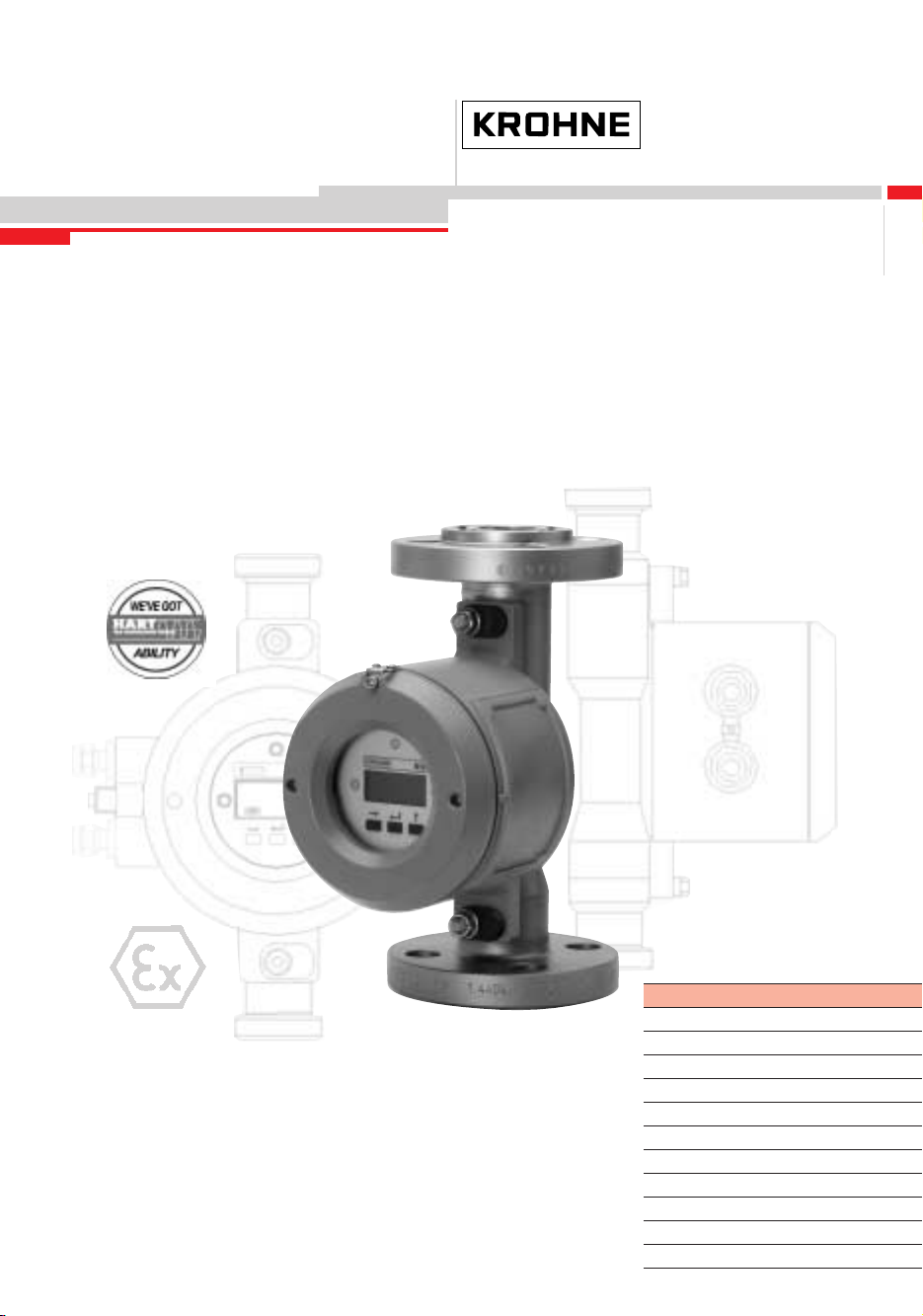
Supplementary Installation and
Operating Instructions
Variable-area flowmeters H250/H54
Signal converter M10
of hazardous-duty
design EEx d
PTB 01 ATEX 1154
©
KROHNE 11/2002 7.02247.22.00
GR
Stand: 08/2000
ANL. A.1 EG-Baumusterprüfbescheinigung PTB 00 ATEX 2063
Variable area flowmeters
Vortex flowmeters
Flow controllers
Electromagnetic flowmeters
Ultrasonic flowmeters
Mass flowmeters
Level measuring instruments
Communications engineering
Engineering systems & solutions
Switches, counters, displays and recorders
Heat metering
Pressure and temperature
Page 2

Contents
1
General safety information .................................................................................................. 3
2 Safety-relevant type code .................................................................................................... 4
3 Main safety-relevant characteristics ................................................................................... 4
3.1 Process products .................................................................................................................... 4
3.2 Category / Zone allocation ......................................................................................................4
3.3 Type of protection ................................................................................................................... 4
3.4 Special lock............................................................................................................................. 4
3.5 Cable entries / sealing plugs...................................................................................................5
3.6 Power supply .......................................................................................................................... 5
3.7 I/O functions............................................................................................................................ 5
3.8 Ambient temperatures / temperature classes ......................................................................... 5
4 Marking.................................................................................................................................. 6
5 Mounting and installation .................................................................................................... 6
5.1 Electrical connection............................................................................................................... 7
5.1.1 General................................................................................................................................... 7
5.1.2 Terminal compartment............................................................................................................7
5.1.3 Connecting cables .................................................................................................................. 7
5.1.4 Connection of power and I/O function..................................................................................... 7
6 Initial startup ......................................................................................................................... 9
7 Operation............................................................................................................................... 9
8 Preventive maintenance....................................................................................................... 9
8.1 Maintenance ........................................................................................................................... 9
8.2 Dismantling ........................................................................................................................... 10
8.2.1 General................................................................................................................................. 10
8.2.2 Replacement of signal converter / display ............................................................................ 10
8.2.3 Replacement of complete device .......................................................................................... 10
Attachment A.1 EC Type Test Certificate PTB 01 ATEX 1154................................................. 11
Attachment A.2 Declaration of Conformity ............................................................................... 19
If you need to return a device for testing or repair to KROHNE.............................................. 20
2
Signal converter M10-EEx d – Supplementary instructions 11/2002
Page 3
1 General safety information
These additional “Ex“ Instructions apply to the hazardous-duty versions of H..../..../M10-EEx
variable-area flowmeters. They are supplementary to the Installation and Operating Instructions for
the non-hazardous-duty versions.
The information given in these Instructions contains only the data relevant to explosion protection.
The technical details given in the Installation and Operating Instructions for the non-hazardousduty version apply unchanged unless excluded or superseded by these Instructions.
In compliance with European Directive 94/9 EG (ATEX 100a), variable-area flowmeters of the
H..../..../M10-EEx series are certified in conformity with European Standards EN 50xxx for use in
hazardous areas under
PTB 01 ATEX 1154
by the Physikalisch-Technische Bundesanstalt (PTB).
This certification together with its boundary conditions is required to be observed without fail (see
Attachment A.1 ”EC type test certificate“).
IMPORTANT!
Mounting, installation, (initial) startup and maintenance work may only be carried out
by personnel who have received "training in explosion protection"!
Maintenance work of a safety-relevant nature within the meaning of explosion protection
may only be carried out by the manufacturer, his authorized representative or under the
supervision of authorized inspectors.
Note!
For processes involving combustible and highly flammable products, easily removable
threaded connections to DIN 11851; SMS; TriClamp (e.g. DIN 32676; ISO 2852 Clamp);
are not allowed.
11/2002
Signal converter M10-EEx d – Supplementary instructions 3
Page 4

2 Safety-relevant type code
The safety-relevant type code is made up of the following elements:
(1)
H .... / .... / M10 - E Ex
1 2 3 4 5
1 : Model series : measuring section
H54
H250
H250C
2 : Material of wetted parts
RR
HC
Ti
PTFE
3 : Model series : indicator section
M10
4 : Territorial application of the approval
E:
5 : Safety function
Ex:
(1)
places for items not needed may be omitted from the type code
: measuring section, Series H54
: measuring section, Series H250
: measuring section, Series H250C
: stainless steel
: Hastelloy
: titanium
: PTFE, ceramics
: signal converter M10
Europe (EC, CENELEC area of validity)
explosion-protected electrical equipment
3 Main safety-relevant characteristics
The H..../..../M10-EEx variable-area flowmeter consists of a combination of signal converter and
measuring tube. The main characteristics of the explosion-protected version are described below.
3.1 Process products
Flammable products are allowed provided they are not present in potentially explosive form.
3.2 Category / Zone allocation
The H..../..../M10-EEx variable-area flowmeter is basically designed in Category 2 for use in
Zone 1.
3.3 Type of protection
The H..../. .../M10-EEx variable-area flowmeters bear the following marking: EEx d IIC T6
3.4 Special lock
The sealing covers of the electronics compartment are secured by a special lock. The locking
screw requires use of an Allen key (3 mm size).
4
Signal converter M10-EEx d – Supplementary instructions 11/2002
Page 5
3.5 Cable entries / sealing plugs
Cable entries and sealing plugs must, in ready-to-operate condition, satisfy the IP Class of
Protection IP67 and each be separately certified in conformity with EN 50 018. Any requirements
specified in the test certificates of the components shall be observed.
3.6 Power supply
Type H..../..../M10-EEx variable-area flowmeters do not require any separate power source. The
necessary supply is obtained via the current output.
3.7 I/O functions
When connecting the I/O interfaces of the H..../..../M10-EEx variable-area flowmeters, the
following values need to be taken into account.
I/O function
(1)
Nominal values of the non- Added restriction
certified receiver instrument
See Standard Installation See Standard Installation Supply power for receiver
and Operating Instructions and Operating Instructions instruments max. 253V
(1)
Only for connection to circuits with “functional extra-low voltage with protective separation
(PELV)”
Peak values U
≤ 25V ; UDC ≤ 60V
AC
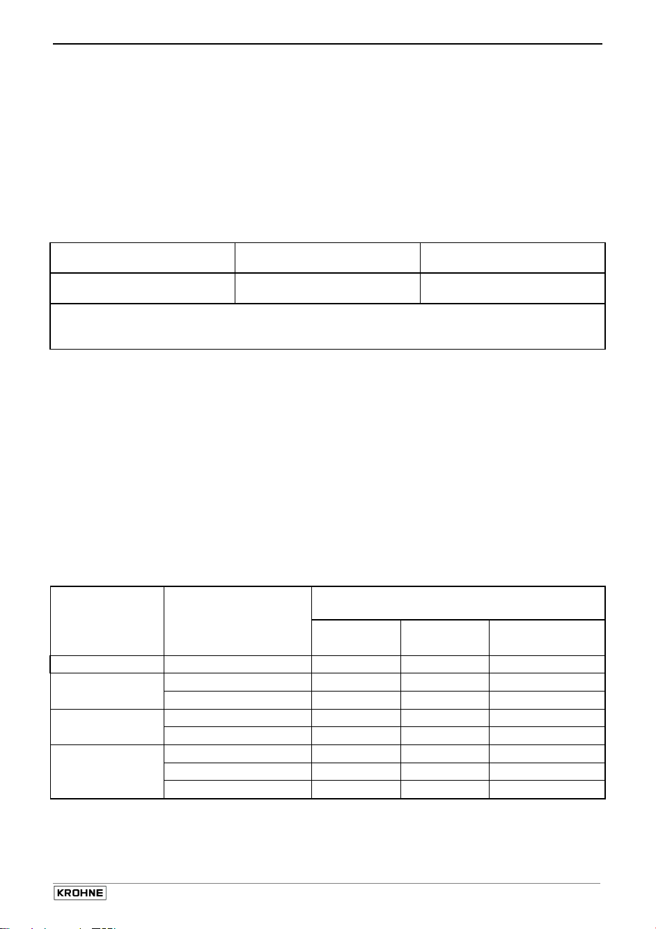
3.8 Ambient temperatures / temperature classes
The permissible ambient temperature for the variable-area flowmeters is limited to a value
≤ 60 °C.
of T
amb
With regard to maximum surface temperatures, variable-area flowmeters are exposed to three
heat sources:
Ambient temperature T
•
Electric power loss Pv
•
Process temperature Tm
•
Accordingly, at a given maximum ambient temperature (T
loss (P
≤ 3 W), we obtain maximum surface temperatures as a factor of the process temperature.
v
For that reason, the devices are not allocated to any specific temperature class; rather, the
temperature class of the devices is a function of the actual process temperature and ambient
temperature, see table below.
Temperature
Ambient temperature
class
T6 -40 … +60 85 85 85
T5 -40 … +50 100 100 100
-40 … +60
T4 -40 … +50 135 135 135
-40 … +60
T3 ... T1 -40 … +40
-40 … +50
-40 … +60
Table 1
Max. permissible process temperatures
The cable glands and line entries must have the same degree of thermal
stability as the connecting cable
amb
in °C
≤ 60°C) and a given maximum power
amb
Max. permissible process
permanent temperature
Wiring Wiring Wiring
70°C 80°C 90°C
85 100 100
85 135 135
180 200 200
135 190 200
85 145 200
11/2002
Signal converter M10-EEx d – Supplementary instructions 5
Page 6
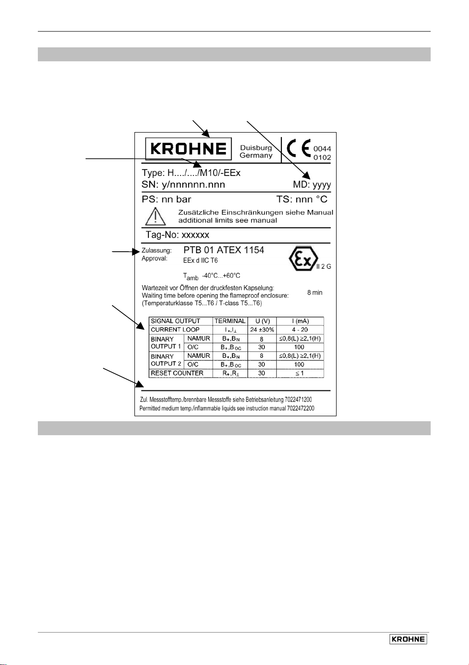
4 Marking
The variable-area flowmeters are identified by an adhesive label or metal plate attached to the
signal converter. The type code is explained in Section 2.
H..../..../M10- EEx, Category 2G
Manufacturer Year of manufacture
Type
Approval
information
Technical
data of
circuits
Safety
info
5 Mounting and installation
Mounting and installation to be carried out in conformity with the valid installation standards for
hazardous areas (e.g. EN 60079-14 / VDE 0165) by specialist personnel trained in explosion
protection.
The information given in the standard Installation and Operating Instructions, the Supplementary
Installation and Operating Instructions (Ex) and also in the EC type test certificate (see Attachment
A.1) must be observed without fail.
Verify that the variable-area flowmeter is suitable for the application in question by comparing
the details on the nameplate with those in Section 3.2 (Categories / Zone allocation), Section 2
(Type code) and Section 4 (Marking).
When installing, please pay special attention to the following points.
6
Signal converter M10-EEx d – Supplementary instructions 11/2002
Page 7

5.1 Electrical connection
5.1.1 General
Insulation rating
The insulation of variable-area flowmeters H..../..../M10 - EEx is rated in conformity with
VDE 0110-1/04.97, equivalent to IEC 60 664-1, and takes into account the following ratings:
• Overvoltage category for signalling and measurement circuits: II
• Insulation contamination level: 2
HAZARDOUS-DUTY Systems
• The signal converter to be incorporated in the equipotential bonding system via the external
PA (equipotential bonding) connection.
• The electrical connection of the variable-area flowmeters to be made as a fixed installation.
5.1.2 Terminal compartment
The electrical connection of the power supply and I/O functions is made in the integrated terminal
compartment of the signal converter. The terminal compartment is designed in EEx d type of
protection. Unassigned openings to be sealed in conformity with EN 50 018.
The cables can basically be routed into the flameproof terminal compartment in one of two ways.
Direct entry of the connecting cables by way of certified flameproof cable glands into the
•
flameproof terminal compartment (V ≤ 2000 cm³). The cable glands must possess a separate
test certificate to EN 50 018. The requirements specified in the test certificate for the cable
gland need to be observed.
Direct entry of the power cables by way of conduits into the flameproof terminal compartment
•
of the device. After the conduit has been screwed in, this must together with the housing form
a flameproof joint with a minimum of 8mm depth of engagement. A suitable stopping box shall
be provided in accordance with the regulations for electrical installations. Installation of the
conduit must be carried out in compliance with its separate test certificate.
5.1.3 Connecting cables
The connecting cables shall be selected in keeping with the valid installation standards
(e.g. EN 60079-14 / VDE 0165). The outside diameter of the cables must match the cable
clamping area for the cable entries.
5.1.4 Connection of power and I/O function
Before connecting or disconnecting the electrical interconnecting cables of the device, make
•
sure that all cables leading to the signal converter are isolated from the ground (reference
potential) of the hazardous area. This also applies to safety conductors (PE) and equipotential
bonding conductors (PA).
All cores and shields of the connecting cables not safety-connected to the equipotential
•
bonding system for the hazardous area should be carefully insulated from each other and
from ground (test voltage 1500V
for conductors of non-intrinsically safe cables).
rms
11/2002
Signal converter M10-EEx d – Supplementary instructions 7
Page 8

Connect the shields by the shortest possible route to the press-fitted U-clamp terminal (PE) in
•
the terminal compartment. If shields are to be grounded at both ends (e.g. for EMC reasons),
adequate equipotential bonding is required between the two shield ends to avoid
unacceptable equalizing currents.
The signal converter must be incorporated in the equipotential bonding system of the
•
hazardous area. The cable is to be connected to the outer press-fitted U-clamp terminal in the
converter housing.
The measuring tube can be incorporated in the equipotential bonding system of the
•
hazardous area by means of the U-clamp terminal (if provided) in the flange or by means of
conductive connections (gaskets, etc.).
The terminal assignment is listed in the following table:
Function Terminal designation
Signal output (see sketch)
Current output HART (current loop) I+
Status output (1) NAMUR B+ B
(binary output 1) O/C-PNP B+ B
Status output (2) NAMUR B+ B
(binary output 2) O/C-PNP B+ B
Status input (reset counter) R+
I
⊥
N
OC
N
OC
R
⊥
Note the electrical data of the circuits given in Section 3.7! Even when operated in the nonhazardous area, the requirements pertaining to the signal output circuits need to be met.
R
+
R
Reset
counter
B
+
B
N
Binary
output 2
B
OC
Achtung!
CAUTION!
Rohrleit ungsadapter v erwenden.
APPLY C ERTIFIED C ABLE ENTRI ES OR
Nur bescheinigte Leitungseinführungen bzw.
B
+
B
N
Binary
output 1
B
CONDUIT ADAPTORS ONLY.
OC
I
+
loop
I
Current
8
Signal converter M10-EEx d – Supplementary instructions 11/2002
Page 9

6 Initial startup
Check the following points before initial startup:
Suitability of the materials used for the measuring tube and gaskets for adequate resistance
•
to corrosion through the process product.
Compare the data on the nameplate on the signal converter with the existing operating data.
•
Check that the measuring tube has been correctly installed in the pipeline.
•
Check that the equipotential bonding system is properly connected.
•
Check correct connection of the power cables.
•
Check that the cover(s) of the electronics compartment is firmly in place, that the special lock
•
is tightened down.
7 Operation
It is not permitted to open the cover of the electronics compartment during operation and in the
presence of an explosive atmosphere.
Should parameterization of the device become necessary in the presence of an explosive
atmosphere, this can be done by applying the supplied programming bar magnet to the glass
window of the electronics compartment, without opening the housing, or digitally by way of the
signal output (HART interface).
In the case of flammable products, the measuring sections shall be included in the periodic
pressure testing of the plant.
8 Preventive maintenance
8.1 Maintenance
The signal converter does not require any maintenance under normal operating conditions and
when used for the intended purpose. Within the scope of checks required to be carried out in
hazardous areas to maintain systems in proper working order, the following visual inspections
should be carried out at regular intervals:
Inspection of the housing, cable entries and incoming cables for signs of corrosion and
•
damage,
Check of pipe connections for leakages.
•
11/2002
Signal converter M10-EEx d – Supplementary instructions 9
Page 10

8.2 Dismantling
8.2.1 General
Should it prove necessary to open the Flameproof Enclosure of the electronics compartment in the
presence of an explosive atmosphere, the device must first be disconnected from supply. Be sure
to allow the waiting time printed on the nameplate of the signal converter of:
8 minutes for temperature classes T6 and T5
•
to elapse before opening the Flameproof Enclosure. There is no waiting time for any of the other
temperature classes.
Before connecting or disconnecting the device interconnecting cables, make sure that all cables
leading into the signal converter are isolated from the ground (reference potential) of the
hazardous area. This also applies to safety conductors (PE), functional ground (FE) and the
equipotential bonding conductor (PA).
After any maintenance work has been carried out, be sure to regrease the thread of the
flameproof cover of the signal converter, including cover gaskets, with a resin-free and acid-free
all-purpose grease.
8.2.2 Replacement of signal converter / display
Disconnect the device from supply before opening the Flameproof Enclosure. Be sure to follow the
procedure described in Section 8.2.1.
Note :
The display can be replaced after opening the Flameproof Enclosure of the electronics
compartment. To replace a complete display, take note of the information given in Section 5.1.4.
The measuring tube of the variable-area flowmeter can in both cases remain in the pipeline, also
when product is flowing.
Note :
Only same-type displays and complete converter housings may be replaced.
Individual device inserts may not be replaced! Compare nameplates when
replacing the signal converter. Only same-type signal converters to be replaced.
Always renew defective fastening clips (prisms) between measuring tube and
display housing.
8.2.3 Replacement of complete device
Please refer to Sections 8.2.1 and 8.2.2. In addition, make sure that all process connections and
the pipeline are non-pressurized and free of product. In the case of environmentally critical
substances, carefully decontaminate the wetted parts of the flange system after dismantling.
10
Signal converter M10-EEx d – Supplementary instructions 11/2002
Page 11

Attachment A.1
EC Type Test Certificate PTB 01 ATEX 1154
11/2002
Signal converter M10-EEx d – Supplementary instructions 11
Page 12

Attachement A.1
EC Type Test Certificate PTB 01 ATEX 1154
Physikalisch-Technische Bundesanstalt
PTB
Brunswick and Berlin
(1)
(2) Devices and protective systems for use as prescribed
in hazardous areas - Directive 94/9/EC
(3) EC Type Test Certificate Number
PTB 01 ATEX 1154
(4) Device: Variable-area flowmeter H…./…./M10-EEx
(5) Manufacturer: KROHNE Messtechnik GmbH & Co. KG
(6) Address: Ludwig-Krohne-Str. 5, 47058 Duisburg, Germany
(7) The design of this device as well as the variously approved versions are defined in the
Schedule to this Type Test Certificate and in the documents listed in the Schedule.
(8) The Physikalisch-Technische Bundesanstalt, being the notified body No. 0102 in
accordance with Article 9 of the Council Directive of European Communities dated
23rd March 1994 (94/9/EC), certifies that the basic health and safety requirements
have been satisfied for the conception and construction of devices and protective
systems for use as prescribed in hazardous areas in accordance with Appendix II of
said Directive.
The results of the test are specified in the confidential test report PTB Ex 01-11294.
(9) The basic health and safety requirements are satisfied by conformity with
EN 50014:1997 + A1 + A2 EN 50018:2000
(10) If the character “X“ is appended to the certificate number, this refers to special
conditions for the safe application of the device as given in the Schedule to this
Certificate.
(11) This EC Type Test Certificate applies only to the conception and construction of the
defined device in accordance with Directive 94/9/EC. Further requirements of said
Directive apply to the manufacture of that device and to putting it on the market. Such
requirements are not covered by this Certificate.
(12) The marking of the device must include the following details:
EC Type Test Certificate
Certification Agency for Explosion Protection Brunswick, 30st September 2002
on behalf of Official stamp
(signed) of the PTB
Dr.-Ing. U. Klausmeyer
Regierungsdirektor
Page 1/4
12
Signal converter M10-EEx d – Supplementary instructions 11/2002
II 2 G EEx d IIC T6 … T1
Page 13

11/2002
Signal converter M10-EEx d – Supplementary instructions 13
Page 14

Physikalisch-Technische Bundesanstalt
PTB
Brunswick and Berlin
(13)
(14)
(15) Device description
The H…./…./M10-EEx variable-area flowmeter is designed to measure the volume rate of flow
of flammable and non-flammable gases and liquids in vertical pipe runs. The flow through the
measuring tube is from bottom to top, and the guided float adjusts so that lifting force, form
resistance and float weight are in equilibrium. Every vertical position of the float thus
corresponds to a specific flow rate. Electromagnetic position sensors in the display section
convert the position of the float into an appropriate electrical output signal.
Technical data
Supply (functional extra-low voltage PELV, U
Signal output 4 – 20 mA U
(terminal I
Signal output 1 & 2 NAMUR circuit
Output 1 (terminal B
Output 2 (terminal B
or
Output 1 (terminal B
Output 2 (terminal B
U
Status input U
(terminal R
Protection against ingress of
foreign bodies and water IP 67 in conformity with EN 60529
(16) Test report
Page 2/4
EC Type Test Certificate PTB 01 ATEX 1154
, I⊥) HART communication
+
, BN) UN = 8 V DC, depending on switch position ≤ 0.8 mA or
+
, BN)
+
, BOC ) open collector (pnp output)
+
, BOC ) UN = 8 ... 30 V DC; Ii ≤ 100 mA;
+
, R⊥)
+
PTB Ex 01-11294
S c h e d u l e
= 24 V DC + 30%, 2-wire connection with
N
≥
2.1 mA; Ri = 1 kΩ
with effectively conducting output ≤ 3 V
I
= 8 … 30 V DC; Ii ≤ 1 mA
N
≤ 60 V)
DC
14
Signal converter M10-EEx d – Supplementary instructions 11/2002
Page 15

11/2002
Signal converter M10-EEx d – Supplementary instructions 15
Page 16

Physikalisch-Technische Bundesanstalt
PTB
Brunswick and Berlin
Schedule to EC Type Test Certificate PTB 01 ATEX 1154
(17) Special conditions
none.
Additional directions for safe operation
Connection conditions
1. The H…./…./M10-EEx variable-area flowmeter shall be connected up via suitable
cable glands and/or conduit systems that satisfy the requirements of EN 50018
Sections 13.1 and 13.2 and for which a separate test certificate is to hand.
2. Cable glands and entry fittings (screwed conduit entries) as well as blanking plugs
of simple design may not be used. On connection of the H…./…./M10-EEx
variable-area flowmeter using a conduit entry approved for the purpose, the
associated sealing facility must be arranged directly on the housing.
3. Unused openings shall be closed off as defined in EN 50018 Section 11.9.
4. The connecting cable of the variable-area flowmeter shall be permanently installed
and in such as manner as to be adequately protected against damage.
These directions shall in suitable form accompany each apparatus.
Equipotential bonding
The H…./…./M10-EEx variable-area flowmeter shall be incorporated in the local
equipotential bonding system.
Permissible ambient and process temperatures as a factor of the temperature
class
Temperature
class
T6 -40 … +60 85 85 85
T5 -40 … +50 100 100 100
T4 -40 … +50 135 135 135
T3 ... T1 -40 … +40
Ambient temperature in
°C
-40 … +60
-40 … +60
-40 … +50
-40 … +60
Max. permissible process
permanent temperature
Wiring Wiring Wiring
70°C 80°C 90°C
85 100 100
85 135 135
180 200 200
135 190 200
85 145 200
The cable glands and line entries must have the same degree of thermal stability as the
connecting cable.
Page 3/4
16
Signal converter M10-EEx d – Supplementary instructions 11/2002
Page 17

11/2002
Signal converter M10-EEx d – Supplementary instructions 17
Page 18

Physikalisch-Technische Bundesanstalt
PTB
Brunswick and Berlin
Schedule to EC Type Test Certificate PTB 01 ATEX 1154
General directions
Flammable products are allowed provided they do not form any potentially explosive
gas mixture inside the plant. When operated with flammable products, the measuring
sections shall be included in the routine plant pressure tests.
Before the Flameproof Enclosure of the electronics compartment is opened, a waiting
time of at least 8 minutes shall be allowed to elapse in respect of temperature classes
T5 and T6.
(18) Basic health and safety requirements
are satisfied by conformity with the afore-mentioned standards.
Certification Agency Brunswick, 30st September 2002
for Explosion Protection
On behalf of Official stamp
(signed) of the PTB
Dr.-Ing. U. Klausmeyer
Regierungsdirektor
Page 4/4
18
Signal converter M10-EEx d – Supplementary instructions 11/2002
Page 19

Attachment A.2 Declaration of Conformity
11/2002
Signal converter M10-EEx d – Supplementary instructions 19
Page 20

If you need to return a device for testing or repair to KROHNE
Your instrument has been carefully
manufactured and tested. If installed and
operated in accordance with these operating
instructions, your instrument will rarely present
any problems. Should you nevertheless need
to return an instrument for checkout or repair,
please pay strict attention to the following
points:
Due to statutory regulations concerning
protection of the environment and
safeguarding the health and safety of our
personnel, KROHNE may only handle, test and
repair returned instruments that have been in
contact with liquids if it is possible to do so
without risk to personnel and environment.
This means that KROHNE can only service
your instrument if it is accompanied by a
certificate in line with the following model
confirming that the instrument is safe to
handle.
Specimen certificate
Company:........................................................... Address:.................................................................
Department: ....................................................... Name: ....................................................................
Tel. No.: ............................................................. Fax No.: .................................................................
The enclosed instrument
Type: .................................................................. .: .............................................................................
KROHNE Order No. or Series No ...................... ...............................................................................
has been operated with the following process liquid
Because this process liquid is
water-endangering * / toxic * / caustic * / flammable*
we have
- checked that all cavities in the instrument are free from such substances *
- flushed out and neutralised all cavities in the instrument *
(* delete where not applicable)
We confirm that there is no risk to man or environment through any residual liquid contained in the
instrument.
Date: .................................................................... Signature..............................................................
.............................................................................
Company stamp:
If the instrument has been operated with toxic,
caustic, flammable or water-endangering liquids,
you are kindly requested
•
to check and ensure, if necessary by rinsing
or neutralising, that all cavities in the
instrument are free from such dangerous
substances.
(Directions on how you can find out whether
the primary head has to be opened and
flushed out or neutralised are obtainable
from KROHNE on request.)
•
to enclose a certificate with the instrument
confirming that the instrument is safe to
handle and stating the liquid used.
KROHNE regret that they cannot service your
instrument unless it is accompanied by such a
certificate.
...............................................................................
20
Signal converter M10-EEx d – Supplementary instructions 11/2002
 Loading...