

Page 1
Supplementary instructions
Supplementary instructions
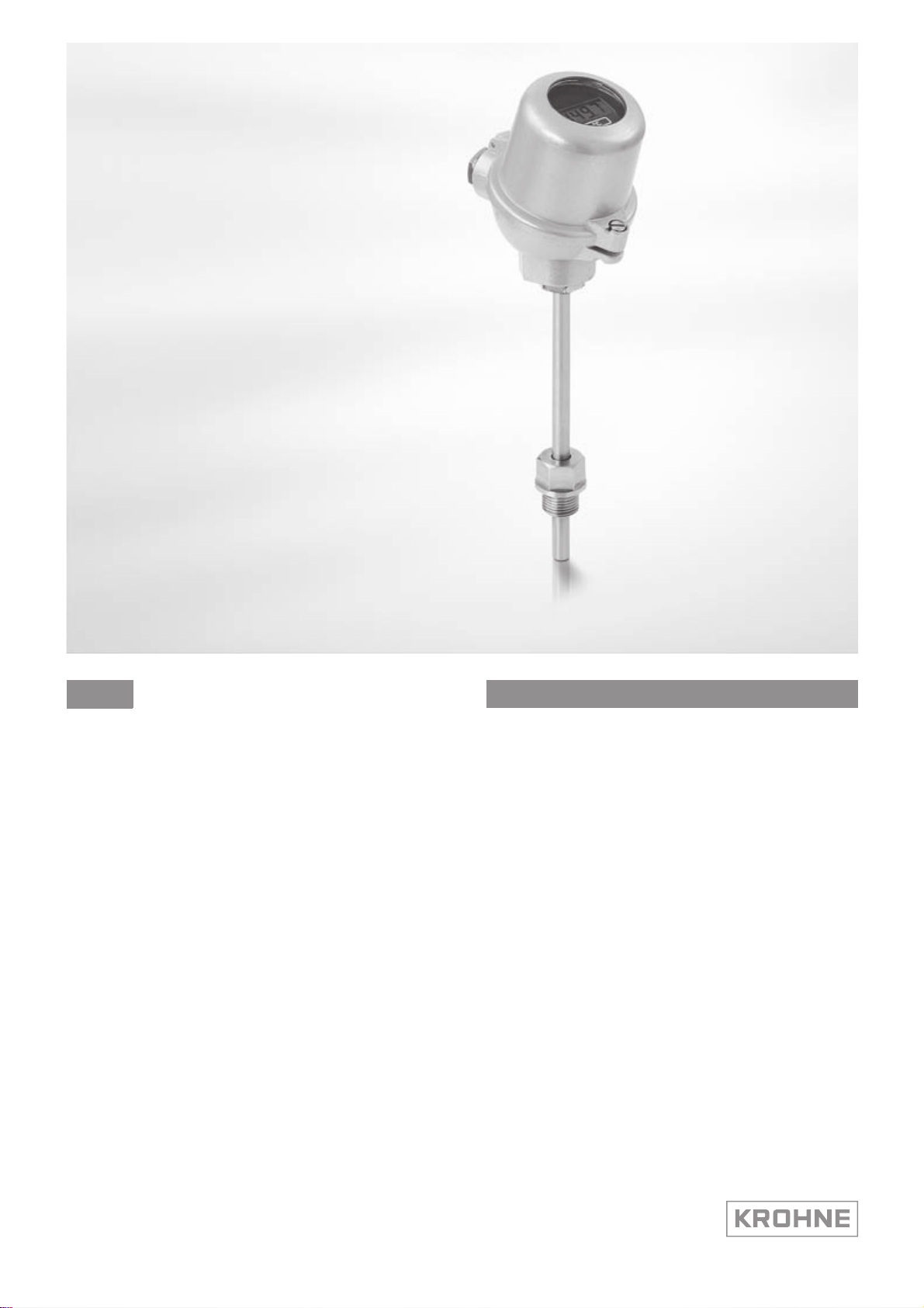
OPTITEMP LCD-H20
OPTITEMP LCD-H20
OPTITEMP LCD-H20OPTITEMP LCD-H20
Loop powered LCD indicator for in-head mounting of
industrial thermometers
Supplementary instructions Supplementary instructions
© KROHNE 11/2011 - 4001594702 - AD OPTITEMP LCD-H20 R02 en
Page 2

CONTENTS
OPTITEMP LCD-H20
1 Safety instructions 3
1.1 Scope of the document..................................................................................................... 3
1.2 Intended use ..................................................................................................................... 3
2 Device description 4
2.1 Device description ............................................................................................................ 4
2.2 Technical data................................................................................................................... 4
2.3 Dimensions ....................................................................................................................... 5
3 Installation 6
3.1 Mounting in the connection head ..................................................................................... 6
3.2 Configuration .................................................................................................................... 6
3.2.1 Programming procedure ........................................................................................................ 6
3.2.2 Setting the decimal point (dP) ................................................................................................ 7
3.2.3 Setup of the zero point (ZErO) ................................................................................................ 7
3.2.4 Setup of the span (SPAn) ........................................................................................................7
3.2.5 Limit of the indicator range (Li) .............................................................................................. 7
3.2.6 Setup of the filter (FiLT).......................................................................................................... 8
3.2.7 Setup of the resolution (riS).................................................................................................... 8
3.2.8 Summary................................................................................................................................. 8
4 Electrical connections 9
4.1 Connection diagram .........................................................................................................9
5 Operation 10
5.1 Normal mode.................................................................................................................. 10
5.2 Calibration ...................................................................................................................... 10
6 Service 11
6.1 Service ............................................................................................................................ 11
6.2 Ordering information...................................................................................................... 11
2
www.krohne.com 11/2011 - 4001594702 - AD OPTITEMP LCD-H20 R02 en
Page 3

OPTITEMP LCD-H20
1.1 Scope of the document
These Supplementary Instructions apply solely to the installation of the LCD-H20 indicator. The
technical details given in the handbook for industrial thermometers apply unchanged unless
excluded or superseded by these Instructions.
1.2 Intended use
The LCD-H20 indicator is a digital display to be installed in the 4…20 mA loop without the need
for an additional external power supply.
SAFETY INSTRUCTIONS 1
www.krohne.com11/2011 - 4001594702 - AD OPTITEMP LCD-H20 R02 en
3
Page 4

2 DEVICE DESCRIPTION
2.1 Device description
The LCD-H20 indicator is designed for installation in a thermometer connection head with
window. The indicator features 12 mm LCD digits.
The indication range is adjustable between -1999 and 9999 using three pushbuttons. No
additional supply power is required.
As a rule, the LCD-H20 indicator is delivered pre-installed in a BUZ-HW connection head.
2.2 Technical data
Current input 4...20 mA
Operating range of the indicator 3.6 ...22 mA
Voltage drop 2.5 V
Display 4 digits incl. minus sign
Indication range Scaleable from -1999 to 9999 as well as 0 to 3 decimal places
Scale setting Using 3 pushbuttons
Ambient temperature range -20...+70°C / -4...+158°F
Typical accuracy ±0.1% of programmed span ±1 digit
Cable thickness
Mounting kit KDST1 suitable for BUZ-HW connection head
Weight (only LDC-H20) 30 g / 0.07 lb
Weight (BUZ-HW connection
head and LDC-H20)
OPTITEMP LCD-H20
12 mm high
≤ 1.0 mm2, AWG 16
375 g / 0.8 lb
4
www.krohne.com 11/2011 - 4001594702 - AD OPTITEMP LCD-H20 R02 en
Page 5

OPTITEMP LCD-H20
2.3 Dimensions
Figure 2-1: Installation dimensions of loop powered indicator
DEVICE DESCRIPTION 2
[mm] ["]
a 17 0.67
b Ø59 Ø2.32
c 34 1.34
d 13.5 0.53
e 49 1.93
www.krohne.com11/2011 - 4001594702 - AD OPTITEMP LCD-H20 R02 en
5
Page 6

3 INSTALLATION
3.1 Mounting in the connection head
Figure 3-1: Installing the loop powered indicator into the BUZ-HW connection head
1 Polycarbonate window
2 Loop powered indicator LCD-H20
3 Mounting kit KDST1
4 M20 x 1.5
OPTITEMP LCD-H20
3.2 Configuration
3.2.1 Programming procedure
Programmed using the 3 pushbuttons located on the bottom of the indicator. The middle key is
the enter key (F), the two outer keys with the up and down arrows are used to select various
parameters. Positioning of the Keys on page 9.
Key Function
FFFF Calling up programming mode.
Switching between parameter and set value.
Save values.
Decrease by one digit
Selecting or setting a parameter.
Increase by one digit.
Selecting or setting a parameter.
+ Exit programming mode.
Cancel.
6
www.krohne.com 11/2011 - 4001594702 - AD OPTITEMP LCD-H20 R02 en
Page 7

OPTITEMP LCD-H20
• Hold F key down for longer than 3 s to access programming mode.
i The indicator displays the "dP" function, the first programming function in the menu: setup
of the decimal point for the indicator.
• It is possible to switch back and forth between the individual programming menus by pressing
the key (increase) and the key (decrease).
• Hold the F-key down again to change the selected parameters
• At the end of each programming session, any changed parameters must be saved by pressing
the F key.
i Saved values are retained even after the display has been switched off.
3.2.2 Setting the decimal point (dP)
• Press the or key to set the position of the decimal point in the range of 0 to 3 digits after
the decimal point.
• Press the F key to confirm.
INFORMATION!
The factory default setting is one decimal place after the point.
INSTALLATION 3
3.2.3 Setup of the zero point (ZErO)
• Press the or key to set the zero point of the indicator within the range of -1999 to 9999.
• Press the F key to confirm.
INFORMATION!
The factory default setting of the zero point is 0.0
3.2.4 Setup of the span (SPAn)
• Press the or to set the span, or measuring range of the indicator, within the limits of
-1999 to 9999.
• Press the F key to confirm.
INFORMATION!
The factory default setting is a span of 100.0.
3.2.5 Limit of the indicator range (Li)
This parameter is used to set the overload limit of the displayable range.
• When the parameter is set to "Li = 0
"+OL" is displayed. "-OL" is displayed when the current is less than 4 mA.
• When the parameter is set to "Li = 1
limits of 4...20 mA before "+OL" or "-OL" is displayed.
°
C.
Li = 0" and the current exceeds a value of 20 mA, the message
Li = 0Li = 0
Li = 1", the displayable range is increased by 10% beyond the
Li = 1Li = 1
INFORMATION!
The factory default setting is "Li = 1".
www.krohne.com11/2011 - 4001594702 - AD OPTITEMP LCD-H20 R02 en
7
Page 8

3 INSTALLATION
3.2.6 Setup of the filter (FiLT)
When there is interference with the 4...20 mA signal, it is possible to set a higher filter value
"FiLt" in order to obtain a more stable and accurate display.
• Press the key to increase the filter value and the key to decrease the filter value.
• Filter values ranging from 1 to 8 can be set where "FiLt = 1" represents a switched off filter
and the display value is updated in this case every 250 ms.
• If "FiLt > 1", the update time of 250 ms is multiplied by the respective set filter value. If, for
example, "FiLt = 5" the display value is updated every 1.25 s.
INFORMATION!
The factory default setting is "FiLt = 2".
3.2.7 Setup of the resolution (riS)
This function is used to set the resolution of the display. Adjustable values for "riS" are: 1, 2, 5
and 10
OPTITEMP LCD-H20
• When "riS = 1" all possible digits within the programmed measuring range are shown
continuously.
• When "riS = 2", the steps of two consecutive values are doubled, i.e. odd values can then no
longer be displayed (0, 2, 4, 6, 8,…).
INFORMATION!
It is recommended that the resolution only be reduced when the measuring range is extremely
large, e.g. 10000 points or when the 4...20 mA signal is very unstable. If that is not the case, the
maximum resolution is always set: "riS = 1". That corresponds to the factory default setting.
3.2.8 Summary
Key Function Display
Change with
or
F Calling up the programming mode, switching between parameters and set value, save
Decrease one digit 9 to 0
Increase one digit 0 to 9
+ Exit programming mode, cancel (without saving)
Setup of the decimal point dP / 000.0
Setup of the zero point ZErO / 0.0
Span (setting the measuring range) SPAn / 100.0
Limit of the indicator range Li / 1
Filter setting FiLT / 2
Display resolution riS / 1
8
www.krohne.com 11/2011 - 4001594702 - AD OPTITEMP LCD-H20 R02 en
Page 9

OPTITEMP LCD-H20
4.1 Connection diagram
ELECTRICAL CONNECTIONS 4
Figure 4-1: Loop powered indicator wiring
1 4...20 mA
2 Power supply 24 VDC
3 Red
4 Black
5 Input
6 Output
7 2-wire transmitter
www.krohne.com11/2011 - 4001594702 - AD OPTITEMP LCD-H20 R02 en
9
Page 10

5 OPERATION
5.1 Normal mode
No settings are carried out on the display in normal mode.
5.2 Calibration
Simultaneously pressing the and keys for longer than 3 s opens the calibration menu. In
the calibration menu it is possible to calibrate the values for the zero point and the span of the
A/D converter on the digital display. Shorten loop circuit before starting calibration, refer to
Connection diagram
CAUTION!
Only trained personnel with the appropriate equipment may adjust these settings. Incorrect
calibration influences the proper functioning of the indicator.
Step 1: Zero point calibration
• Select the C4 calibration procedure for zero point calibration from the calibration menu by
pressing the or key.
• Supply the input of the indicator with a current of 4 mA and wait until the display stabilises.
• Press the F key until "CAL" appears on the display.
i After a few seconds the new value for the zero point is displayed.
OPTITEMP LCD-H20
on page 9, connection 3 and 4.
• Simultaneously press the + keys to exit the "zero point calibration menu" and continue
with full scale calibration.
Step 2: Full scale calibration
• Select the C20 calibration procedure for the measuring range from the calibration menu by
pressing the or key.
• Supply the display input with a current of 20 mA and continue as with the zero point
calibration.
10
www.krohne.com 11/2011 - 4001594702 - AD OPTITEMP LCD-H20 R02 en
Page 11

OPTITEMP LCD-H20
6.1 Service
No service measures are necessary with this indicator.
6.2 Ordering information
Designation Order code
LCD-H20 indicator 70LCDH2001
LCD-H20 indicator mounted in BUZ-HW connection
head
Custom configuration of display 70CAL00001
SERVICE 6
70LCDH2011
www.krohne.com11/2011 - 4001594702 - AD OPTITEMP LCD-H20 R02 en
11
Page 12

KROHNE product overview
• Electromagnetic flowmeters
• Variable area flowmeters
• Ultrasonic flowmeters
• Mass flowmeters
• Vortex flowmeters
• Flow controllers
• Level meters
• Temperature meters
• Pressure meters
• Analysis products
• Measuring systems for the oil and gas industry
• Measuring systems for sea-going tankers
Head Office KROHNE Messtechnik GmbH
Ludwig-Krohne-Str. 5
D-47058 Duisburg (Germany)
Tel.:+49 (0)203 301 0
Fax:+49 (0)203 301 10389
info@krohne.de
© KROHNE 11/2011 - 4001594702 - AD OPTITEMP LCD-H20 R02 en - Subject to change without notice.
The current list of all KROHNE contacts and addresses can be found at:
www.krohne.com
 Loading...