

Page 1
Variable area flowmeters
Vortex flowmeters
Flow controllers
Electromagnetic flowmeters
Ultrasonic flowmeters
Mass flowmeters
Level measuring instruments
Communications technology
Engineering systems & solutions
Switches, counters, displays and recorders
Heat metering
Pressure and temperature
© KROHNE 12/2002 7.30924.31.00
Addition to the
installation and operating instructions
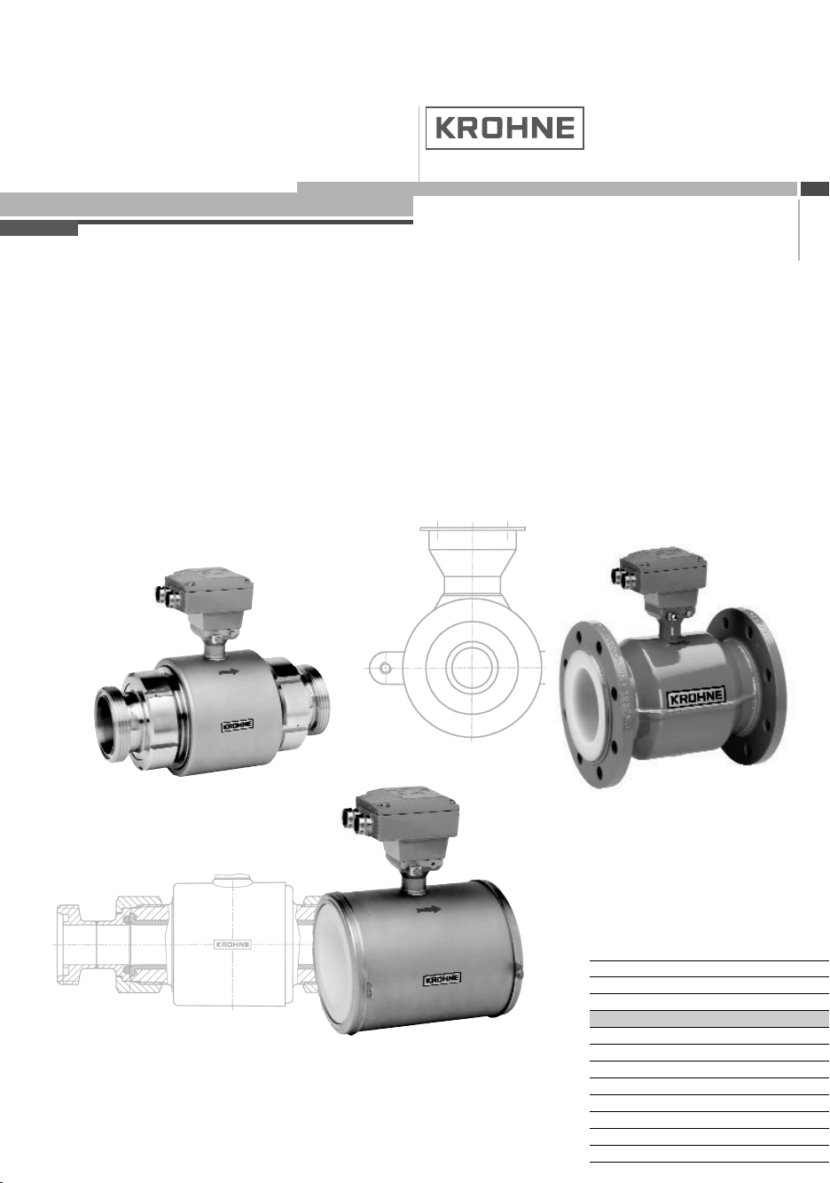
ALTOFLUX IFS 4000 F-EEx
PROFIFLUX IFS 5000 F-EEx
VARIFLUX IFS 6000 F-EEx
Electromagnetic primary head
(remote design)
Page 2
WARNING !
Be sure to follow these instructions !
IMPORTANT !
These additional instructions are an extension to the “Installation and Operating Instructions” and
only apply to the EEx version of the IFS 4000 F, IFS 5000 F and IFS 6000 F electromagnetic
primary heads in remote design. All technical information described in the “Installation and
Operating Instructions” are applicable, when not specifically excluded, completed or replaced by the
instructions in these additional instructions.
No changes regarding safety may be made to the devices. Unauthorized changes
might affect the explosion safety of the devices.
• The prescriptions and regulations as well as the electrical data described in
the EC-type examination certificate must be obeyed.
• Beside the instructions for electrical installations in non-hazardous locations
according to the applicable national standard (e.g. IEC 364), especially the
regulations in EN 60079-14 "Electrical installations in hazardous locations" or
equivalent national standard must be followed.
• Installation, establishment, utilization and maintenance are only allowed to be
executed by personnel with an education in explosion safety !
Contents
1 System components 3
1.1 General information ALTOFLUX IFS 4000 F-EEx 3
1.1.1 Mechanical construction 5
1.1.2 Data plates of ALTOFLUX IFS 4000 F-EEx 5
1.2 General information PROFIFLUX IFS 5000 F-EEx 6
1.2.1 Mechanical construction 7
1.2.2 Data plates of PROFIFLUX IFS 5000 F-EEx 7
1.3 General information VARIFLUX IFS 6000 F-EEx 8
1.3.1 Mechanical construction 9
1.3.2 Data plates of VARIFLUX IFS 6000 F-EEx 9
1.4 Block diagram 10
2 Electrical connection 11
2.1 Primary fuse connection (only for IFS 5000 F-EEx and IFS 6000 F-EEx) 11
2.2 Fuse protection of field coil circuit 11
2.3 Equipotential bonding system 11
2.4 Intermediate junction box ZD-EEx 11
2.5 Connecting cables 12
2.6 Connection diagrams 14
3 Maintenance 16
4 Declaration of conformity 17
5 EC-type examination certificates 18
5.1 ALTOFLUX IFS 4000 F-EEx certificate 18
5.2 PROFIFLUX IFS 5000 F-EEx certificate 24
5.3 VARIFLUX IFS 6000 F-EEx certificate 27
2 ALTOFLUX IFS 4000F-EEx, PROFIFLUX IFS 5000F-EEx, VARIFLUX IFS 6000F-EEx
Page 3

1 System components
1.1 General information ALTOFLUX IFS 4000 F-EEx
The ALTOFLUX IFS 4000 F-EEx electromagnetic primary head in remote design (F = field)
complies with the European Directive 94/9 EC (ATEX 100a) and has been approved for hazardous
classified locations of Zone 1 and 2 by the KEMA conform to the European Standards of the
EN 500xx series.
They have the following approval number:
KEMA 01 ATEX 2263 X
The IFS 4000 F-EEx primary head is designed for ambient temperatures in the range of -40°C up to
+60°C inclusive. The IFS 4000 F-EEx primary head in remote design is connected to an associated
signal converter, e.g. IFC 090 F/…-EEx, which is also approved in accordance with the European
Directive 94/9 EC (ATEX 100a). The signal converter is installed on a distance from the IFS 4000 FEEx primary head and connected via a field coil cable, an electrode cable and a bonding wire.
The IFS 4000 F-EEx primary head in remote design can be installed in environments that are
classified as Zone 1 or Zone 2 hazardous locations. The maximum permissible process liquid
temperature is dependent on the maximum ambient temperature (Ta) that can occur in that
environment too.
For installation of the IFS 4000 F-EEx primary head please conform to the following listed three
temperature classification tables on the next page. The first column lists the temperature classes for
gases and the second one the rating for dusts.
The first table applies to meter sizes larger and equal to DN300, which have type of protection
increased safety "EEx e".
The second table applies to meter sizes DN25 up to DN150 inclusive, which are performed as type
of protection flameproof enclosure "EEx d".
The third table applies to meter sizes DN10-20 (type protection increased safety “EEx e” and
encapsulation “EEx m”) and DN200-300 (increased safety “EEx e” and powder filling “EEx q”).
The following three tables only give the maximum possible temperatures for a lining material inside
the measuring tube of the primary head that consists of PFA. For information on temperature
restrictions of other lining materials, see Standard Installation and Operating Instructions.
ALTOFLUX IFS 4000F-EEx, PROFIFLUX IFS 5000F-EEx, VARIFLUX IFS 6000F-EEx 3
Page 4
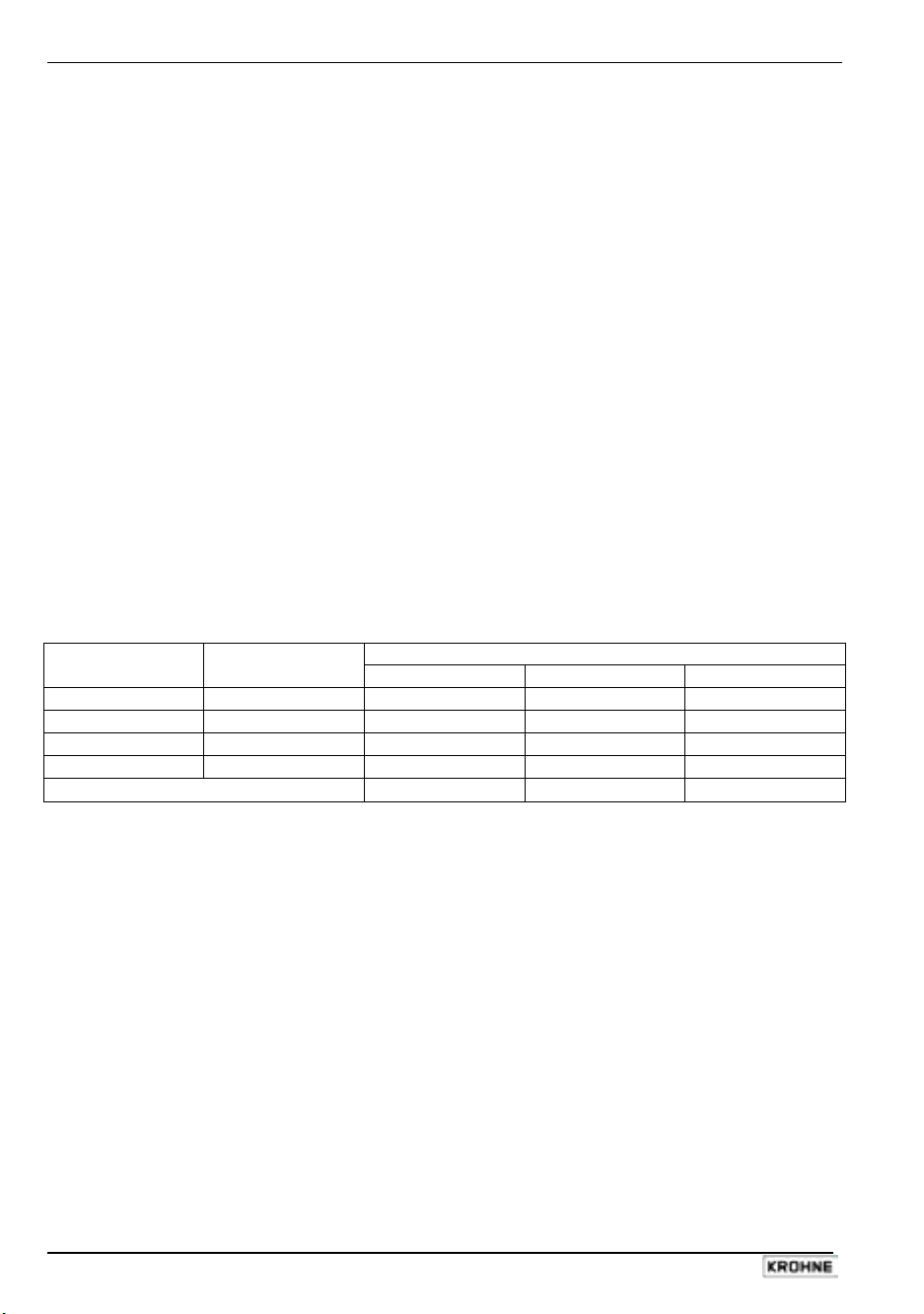
Temperature classification of meter sizes larger than DN300
Max. surface
class
T6
T5
T4
T3
temperature
T 85°C 60°C 60°C 60°C
T100°C 80°C 75°C 75°C
T135°C 115°C 115°C 115°C
T180°C 160°C 150°C 140°C
Use heat-resistant cables above -
Maximum process liquid temperature Temperature
Ta ≤ 40 °C Ta ≤ 50 °C Ta ≤ 60 °C
145°C 110°C
Temperature classification of meter sizes DN25…150
Max. surface
class
T6
T5
T4
T3
temperature
T 85°C 70°C 70°C 70°C
T100°C 85°C 85°C 85°C
T135°C 120°C 120°C 120°C
T180°C 180°C 180°C 180°C
Use heat-resistant cables above -
Maximum process liquid temperature Temperature
Ta ≤ 40 °C Ta ≤ 50 °C Ta ≤ 60 °C
155°C 105°C
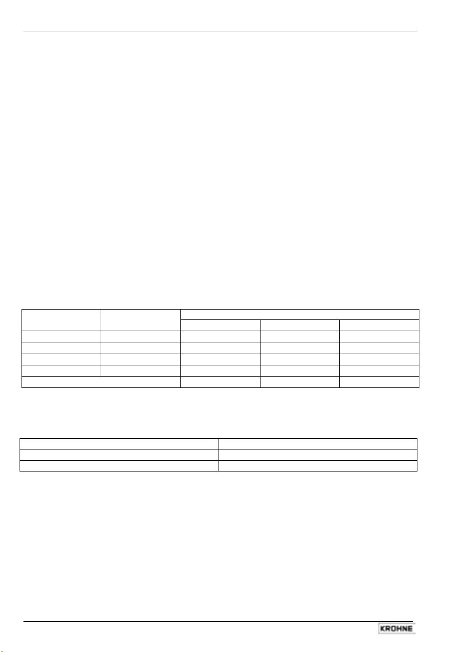
Temperature classification of meter sizes DN10-20 and DN200-300
Maximum process liquid temperature Temperature
Ta ≤ 40 °C Ta ≤ 50 °C Ta ≤ 60 °C
class
T6
T5
T4
T3
Max. surface
temperature
T 85°C 75°C 70°C 70°C
T100°C 95°C 90°C 75°C
T135°C 130°C 115°C 75°C
T150°C 150°C 115°C 75°C
IMPORTANT !
The maximum process liquid temperature values in the above listed tables only
apply to a lining material of PFA (maximum operating temperature of 200°C). For
other lining materials (e.g. rubber) is a lower process liquid temperature required for
safe operation. See the standard Installation and Operating Instructions for
detailed information about other lining materials.
The IFS 4000 F-EEx is marked with one of the following EEx-codes, which depends on the meter
size range (see table below).
Marking IFS 4000 F-EEx-code
Meter size EEx-code
DN10… DN20 II 2GD EEx me ib IIC T6…T3
DN25… DN150 II 2GD EEx de ib IIC T6…T3
DN200…DN300 II 2GD EEx qe ib IIC T6…T3
larger than DN300 II 2GD EEx e ib IIC T6…T3
Also see the EC-type examination certificate in Section 5 of these additional instructions.
4 ALTOFLUX IFS 4000F-EEx, PROFIFLUX IFS 5000F-EEx, VARIFLUX IFS 6000F-EEx
Page 5
1.1.1 Mechanical construction
The IFS 4000 F-EEx primary head is the measuring unit of the flowmetering system (see block
diagram in section 1.4). It contains two field coils and two electrodes in type of protection intrinsic
safety category "ib" according to EN 50020. The type of protection of the field coils depends on the
meter size:
DN10…DN20 Increased safety “e” according to EN 50019 and
encapsulation “m” according to EN 50028
DN25…DN150 Flameproof enclosure “d” according to EN 50018
DN200...DN300 Increased safety “e” according to EN 50019 and
powder filling “q” according to EN 50017
larger than DN300 Increased safety “e” according to EN 50019
The electrode circuits are wired by separate shielded cables and marked by the sheath color (white
and purple). The intrinsical safe "EEx ib" electrode circuits inside the IFS 4000 F-EEx primary head
have the following maximum values (entity parameters):
Maximum input voltage U
Maximum input current I
Maximum internal capacitance C
Maximum internal inductance L
max
max
i
i
= 20 V
= 175 mA
= 0
= 0
The two field coils inside the primary head are connected in series and have a maximum resistance
of 85 Ω per coil with a wire diameter of at least 0.25 mm and insulation class H (T
≥ 180°C)
max
according to IEC 85. The field coils are supplied with a square-wave signal with a voltage of ± 40 V
and a nominal current of 125 mA. The coil circuit is protected by two 160 mA series fuses, which are
installed inside the associated signal converter unit (e.g. IFC 090 F/…-EEx).
NOTE:
In case of meter size DN200-300 the coil housing is factory sealed. Do not open.
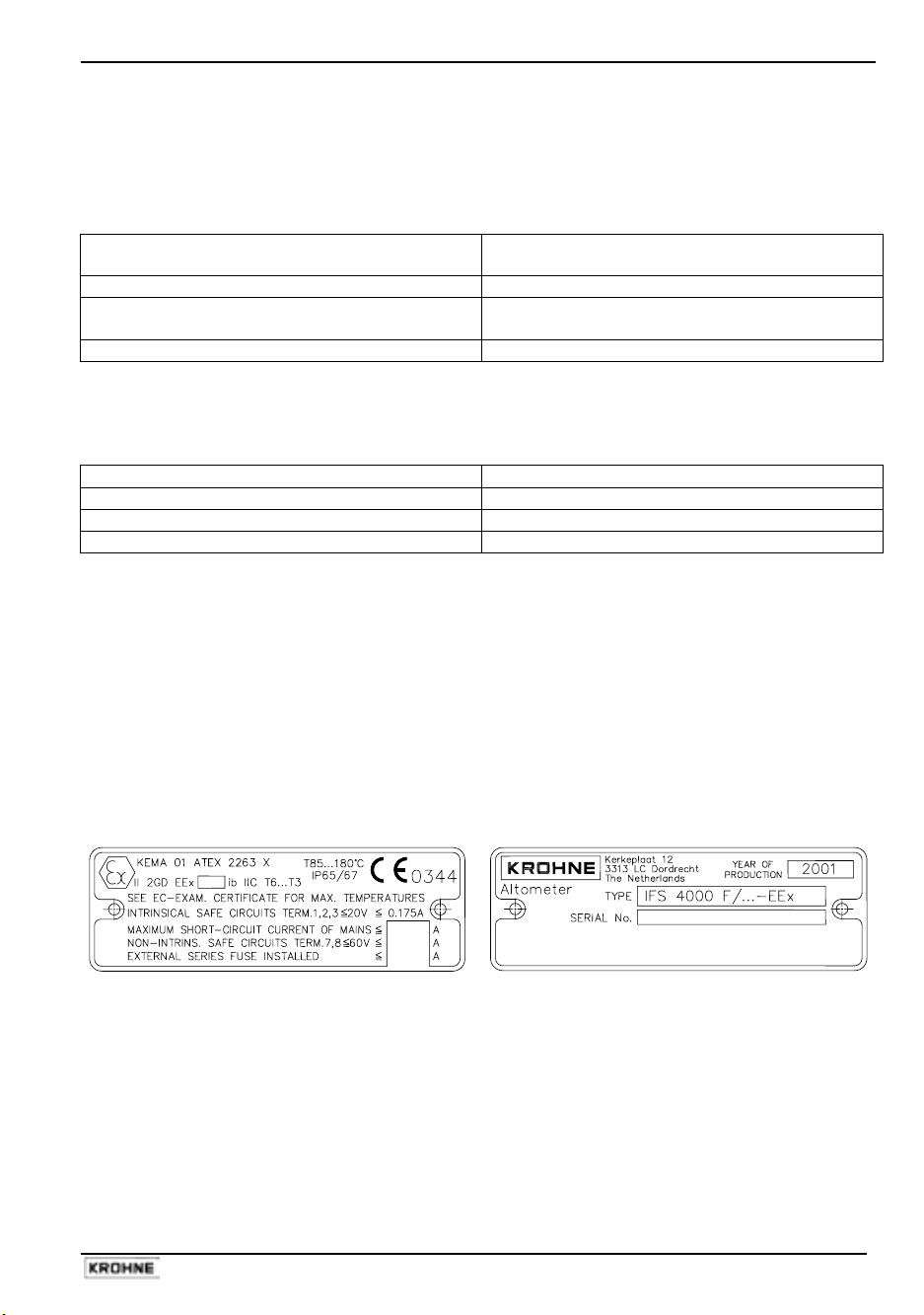
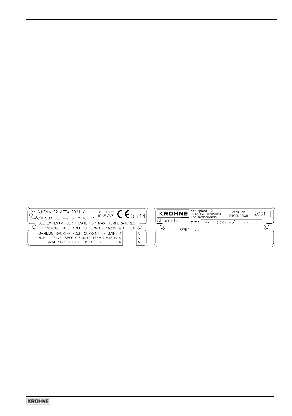
1.1.2 Data plates of ALTOFLUX IFS 4000 F-EEx
Data plate 1 Data plate 2
ALTOFLUX IFS 4000F-EEx, PROFIFLUX IFS 5000F-EEx, VARIFLUX IFS 6000F-EEx 5
Page 6
1.2 General information PROFIFLUX IFS 5000 F-EEx
The PROFIFLUX IFS 5000 F-EEx electromagnetic primary head in remote design (F = field)
complies with the European Directive 94/9 EC (ATEX 100a) and has been approved for hazardous
classified locations of Zone 1 and 2 by the KEMA conform to the European Standards of the EN
500xx series.
They have the following approval number:
KEMA 02 ATEX 2024 X
The IFS 5000 F-EEx primary head with meter sizes DN2.5 up to and including DN15 is designed for
ambient temperatures in the range of -40°C to +60°C. The meter sizes DN25 up to DN100 inclusive
are designed for ambient temperatures ranging from -20°C to +60°C.
The IFS 5000 F-EEx primary head in remote design can be installed in environments that are
classified as Zone 1 or Zone 2 hazardous locations. The maximum permissible process liquid
temperature is dependent on the maximum ambient temperature (Ta) that can occur in that
environment too.
For installation of the IFS 5000 F-EEx primary head please conform to the below listed temperature
classification table. The first column lists the temperature classes for gases and the second one the
rating for dusts.
The table below applies for all meter sizes D2.5 up to and including DN100.
Temperature classification
Temperature
class
T6
T5
T4
T3
Use heat-resistant cables above
The IFS 5000 F-EEx primary head in remote design is connected to a signal converter, e.g. IFC 090
F/…-EEx, which is also approved according to the European Directive 94/9 EC (ATEX 100a). The
signal converter is installed on a distance from the IFS 5000 F-EEx primary head and connected via
a field coil cable, an electrode cable and a bonding wire.
The IFS 5000 F-EEx is marked with the following EEx-code:
II 2GD EEx me ib IIC T6…T3
Also see the EC-type examination certificate in Section 5 of these additional instructions.
Max. surface
temperature
T 80°C 65°C 65°C 65°C
T 95°C 85°C 85°C 80°C
T130°C 125°C 125°C 120°C
T180°C 180°C 165°C 145°C
Maximum process liquid temperature
Ta ≤ 40 °C Ta ≤ 50 °C Ta ≤ 60 °C
165°C 130°C 100°C
6 ALTOFLUX IFS 4000F-EEx, PROFIFLUX IFS 5000F-EEx, VARIFLUX IFS 6000F-EEx
Page 7
1.2.1 Mechanical construction
The IFS 5000 F-EEx primary head is the measuring unit of the flowmetering system (see block
diagram in section 1.4). It contains two field coils and two electrodes in type of protection intrinsic
safety category "ib" according to EN 50020. The type of protection of the field coils is Encapsulation
"m" according to EN 50028 and Increased Safety "e" according to EN 50019.
The electrode circuits are wired by separate shielded cables and marked by the color of the outer
insulation sheath of the cable (white and purple). The intrinsical safe "EEx ib" electrode circuits inside
the IFS 5000 F-EEx primary head have the following maximum values (entity parameters):
Maximum input voltage U
Maximum input current I
Maximum internal capacitance C
Maximum internal inductance L
max
max
i
i
= 20 V
= 170 mA
= 0
= 0
The two field coils inside the primary head are connected in series and have a maximum resistance
of approximately 60 Ω per coil with a wire diameter of at least 0.25 mm and insulation class H (T
max
≥
180°C) according to IEC 85. The field coils are supplied with a square-wave signal with a voltage of ±
40 V and a nominal current of 125 mA. The coil circuit is protected by two 160 mA series fuses,
which are installed inside the associated signal converter unit (e.g. IFC 090 F/…-EEx).
1.2.2 Data plates of PROFIFLUX IFS 5000 F-EEx
Data plate 1 Data plate 2
ALTOFLUX IFS 4000F-EEx, PROFIFLUX IFS 5000F-EEx, VARIFLUX IFS 6000F-EEx 7
Page 8
1.3 General information VARIFLUX IFS 6000 F-EEx
The VARIFLUX IFS 6000 F-EEx electromagnetic primary head in remote design (F = field) complies
with the European Directive 94/9 EC (ATEX 100a) and has been approved for hazardous classified
locations of Zone 1 and 2 by the KEMA conform to the European Standards of the EN 500xx series.
They have the following approval number:
KEMA 02 ATEX 2038 X
The IFS 6000 F-EEx primary head is designed for ambient temperatures in the range of -40°C up to
+60°C inclusive. The IFS 6000 F-EEx primary head in remote design is connected to a associated
signal converter, e.g. IFC 090 F/…-EEx, which is also approved in accordance with the European
Directive 94/9 EC (ATEX 100a). The signal converter is installed on a distance from the IFS 6000 FEEx primary head and connected via a field coil cable, an electrode cable and a bonding wire.
The IFS 6000 F-EEx primary head in remote design can be installed in environments that are
classified as Zone 1 or Zone 2 hazardous locations. The maximum permissible process liquid
temperature is dependent on the maximum ambient temperature (Ta) that can occur in that
environment too.
For installation of the IFS 6000 F-EEx primary head please conform to the below listed temperature
classification table. The first column lists the temperature classes for gases and the second one the
rating for dusts.
Temperature classification
Temperature
class
T6
T5
T4
T3
Use heat-resistant cables above -
The IFS 6000 F-EEx is marked with one of the following EEx-codes, which depends on the meter
size range (see table below).
Marking IFS 6000 F-EEx code
Meter size EEx-code
DN2.5…DN15 II 2GD EEx me ib IIC T6…T3
DN25…DN80 II 2GD EEx de ib IIC T6…T3
Also see the EC-type examination certificate in section 5 of these additional instructions.
Max. surface
temperature
T 80°C 70°C 70°C 70°C
T 95°C 85°C 85°C 85°C
T130°C 120°C 120°C 120°C
T190°C 180°C 180°C 165°C
Maximum process liquid temperature
Ta ≤ 40 °C Ta ≤ 50 °C Ta ≤ 60 °C
160°C 115°C
8 ALTOFLUX IFS 4000F-EEx, PROFIFLUX IFS 5000F-EEx, VARIFLUX IFS 6000F-EEx
Page 9
1.3.1 Mechanical construction
The IFS 6000 F-EEx primary head is the measuring unit of the flowmetering system (see block
diagram in section 1.4). It contains two field coils and two electrodes in type of protection intrinsic
safety category "ib" according to EN 50020. The type of protection of the field coils depends on the
meter size:
DN2.5…DN15 Encapsulation “m” according to EN 50028 and
Increased safety “e” according to EN 50019
DN25…DN150 Flameproof enclosure “d” according to EN 50018
The electrode circuits are wired by separate shielded cables and marked by the sheath color (white
and purple). The intrinsical safe "EEx ib" electrode circuits inside the IFS 6000 F-EEx primary head
have the following maximum values (entity parameters):
Maximum input voltage U
Maximum input current I
Maximum internal capacitance C
Maximum internal inductance L
max
max
i
i
= 20 V
= 170 mA
= 0
= 0
The two field coils inside the primary head are connected in series and have a maximum resistance
of 85 Ω per coil with a wire diameter of at least 0.25 mm and insulation class H (T
≥ 180°C)
max
according to IEC 85. The field coils are supplied with a square-wave signal with a voltage of ± 40 V
and a nominal current of 125 mA. The coil circuit is protected by two 160 mA series fuses, which are
installed inside the associated signal converter unit (e.g. IFC 090 F/…-EEx).
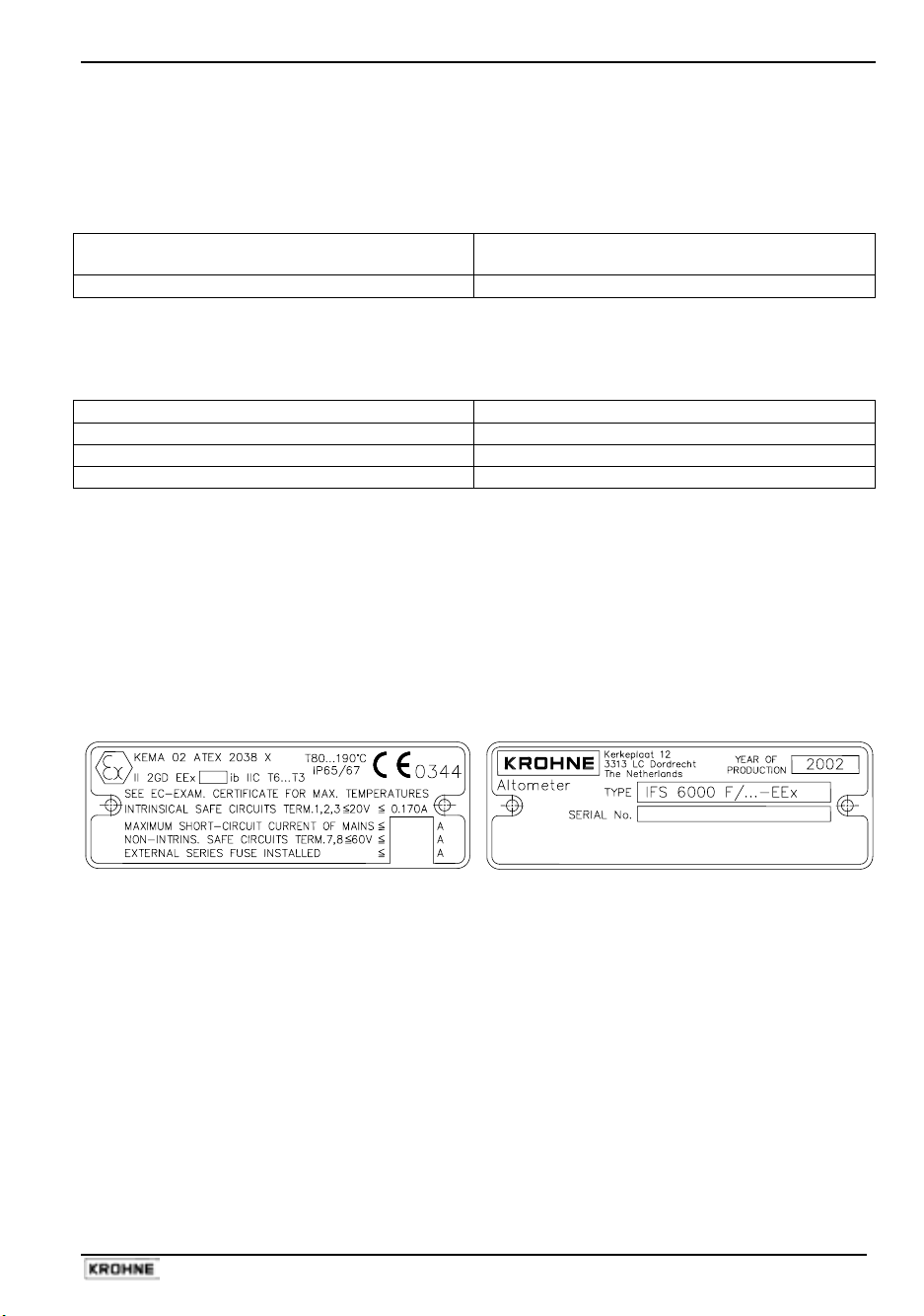
1.3.2 Data plates of VARIFLUX IFS 6000 F-EEx
Data plate 1 Data plate 2
ALTOFLUX IFS 4000F-EEx, PROFIFLUX IFS 5000F-EEx, VARIFLUX IFS 6000F-EEx 9
Page 10

1.4 Block diagram
Flowmetering systems designed for use in hazardous areas consist of the following components
resp. instruments.
Block diagram of flowmetering system with IFS x000 F- EEx
Hazardous area
Hazardous area
or safe area
Current output
“EEx e”
7
S
E
E
M
"EEx e"
"EEx ib"
8
2,3
1
F
F
Frequency output
“EEx e”
B
1
2
3
Equipotential bonding
The block diagram above shows the principle of a flowmetering system with IFS x000 F-EEx
primary head, that is suitable for hazardous locations. An explanation of the several shown items
follows:
1. IFS x000 F-EEx primary head.
2. ZD-EEx intermediate junction box. This junction box is used for certain process liquid
temperatures that result in higher temperatures at the cable entries resp. branching point of
the connecting cable(s) than that is allowed for normal cables. The intermediate junction
box is used to keep the heat-resistant cabling as short as possible (max. 5 m), because of
the higher costs.
3. Signal converter unit (e.g. IFC 090 F/…-EEx). The signal converter unit contains the
electronics that drives the primary head. It can be located in a hazardous area, in which
case the IFC 090 F/…-EEx with flameproof housing is used. When installed in a safe (nonhazardous) area, alternatively to this version the standard non-EEx version can be used. The
standard version is namely also provided with a safety barrier to drive the "EEx ib"
electrodes of the primary head.
Remaining items:
M
E
S
F
B
Measuring tube
Electrode
Magnetic field coil
Field circuit fuse (installed in associated signal converter unit).
Safety barrier with intrinsically safe "ib" outputs.
10 ALTOFLUX IFS 4000F-EEx, PROFIFLUX IFS 5000F-EEx, VARIFLUX IFS 6000F-EEx
Page 11

2 Electrical connection
2.1 Primary fuse connection (only for IFS 5000 F-EEx and IFS 6000 F-EEx)
For all meter sizes (DN2.5 up to and including DN100 in case of IFS 5000 F-EEx, DN2.5 up to and
including DN15 in case of IFS 6000 F-EEx) which also have type of protection Encapsulation "m"
according to EN 50028, the associated signal converter may only be connected to a mains supply
with a prospective short-circuit current of maximum 1500 A for the 100…230 Vac mains supplies
or 300 A for 24 Vac/dc mains supplies.
2.2 Fuse protection of field coil circuit
The field coil circuit is protected against over-current by two fuses of type Wickmann TR5 with a
nominal rating of T160mA. These fuses are soldered into the amplifier printed circuit board of the
electronics unit of the associated signal converter (e.g. IFC 090 F/…-EEx).
2.3 Equipotential bonding system
The IFS x000 F-EEx electromagnetic primary head must always be incorporated into the
equipotential bonding system. Therefore the bonding conductor with a cross-sectional area of at
least 4 mm
to the connecting flange between primary head's housing and junction box.
The U-clamp terminal is made of nickel-plated brass or stainless steel to protect it against corrosion.
Make sure that the core of the bonding wire is properly mounted under the U-clamp and that the
screw is tightly fixed.
2
(i.e. AWG 10) must be connected to the external U-clamp terminal M5 that is mounted
2.4 Intermediate junction box ZD-EEx
For safety reasons, standard cables with a rubber or thermoplastic insulation sheath may only be
used up to a continuous operating temperature of 70°C at the cable entry and 80°C at the branching
point of the connecting cables. In case that the temperature at the above mentioned parts exceed
the maximum values, heat-resistant cables must be installed at the IFS x000 F-EEx primary head in
remote design.
Also see the EC-type examination certificate of the primary head.
The table below summarizes the conditions for use of heat-resistant cables for the IFS x000 F-EEx
primary head.
Use of heat-resistant cables
Primary head Meter size Ambient temperature Process liquid temperature
IFS 4000 F-EEx
IFS 5000 F-EEx DN2.5 - 100
IFS 6000 F-EEx DN2.5 - 80
DN25 - 150
≥ DN200 ≤ 40°C
≤ 40°C
≤ 50°C
≤ 60°C
≤ 50°C
≤ 60°C
≤ 40°C
≤ 50°C
≤ 60°C
≤ 40°C
≤ 50°C
≤ 60°C
not required
≥ 155°C
≥ 105°C
not required
≥ 145°C
≥ 110°C
≥ 165°C
≥ 130°C
≥ 100°C
not required
≥ 160°C
≥ 115°C
ALTOFLUX IFS 4000F-EEx, PROFIFLUX IFS 5000F-EEx, VARIFLUX IFS 6000F-EEx 11
Page 12

In case that heat-resistant cables are required, install the intermediate junction box ZD-EEx at a
distance up to 5 m from the IFS x000 F-EEx primary head. Connect the heat-resistant cables
(cables type D and E in next section) between the primary head's junction box and the intermediate
junction box ZD-EEx. The standard cables (types B and C) can be used between signal converter
unit and intermediate junction box. See the second connection diagram for details (section 2.6).
The silicone rubber insulated connecting cable for the magnetic field coils circuit must be protected
against mechanical damages between the primary head and intermediate junction box by a conduit
system with edge protections. Intermediate box ZD-EEx has terminals with type of protection
increased safety "EEx e" according to EN 50019. The intermediate box is incorporated into the
equipotential bonding system of the installation through its external clamp terminal.
2.5 Connecting cables
Notes:
Cable A
Signal cable for current output and binary outputs (pulse and status output). The cable parameters
must be in accordance with the regulations in the EN 60079-14 "Electrical installations in
hazardous locations" or an equivalent national standard.
Cable B
Power supply cable. The cable parameters must be in accordance with the regulations of the EN
60079-14 "Electrical installations in hazardous locations" or an equivalent national standard.
Rated voltage
Examples H07..-., H05..-.
Cross-sectional area of core
• The below described cables are shown in the connection diagrams. See section 2.6.
• In case that heat-resistant cables have to be used - depends on meter size, process
liquid and ambient temperature - the so-called intermediate junction box type ZD-EEx
must be used. See General information in Section 1 for details.
• The maximum length of the connecting cables between the IFS x000 F-EEx primary
head and the associated signal converter is for safety reasons limited at 50 m. A
shorter cable length can be prescribed for measurement technical reasons, see
therefore the standard Installation and Operating Instructions.
≥ 500 V
1.5 to 2.5 mm2
12 ALTOFLUX IFS 4000F-EEx, PROFIFLUX IFS 5000F-EEx, VARIFLUX IFS 6000F-EEx
Page 13

Cable C
Type DS blue
1
Intrinsical safe, with double shielding
2
3
4
5
6
7
8
3 3
7
6
4
1
1 Stranded drain wire,
1st shield, 1.5 mm
2 Insulation
3 Stranded wire, 0.5 mm2
4 Special foil, 1st shield
5 Insulation
6 Mu-metal foil, 2nd shield
7 Stranded drain wire,
2nd shield, 0.5 mm
8 Outer sheath
(flame-retardant)
2
2
Cable constants
(typical values at Ta = 20°C)
C’3/3 60 pF/m (1 kHz)
C’3/4 110 pF/m (1 kHz)
C’4/6 290 pF/m (1 kHz)
L’3/3 0.85 µH/m (1 kHz)
L’3/4 0.60 µH/m (1 kHz)
R’3 37 mΩ/m
R’4+1 12 mΩ/m
Cable D:
Intrinsical safe, with single shielding. Heat-resistant conform to VDE 0165/02.91.
Properties
Continuous service temperature
Test voltage
Capacitance: core/core
core/shield
Inductance: core/core
Cable length
Single-wire-Ø: core/shield
Cross-sectional area of core
≥ 120°C
≥ 500 V
≤ 200 pF/m
≤ 200 pF/m
≤ 1µH/m
≤ 5 m
≥ 0.1 mm
0.5 to 1.5 mm
2
Sheath light-blue or in other way color-coded as
intrinsical safe, flame-retardant.
Example Silicone rubber insulated, shielded control cable.
Cable E:
Non-intrinsical safe, 2-core without shielding. Heat-resistant conform to VDE 0165/02.91.
Properties
Continuous service temperature
Test voltage
Cross-sectional area of core 1.5 mm
≥ 120°C
≥ 500 V
2
Bonding conductor:
Cross-sectional area Max. 4 mm
2
ALTOFLUX IFS 4000F-EEx, PROFIFLUX IFS 5000F-EEx, VARIFLUX IFS 6000F-EEx 13
Page 14

2.6 Connection diagrams
Connection diagram 1: Standard cables
L N PE 100-230 Vac
SIGNAL IN-/OUTPUTS L L FE 24 Vac/dc
B A
B1 B⊥ B2 I+ I L N
BINARY CURREN T MAINS
OUTPUTS OUTPUT SUPPLY
TERMINAL COMPARTMENT
Standard "EEx e" (opti onal "EEx d")
ELECTRONICS COMPARTMENT (always "EEx d")
Intrinsical safe ("ib") Increased safe ("e")
electr ode circuit s field coil ci rcuit s
(No. "3", "2", "1") (No. "7", "8")
(OPTIONAL)
2
4 mm
≥
3 2 1 7 8
3 2 1 7 8
EQUIPOTENTIAL BONDING CONDUCTOR
2x fuse
160mA
Coil
PE
FE
Flam epro of (E Ex d) c able
feed-t hrough LC-2/EEx
B C
Signal Converter
IFC 090 F/…-EEx
Flam epro of (E Ex d)
terminal feed-through
Hazardous locations
of Zone 1 and 2
Flow tube
E
Electrode c ables - whi te/pink
Coil
(PTFE i nsulated shiel ded copper)
IFS x000 F-EEx
E
E = electrode
Field coil wires - gre en/blue
(PTFE insul ated copper)
Primary Head
14 ALTOFLUX IFS 4000F-EEx, PROFIFLUX IFS 5000F-EEx, VARIFLUX IFS 6000F-EEx
Page 15

Connection diagram 2: Use of heat-resistant cables
Signal Converter
IFC 090 F/…-EEx
ELECTRONICS COMPARTMENT (always "EEx d")
Intrinsi cal safe ("i b") Inc reased safe (" e")
electrode ci rcuits field coi l circui ts
(No. "3", "2", "1") (No. "7", "8")
2x fuse
160mA
Flameproof (EEx d) c able
feed-thr ough LC-2/EEx
3 2 1 7 8
BC
Hazardous locations
of Zone 1 and 2
3 2 1 7 8
ZD-EEx
intermediate
(OPTIONAL)
2
4 mm
≥
junction box
ED
3 2 1 7 8
Coil
EQUIPOTENTI AL BONDING CONDUCTOR
Flow tube
E
(PTFE insulated s hielded copper)
Coil
IFS x000 F-EEx
Primary Head type
Electrode cabl es - white/pink
ALTOFLUX IFS 4000F-EEx, PROFIFLUX IFS 5000F-EEx, VARIFLUX IFS 6000F-EEx 15
E
E = electrode
Field coil wires - green/blue
(PTFE insulat ed copper)
Page 16

3 Maintenance
The IFS x000 F-EEx primary head is maintenance free with regard to the flowmetering properties.
For IFS 4000 F-EEx it is recommended to check the flameproof enclosure of meter sizes DN25 up
to and including DN150, within the scope of the periodical inspections, which are required for
electrical apparatus that are installed and used in hazardous classified locations.
Regarding the IFS 5000 F-EEx no special inspections are required for this electrical apparatus,
even within the scope of the periodical inspections.
For IFS 6000 F-EEx it is recommended to check the flameproof enclosure of meter sizes DN25 up
to and including DN80, within the scope of the periodical inspections, which are required for
electrical apparatus that are installed and used in hazardous classified locations.
16 ALTOFLUX IFS 4000F-EEx, PROFIFLUX IFS 5000F-EEx, VARIFLUX IFS 6000F-EEx
Page 17

4 Declarations of conformity
ALTOFLUX IFS 4000F-EEx, PROFIFLUX IFS 5000F-EEx, VARIFLUX IFS 6000F-EEx 17
Page 18

5 EC-type examination certificates
5.1 ALTOFLUX IFS 4000 F-EEx certificate
18 ALTOFLUX IFS 4000F-EEx, PROFIFLUX IFS 5000F-EEx, VARIFLUX IFS 6000F-EEx
Page 19

ALTOFLUX IFS 4000F-EEx, PROFIFLUX IFS 5000F-EEx, VARIFLUX IFS 6000F-EEx 19
Page 20

20 ALTOFLUX IFS 4000F-EEx, PROFIFLUX IFS 5000F-EEx, VARIFLUX IFS 6000F-EEx
Page 21

ALTOFLUX IFS 4000F-EEx, PROFIFLUX IFS 5000F-EEx, VARIFLUX IFS 6000F-EEx 21
Page 22

22 ALTOFLUX IFS 4000F-EEx, PROFIFLUX IFS 5000F-EEx, VARIFLUX IFS 6000F-EEx
Page 23

ALTOFLUX IFS 4000F-EEx, PROFIFLUX IFS 5000F-EEx, VARIFLUX IFS 6000F-EEx 23
Page 24

5.2 PROFIFLUX IFS 5000 F-EEx certificate
24 ALTOFLUX IFS 4000F-EEx, PROFIFLUX IFS 5000F-EEx, VARIFLUX IFS 6000F-EEx
Page 25

ALTOFLUX IFS 4000F-EEx, PROFIFLUX IFS 5000F-EEx, VARIFLUX IFS 6000F-EEx 25
Page 26

26 ALTOFLUX IFS 4000F-EEx, PROFIFLUX IFS 5000F-EEx, VARIFLUX IFS 6000F-EEx
Page 27

5.3 VARIFLUX IFS 6000 F-EEx certificate
ALTOFLUX IFS 4000F-EEx, PROFIFLUX IFS 5000F-EEx, VARIFLUX IFS 6000F-EEx 27
Page 28

28 ALTOFLUX IFS 4000F-EEx, PROFIFLUX IFS 5000F-EEx, VARIFLUX IFS 6000F-EEx
Page 29

ALTOFLUX IFS 4000F-EEx, PROFIFLUX IFS 5000F-EEx, VARIFLUX IFS 6000F-EEx 29
Page 30

Australia
KROHNE Australia Pty Ltd.
Unit 19 No.9, Hudson Ave.
Castle Hill 2154, NSW
TEL.: +61(0)2-98948711
FAX: +61(0)2-98994855
e-mail: krohne@krohne.com.au
Austria
KROHNE Austria Ges.m.b.H.
Modecenterstraße 14
A-1030 Wien
TEL.: +43(0)1/203 45 32
FAX: +43(0)1/203 47 78
e-mail: info@krohne.at
Belgium
KROHNE Belgium N.V.
Brusselstraat 320
B-1702 Groot Bijgaarden
TEL.: +32(0)2-4 66 00 10
FAX: +32(0)2-4 66 08 00
e-mail: krohne@krohne.be
Brazil
KROHNE Conaut
Controles Automaticos Ltda.
Estrada Das Águas Espraiadas, 230 C.P. 56
06835 - 080 EMBU - SP
TEL.: +55(0)11-4785-2700
FAX: +55(0)11-4785-2768
e-mail: conaut@conaut.com.br
China
KROHNE Measurement Instruments Co. Ltd.
Room 7E, Yi Dian Mansion
746 Zhao Jia Bang Road
Shanghai 200030
TEL.: +86(0)21-64677163
FAX: +86(0)21-64677166
Cellphone: +86(0)139 1885890
e-mail: info@krohne-asia.com
CIS
Kanex KROHNE Engineering AG
Business-Centre Planeta, Office 403
ul. Marxistskaja 3
109147 Moscow/Russia
TEL.: +7(0)095-9117165
FAX: +7(0)095-9117231
e-mail: krohne@dol.ru
Czech Republic
KROHNE CZ, spol. s r.o.
Sobe˘s˘ická 156
CZ-63800 Brno
TEL.: +420 545 532 111
FAX: +420 545 220 093
e-mail: brno@krohne.cz
Algeria
Argentina
Bulgaria
Camaroon
Canada
Chile
Columbia
Croatia
Denmark
Ecuador
Egypt
Finland
French Antilles
Greece
Guinea
Hong Kong
Hungary
Indonesia
Ivory Coast
Iran
Ireland
Israel
Japan
Jordan
Kuwait
Marocco
Mauritius
Mexico
New Zealand
Pakistan
Poland
Portugal
Saudi Arabia
Senegal
Singapore
Slovakia
Slovenia
Sweden
Tai wan
Thailand
Turkey
Tunesia
Venezuela
Yugoslavia
France
KROHNE S.A.S.
Usine des Ors
BP 98
F-26 103 Romans Cedex
TEL.: +33(0)4-75 05 44 00
FAX: +33(0)4-75 05 00 48
e-mail: info@krohne.fr
Germany
KROHNE Messtechnik
GmbH & Co. KG
Ludwig-Krohne-Straße
D-47058 Duisburg
TEL.: +49(0)203-301-0
FAX: +49(0)203-301 389
e-mail: krohne@krohne.de
India
KROHNE Marshall Ltd.
A-34/35, M.I.D.C.
Industrial Area, H-Block,
Pimpri Poona 411018
TEL.: +91(0)20-744 20 20
FAX: +91(0)20 -744 20 40
e-mail: pcu@vsnl.net
Italy
KROHNE Italia Srl.
Via V. Monti 75
I-20145 Milano
TEL.: +39(0)2-4 30 06 61
FAX: +39(0)2-43 00 66 66
e-mail: krohne@krohne.it
Korea
Hankuk KROHNE
2 F, 599-1
Banghwa-2-Dong
Kangseo-Ku
Seoul
TEL.: +82(0)2665-85 23-4
FAX: +82(0)2665-85 25
e-mail: flowtech@unitel.co.kr
Netherlands
KROHNE Altometer
Kerkeplaat 12
NL-3313 LC Dordrecht
TEL.: +31(0)78-6306300
FAX: +31(0)78-6306390
e-mail: postmaster@krohne-altometer.nl
KROHNE Nederland B.V.
Kerkeplaat 12
NL-3313 LC Dordrecht
TEL.: +31(0)78-6306200
FAX: +31(0)78-6306405
Service Direkt: +31(0)78-6306222
e-mail: info@krohne.nl
Norway
Krohne Instrumentation A.S.
Ekholtveien 114
NO-1526 Moss
P. O. Box 2178, NO-1521 Moss
TEL.: +47(0)69-264860
FAX: +47(0)69-267333
e-mail: postmaster@krohne.no
Internet: www.krohne.no
South Africa
KROHNE Pty.Ltd.
163 New Road
Halfway House Ext. 13
Midrand
TEL.: +27(0)11-315-2685
FAX: +27(0)11-805-0531
e-mail: midrand@krohne.co.za
Spain
I.I. KROHNE Iberia, S.r.L.
Poligono Industrial Nilo
Calle Brasil, n°. 5
E-28806 Alcalá de Henares-Madrid
TEL.: +34(0)91-8 83 21 52
FAX: +34(0)91-8 83 48 54
e-mail: krohne@krohne.es
Switzerland
KROHNE AG
Uferstr. 90
CH-4019 Basel
TEL.: +41(0)61-638 30 30
FAX: +41(0)61-638 30 40
e-mail: info@krohne.ch
United Kingdom
KROHNE Ltd.
Rutherford Drive
Park Farm Industrial Estate
Wellingborough,
Northants NN8 6AE, UK
TEL.: +44(0)19 33-408 500
FAX: +44(0)19 33-408 501
e-mail: info@krohne.co.uk
USA
KROHNE Inc.
7 Dearborn Road
Peabody, MA 01960
TEL.: +1-978 535-6060
FAX: +1-978 535 -1720
e-mail: info@krohne.com
Overseas Representatives
Other Countries:
KROHNE Messtechnik
GmbH & Co. KG
Ludwig-Krohne-Str.
D-47058 Duisburg
TEL.: +49(0)203-301 309
FAX: +49(0)203-301 389
e-mail: export@krohne.de
Subject to change without notice
 Loading...