

Page 1
Technical Datasheet
Technical Datasheet
IFC 100
IFC 100
IFC 100IFC 100
Technical DatasheetTechnical Datasheet
Signal converter for electromagnetic flowmeters
•
Extended accuracy option
•
Diagnostics of device and application
•
Certified for use in hazardous areas
The documentation is only complete when used in combination with the relevant
documentation for the flow sensor.
© KROHNE 03/2018 - 4000040506 - TD IFC 100 R06 en
Page 2

CONTENTS
IFC 100
1 Product features 3
1.1 The all-round solution...................................................................................................... 3
1.2 Options and variants......................................................................................................... 5
1.3 Signal converter/flow sensor combination possibilities ................................................. 7
1.4 Measuring principle.......................................................................................................... 7
2 Technical data 8
2.1 Technical data................................................................................................................... 8
2.2 Dimensions and weight .................................................................................................. 15
2.2.1 Housing ................................................................................................................................. 15
2.2.2 Mounting plate of wall-mounted version, aluminium housing............................................ 19
2.2.3 Mounting plate of wall-mounted version, stainless steel housing...................................... 20
2.3 Flow tables ..................................................................................................................... 21
2.4 Measuring accuracy ....................................................................................................... 23
3 Installation 24
3.1 Intended use ................................................................................................................... 24
3.2 Installation specifications .............................................................................................. 24
3.3 Mounting of the compact version................................................................................... 24
3.4 Mounting the wall-mounted housing, remote version .................................................. 25
3.4.1 Wall mounting....................................................................................................................... 25
4 Electrical connections 28
4.1 Important notes on electrical connection...................................................................... 28
4.2 Preparing the signal and field current cables ............................................................... 28
4.2.1 Signal cable A (type DS 300), construction........................................................................... 28
4.2.2 Length of signal cable A........................................................................................................ 29
4.2.3 Connection diagram for signal and field current cable ....................................................... 30
4.3 Connecting the power supply......................................................................................... 31
4.4 Overview of outputs ........................................................................................................33
4.4.1 Description of the CG number .............................................................................................. 33
4.4.2 Fixed, non-alterable output versions ................................................................................... 33
4.5 Laying electrical cables correctly .................................................................................. 34
5 Notes 35
2
www.krohne.com 03/2018 - 4000040506 - TD IFC 100 R06 en
Page 3

IFC 100
1.1 The all-round solution
The IFC 100
IFC 100 electromagnetic signal converter combines an attractive price with a wide range of
IFC 100IFC 100
features and benefits including an excellent measuring accuracy.
The signal converter is compatible with almost any flow sensor in the OPTIFLUX and
WATERFLUX range.
The signal converter supplies the current required by two field coils to generate a magnetic field.
It converts the flow proportional signal voltage into digital values and filters out electrical noise
and interference signals. From the filtered signal, the flow velocity, the volume flow and the
mass flow are calculated.
The IFC 100
IFC 100 signal converter provides a large variety of flowmeter and process diagnostic
IFC 100IFC 100
functions guaranteeing reliable measurements. Detection of deposits or coating on the
electrodes, temperature and conductivity changes in the medium, gas bubbles or solids, and an
empty pipe are good examples of process diagnostics functions.
The flow velocity and volume can be read from the display or in analogue form via the current
output (4...20 mA) as well as by frequency, pulse and status outputs. Measuring values and
diagnostic information can be transmitted via the HART
PRODUCT FEATURES
®
interface.
1
(signal converter in wall-mounted aluminium housing)
1 Large graphic display with backlit
2 Push buttons (4) for operator control without opening the housing
3 Intuitive navigation and quick menu setup
www.krohne.com03/2018 - 4000040506 - TD IFC 100 R06 en
3
Page 4

1
PRODUCT FEATURES
Highlights
• For operation with a wide range of OPTIFLUX and WATERFLUX flow sensors
• For flow sensors over a diameter range from DN2.5 up to DN1200
• Housing in aluminium with a polyester topcoat or in stainless steel (option)
• Tropicalized electronics to protect it from humidity (option)
• Available outputs: 4...20 mA current output, pulse/frequency output and status output/limit
switch
®
• HART
• Power supply via 100…230 VAC (standard) or 24 VDC or 24 VAC/DC (optional)
• Clearly readable values due to angle of the signal converter housing which prevents dirt and
dust on the display
• Extended calibration option for higher measuring accuracy down to 0.2% of the measuring
value
• Excellent price/performance ratio
as standard
Industries
• Machinery
• Water & Wastewater
• HVAC, energy management
• Chemical
• Food and Beverages
• Metals and Mining
IFC 100
Applications
• Flow in electrically conductive mediums with a minimum conductivity of 5 µS/cm
• Water flow measurements in a wide range of industries
• Water based chemicals
• Sludge and slurries
• Sanitary applications and (HoCIP, SIP) liquid food & beverages
4
www.krohne.com 03/2018 - 4000040506 - TD IFC 100 R06 en
Page 5

IFC 100
1.2 Options and variants
Compact or remote wall-mounted housing
(signal converter in wall-mounted
aluminium housing)
PRODUCT FEATURES
For an optimal reading of the display, the compact
variant comes in a 0° and a 45° version.
The signal converter can be rotated in 90°
increments to suit different installation positions.
The compact 0° version is designed for flowmeters
in vertical pipelines, the compact 45° version for
horizontal installations.
The wall mounted signal converter can be installed
remotely for locations where the sensor is difficult to
access, or ambient temperature conditions or
vibrations prevent a compact variant.
1
Variant for use in hazardous areas
(Compact version as 0° version)
The IFC 100 signal converter is available in a variant
suitable for hazardous areas with approvals to ATEX,
IECEx, FM, CSA and NEPSI.
www.krohne.com03/2018 - 4000040506 - TD IFC 100 R06 en
5
Page 6

1
PRODUCT FEATURES
Stainless steel housing (option)
(signal converter in wall-mounted
stainless steel housing)
IFC 100
Whereas the standard housing material is
aluminium with a polyester topcoat, the IFC 100
optionally be ordered in a stainless steel housing.
The robust housing is suitable for many applications
in the food and beverage industry.
It is designed for environments where extreme
chemicals or aggressive cleaning are used.
The housing is dual rated to IP67/69 protection
category to resist wash down cleaning and no glass
is used for the display window.
The mounting angle for the compact housing and the
rounded edges in the wall-mount position prevent
dirt and water from building up on the surface.
IFC 100 can
IFC 100IFC 100
Diagnostics of device and application
OPTICHECK tool for on-site verification
The primary focus of a user for a flowmeter is that it
delivers reliable measurements. To achieve this all
our electromagnetic flowmeters are calibrated
before leaving the factory.
In addition, the IFC 100
functions on the flow sensor, signal converter and
process, integrated in the signal converter.
Potential problems including gas bubbles, solids,
electrode corrosion, deposits on electrodes,
conductivity changes, empty pipe can be detected by
the diagnostics features.
The OPTICHECK provides an inline health check of the
device under test by an external tool.
When the tool is connected on site, it gathers measuring
data to ensure that the flowmeter performs within 1% of its
factory calibration.
IFC 100 provides a range diagnostic
IFC 100IFC 100
(Suitcase with OPTICHECK and all cables and
accesssories)
6
The baseline can be historic repair data from the factory or
on-site test results after performing a full verification.
A hard copy of the verification report can be printed for
every flowmeter. The verification data are digitally stored.
Contact us for more information or for an on-site service
visit.
www.krohne.com 03/2018 - 4000040506 - TD IFC 100 R06 en
Page 7
IFC 100
PRODUCT FEATURES
1.3 Signal converter/flow sensor combination possibilities
Flow sensor Flow sensor + signal converter IFC 100
Compact (0°/45° version) Remote wall-mounted
housing
OPTIFLUX 1000 OPTIFLUX 1100 C OPTIFLUX 1100 W
OPTIFLUX 2000 OPTIFLUX 2100 C OPTIFLUX 2100 W
OPTIFLUX 4000 OPTIFLUX 4100 C OPTIFLUX 4100 W
OPTIFLUX 5000 OPTIFLUX 5100 C OPTIFLUX 5100 W
OPTIFLUX 6000 OPTIFLUX 6100 C OPTIFLUX 6100 W
WATERFLUX 3000 WATERFLUX 3100 C WATERFLUX 3100 W
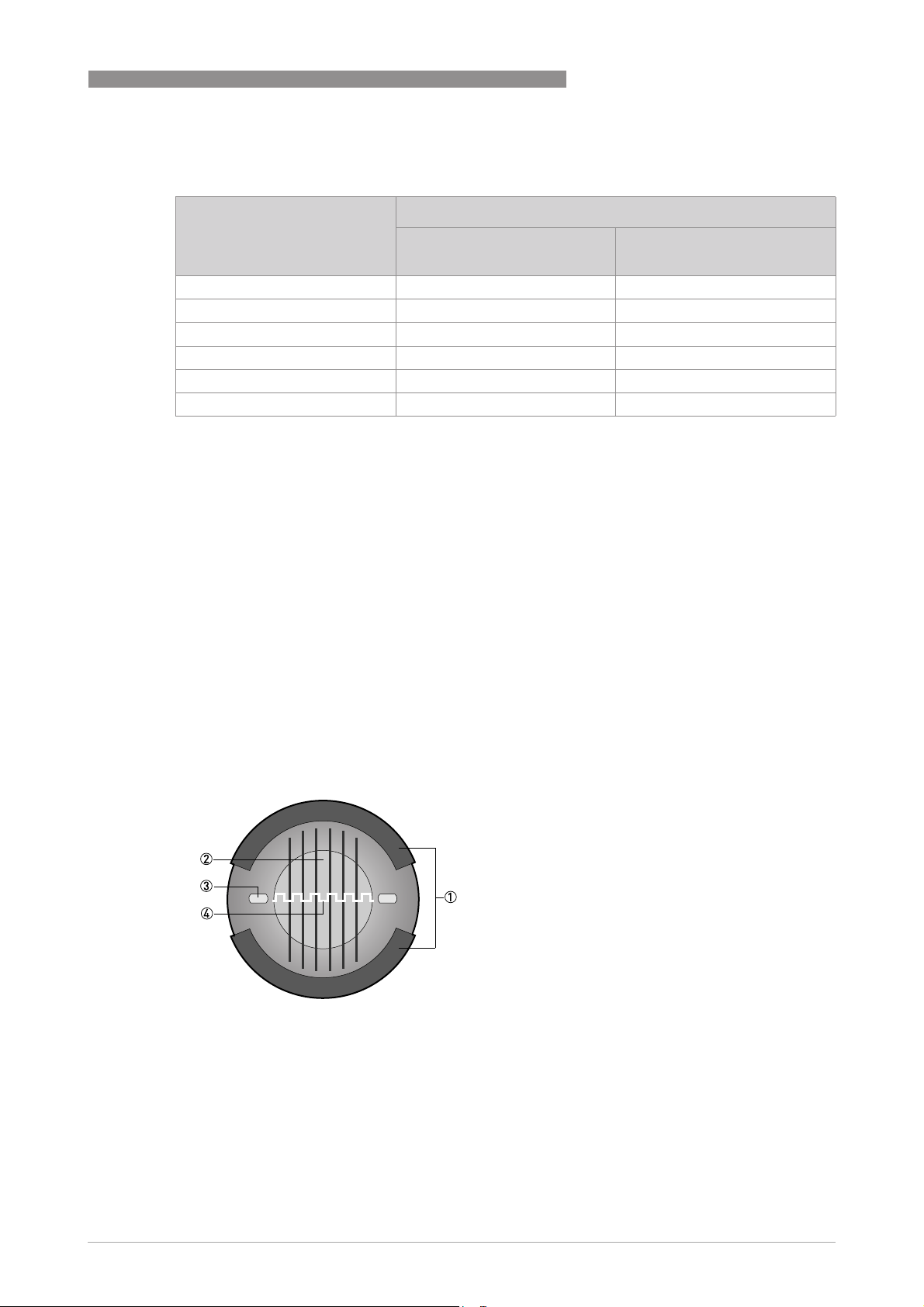
1.4 Measuring principle
An electrically conductive fluid flows inside an electrically insulated pipe through a magnetic
field. This magnetic field is generated by a current, flowing through a pair of field coils.
Inside of the fluid, a voltage U is generated:
U = v * k * B * D
U = v * k * B * D
U = v * k * B * DU = v * k * B * D
1
in which:
v = mean flow velocity
k = factor correcting for geometry
B = magnetic field strength
D = inner diameter of flowmeter
The signal voltage U is picked off by electrodes and is proportional to the mean flow velocity v
and thus the flow rate Q. A signal converter is used to amplify the signal voltage, filter it and
convert it into signals for totalizing, recording and output processing.
Figure 1-1: Measuring principle
1 Field coils
2 Magnetic field
3 Electrodes
4 Induced voltage (proportional to flow velocity)
www.krohne.com03/2018 - 4000040506 - TD IFC 100 R06 en
7
Page 8
2
TECHNICAL DATA
IFC 100
2.1 Technical data
•
The following data is provided for general applications. If you require data that is more
relevant to your specific application, please contact us or your local sales office.
•
Additional information (certificates, special tools, software,...) and complete product
documentation can be downloaded free of charge from the website (Downloadcenter).
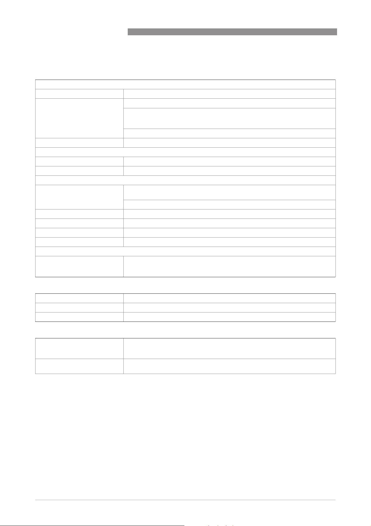
Measuring system
Measuring principle Faraday's law of induction
Application range Continuous measurement of current volume flow, flow velocity, conductivity, mass
Design
Modular construction The measuring system consists of a flow sensor and a signal converter.
Flow sensor
Flow sensor
Flow sensorFlow sensor
OPTIFLUX 1000 DN10...150 / 3/8…6"
OPTIFLUX 2000 DN25...1200 / 1…48"
OPTIFLUX 4000 DN2.5...1200 / 1/10…48"
OPTIFLUX 5000 Flange: DN15...300 / 1/2...12"
OPTIFLUX 6000 DN2.5...150 / 1/10…6"
WATERFLUX 3000 DN25...600 / 1...24"
Signal converter
Signal converter
Signal converterSignal converter
Compact version (C) IFC 100 C (0° & 45° version)
Remote version (W) IFC 100 W
Options
Options
OptionsOptions
Outputs
Counter 2 internal counters with a max. of 10 counter places (e.g. for counting volume
Verification Integrated verification, diagnostic functions: measuring device, empty pipe
Communication interface
flow (at constant density), coil temperature of the flow sensor
Sandwich: DN2.5...100 / 1/10…4"
With the exception of the OPTIFLUX 1000 and WATERFLUX 3000 all flow sensors are
also available in an Ex version.
With the exception of the OPTIFLUX 1000 and WATERFLUX 3000 all flow sensors are
also available in an Ex version.
Current output (including HART®), pulse output, frequency output, status output
and/or limit switch
and/or mass units)
detection, stabilisation
HART® as standard
8
www.krohne.com 03/2018 - 4000040506 - TD IFC 100 R06 en
Page 9
IFC 100
Display and user interface
Display and user interface
Display and user interfaceDisplay and user interface
Graphic display LC display, backlit white.
Size: 128 x 64 pixels, corresponds to 59 x 31 mm = 2.32" x 1.22"
Ambient temperatures below -25°C/ -13°F may affect the readability of the display.
Operating elements 4 push buttons for operator control of the signal converter without opening the
Remote control
Display functions
Display functions
Display functionsDisplay functions
Operating menu Setting the parameters using 2 measuring pages, 1 status page, 1 graphic page
Language of display texts (as
language package)
Units Metric, British and US units selectable as required from lists for volume/mass flow
housing.
PACTwareTM (including Device Type Manager (DTM))
HART® Hand Held Communicator from Emerson Process
AMS® from Emerson Process
PDM® from Siemens
All DTMs and drivers are available free of charge from the manufacturer's website.
(measured values and graphics are freely adjustable)
Standard: English, French, German, Dutch, Portuguese, Swedish, Spanish, Italian
Eastern Europe: English, Slovenian, Czech, Hungarian
Northern Europe: English, Danish, Polish, Finnish, Norwegian
Southern Europe: English, Turkish
China: English, German, Chinese
Russia: English, German, Russian
and counting, flow velocity, electrical conductivity, temperature
TECHNICAL DATA
2
Measuring accuracy
Max. measuring accuracy Standard:
Repeatability ±0.1%
Standard:
Standard:Standard:
±0.3% of the measured value ± 1 mm/s; depending on the flow sensor
Option (optimised accuracy with extended calibration):
Option (optimised accuracy with extended calibration):
Option (optimised accuracy with extended calibration):Option (optimised accuracy with extended calibration):
±0.2% of the measured value ± 1.5 mm/s; depending on the flow sensor
For detailed information and accuracy curves refer to
23.
Special calibrations are available on request.
Current output electronics: ±10 µA; ±100 ppm/°C (typically: ±30 ppm/°C)
Measuring accuracy
on page
www.krohne.com03/2018 - 4000040506 - TD IFC 100 R06 en
9
Page 10
2
TECHNICAL DATA
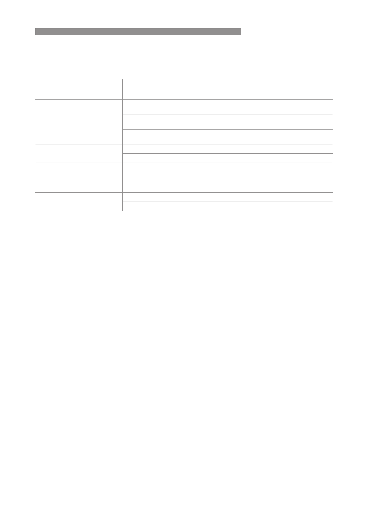
Operating conditions
Temperature
Temperature
TemperatureTemperature
Process temperature Refer to technical data for the flow sensor.
Ambient temperature Depending on the version and combination of outputs.
It is a good idea to protect the signal converter from external heat sources such as
direct sunlight as higher temperatures reduce the life cycle of all electronic
components.
Ambient temperatures below -25°C/ -13°F may affect the readability of the display.
Storage temperature -40…+70°C/ -40…+158°F
Pressure
Pressure
PressurePressure
Medium Refer to technical data for the flow sensor.
Ambient pressure Atmospheric
Chemical properties
Chemical properties
Chemical propertiesChemical properties
Electrical conductivity All media except for water: ≥ 5 µS/cm
State of aggregation Conductive, liquid media
Solid content (volume) ≤ 10% for OPTIFLUX flow sensors
Gas content (volume) ≤ 3% for OPTIFLUX flow sensors
Flow rate For detailed information, refer to chapter "Flow tables".
Other conditions
Other conditions
Other conditionsOther conditions
Ingress protection according to
IEC 60529
(also refer to the technical data for the flow sensor)
Water: ≥ 20 µS/cm
Standard version with aluminium housing: IP66/67 (according to NEMA 4/4X)
Optional version with stainless steel housing: IP69
IFC 100
Installation conditions
Installation For detailed information, refer to chapter "Installation".
Inlet / outlet sections Refer to technical data for the flow sensor.
Dimensions and weight For detailed information refer to chapter "Dimensions and weight".
Materials
Signal converter housing Standard: Aluminium with a polyester topcoat
Option: Stainless steel 1.4404 / AISI 316L
Flow sensor For housing materials, process connections, liners, grounding electrodes and
gaskets, refer to technical data for the flow sensor.
10
www.krohne.com 03/2018 - 4000040506 - TD IFC 100 R06 en
Page 11
IFC 100
TECHNICAL DATA
Electrical connection
General Electrical connection is carried out in conformity with the VDE 0100 directive
Power supply 100…230 VAC (-15% / +10%), 50/60 Hz; non-Ex: standard; Ex: optional
Power consumption AC: 7 VA
Signal cable Only necessary for remote versions.
Cable entries Standard: M20 x 1.5 (8...12 mm)
"Regulations for electrical power installations with line voltages up to 1000 V" or
equivalent national specifications.
240 VAC + 5% is included in the tolerance range.
24 VDC (-55% / +30%); only available as non-Ex version
12 VDC - 10% is included in the tolerance range.
24 VAC/DC (AC: -15% / +10%; DC: -25% / +30%); non-Ex: standard; Ex: optional
12 V is not
not included in the tolerance range.
notnot
DC: 4 W
DS 300 (type A)
DS 300 (type A)
DS 300 (type A)DS 300 (type A)
Max. length: 600 m / 1968 ft (depending on electrical conductivity and flow sensor
version)
Option: 1/2 NPT, PF 1/2
2
www.krohne.com03/2018 - 4000040506 - TD IFC 100 R06 en
11
Page 12

2
TECHNICAL DATA
Outputs
General All outputs are electrically isolated from each other and from all other circuits.
All operating data and output values can be adjusted.
Description of abbreviations U
Current output
Current output
Current outputCurrent output
Output data Volume flow, mass flow, diagnostic value, flow velocity, coil temperature,
Settings
Operating data
Operating data
Operating dataOperating data
Active U
= external voltage; RL = load + resistance;
ext
= terminal voltage; I
U
o
= nominal current
nom
conductivity
Without HART
Without HART
Without HARTWithout HART
®
Q = 0%: 0…20 mA; Q = 100%: 10…21.5 mA
Error identification: 20…22 mA
With HART
With HART
With HARTWith HART
®
Q = 0%: 4…20 mA; Q = 100%: 10…21.5 mA
Error identification: 3…22 mA
=20VDC
int, nom
IFC 100
I ≤ 22 mA
≤ 750 Ω
R
L
HART® at terminals A
Passive U
≤ 32 VDC
ext
I ≤ 22 mA
≥ 2V at I=22mA
U
0
RL≤ (U
ext-U0
)/I
max
HART® at terminals A
®
HART
HART
HARTHART
Description
HART® protocol via active and passive current output
HART® version: V5
Universal Common Practice HART® parameter: completely supported
Load
≥ 230 Ω at HART® test point;
Note maximum load for current output!
Multi-drop mode Yes, current output = 4 mA
Multi-drop address adjustable in operation menu 1…15
Device drivers Available for FC 375/475, AMS, PDM, FDT/DTM
Registration (HART
Yes
Communication Foundation)
12
www.krohne.com 03/2018 - 4000040506 - TD IFC 100 R06 en
Page 13

IFC 100
Pulse output / frequency output
Pulse output / frequency output
Pulse output / frequency outputPulse output / frequency output
TECHNICAL DATA
Output data Pulse output: volume flow, mass flow
Frequency output: volume flow, mass flow, diagnostic value, flow velocity, coil
temperature, conductivity
Function Can be set as a pulse output or frequency output
Pulse rate/frequency 0.25...10000 Hz
Settings Pulses per volume or mass unit or max. frequency for 100% flow
Pulse width: adjustable as automatic, symmetric or fixed (0.05...2000 ms)
Operating data
Operating data
Operating dataOperating data
Passive U
≤ 32 VDC
ext
f
in operating menu set to f
max
max
≤ 100 Hz:
I ≤ 100 mA
2
open:
I ≤ 0.05 mA at U
=32VDC
ext
closed:
U
= 0.2 V at I ≤ 10 mA
0, max
= 2 V at I ≤ 100 mA
U
0, max
f
in operating menu set to 100 Hz < f
max
max
≤10 kHz:
I ≤ 20 mA
open:
I ≤ 0.05 mA at U
=32VDC
ext
closed:
= 1.5 V at I ≤ 1mA
U
0, max
= 2.5 V at I ≤ 10 mA
U
0, max
U
= 5.0 V at I ≤ 20 mA
0, max
Low flow cut off
Low flow cut off
Low flow cut offLow flow cut off
Function Switching point and hysteresis separately adjustable for each output, counter and
the display
Switching point Set in increments of 0.1%.
0…20% (current output, frequency output) or 0...±9.999 m/s (pulse output)
Hysteresis Set in increments of 0.1%.
0…5% (current output, frequency output) or 0…5 m/s (pulse output)
Time constant
Time constant
Time constantTime constant
Function The time constant corresponds to the elapsed time until 67% of the end value has
been reached according to a step function.
Settings Set in increments of 0.1 seconds.
0…100 seconds
www.krohne.com03/2018 - 4000040506 - TD IFC 100 R06 en
13
Page 14

2
TECHNICAL DATA
Status output / limit switch
Status output / limit switch
Status output / limit switchStatus output / limit switch
Function and settings Adjustable as automatic measuring range conversion, display of flow direction,
Operating data
Operating data
Operating dataOperating data
Passive U
counter overflow, error, switching point or empty pipe detection
Valve control with activated dosing function
Status and/or control: ON or OFF
≤ 32 VDC
ext
I ≤ 100 mA
IFC 100
open:
I ≤ 0.05 mA at U
closed:
U
= 0.2 V at I ≤ 10 mA
0, max
= 2 V at I ≤ 100 mA
U
0, max
=32VDC
ext
Approvals and certificates
CE This device fulfils the statutory requirements of the relevant EU directives.
Non-Ex Standard
Hazardous areas
Hazardous areas
Hazardous areasHazardous areas
ATEX Option (only OPTIFLUX 2100 C and OPTIFLUX 4100 C)
IECEx Option (only OPTIFLUX 2100 C and OPTIFLUX 4100 C)
FM/CSA Option (only OPTIFLUX 2100 C and OPTIFLUX 4100 C)
The manufacturer certifies successful testing of the product by applying the CE
mark.
For full information of the EU directives & standards and the approved
certifications, please refer to the EU declaration or the manufacturer website.
Option (only OPTIFLUX 2100 C and OPTIFLUX 4100 C)
Option (only OPTIFLUX 2100 C and OPTIFLUX 4100 C)Option (only OPTIFLUX 2100 C and OPTIFLUX 4100 C)
II 2 G Ex e [ia] mb IIC T4 (DN10...20; DN200...300; DN350...3000)
II 2 G Ex d e [ia] mb IIC T4 (DN25...150)
II 2 G Ex e [ia] mb q T4/T3 (DN25...150; DN200...300)
II 2 D Ex tD A21 IP64 T120°C (all nominal sizes)
Option (only W version)
Option (only W version)
Option (only W version)Option (only W version)
II 2 G Ex e [ia] mb IIC T4
II 2 D Ex tD A21 IP64 T135°C
Option (only OPTIFLUX 2100 C and OPTIFLUX 4100 C)
Option (only OPTIFLUX 2100 C and OPTIFLUX 4100 C)Option (only OPTIFLUX 2100 C and OPTIFLUX 4100 C)
Ex e [ia] mb IIC T4 (DN10...20; DN200...300; DN350...3000)
Ex d e [ia] mb IIC T4 (DN25...150)
Ex tD A21 IP64 T120°C (all nominal sizes)
Option (only W version)
Option (only W version)
Option (only W version)Option (only W version)
Ex e [ia] mb IIC T4
Ex tD A21 IP64 T135°C
Option (only OPTIFLUX 2100 C and OPTIFLUX 4100 C)
Option (only OPTIFLUX 2100 C and OPTIFLUX 4100 C)Option (only OPTIFLUX 2100 C and OPTIFLUX 4100 C)
Class I, Div 2, Group A, B, C and D
Option (only W version)
Option (only W version)
Option (only W version)Option (only W version)
Class I, Div 2, Group A, B, C and D
Ordinary location
14
www.krohne.com 03/2018 - 4000040506 - TD IFC 100 R06 en
Page 15

IFC 100
Other standards and approvals
Other standards and approvals
Other standards and approvalsOther standards and approvals
Electromagnetic compatibility
(EMC)
Shock and vibration resistance IEC 68-2-27, IEC 68-2-64
NAMUR NE 21, NE 43, NE 53
2004/108/EU in conjunction with EN 61326-1 (A1, A2)
2.2 Dimensions and weight
2.2.1 Housing
TECHNICAL DATA
2
Figure 2-1: Dimensions of the wall-mounted version, aluminium housing
a b c d e f g
Wall-mounted
version
Table 2-1: Dimensions and weight in mm and kg
241 161 95.2 257 19.3 39.7 40 1.9
a b c d e f g
Wall-mounted
version
Table 2-2: Dimensions and weight in inch and lb
9.50 6.34 3.75 10.12 0.76 1.56 1.57 4.2
Dimensions [mm] Weight [kg]
Dimensions [inch] Weight [lb]
www.krohne.com03/2018 - 4000040506 - TD IFC 100 R06 en
15
Page 16

2
TECHNICAL DATA
IFC 100
Figure 2-2: Dimensions of wall-mounted and compact 10° version, stainless steel housing
a b c d e f g
Wall-mounted
version
Table 2-3: Dimensions and weight in mm and kg
268 187 110 276 29 53 40 Approx. 3.5
a b c d e f g
Wall-mounted
version
Table 2-4: Dimensions and weight in inch and lb
10.55 7.36 4.33 10.87 1.14 2.09 1.57 Approx. 7.2
The compact 10° version is without mounting plate.
e
g
g
g
f
Dimensions [mm] Weight [kg]
Dimensions [inch] Weight [lb]
16
www.krohne.com 03/2018 - 4000040506 - TD IFC 100 R06 en
Page 17

IFC 100
Figure 2-3: Dimensions of compact 0° version, aluminium housing
1 4 x M 6
Dimensions [mm] Weight [kg]
a b c d e f g h
TECHNICAL DATA
2
0° version 161 40 155 81.5 257 - - Ø72 Std: 1.9
Ex: 2.4
Table 2-5: Dimensions and weight in mm and kg
Dimensions [inch] Weight [lb]
a b c d e f g h
0° version 6.34 1.57 6.1 3.21 10.12 - - Ø2.83 Std: 4.2
Ex: 5.3
Table 2-6: Dimensions and weight in inch and lb
www.krohne.com03/2018 - 4000040506 - TD IFC 100 R06 en
17
Page 18

2
TECHNICAL DATA
Figure 2-4: Dimensions of compact 45° version, aluminium housing
1 4 x M 6
a b c d e f g h
IFC 100
Dimensions [mm] Weight [kg]
45° version 161 40 155 184 27.4 45° 186 Ø72 Std: 2.1
Ex: 2.6
Table 2-7: Dimensions and weight in mm and kg
Dimensions [inch] Weight [lb]
a b c d e f g h
45° version 6.34 1.57 6.10 7.24 1.08 45° 7.32 Ø2.83 Std: 4.6
Ex: 5.7
Table 2-8: Dimensions and weight in inch and lb
18
www.krohne.com 03/2018 - 4000040506 - TD IFC 100 R06 en
Page 19

IFC 100
TECHNICAL DATA
2.2.2 Mounting plate of wall-mounted version, aluminium housing
2
Figure 2-5: Dimensions of mounting plate of wall-mounted version, aluminium housing
[mm] [inch]
a Ø6.5 Ø0.26
b 87.2 3.4
c 241 9.5
Table 2-9: Dimensions in mm and inch
www.krohne.com03/2018 - 4000040506 - TD IFC 100 R06 en
19
Page 20

2
TECHNICAL DATA
2.2.3 Mounting plate of wall-mounted version, stainless steel housing
IFC 100
Figure 2-6: Dimensions of mounting plate of wall-mounted version, stainless steel housing
[mm] [inch]
a Ø6.5 Ø0.26
b 40 1.6
c 267.9 10.55
Table 2-10: Dimensions in mm and inch
20
www.krohne.com 03/2018 - 4000040506 - TD IFC 100 R06 en
Page 21

IFC 100
2.3 Flow tables
Flow rate in m/s and m3/h
v [m/s] 0.3 1 3 12
DN [mm] Minimum flow Nominal flow Maximum flow
TECHNICAL DATA
Q
in m3/h
100 %
2.5 0.005 0.02 0.05 0.21
4 0.01 0.05 0.14 0.54
6 0.03 0.10 0.31 1.22
10 0.08 0.28 0.85 3.39
15 0.19 0.64 1.91 7.63
20 0.34 1.13 3.39 13.57
25 0.53 1.77 5.30 21.21
32 0.87 2.90 8.69 34.74
40 1.36 4.52 13.57 54.29
50 2.12 7.07 21.21 84.82
65 3.58 11.95 35.84 143.35
80 5.43 18.10 54.29 217.15
100 8.48 28.27 84.82 339.29
125 13.25 44.18 132.54 530.15
150 19.09 63.62 190.85 763.40
200 33.93 113.10 339.30 1357.20
250 53.01 176.71 530.13 2120.52
300 76.34 254.47 763.41 3053.64
350 103.91 346.36 1039.08 4156.32
400 135.72 452.39 1357.17 5428.68
450 171.77 572.51 1717.65 6870.60
500 212.06 706.86 2120.58 8482.32
600 305.37 1017.90 3053.70 12214.80
700 415.62 1385.40 4156.20 16624.80
800 542.88 1809.60 5428.80 21715.20
900 687.06 2290.20 6870.60 27482.40
1000 848.22 2827.40 8482.20 33928.80
1200 1221.45 3421.20 12214.50 48858.00
2
www.krohne.com03/2018 - 4000040506 - TD IFC 100 R06 en
21
Page 22

2
TECHNICAL DATA
Flow rate in ft/s and US gallons/min
v [ft/s] 1 3.3 10 40
DN [inch] Minimum flow Nominal flow Maximum flow
1/10 0.02 0.09 0.23 0.93
1/6 0.06 0.22 0.60 2.39
1/4 0.13 0.44 1.34 5.38
3/8 0.37 1.23 3.73 14.94
1/2 0.84 2.82 8.40 33.61
3/4 1.49 4.98 14.94 59.76
1 2.33 7.79 23.34 93.36
1.25 3.82 12.77 38.24 152.97
1.5 5.98 19.90 59.75 239.02
2 9.34 31.13 93.37 373.47
2.5 15.78 52.61 159.79 631.16
3 23.90 79.69 239.02 956.09
4 37.35 124.47 373.46 1493.84
5 58.35 194.48 583.24 2334.17
6 84.03 279.97 840.29 3361.17
8 149.39 497.92 1493.29 5975.57
10 233.41 777.96 2334.09 9336.37
12 336.12 1120.29 3361.19 13444.77
14 457.59 1525.15 4574.93 18299.73
16 597.54 1991.60 5975.44 23901.76
18 756.26 2520.61 7562.58 30250.34
20 933.86 3112.56 9336.63 37346.53
24 1344.50 4481.22 13445.04 53780.15
28 1829.92 6099.12 18299.20 73196.79
32 2390.23 7966.64 23902.29 95609.15
36 3025.03 10082.42 30250.34 121001.37
40 3734.50 12447.09 37346.00 149384.01
48 5377.88 17924.47 53778.83 215115.30
Q
in US gallons/min
100 %
IFC 100
22
www.krohne.com 03/2018 - 4000040506 - TD IFC 100 R06 en
Page 23

IFC 100
2.4 Measuring accuracy
Every electromagnetic flowmeter is calibrated by direct volume comparison. The wet calibration
validates the performance of the flowmeter under reference conditions against accuracy limits.
The accuracy limits of electromagnetic flowmeters are typically the result of the combined effect
of linearity, zero point stability and calibration uncertainty.
Reference conditions
• Medium: water
• Temperature: +5...+35°C / +41...+95°F
• Operating pressure: 0.1...5 barg / 1.5...72.5 psig
• Inlet section: ≥ 5 DN; outlet section: ≥ 2DN
TECHNICAL DATA
2
Figure 2-7: Measuring accuracy
X [m/s]: flow velocity
Y [%]: deviation from the actual measured value (mv)
DN [mm] DN [inch] Standard accuracy 1 Optimised accuracy 2
OPTIFLUX 1100 10…150 3/8…6 ±0.4% of mv ± 1mm/s;
OPTIFLUX 4100 / 5100 /
6100
OPTIFLUX 2100 / 4100 /
5100 / 6100
WATERFLUX 3100 25...600 1...24 ±0.3% of mv ± 1mm/s -
2.5…6 1/10…1/4
10…1200 3/8…48 ±0.3% of mv ± 1mm/s ±0.2% of mv ± 1.5 mm/s
as 1 + 0.1%
www.krohne.com03/2018 - 4000040506 - TD IFC 100 R06 en
-
Extended calibration at
2points
23
Page 24

3
INSTALLATION
3.1 Intended use
The electromagnetic flowmeters are designed exclusively to measure the flow and conductivity
of electrically conductive, liquid media.
For devices used in hazardous areas, additional safety notes apply; please refer to the Ex
documentation.
If the device is not used according to the operating conditions (refer to chapter "Technical data"),
the intended protection could be affected.
This device is a Group 1, Class A device as specified within CISPR11:2009. It is intended for use in
industrial environment. There may be potential difficulties in ensuring electromagnetic
compatibility in other environments, due to conducted as well as radiated disturbances.
3.2 Installation specifications
The following precautions must be taken to ensure reliable installation.
•
Make sure that there is adequate space to the sides.
•
The device must not be heated by radiated heat (e.g. exposure to the sun) to an electronics
housing surface temperature above the maximum permissible ambient temperature. If it is
necessary to prevent damage from heat sources, a heat protection (e.g. sun shade) has to be
installed.
•
Signal converters installed in control cabinets require adequate cooling, e.g. by fan or heat
exchanger.
•
Do not expose the signal converter to intense vibrations. The measuring devices are tested
for a vibration level as described in the chapter "Technical data".
IFC 100
3.3 Mounting of the compact version
Turning the housing of the compact version is not permitted.
The signal converter is mounted directly on the flow sensor. For installation of the flowmeter,
please observe the instructions in the supplied product documentation for the flow sensor.
24
www.krohne.com 03/2018 - 4000040506 - TD IFC 100 R06 en
Page 25

IFC 100
3.4 Mounting the wall-mounted housing, remote version
Assembly materials and tools are not part of the delivery. Use the assembly materials and tools
in compliance with the applicable occupational health and safety directives.
3.4.1 Wall mounting
INSTALLATION
3
Figure 3-1: Mounting the wall-mounted housing
1 Prepare the holes with the aid of the mounting plate. For further information refer to
plate of wall-mounted version, aluminium housing
2 Fasten the device securely to the wall with the mounting plate.
on page 19.
Mounting
www.krohne.com03/2018 - 4000040506 - TD IFC 100 R06 en
25
Page 26

3
INSTALLATION
Figure 3-2: Wall mounting of multiple devices (aluminium housing)
IFC 100
[mm] [inch]
a Ø6.5 Ø0.26
b 87.2 3.4
c 241 9.5
d 310 12.2
e 257 10.1
Table 3-1: Dimensions in mm and inch
26
www.krohne.com 03/2018 - 4000040506 - TD IFC 100 R06 en
Page 27

IFC 100
INSTALLATION
e
3
Figure 3-3: Wall mounting of multiple devices (stainless steel housing)
[mm] [inch]
a Ø6.5 Ø0.26
b 268 10.5
c 40 1.6
d 336 13.2
e 257 10.1
Table 3-2: Dimensions in mm and inch
www.krohne.com03/2018 - 4000040506 - TD IFC 100 R06 en
27
Page 28

4
ELECTRICAL CONNECTIONS
4.1 Important notes on electrical connection
Electrical connection is carried out in conformity with the VDE 0100 directive "Regulations for
electrical power installations with line voltages up to 1000 V" or equivalent national regulations.
The device must be grounded in accordance with regulations in order to protect personnel
against electric shocks.
•
Use suitable cable entries for the various electrical cables.
•
The flow sensor and signal converter have been configured together at the factory. For this
reason, please connect the devices in pairs. Ensure that the flow sensor constant GK/GKL
(see nameplates) are identically set.
•
If delivered separately or when installing devices that were not configured together, set the
signal converter to the DN size and GK/GKL of the flow sensor.
4.2 Preparing the signal and field current cables
Assembly materials and tools are not part of the delivery. Use the assembly materials and tools
in compliance with the applicable occupational health and safety directives.
IFC 100
4.2.1 Signal cable A (type DS 300), construction
• Signal cable A is a double-shielded cable for signal transmission between the flow sensor
and signal converter.
• Bending radius: ≥ 50 mm / 2"
Figure 4-1: Construction of signal cable A
1 Stranded drain wire (1) for the inner shield (10), 1.0 mm
2 Insulated wire (2), 0.5 mm
3 Insulated wire (3), 0.5 mm
4 Outer sheath
5 Insulation layers
6 Stranded drain wire (6) for the outer shield (60)
2
Cu / AWG 20
2
Cu / AWG 20
2
Cu / AWG 17 (not insulated, bare)
28
www.krohne.com 03/2018 - 4000040506 - TD IFC 100 R06 en
Page 29

IFC 100
4.2.2 Length of signal cable A
For temperatures of the medium above 150°C / 300°F, a special signal cable and a ZD
intermediate socket are necessary. These are available including the changed electrical
connection diagrams.
ELECTRICAL CONNECTIONS
4
Flow sensor Nominal diameter Min. electrical
conductivity
DN [mm] [inch]
OPTIFLUX 1000 F 10...150 3/8...6 5 A1
OPTIFLUX 2000 F 25...150 1...6 20 A1
200...1200 8...48 20 A2
OPTIFLUX 4000 F 2.5...150 1/10...6 5 A1
200...1200 8...48 5 A2
OPTIFLUX 5000 F 2.5...100 1/10...4 5 A1
150...250 6...10 5 A2
OPTIFLUX 6000 F 2.5...150 1/10...6 5 A1
WATERFLUX 3000 F 25...600 1...24 20 A1
[µS/cm]
Curve for signal
cable A
Figure 4-2: Maximum length of signal cable A
1 Maximum length of signal cable A between the flow sensor and signal converter [m]
2 Maximum length of signal cable A between the flow sensor and signal converter [ft]
3 Electrical conductivity of the medium being measured [μS/cm]
www.krohne.com03/2018 - 4000040506 - TD IFC 100 R06 en
29
Page 30

4
ELECTRICAL CONNECTIONS
4.2.3 Connection diagram for signal and field current cable
The device must be grounded in accordance with regulations in order to protect personnel
against electric shocks.
IFC 100
• A shielded 2-wire copper cable is used as the field current cable. The shielding MUST
MUST be
MUSTMUST
connected in the housing of the flow sensor and signal converter.
• The outer shield (60) is connected in the terminal compartment of the flow sensor directly via
the shield and a clip.
• Bending radius of signal and field current cable: ≥ 50 mm / 2"
• The following illustration is schematic. The positions of the electrical connection terminals
may vary depending on the housing version.
Figure 4-3: Connection diagram for signal and field current cable
1 Electrical terminal compartment in the signal converter
2 Signal cable A
3 Field current cable C
4 Electrical terminal compartment in the flow sensor
5 Functional ground FE
30
www.krohne.com 03/2018 - 4000040506 - TD IFC 100 R06 en
Page 31

IFC 100
4.3 Connecting the power supply
The device must be grounded in accordance with regulations in order to protect personnel
against electric shocks.
• The housings of the devices, which are designed to protect the electronic equipment from
dust and moisture, should be kept well closed at all times. Creepage distances and
clearances are dimensioned to VDE 0110 and IEC 60664 for pollution severity 2. Supply
circuits are designed for overvoltage category III and the output circuits for overvoltage
category II.
• Fuse protection (I
breaker) to isolate the signal converter must be provided.
≤ 16 A) for the infeed power circuit, and also a separator (switch, circuit
N
ELECTRICAL CONNECTIONS
4
Figure 4-4: Terminal compartment for power supply
1 Retaining band of the cover
2 Cable entry for power supply, remote version
3 Cable entry for power supply, compact version
Version overview
Version Non-Ex Ex
100...230 VAC Standard Optional
24 VDC Standard -
24 VAC/DC Standard Optional
www.krohne.com03/2018 - 4000040506 - TD IFC 100 R06 en
31
Page 32

4
ELECTRICAL CONNECTIONS
• Open the cover of the electrical terminal compartment by pressing down and pulling forwards
at the same time.
Figure 4-5: Power supply connection
1 100...230 VAC (-15% / +10%), 8 VA
2 24 VDC (-55% / +30%), 4 W
3 24 VAC/DC (AC: -15% / +10%; DC: -25% / +30%), 7 VA or 4 W
• Close the cover after the power has been connected.
IFC 100
100...230 VAC (tolerance range for 100 VAC: -15% / +10%)
100...230 VAC (tolerance range for 100 VAC: -15% / +10%)
100...230 VAC (tolerance range for 100 VAC: -15% / +10%)100...230 VAC (tolerance range for 100 VAC: -15% / +10%)
• Note the power supply voltage and frequency (50...60 Hz) on the nameplate.
240 VAC + 5% is included in the tolerance range.
24 VDC (tolerance range: -55% / +30%)
24 VDC (tolerance range: -55% / +30%)
24 VDC (tolerance range: -55% / +30%)24 VDC (tolerance range: -55% / +30%)
• Note the data on the nameplate!
• When connecting to functional extra-low voltages, provide a facility for protective separation
(PELV) (acc. to VDE 0100 / VDE 0106 and/or IEC 60364 / IEC 61140 or relevant national
regulations).
12 VDC - 10% is included in the tolerance range.
24 VAC/DC (tolerance range: AC: -15% / +10%; DC: -25% / +30%)
24 VAC/DC (tolerance range: AC: -15% / +10%; DC: -25% / +30%)
24 VAC/DC (tolerance range: AC: -15% / +10%; DC: -25% / +30%)24 VAC/DC (tolerance range: AC: -15% / +10%; DC: -25% / +30%)
• AC: Note the power supply voltage and frequency (50...60 Hz) on the nameplate.
• AC/DC: When connecting to functional extra-low voltages, provide a facility for protective
separation (PELV) (acc. to VDE 0100 / VDE 0106 and/or IEC 60364 / IEC 61140 or relevant
national regulations).
12 V is not
not included in the tolerance range.
notnot
32
www.krohne.com 03/2018 - 4000040506 - TD IFC 100 R06 en
Page 33

IFC 100
4.4 Overview of outputs
4.4.1 Description of the CG number
Figure 4-6: Marking (CG number) of the electronics module and output variants
1 ID number: 0
2 ID number: 0 = standard; 9 = special
3 Power supply
4 Display (language versions)
5 Output version
4.4.2 Fixed, non-alterable output versions
This signal converter is available with various output combinations.
ELECTRICAL CONNECTIONS
4
• The grey boxes in the tables denote unassigned or unused connection terminals.
• In the table, only the final digits of the CG no. are depicted.
• Connection terminal A+ is only operable in the basic output version.
CG no. Connection terminals
C C- D D- S A+ A A-
1 0 0 Sp 1 Pp / Sp passive 1 2
Table 4-1: Basic outputs
1 Function change by software
2 Shielding
3 Function changed by reconnecting
I
I
a
P
p
S
p
Table 4-2: Description of used abbreviations
Current output active or passive
p
Pulse/frequency output passive
Status output / limit switch passive
Ip + HART® passive 3
Ia + HART® active 3
www.krohne.com03/2018 - 4000040506 - TD IFC 100 R06 en
33
Page 34

4
ELECTRICAL CONNECTIONS
4.5 Laying electrical cables correctly
Figure 4-7: Protect housing from dust and water
1 For compact versions with nearly horizontally-oriented cable entries, lay the necessary elec-
tric cables with a drip loop as shown in the illustration.
2 Tighten the screw connection of the cable entry securely.
3 Seal cable entries that are not needed with a plug.
IFC 100
34
www.krohne.com 03/2018 - 4000040506 - TD IFC 100 R06 en
Page 35

IFC 100
NOTES
5
www.krohne.com03/2018 - 4000040506 - TD IFC 100 R06 en
35
Page 36

K
K
K
KROHNE – Process instrumentation and measurement solutions
•
Flow
•
Level
•
Temperature
•
Pressure
•
Process Analysis
•
Services
Head Office KROHNE Messtechnik GmbH
Ludwig-Krohne-Str. 5
47058 Duisburg (Germany)
Tel.: +49 203 301 0
Fax: +49 203 301 10389
info@krohne.com
The current list of all KROHNE contacts and addresses can be found at:
© KROHNE 03/2018 - 4000040506 - TD IFC 100 R06 en - Subject to change without notice.
www.krohne.com
 Loading...