

Page 1
Quick Start
Quick Start
IFC 100
IFC 100
IFC 100IFC 100
Quick StartQuick Start
Signal converter for electromagnetic flowmeters
Electronic revision:
ER 3.1.5_
The documentation is only complete when used in combination with the relevant
documentation for the flow sensor.
© KROHNE 03/2018 - 4000124107 - QS IFC 100 R07 en
Page 2

CONTENTS
IFC 100
1 Safety instructions 3
2 Installation 4
2.1 Intended use ..................................................................................................................... 4
2.2 Scope of delivery............................................................................................................... 5
2.3 Storage ............................................................................................................................. 6
2.4 Transport .......................................................................................................................... 6
2.5 Installation specifications ................................................................................................6
2.6 Mounting of the compact version..................................................................................... 7
2.7 Mounting the wall-mounted housing, remote version .................................................... 7
2.7.1 Wall mounting......................................................................................................................... 7
2.7.2 Mounting plate of wall-mounted version, aluminium housing............................................ 10
2.7.3 Mounting plate of wall-mounted version, stainless steel housing...................................... 11
3 Electrical connections 12
3.1 Safety instructions.......................................................................................................... 12
3.2 Important notes on electrical connection...................................................................... 12
3.3 Electrical cables for remote device versions, notes...................................................... 13
3.3.1 Notes on signal cable A ........................................................................................................ 13
3.3.2 Notes on field current cable C.............................................................................................. 13
3.3.3 Requirements for signal cables provided by the customer ................................................. 14
3.4 Preparing the signal and field current cables ............................................................... 15
3.4.1 Signal cable A (type DS 300), construction........................................................................... 15
3.4.2 Length of signal cable A........................................................................................................ 16
3.4.3 Preparing signal cable A, connection to signal converter ................................................... 17
3.4.4 Preparing field current cable C, connection to signal converter......................................... 18
3.4.5 Preparing signal cable A, connection to flow sensor........................................................... 20
3.4.6 Preparing field current cable C, connection to flow sensor ................................................ 21
3.5 Connecting the signal and field current cables............................................................. 22
3.5.1 Connecting the signal and field current cables to the signal converter, remote version... 22
3.5.2 Connection diagram for signal and field current cable ....................................................... 25
3.6 Grounding the flow sensor ............................................................................................. 26
3.6.1 Classical method................................................................................................................... 26
3.7 Connecting the power supply......................................................................................... 27
3.8 Overview of outputs ........................................................................................................29
3.8.1 Description of the CG number .............................................................................................. 29
3.8.2 Fixed, non-alterable output versions ................................................................................... 29
3.9 Electrical connection of the outputs .............................................................................. 30
3.9.1 Electrical connection of the outputs.....................................................................................30
3.9.2 Laying electrical cables correctly......................................................................................... 31
4 Start-up 32
4.1 Switching on the power .................................................................................................. 32
4.2 Starting the signal converter ......................................................................................... 32
5 Notes 33
2
www.krohne.com 03/2018 - 4000124107 - QS IFC 100 R07 en
Page 3
IFC 100
SAFETY INSTRUCTIONS
1
Warnings and symbols used
DANGER!
This information refers to the immediate danger when working with electricity.
DANGER!
These warnings must be observed without fail. Even partial disregard of this warning can lead to
serious health problems and even death. There is also the risk of seriously damaging the device
or parts of the operator's plant.
WARNING!
Disregarding this safety warning, even if only in part, poses the risk of serious health problems.
There is also the risk of damaging the device or parts of the operator's plant.
CAUTION!
Disregarding these instructions can result in damage to the device or to parts of the operator's
plant.
INFORMATION!
These instructions contain important information for the handling of the device.
HANDLING
• This symbol designates all instructions for actions to be carried out by the operator in the
specified sequence.
i RESULT
RESULT
RESULTRESULT
This symbol refers to all important consequences of the previous actions.
Safety instructions for the operator
CAUTION!
Installation, assembly, start-up and maintenance may only be performed by appropriately
trained personnel. The regional occupational health and safety directives must always be
observed.
LEGAL NOTICE!
The responsibility as to the suitability and intended use of this device rests solely with the user.
The supplier assumes no responsibility in the event of improper use by the customer. Improper
installation and operation may lead to loss of warranty. In addition, the "Terms and Conditions of
Sale" apply which form the basis of the purchase contract.
INFORMATION!
•
Further information can be found on the supplied CD-ROM in the manual, on the data sheet,
in special manuals, certificates and on the manufacturer's website.
•
If you need to return the device to the manufacturer or supplier, please fill out the form
contained on the CD-ROM and send it with the device. Unfortunately, the manufacturer
cannot repair or inspect the device without the completed form.
www.krohne.com03/2018 - 4000124107 - QS IFC 100 R07 en
3
Page 4
2
INSTALLATION
2.1 Intended use
The electromagnetic flowmeters are designed exclusively to measure the flow and conductivity
of electrically conductive, liquid media.
DANGER!
For devices used in hazardous areas, additional safety notes apply; please refer to the Ex
documentation.
WARNING!
If the device is not used according to the operating conditions (refer to chapter "Technical data"),
the intended protection could be affected.
INFORMATION!
This device is a Group 1, Class A device as specified within CISPR11:2009. It is intended for use in
industrial environment. There may be potential difficulties in ensuring electromagnetic
compatibility in other environments, due to conducted as well as radiated disturbances.
IFC 100
4
www.krohne.com 03/2018 - 4000124107 - QS IFC 100 R07 en
Page 5
IFC 100
2.2 Scope of delivery
INFORMATION!
Inspect the packaging carefully for damages or signs of rough handling. Report damage to the
carrier and to the local office of the manufacturer.
INFORMATION!
Do a check of the packing list to make sure that you have all the elements given in the order.
INFORMATION!
Look at the device nameplate to ensure that the device is delivered according to your order.
Check for the correct supply voltage printed on the nameplate.
INSTALLATION
2
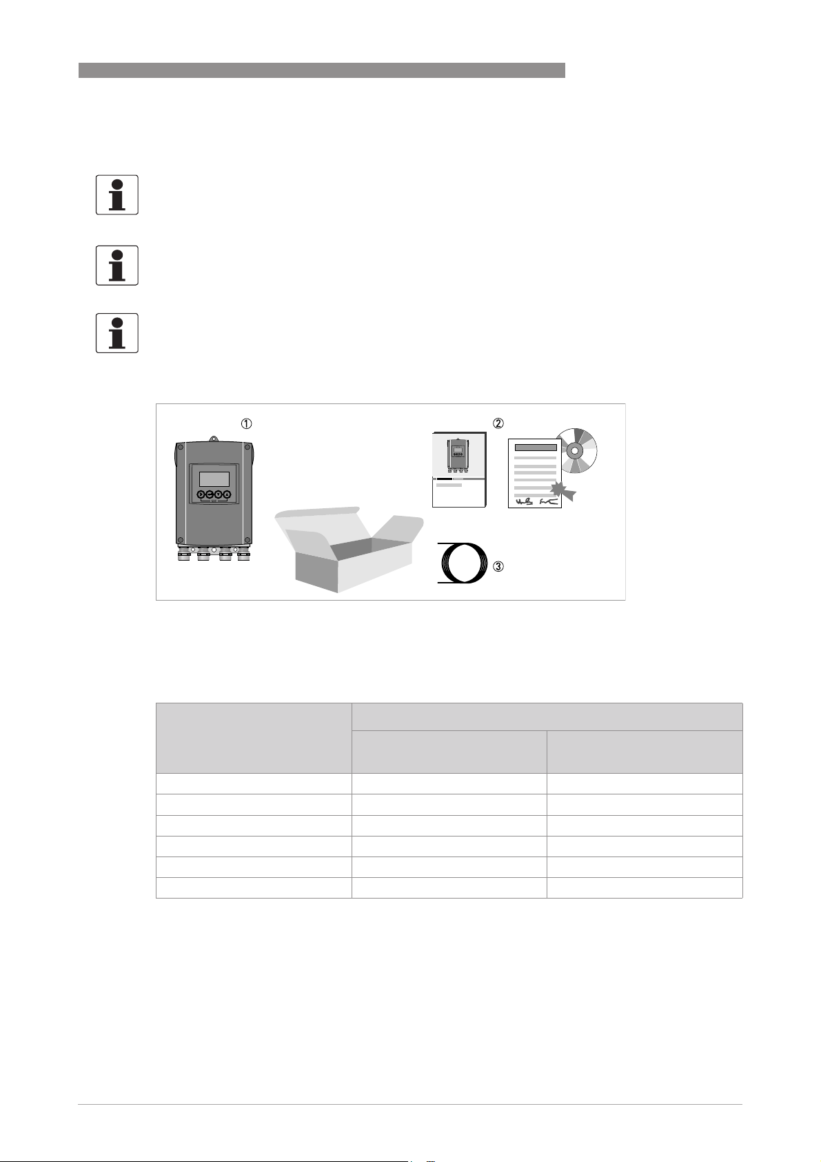
Figure 2-1: Scope of delivery
1 Device in the version as ordered
2 Documentation (calibration report, Quick Start, CD-Rom with product documentation for flow sensor and signal con-
verter)
3 Signal cable (only for remote version)
Flow sensor Flow sensor + signal converter IFC 100
Compact (0°/45° version) Remote wall-mounted
housing
OPTIFLUX 1000 OPTIFLUX 1100 C OPTIFLUX 1100 W
OPTIFLUX 2000 OPTIFLUX 2100 C OPTIFLUX 2100 W
OPTIFLUX 4000 OPTIFLUX 4100 C OPTIFLUX 4100 W
OPTIFLUX 5000 OPTIFLUX 5100 C OPTIFLUX 5100 W
OPTIFLUX 6000 OPTIFLUX 6100 C OPTIFLUX 6100 W
WATERFLUX 3000 WATERFLUX 3100 C WATERFLUX 3100 W
Table 2-1: Signal converter/flow sensor combination possibilities
www.krohne.com03/2018 - 4000124107 - QS IFC 100 R07 en
5
Page 6
2
INSTALLATION
2.3 Storage
• Store the device in a dry, dust-free location.
• Avoid continuous direct sunlight.
• Store the device in its original packing.
• Storage temperature: -40...+70°C / -40...+158°F
2.4 Transport
Signal converter
• No special requirements.
Compact version
• Do not lift the device by the signal converter housing.
• Do not use lifting chains.
• To transport flange devices, use lifting straps. Wrap these around both process connections.
IFC 100
2.5 Installation specifications
INFORMATION!
The following precautions must be taken to ensure reliable installation.
•
Make sure that there is adequate space to the sides.
•
The device must not be heated by radiated heat (e.g. exposure to the sun) to an electronics
housing surface temperature above the maximum permissible ambient temperature. If it is
necessary to prevent damage from heat sources, a heat protection (e.g. sun shade) has to be
installed.
•
Signal converters installed in control cabinets require adequate cooling, e.g. by fan or heat
exchanger.
•
Do not expose the signal converter to intense vibrations.
6
www.krohne.com 03/2018 - 4000124107 - QS IFC 100 R07 en
Page 7
IFC 100
2.6 Mounting of the compact version
CAUTION!
Turning the housing of the compact version is not permitted.
INFORMATION!
The signal converter is mounted directly on the flow sensor. For installation of the flowmeter,
please observe the instructions in the supplied product documentation for the flow sensor.
2.7 Mounting the wall-mounted housing, remote version
INFORMATION!
Assembly materials and tools are not part of the delivery. Use the assembly materials and tools
in compliance with the applicable occupational health and safety directives.
2.7.1 Wall mounting
INSTALLATION
2
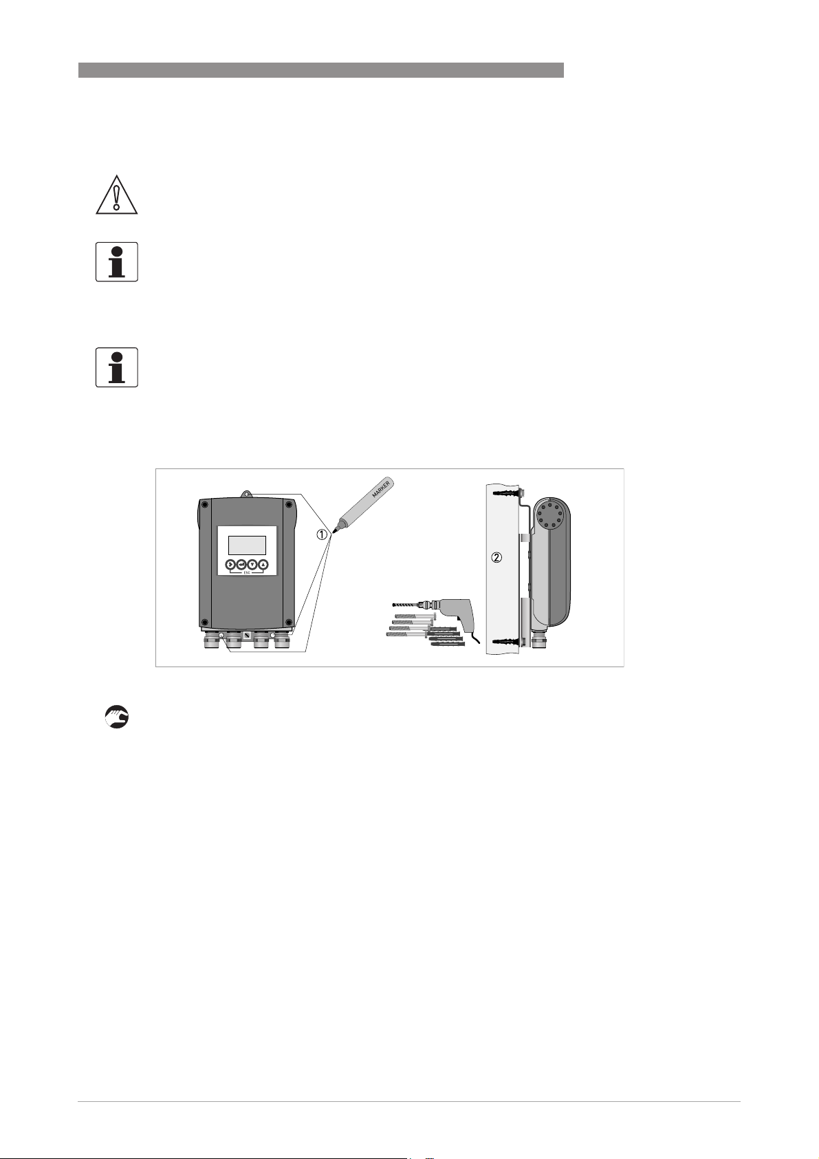
Figure 2-2: Mounting the wall-mounted housing
1 Prepare the holes with the aid of the mounting plate. For further information refer to
plate of wall-mounted version, aluminium housing
2 Fasten the device securely to the wall with the mounting plate.
on page 10.
Mounting
www.krohne.com03/2018 - 4000124107 - QS IFC 100 R07 en
7
Page 8
2
INSTALLATION
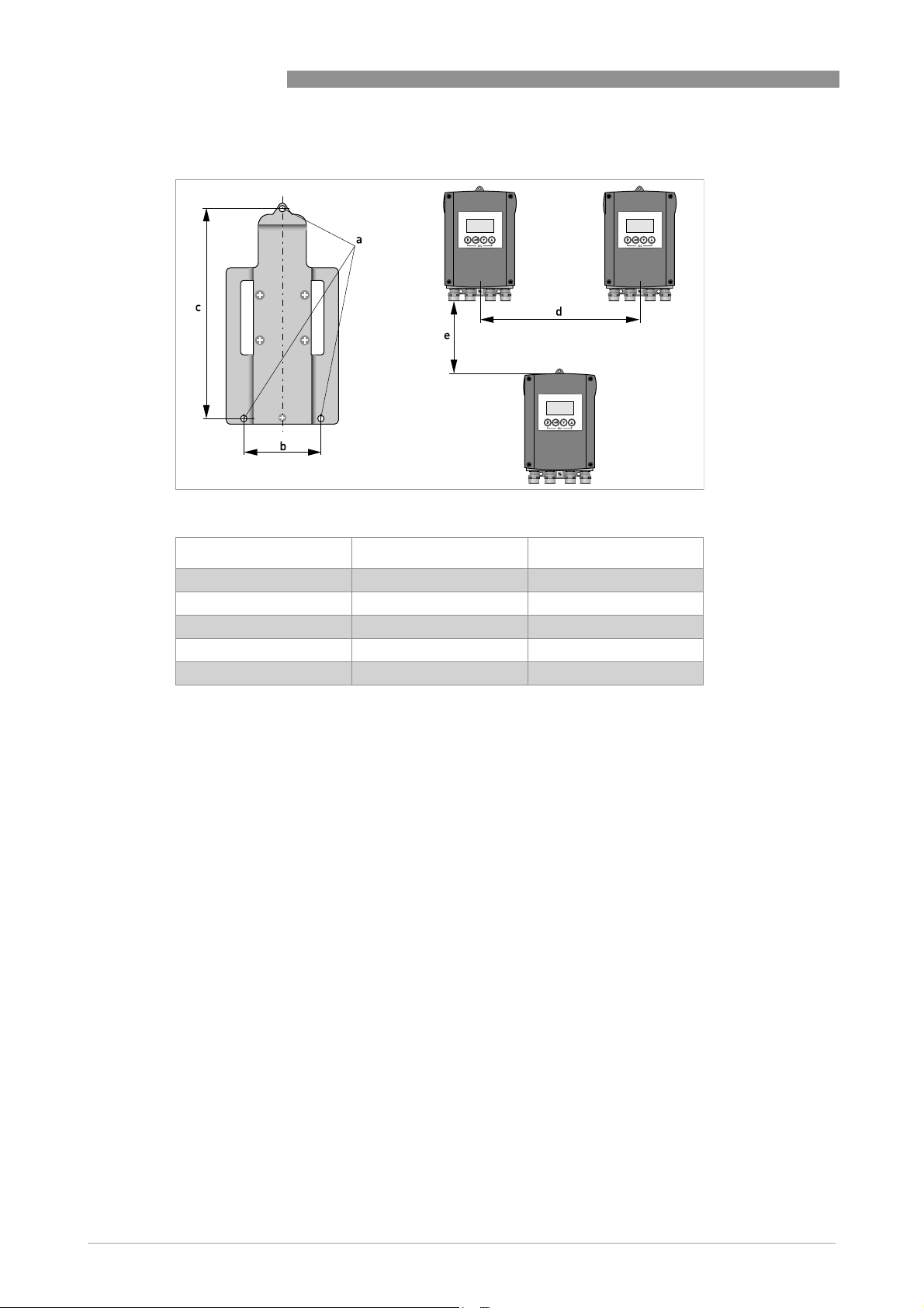
Figure 2-3: Wall mounting of multiple devices (aluminium housing)
IFC 100
[mm] [inch]
a Ø6.5 Ø0.26
b 87.2 3.4
c 241 9.5
d 310 12.2
e 257 10.1
Table 2-2: Dimensions in mm and inch
8
www.krohne.com 03/2018 - 4000124107 - QS IFC 100 R07 en
Page 9
IFC 100
INSTALLATION
e
2
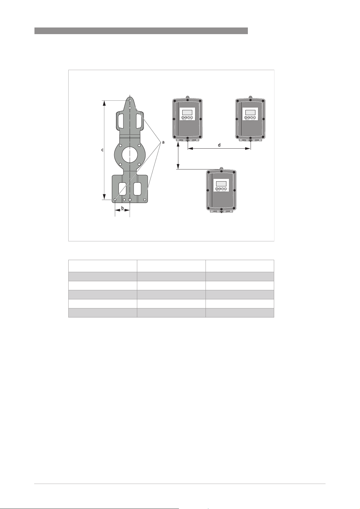
Figure 2-4: Wall mounting of multiple devices (stainless steel housing)
[mm] [inch]
a Ø6.5 Ø0.26
b 268 10.5
c 40 1.6
d 336 13.2
e 257 10.1
Table 2-3: Dimensions in mm and inch
www.krohne.com03/2018 - 4000124107 - QS IFC 100 R07 en
9
Page 10
2
INSTALLATION
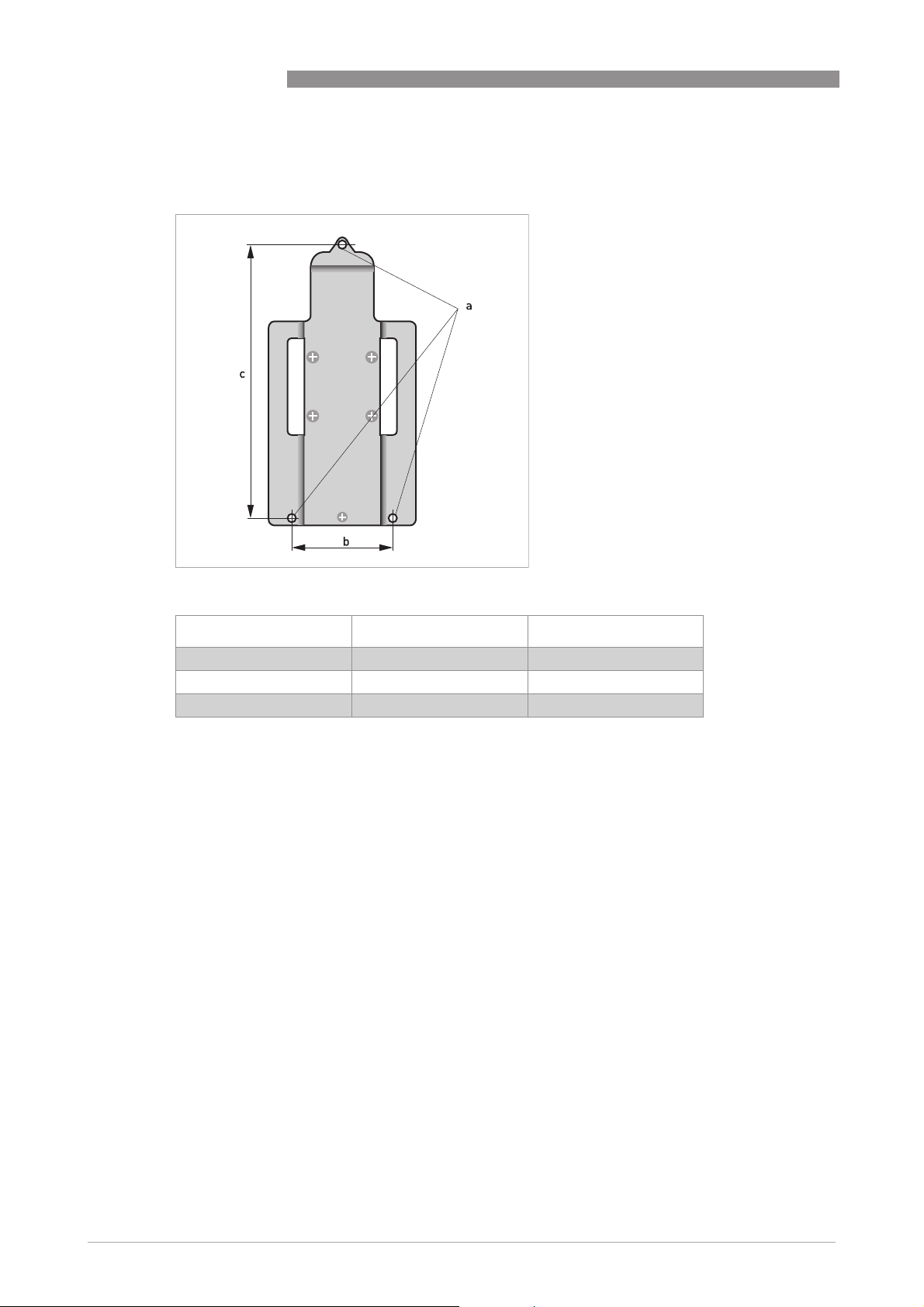
2.7.2 Mounting plate of wall-mounted version, aluminium housing
IFC 100
Figure 2-5: Dimensions of mounting plate of wall-mounted version, aluminium housing
[mm] [inch]
a Ø6.5 Ø0.26
b 87.2 3.4
c 241 9.5
Table 2-4: Dimensions in mm and inch
10
www.krohne.com 03/2018 - 4000124107 - QS IFC 100 R07 en
Page 11
IFC 100
INSTALLATION
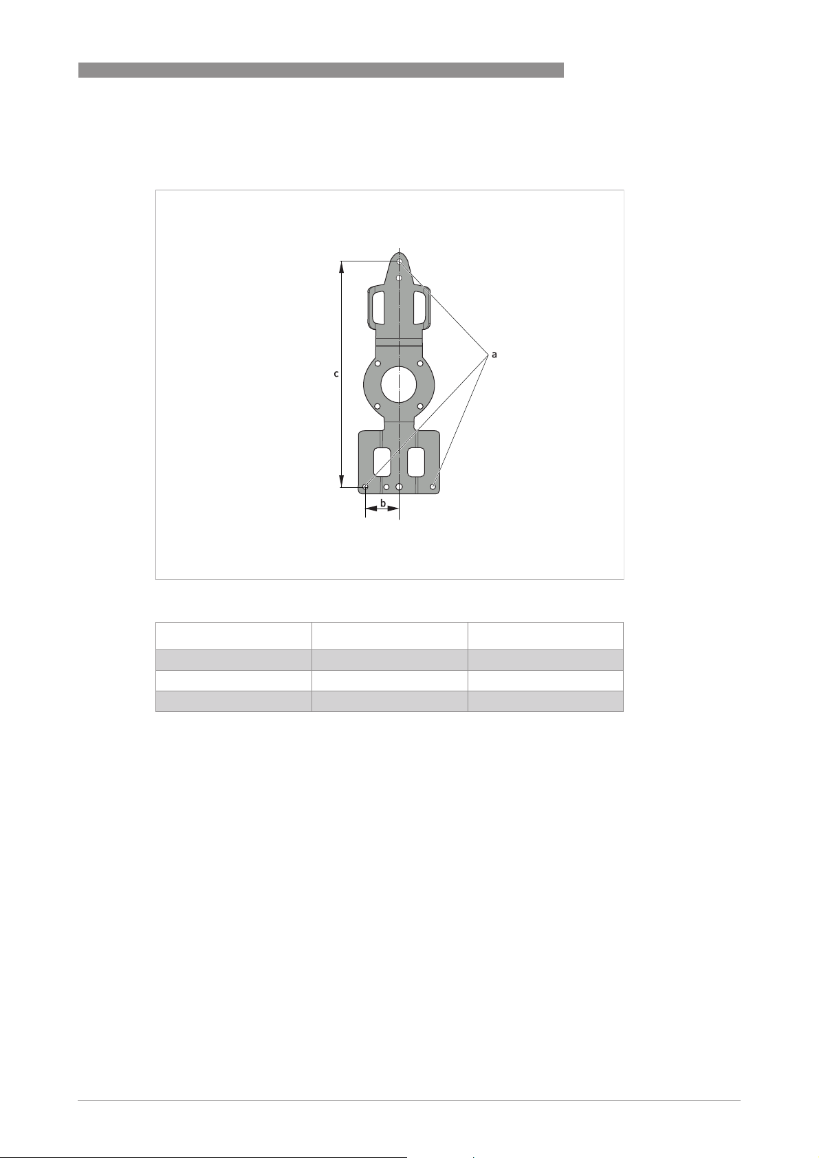
2.7.3 Mounting plate of wall-mounted version, stainless steel housing
2
Figure 2-6: Dimensions of mounting plate of wall-mounted version, stainless steel housing
[mm] [inch]
a Ø6.5 Ø0.26
b 40 1.6
c 267.9 10.55
Table 2-5: Dimensions in mm and inch
www.krohne.com03/2018 - 4000124107 - QS IFC 100 R07 en
11
Page 12

3
ELECTRICAL CONNECTIONS
3.1 Safety instructions
DANGER!
All work on the electrical connections may only be carried out with the power disconnected. Take
note of the voltage data on the nameplate!
DANGER!
Observe the national regulations for electrical installations!
DANGER!
For devices used in hazardous areas, additional safety notes apply; please refer to the Ex
documentation.
WARNING!
Observe without fail the local occupational health and safety regulations. Any work done on the
electrical components of the measuring device may only be carried out by properly trained
specialists.
IFC 100
INFORMATION!
Look at the device nameplate to ensure that the device is delivered according to your order.
Check for the correct supply voltage printed on the nameplate.
3.2 Important notes on electrical connection
DANGER!
Electrical connection is carried out in conformity with the VDE 0100 directive "Regulations for
electrical power installations with line voltages up to 1000 V" or equivalent national regulations.
DANGER!
The device must be grounded in accordance with regulations in order to protect personnel
against electric shocks.
CAUTION!
•
Use suitable cable entries for the various electrical cables.
•
The flow sensor and signal converter have been configured together at the factory. For this
reason, please connect the devices in pairs. Ensure that the flow sensor constant GK/GKL
(see nameplates) are identically set.
•
If delivered separately or when installing devices that were not configured together, set the
signal converter to the DN size and GK/GKL of the flow sensor.
12
www.krohne.com 03/2018 - 4000124107 - QS IFC 100 R07 en
Page 13

IFC 100
ELECTRICAL CONNECTIONS
3.3 Electrical cables for remote device versions, notes
3.3.1 Notes on signal cable A
INFORMATION!
Signal cable A (type DS 300) with double shield ensures proper transmission of measured
values.
Observe the following notes:
• Lay the signal cable with fastening elements.
• It is permissible to lay the signal cable in water or in the ground.
• The insulating material is flame-retardant.
• The signal cable does not contain any halogens and is unplasticized, and remains flexible at
low temperatures.
• The connection of the inner shield (10) is carried out via the stranded drain wire (1).
• The connection of the outer shield (60) is carried out via the stranded drain wire (6).
3.3.2 Notes on field current cable C
3
DANGER!
A shielded 2-wire copper cable is used for the field current cable. The shielding MUST
connected in the housing of the flow sensor and signal converter.
INFORMATION!
The field current cable is not part of the scope of delivery.
MUST be
MUSTMUST
www.krohne.com03/2018 - 4000124107 - QS IFC 100 R07 en
13
Page 14

3
ELECTRICAL CONNECTIONS
3.3.3 Requirements for signal cables provided by the customer
INFORMATION!
If the signal cable was not ordered, it is to be provided by the customer. The following
requirements regarding the electrical values of the signal cable must be observed:
Electrical safety
• According to low voltage directive or equivalent national regulations.
Capacitance of the insulated conductors
• Insulated conductor / insulated conductor < 50 pF/m
• Insulated conductor / shield < 150 pF/m
Insulation resistance
• R
• U
• I
> 100 GΩ xkm
iso
<24V
max
< 100 mA
max
IFC 100
Test voltages
• Insulated conductor / inner shield 500 V
• Insulated conductor / insulated conductor 1000 V
• Insulated conductor / outer shield 1000 V
Twisting of the insulated conductors
• At least 10 twists per meter, important for screening magnetic fields.
14
www.krohne.com 03/2018 - 4000124107 - QS IFC 100 R07 en
Page 15

IFC 100
ELECTRICAL CONNECTIONS
3.4 Preparing the signal and field current cables
INFORMATION!
Assembly materials and tools are not part of the delivery. Use the assembly materials and tools
in compliance with the applicable occupational health and safety directives.
3.4.1 Signal cable A (type DS 300), construction
• Signal cable A is a double-shielded cable for signal transmission between the flow sensor
and signal converter.
• Bending radius: ≥ 50 mm / 2"
3
Figure 3-1: Construction of signal cable A
1 Stranded drain wire (1) for the inner shield (10), 1.0 mm
2 Insulated wire (2), 0.5 mm
3 Insulated wire (3), 0.5 mm
4 Outer sheath
5 Insulation layers
6 Stranded drain wire (6) for the outer shield (60)
2
Cu / AWG 20
2
Cu / AWG 20
2
Cu / AWG 17 (not insulated, bare)
www.krohne.com03/2018 - 4000124107 - QS IFC 100 R07 en
15
Page 16

3
ELECTRICAL CONNECTIONS
3.4.2 Length of signal cable A
INFORMATION!
For temperatures of the medium above 150
intermediate socket are necessary. These are available including the changed electrical
connection diagrams.
°
C / 300°F, a special signal cable and a ZD
IFC 100
Flow sensor Nominal diameter Min. electrical
conductivity
DN [mm] [inch]
OPTIFLUX 1000 F 10...150 3/8...6 5 A1
OPTIFLUX 2000 F 25...150 1...6 20 A1
200...1200 8...48 20 A2
OPTIFLUX 4000 F 2.5...150 1/10...6 5 A1
200...1200 8...48 5 A2
OPTIFLUX 5000 F 2.5...100 1/10...4 5 A1
150...250 6...10 5 A2
OPTIFLUX 6000 F 2.5...150 1/10...6 5 A1
WATERFLUX 3000 F 25...600 1...24 20 A1
[µS/cm]
Curve for signal
cable A
16
Figure 3-2: Maximum length of signal cable A
1 Maximum length of signal cable A between the flow sensor and signal converter [m]
2 Maximum length of signal cable A between the flow sensor and signal converter [ft]
3 Electrical conductivity of the medium being measured [μS/cm]
www.krohne.com 03/2018 - 4000124107 - QS IFC 100 R07 en
Page 17

IFC 100
ELECTRICAL CONNECTIONS
3.4.3 Preparing signal cable A, connection to signal converter
INFORMATION!
Assembly materials and tools are not part of the delivery. Use the assembly materials and tools
in compliance with the applicable occupational health and safety directives.
• Connection of the two shields in the signal converter is carried out via the stranded drain
wires.
• Bending radius: ≥ 50 mm / 2"
Required materials
• PVC insulating tube, Ø2.5 mm / 0.1"
• Heat-shrinkable tubing
• 2 wire end ferrules to DIN 46228: E 1.5-8 for the stranded drain wires (1, 6)
• 2 wire end ferrules to DIN 46228: E 0.5-8 for the insulated conductors (2, 3)
3
Figure 3-3: Preparation of signal cable A
a = 80 mm / 3.15"
1 Strip the conductor to dimension a.
2 Cut off the inner shield (10) and the outer shield (60). Make sure not to damage the stranded
drain wires (1, 6).
3 Slide the insulating tubes over the stranded drain wires (1, 6).
4 Crimp the wire end ferrules onto the stranded drain wire.
5 Crimp the wire end ferrules onto the conductors (2, 3).
6 Pull the heat-shrinkable tubing over the prepared signal cable.
www.krohne.com03/2018 - 4000124107 - QS IFC 100 R07 en
17
Page 18

3
ELECTRICAL CONNECTIONS
3.4.4 Preparing field current cable C, connection to signal converter
DANGER!
A shielded 2-wire copper cable is used as the field current cable. The shielding MUST
connected in the housing of the flow sensor and signal converter.
INFORMATION!
Assembly materials and tools are not part of the delivery. Use the assembly materials and tools
in compliance with the applicable occupational health and safety directives.
• Field current cable C is not part of the scope of delivery.
• Bending radius: ≥ 50 mm / 2"
Required materials:
• Shielded, at least 2-wire copper cable with suitable heat-shrinkable tubing
• Insulating tube, size according to the cable being used
• Wire end ferrules to DIN 46228: size according to the cable being used
MUST be
MUSTMUST
IFC 100
Length and cross-section of field current cable C
Length Cross-section AF (Cu)
[m] [ft]
0...150 0...492 2 x 0.75 Cu
150...300 492...984 2 x 1.5 Cu
300...600 984...1968 2 x 2.5 Cu
1 Cu = copper cross-section
[mm2]
1
1
1
[AWG]
2 x 18
2 x 14
2 x 12
18
www.krohne.com 03/2018 - 4000124107 - QS IFC 100 R07 en
Page 19

IFC 100
ELECTRICAL CONNECTIONS
Figure 3-4: Field current cable C, preparation for the signal converter
a = 80 mm / 3.15"
1 Strip the conductor to dimension a.
2 If a stranded drain wire is present, remove the shield that is present. Make sure not to damage
the stranded drain wire.
3 Slide an insulating tube over the stranded drain wire.
4 Crimp a wire end ferrule onto the stranded drain wire.
5 Crimp the wire end ferrules on the conductors.
6 Pull a shrinkable tube over the prepared cable.
3
www.krohne.com03/2018 - 4000124107 - QS IFC 100 R07 en
19
Page 20

3
ELECTRICAL CONNECTIONS
3.4.5 Preparing signal cable A, connection to flow sensor
INFORMATION!
Assembly materials and tools are not part of the delivery. Use the assembly materials and tools
in compliance with the applicable occupational health and safety directives.
• The outer shield (60) is connected in the terminal compartment of the flow sensor directly via
the shield and a clip.
• Bending radius: ≥ 50 mm / 2"
Required materials
• PVC insulating tube, Ø2.0...2.5 mm / 0.08...0.1"
• Heat-shrinkable tubing
• Wire end ferrule to DIN 46228: E 1.5-8 for the stranded drain wire (1)
• 2 wire end ferrules to DIN 46228: E 0.5-8 for the insulated conductors (2, 3)
IFC 100
20
Figure 3-5: Preparing signal cable A, connection to flow sensor
a = 50 mm / 2"
b = 10 mm / 0.4"
1 Strip the conductor to dimension a.
2 Trim the outer shield (60) to dimension b and pull it over the outer sheath.
3 Remove the stranded drain wire (6) of the outer shield and the inner shield. Make sure not to
damage the stranded drain wire (1) of the inner shield.
4 Slide an insulating tube over the stranded drain wire (1).
5 Crimp the wire end ferrules onto conductors 2 and 3 and the stranded drain wire (1).
6 Pull the heat-shrinkable tubing over the prepared signal cable.
www.krohne.com 03/2018 - 4000124107 - QS IFC 100 R07 en
Page 21

IFC 100
ELECTRICAL CONNECTIONS
3.4.6 Preparing field current cable C, connection to flow sensor
INFORMATION!
Assembly materials and tools are not part of the delivery. Use the assembly materials and tools
in compliance with the applicable occupational health and safety directives.
• The field current cable is not part of the scope of delivery.
• The shield is connected in the terminal compartment of the flow sensor directly via the shield
and a clip.
• Bending radius: ≥ 50 mm / 2"
Required materials
• Shielded 2-wire insulated copper cable
• Insulating tube, size according to the cable being used
• Heat-shrinkable tubing
• Wire end ferrules to DIN 46228: size according to the cable being used
3
Figure 3-6: Preparation of field current cable C
a = 50 mm / 2"
b = 10 mm / 0.4"
1 Strip the conductor to dimension a.
2 Trim the outer shield to dimension b and pull it over the outer sheath.
3 Crimp wire end ferrules onto both conductors.
4 Pull a shrinkable tube over the prepared cable.
www.krohne.com03/2018 - 4000124107 - QS IFC 100 R07 en
21
Page 22

3
ELECTRICAL CONNECTIONS
3.5 Connecting the signal and field current cables
DANGER!
Cables may only be connected when the power is switched off.
DANGER!
The device must be grounded in accordance with regulations in order to protect personnel
against electric shocks.
DANGER!
For devices used in hazardous areas, additional safety notes apply; please refer to the Ex
documentation.
WARNING!
Observe without fail the local occupational health and safety regulations. Any work done on the
electrical components of the measuring device may only be carried out by properly trained
specialists.
IFC 100
3.5.1 Connecting the signal and field current cables to the signal converter, remote
version
INFORMATION!
The compact version is supplied preassembled from the factory.
Opening and closing the aluminium housing
Figure 3-7: Opening and closing the aluminium housing
1 Loosen the 4 screws with a suitable tool.
2 Lift the housing at the top and bottom at the same time.
3 Slide the housing cover upward.
4 The housing cover is guided and held by the inside hinge.
i There is now access to the terminal compartment for connection.
22
After completion of work, close the signal converter housing.
www.krohne.com 03/2018 - 4000124107 - QS IFC 100 R07 en
Page 23

IFC 100
ELECTRICAL CONNECTIONS
Opening and closing the stainless steel housing
Figure 3-8: Opening and closing the stainless steel housing
1 Loose the 8 hexagon screws with a 10 mm spanner socket.
2 Lift the housing at the top and bottom at the same time.
3 Slide the housing cover backward.
4 The housing cover is guided and held by the inside hinge.
i There is now access to the terminal compartment for connection.
3
After completion of work, close the signal converter housing. To achieve a proper sealing of the
device tighten the screws in the following order with a torque of 5 Nm.
Figure 3-9: Tighten the screws
www.krohne.com03/2018 - 4000124107 - QS IFC 100 R07 en
23
Page 24

3
ELECTRICAL CONNECTIONS
Connecting the signal and field current cables
Figure 3-10: Function of the electrical connection terminal
Connect the electrical conductors as follows:
1 Push the lever downwards with a screwdriver in good condition (blade: 3.5 mm wide and
0.5 mm thick).
2 Insert the electrical conductor into the plug.
3 The conductor will be clamped as soon as the lever is released.
IFC 100
24
Figure 3-11: Connecting the signal and field current cables
1 Cable entry for field current cable
2 Cable entry for signal cable
3 Connecting the field current cable shield
4 Electrical conductor (7)
5 Electrical conductor (8)
6 Stranded drain wire (1) of the inner shield (10) of the signal cable
7 Electrical conductor (2)
8 Electrical conductor (3)
9 Stranded drain wire (S) of the outer shield (60)
www.krohne.com 03/2018 - 4000124107 - QS IFC 100 R07 en
Page 25

IFC 100
ELECTRICAL CONNECTIONS
3.5.2 Connection diagram for signal and field current cable
DANGER!
The device must be grounded in accordance with regulations in order to protect personnel
against electric shocks.
3
• A shielded 2-wire copper cable is used as the field current cable. The shielding MUST
MUST be
MUSTMUST
connected in the housing of the flow sensor and signal converter.
• The outer shield (60) is connected in the terminal compartment of the flow sensor directly via
the shield and a clip.
• Bending radius of signal and field current cable: ≥ 50 mm / 2"
• The following illustration is schematic. The positions of the electrical connection terminals
may vary depending on the housing version.
Figure 3-12: Connection diagram for signal and field current cable
1 Electrical terminal compartment in the signal converter
2 Signal cable A
3 Field current cable C
4 Electrical terminal compartment in the flow sensor
5 Functional ground FE
www.krohne.com03/2018 - 4000124107 - QS IFC 100 R07 en
25
Page 26

3
ELECTRICAL CONNECTIONS
3.6 Grounding the flow sensor
3.6.1 Classical method
CAUTION!
There should be no difference in potential between the flow sensor and the housing or protective
earth of the signal converter!
• The flow sensor must be properly grounded.
• The grounding cable should not transmit any interference voltages.
• Do not use the grounding cable to connect any other electrical devices to ground at the same
time.
• The flow sensors are connected to ground by means of a functional grounding conductor FE.
• Special grounding instructions for the various flow sensors are provided in the separate
documentation for the flow sensor.
• The documentation for the flow sensor also contain descriptions on how to use grounding
rings and how to install the flow sensor in metal or plastic pipes or in pipes which are coated
on the inside.
IFC 100
26
www.krohne.com 03/2018 - 4000124107 - QS IFC 100 R07 en
Page 27

IFC 100
3.7 Connecting the power supply
DANGER!
The device must be grounded in accordance with regulations in order to protect personnel
against electric shocks.
• The housings of the devices, which are designed to protect the electronic equipment from
dust and moisture, should be kept well closed at all times. Creepage distances and
clearances are dimensioned to VDE 0110 and IEC 60664 for pollution severity 2. Supply
circuits are designed for overvoltage category III and the output circuits for overvoltage
category II.
• Fuse protection (I
breaker) to isolate the signal converter must be provided.
≤ 16 A) for the infeed power circuit, and also a separator (switch, circuit
N
ELECTRICAL CONNECTIONS
3
Figure 3-13: Terminal compartment for power supply
1 Retaining band of the cover
2 Cable entry for power supply, remote version
3 Cable entry for power supply, compact version
Version overview
Version Non-Ex Ex
100...230 VAC Standard Optional
24 VDC Standard -
24 VAC/DC Standard Optional
www.krohne.com03/2018 - 4000124107 - QS IFC 100 R07 en
27
Page 28

3
ELECTRICAL CONNECTIONS
• Open the cover of the electrical terminal compartment by pressing down and pulling forwards
at the same time.
Figure 3-14: Power supply connection
1 100...230 VAC (-15% / +10%), 8 VA
2 24 VDC (-55% / +30%), 4 W
3 24 VAC/DC (AC: -15% / +10%; DC: -25% / +30%), 7 VA or 4 W
• Close the cover after the power has been connected.
IFC 100
100...230 VAC (tolerance range for 100 VAC: -15% / +10%)
100...230 VAC (tolerance range for 100 VAC: -15% / +10%)
100...230 VAC (tolerance range for 100 VAC: -15% / +10%)100...230 VAC (tolerance range for 100 VAC: -15% / +10%)
• Note the power supply voltage and frequency (50...60 Hz) on the nameplate.
INFORMATION!
240 VAC + 5% is included in the tolerance range.
24 VDC (tolerance range: -55% / +30%)
24 VDC (tolerance range: -55% / +30%)
24 VDC (tolerance range: -55% / +30%)24 VDC (tolerance range: -55% / +30%)
• Note the data on the nameplate!
• When connecting to functional extra-low voltages, provide a facility for protective separation
(PELV) (acc. to VDE 0100 / VDE 0106 and/or IEC 60364 / IEC 61140 or relevant national
regulations).
INFORMATION!
12 VDC - 10% is included in the tolerance range.
24 VAC/DC (tolerance range: AC: -15% / +10%; DC: -25% / +30%)
24 VAC/DC (tolerance range: AC: -15% / +10%; DC: -25% / +30%)
24 VAC/DC (tolerance range: AC: -15% / +10%; DC: -25% / +30%)24 VAC/DC (tolerance range: AC: -15% / +10%; DC: -25% / +30%)
• AC: Note the power supply voltage and frequency (50...60 Hz) on the nameplate.
• AC/DC: When connecting to functional extra-low voltages, provide a facility for protective
separation (PELV) (acc. to VDE 0100 / VDE 0106 and/or IEC 60364 / IEC 61140 or relevant
national regulations).
28
INFORMATION!
12 V is not
not included in the tolerance range.
notnot
www.krohne.com 03/2018 - 4000124107 - QS IFC 100 R07 en
Page 29

IFC 100
3.8 Overview of outputs
3.8.1 Description of the CG number
Figure 3-15: Marking (CG number) of the electronics module and output variants
1 ID number: 0
2 ID number: 0 = standard; 9 = special
3 Power supply
4 Display (language versions)
5 Output version
3.8.2 Fixed, non-alterable output versions
This signal converter is available with various output combinations.
ELECTRICAL CONNECTIONS
3
• The grey boxes in the tables denote unassigned or unused connection terminals.
• In the table, only the final digits of the CG no. are depicted.
• Connection terminal A+ is only operable in the basic output version.
CG no. Connection terminals
C C- D D- S A+ A A-
1 0 0 Sp 1 Pp / Sp passive 1 2
Table 3-1: Basic outputs
1 Function change by software
2 Shielding
3 Function changed by reconnecting
I
I
a
P
p
S
p
Table 3-2: Description of used abbreviations
Current output active or passive
p
Pulse/frequency output passive
Status output / limit switch passive
Ip + HART® passive 3
Ia + HART® active 3
www.krohne.com03/2018 - 4000124107 - QS IFC 100 R07 en
29
Page 30

3
ELECTRICAL CONNECTIONS
3.9 Electrical connection of the outputs
INFORMATION!
Assembly materials and tools are not part of the delivery. Use the assembly materials and tools
in compliance with the applicable occupational health and safety directives.
3.9.1 Electrical connection of the outputs
DANGER!
All work on the electrical connections may only be carried out with the power disconnected. Take
note of the voltage data on the nameplate!
IFC 100
Figure 3-16: Connection of outputs
1 Cable entry, remote version
2 Cable entry, compact version
3 Terminal S for shield
• Open the housing cover
• Push the prepared cables through the cable entries and connect the necessary conductors.
• Connect the shield.
• Close the housing cover.
INFORMATION!
Ensure that the housing gasket is properly fitted, clean and undamaged.
30
www.krohne.com 03/2018 - 4000124107 - QS IFC 100 R07 en
Page 31

IFC 100
3.9.2 Laying electrical cables correctly
Figure 3-17: Protect housing from dust and water
1 For compact versions with nearly horizontally-oriented cable entries, lay the necessary elec-
tric cables with a drip loop as shown in the illustration.
2 Tighten the screw connection of the cable entry securely.
3 Seal cable entries that are not needed with a plug.
ELECTRICAL CONNECTIONS
3
www.krohne.com03/2018 - 4000124107 - QS IFC 100 R07 en
31
Page 32

4
START-UP
4.1 Switching on the power
Before connecting to power, please check that the system has been correctly installed.
This includes:
• The device must be mechanically safe and mounted in compliance with the regulations.
• The power connections must have been made in compliance with the regulations.
• The electrical terminal compartments must be secured and the covers have been screwed
on.
• Check that the electrical operating data of the power supply are correct.
• Switching on the power.
4.2 Starting the signal converter
The measuring device, consisting of the flow sensor and the signal converter, is supplied ready
for operation. All operating data have been set at the factory in accordance with your order
specifications.
IFC 100
When the power is switched on, a self test is carried out. After that the device immediately
begins measuring, and the current values are displayed.
Figure 4-1: Displays in measuring mode (examples for 2 or 3 measured values)
x, y and z denote the units of the measured values displayed
It is possible to change between the two measured value windows, the trend display and the list
with the status messages by pressing the keys ↑ and ↓.
32
www.krohne.com 03/2018 - 4000124107 - QS IFC 100 R07 en
Page 33

IFC 100
NOTES
5
www.krohne.com03/2018 - 4000124107 - QS IFC 100 R07 en
33
Page 34

5
NOTES
IFC 100
34
www.krohne.com 03/2018 - 4000124107 - QS IFC 100 R07 en
Page 35

IFC 100
NOTES
5
www.krohne.com03/2018 - 4000124107 - QS IFC 100 R07 en
35
Page 36

KROHNE – Process instrumentation and measurement solutions
•
Flow
•
Level
•
Temperature
•
Pressure
•
Process Analysis
•
Services
Head Office KROHNE Messtechnik GmbH
Ludwig-Krohne-Str. 5
47058 Duisburg (Germany)
Tel.: +49 203 301 0
Fax: +49 203 301 10389
info@krohne.com
The current list of all KROHNE contacts and addresses can be found at:
© KROHNE 03/2018 - 4000124107 - QS IFC 100 R07 en - Subject to change without notice.
www.krohne.com
 Loading...