


© KROHNE |
7.02568.21.00 |
|
|
|
|
|
|
|
|
|
|
||
|
|
|
|
|
|
|

 18.10.2005
Installation and operating instructions
BATCHCONTROL 5014 C
Compact Electromagnetic
Flowmeters with CANopen bus interface
Please note!
Do not open the housing of the BATCHCONTROL 5014C.
Danger of contamination with substances likely to destroy the moisture barrier of the electronic equipment (e.g. if CIP or SIP cleaned from the outside).
Therefore, please contact your KROHNE Service engineer before you open the housing.

Contents
System description |
|
4 |
||
Standards and approvals |
|
4 |
||
Product liability and warranty |
|
4 |
||
Functional description BATCHCONTROL IFM 5014C |
|
5 |
||
Part A System installation and start-up |
6 |
- 15 |
||
1 |
Installation in the pipeline |
6 |
- 12 |
|
1.1 |
Important information |
|
6 |
|
1.2 |
Suggestions for installation |
|
7 |
|
1.3 |
Installation requirements |
|
8 |
|
1.3.1 |
Position of flange |
|
9 |
|
1.3.2 |
Example: centering and sealing the primary head |
|
9 |
|
1.3.3 |
Grounding |
|
9 |
|
1.4 |
Installation of the primary head |
|
10 |
|
1.4.1 |
Device description |
|
10 |
|
1.4.2 |
Installation of the IFM 5014C |
|
10 |
|
1.5 |
Size of connections |
11 |
- 12 |
|
1.5.1 |
Fastening with tie bolts |
|
11 |
|
1.5.2 |
Fastening with bolts (option) |
|
12 |
|
2 |
Electrical connection |
13 |
- 14 |
|
2.1 |
Important information |
|
13 |
|
2.2 |
Attachment plugs |
|
13 |
|
2.3 |
Power supply and CAN bus |
|
14 |
|
2.4 |
Input and output |
|
14 |
|
2.5 |
Block circuit diagram |
|
14 |
|
3 |
Start-up |
|
15 |
|
3.1 |
Checking for availability |
|
15 |
|
3.2 |
Factory settings |
|
15 |
|
Part B IFC 014 batch controller |
16 |
- 20 |
||
4 |
Description of functions |
16 |
- 20 |
|
4.1 |
Contact outputs |
|
16 |
|
4.2 |
Voltage input |
|
16 |
|
4.3 |
Contact input |
|
16 |
|
4.4 |
CAN bus and parameter |
16 |
- 17 |
|
4.5 |
Temperature sensors |
|
17 |
|
4.6 |
Flow sensor |
|
17 |
|
4.7 |
An example for a filling process |
17 |
- 20 |
|
Part C Service |
|
21 |
||
5 |
Illustrations of printed circuit boards |
|
21 |
|
Part D Technical Data, block diagram and measuring principle |
22 |
- 28 |
||
6 |
Technical data |
22 |
- 26 |
|
6.1 |
Flow during filling and fill volume |
|
22 |
|
6.2 |
Flowmeters |
|
22 |
|
6.3 |
Signal converter |
|
23 |
|
6.4 |
Error limits at reference conditions |
|
24 |
|
6.5 |
Dimensions and weights |
25 |
- 26 |
|
6.6 |
Instrument nameplates |
|
26 |
|
7 |
Block diagram |
|
27 |
|
|
|
|
|
|
2 BATCHCONTROL |
Installation and operating instructions |
|
|
|

8 Measuring principle 28
Part E Annex |
29 - 47 |
|
E1 |
Index |
29 |
E2 |
CAN parameter |
30 - 45 |
E3 |
Form to accompany returned device |
46 |
Please note!
Do not open the housing of the BATCHCONTROL IFM 5014C.
Danger of contamination with substances likely to destroy the moisture barrier of the electronic equipment (e.g. if CIP or SIP cleaned from the outside).
Therefore, please contact your KROHNE Service engineer before you open the housing.
Installation and operating instructions |
BATCHCONTROL |
3 |

System description
The BATCHCONTROL IFM 5014C compact electromagnetic flowmeter is a precision instrument designed for the linear flow measurement of liquid products and controlling the filling process.
The products need to be electrically conductive:
>5 µS/cm (except for water)
>20 µS/cm (for water)
The full-scale range Q100% can be set as a function of the meter size:
DN 2.5 – 40 and 1/10” – 11/2” Q100% = 0.0015 - 15 l/s
This is equivalent to a flow velocity of 0.2 - 12 m/s.
Standards and approvals
•BATCHCONTROL IFM 5014C with the IFC014 signal converter meets the EU-EMC Directives and bears the CE and 3A symbol.
•The 3A approval covers only the meter without adapter.
•All factories and production sequences are ISO 9001 certified.
Product liability and warranty
The compact BATCHCONTROL IFM 5014C electromagnetic flowmeter is designed exclusively for measuring the volumetric flowrate of electrically conductive, liquid process products.
The compact flowmeter is not suitable for use in hazardous areas. Other flowmeter series are available for such applications.
Responsibility as to suitability and intended use of this compact electromagnetic flowmeter rests solely with the operator.
Improper installation and operation of the flowmeters (systems) may lead to loss of warranty.
In addition, the “General conditions of sale“ forming the basis of the purchase contract are applicable.
If BATCHCONTROL 5014C flowmeters need to be returned to KROHNE, please note the information given on the last-but-one page of these instructions. KROHNE regret that they cannot repair or check your flowmeter(s) unless these are accompanied by the completed form sheet.
4 BATCHCONTROL |
Installation and operating instructions |
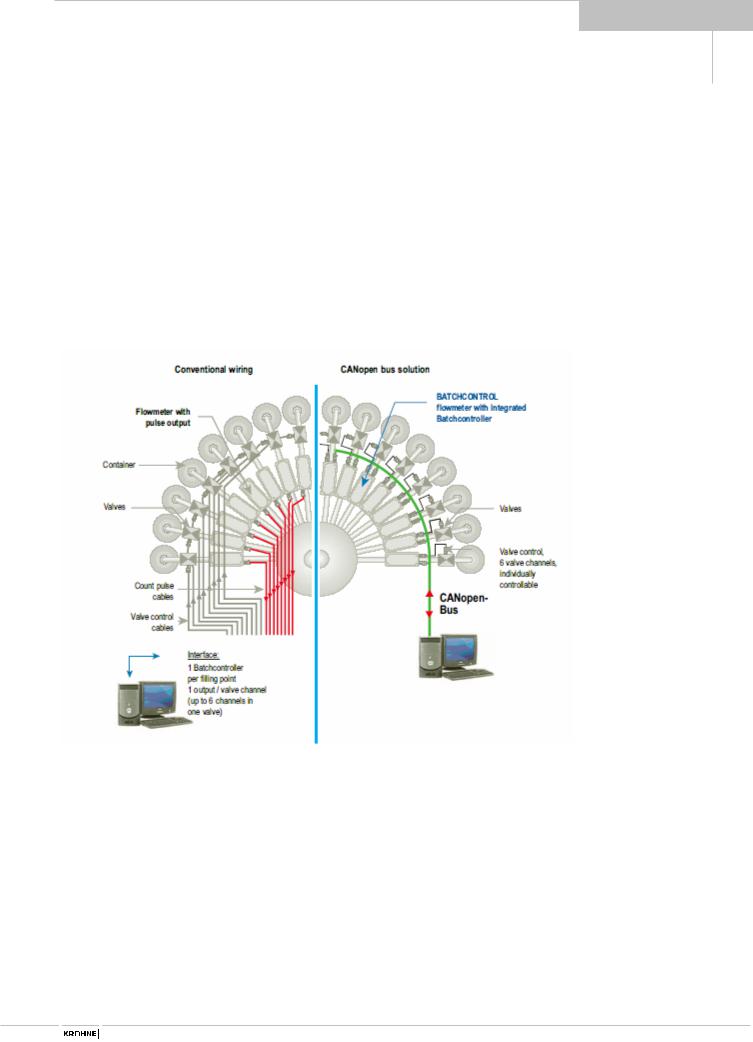
Functional description
BATCHCONTROL IFM 5014C
The volume to be filled into the container is measured “in line“ by means of the electromagnetic flowmetering system. The BATCHCONTROL closes the filling valve once the preset filling volume has been reached. It is always the preset target volume that is filled into the container.
The signal converter converts the measured flowrate signal into volume that are transfered to the integrated batch controller.
The influence of valve closing times and other dynamic factors can be corrected by the adaptive correction formalism of the BATCHCONTROL 5014C.
The use of state-of-the-art microprocessor electronics and the high-speed analog/digital converter also enables changes in the flowrate to be sensed precisely. This technology ensures high reproducibility and long-term stability.
Installation and operating instructions |
BATCHCONTROL |
5 |

1
Part A System installation and start-up
1 Installation in the pipeline
1.1Important information
The following recommendations should be observed to ensure proper functioning of the flowmeter – PLEASE NOTE.
•Measuring tube must be filled completely at all times.
•Direction of flow: the blue arrow on the housing of the primary head must point in the direction of flow. If for structural reasons the flowmeter can only be installed invers to the direction of flow, the direction of flow measurement can be reprogrammed.
•Stud bolts and nuts: to fit, make sure there is sufficient room next to the pipe flanges.
•Vibration: support the pipeline on both
sides of the flowmeter. Vibration level to IEC 068-2-34: below 2,2g in the 20 - 2000 Hz frequency range.
•Radiant heat: avoid e.g. from hot product tanks, insulate if necessary.
•Avoid strong electromagnetic fields in vicinity of flowmeter.
•Straight Inlet run ≥ 5 x DN and straight outlet run ≥ 2 x DN, measured from the electrode axis (DN = meter size).
•Vortex or corkscrew flow: increase length of inlet and outlet runs or install flow straighteners.
•Mixing different process liquids: install flowmeter upstream of mixing point or at an adequate distance downstream, minimum of 30 x DN (DN = meter size), otherwise display may be unsteady.
•Plastic pipes and internally coated metal pipes: grounding rings required, see “Grounding“, Section 1.3.3.
•Heat-insulated pipelines: do not insulate flowmeter.
•Zero setting: not required. For checking purpose, it should be possible to set “zero“ flow velocity in the completely filled measuring tube. Shutoff valves should therefore be provided either downstream or upstream and downstream of the flowmeter.
•Ambient temperature
-25°C to +60°C
•Process temperature max. 140 °C
•Transport and storage temperature
-25°C to +60°C
Limits imposed by the material used for the measuring tube for process temperature, thermal shock limit, pressure and vacuum, see Section D page 22.
Please note!
The ceramic measuring tube must not contact metal parts (flange, pipeline). This can destroy the flowmeter!
6 BATCHCONTROL |
Installation and operating instructions |
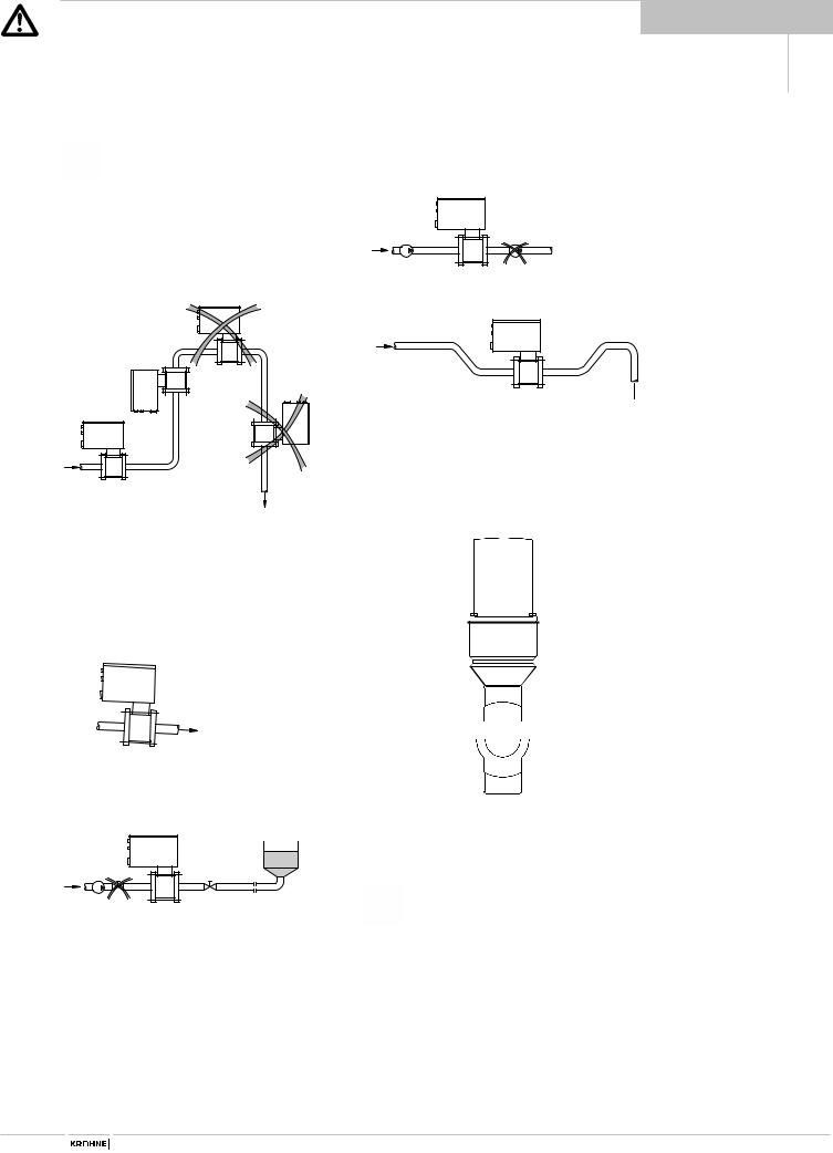
1.2Suggestions for installation
To avoid measuring errors due to air inclusion and vacuum, please observe the following:
Highest point of pipe run
(Air bubbles collect in measuring tube - faulty measurements!)
Preferred locations
downpipe
(open discharge)
Avoid draining or partial filling of the measuring tube. Faulty measurements.
Horizontal pipe run
Install in slightly descending pipe section to prevent air from collecting, so avoiding faulty measurements and that meter can drain.
1
Pumps
Do not install flowmeter on pump suction side
Open feed or discharge
Install meter in low section of pipe
open discharge 
Selecting the installation location
Location and position as required, but electrode axis (X – – – – X
must be approximately horizontal in a horizontal pipe run.
Control and shutoff valves: always install behind the flowmeter
x 


 x
x
Direction of flow The blue arrow on the primary head housing must point in the flow direction.
On high-temperature pipes and where process temperatures exceed 100 °C, provide facilities to compensate for longitudinal expansion on heat-up of the pipeline. Use flexible pipe elements (e.g. elbows).
Installation and operating instructions |
BATCHCONTROL |
7 |

1
1.3Installation requirements
Items supplied with flowmeter
•BATCHCONTROL IFM 5014C compact flowmeter in the version as ordered
•Installation and operating instructions, as agreed
•Certificate of system calibration data (as agreed)
Excluding fitting accessories. Stud bolts, gaskets, etc., to be provided by customer.
All operating data and function values are factory set according to your order specifications.
Requirements
Use in the food industry
The IFM 5014C is specifically suitable for use in the food and beverage industry or similar sterile processes.
The IFM 5014C is steam-resistant.
The measuring tube can be SIP or CIP cleaned when in installed condition. During the cleaning the meter(s) must be switched off to maintain the reliability of the unit(s).
•Operating pressure, type, and space between pipe flanges: see Table.
•Tighten stud bolts uniformly down to the metal stop in diagonally opposed sequence. See Table for type and number of stud bolts.
•Install meter vertically or in a slope due to
its conical in/outlet.
On DN 15 (1/2”) and DN 32 (11/4” ) a BATCHCONTROL with straight ceramic tube is avaible.
DIN 2501 |
ANSI B 16.5 |
Space between |
Bolts |
|
Max torque |
|||
|
|
|
|
|
|
|
|
|
and JIS |
|
pipe flanges |
|
Nm |
|
kpm |
ft × lbf |
|
|
|
|
|
|
|
|
|
|
DN |
2.5 |
1/10" |
51.8 mm (2.04") |
4 x M12 |
10 |
|
1.0 |
7.2 |
DN |
4 |
1/8" |
51.8 mm (2.04") |
4 x M12 |
10 |
|
1.0 |
7.2 |
DN |
6 |
1/4" |
51.8 mm (2.04") |
4 x M12 |
10 |
|
1.0 |
7.2 |
DN 10 |
3/8" |
51.8 mm (2.04") |
4 x M12 |
10 |
|
1.0 |
7.2 |
|
DN 15 |
1/2" |
51.8 mm (2.04") |
4 x M12 |
10 |
|
1.0 |
7.2 |
|
DN 25 |
1" |
58.0 mm (2.28") |
4 x M12 |
10 |
|
1.0 |
7.2 |
|
DN 32 |
11/4“ |
83.0 mm (3.27“) |
4 xM16 |
43 |
|
4.3 |
31.0 |
|
DN 40 |
1 1/2" |
83.0 mm (3.27") |
4 x M16 |
43 |
|
4.3 |
31.0 |
|
8 BATCHCONTROL |
Installation and operating instructions |
1
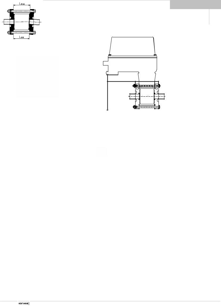
1.3.1 Position of flanges |
1.3.3 Grounding |
Install flowmeter in line with the pipe axis. Pipe flange faces must be parallel to each other, max. allowable deviation:
Lmax – Lmin ≤ 0.5 mm ≤ 0.02"
1.3.2Example: centering and sealing the primary head
The primary head is centered between the pipe flanges with the aid of the precise geometric fitting (guide collar on primary head).
Detail drawings see Sect. 1.5.
|
V |
V |
|
R |
R |
FE |
RF |
RF |
|
|
FE |
Functional ground, wire > 4 mm2 Cu. |
R |
Pipeline |
RF |
Pipe flanges |
VInterconnecting wires, bolted to the housing
•All flowmeters must be properly grounded.
•The grounding wire should not transmit any interference voltage. Therefore do not ground any other electrical device simultaneously with this conductor.
Grounding is carried out via the functional ground that is connected to the U-clamp terminal (9). See also Section 2 “Electrical connection“.
When connected to functional extra-low voltages,
24V DC, protective separation (PELV) must be ensured (VDE 0100/VDE 0106 or IEC 364/IEC 536).
Installation and operating instructions |
BATCHCONTROL |
9 |
1
1.4Installation of the primary head
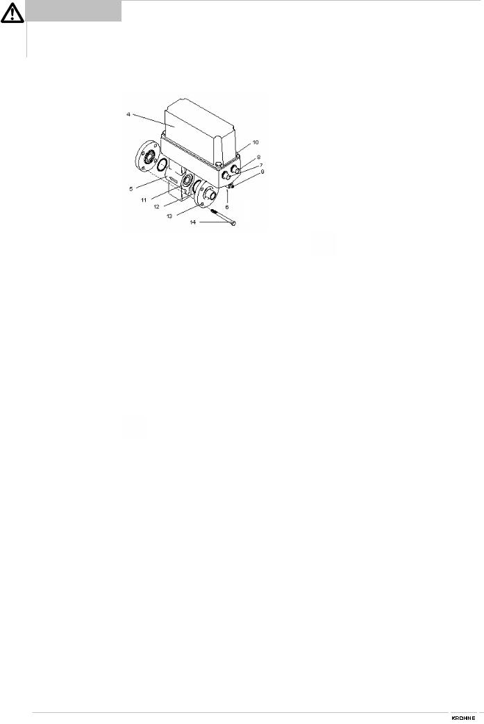
1.4.1 Device description
•BATCHCONTROL IFM 5014C
4Cover, signal converter
5Primary head
7 Connector for the six in-/outputs
8Connector for power and CAN Bus
9U-clamp terminal for functional ground 10 Fastening screws for cover
11 Locating collar, primary head
•Accessories from system manufacturer
12O-ring gasket
13Special pipe flange
14Stud bolt with lock washer, plain washer and nut
To facilitate servicing of the primary head, please note the following points:
•It must be possible to shut off the flow through the pipeline upsteam of the primary head (provide shutoff valve),
•Drain the pipe system before removing the primary head (provide drain valve),
•Support the pipeline on both sides of the flowmeter when located in a long, freely suspended section to facilitate removal of the primary head.
1.4.2 Installation of the IFM 5014C
•Position gaskets (12) in the pipe flanges.
•Type and location of gaskets as specified by the manufacturer of the filling machine (see Sect. 1.3.2 “Centering of the primary head”).
•Insert primary head (5) between the pipe flanges (13) in line with the pipe axis.
•For spacing and location of the pipe flanges, see Sect. 1.3 “Position of flanges”.
•Press pipe flanges against flowmeter.
Centering ring of pipe flanges must snap into place in the guide collar
(11)of the primary head.
•Insert stud bolts (14) with washers into the holes in the pipe flanges. Fit nuts to stud bolts with lock washer.
•Tighten stud bolts and nuts down to the metal stop symmetrically. Check all bolts after starting up the pipe system, and retighten when any leaks show.
•Connect ground conductor to U-clamp terminal (9).
•Connect power supply, CAN bus and outputs to connector plugs (7, 8) on signal converter housing (4).
See Section 2.2 and 2.3 for details of electrical connection.
10 BATCHCONTROL |
Installation and operating instructions |
1
1.5Size of connections
1.5.1 Fastening with tie bolts
All dimensions in mm (inches)
Flange-material: AISI 300 series
O-ring material: 3A standard 18-03
Meter size |
|
Centering device, pipe connection |
O-Ring |
Dimensions |
|||||
DN |
inches |
di |
D1 |
|
D2 |
h |
75 Shore |
k |
d |
2.5 |
1/10 |
6 |
25.5 |
30 |
-0.05/-0.15 |
1.5 -0.05/-0.15 |
on request |
60 |
8.5 |
|
|
(0.24) |
(1.00) |
(1.18 -0.002/-0.006) |
(0.06 -0.002/-0.006) |
on request |
(2.36) |
(0.33) |
|
4 |
1/8 |
7 |
25.5 |
30 |
-0.05/-0.15 |
1.5 -0.05/-0.15 |
on request |
60 |
8.5 |
|
|
(0.28) |
(1.00) |
(1.18 -0.002/-0.006) |
(0.06 -0.002/-0.006) |
on request |
(2.36) |
(0.33) |
|
6 |
1/4 |
9 |
25.5 |
30 |
-0.05/-0.15 |
1.5 -0.05/-0.15 |
on request |
60 |
8.5 |
|
|
(0.35) |
(1.00) |
(1.18 -0.002/-0.006) |
(0.06 -0.002/-0.006) |
on request |
(2.36) |
(0.33) |
|
10 |
3/8 |
12 |
25.5 |
30 |
-0.05/-0.15 |
1.5 -0.05/-0.15 |
on request |
60 |
8.5 |
|
|
(0.47) |
(1.00) |
(1.18 -0.002/-0.006) |
(0.06 -0.002/-0.006) |
on request |
(2.36) |
(0.33) |
|
15 |
1/2 |
14 |
25.5 |
30 |
-0.05/-0.15 |
1.5 -0.05/-0.15 |
Ø 16×5 |
60 |
8.5 |
|
|
(0.55) |
(1.00) |
(1.18 -0.002/-0.006) |
(0.06 -0.002/-0.006) |
(Ø 0.47×0.20) |
(2.36) |
(0.33) |
|
25 |
1 |
26 |
37.5 |
71.3 -0.1 |
2 +0.1 |
Ø 28×5 |
80 |
8.5 |
|
|
|
(1.02) |
(1.48) |
(2.81 –0.004) |
(0.08 +0.04) |
(Ø 1.10×0.20) |
(3.15) |
(0.33) |
|
32 |
1 1/4 |
on request |
|
|
|
|
|
|
|
|
|
|
|
|
|
|
|
|
|
40 |
11/2 |
on request |
|
|
|
|
|
|
|
|
|
|
|
|
|
|
|
|
|
DN 2.5 - 15 / 1/10“ - 1/2“
A
A |
A-A |
|
|
DN 25 / 1“ |
DN 32-40 / |
|
|
|
11/4“-11/2“ |
|
|
|
Dimensions |
|
|
|
on request |
|
|
|
|
|
|
|
|
|
Installation and operating instructions |
BATCHCONTROL |
11 |

1
1.5.2 Fastening with bolts (option)
All dimensions in mm (inches)
*Flange-material : AISI 300 series O-ring material : 3A standard 18-03
|
|
Meter size |
|
Centering device, pipe connection |
O-ring |
Screw thread (option) |
|
|||||||||
|
|
|
|
|
|
|
|
|
|
gaskets |
2× M4 |
4× M6 |
|
|||
|
|
DN |
inches |
di |
|
D1 |
|
D2 |
h |
75 Shore |
k |
d |
k |
d |
|
|
|
2.5 |
1/10 |
6 |
|
25.5 |
30 |
-0.05/-0.15 |
1.5 -0.05/-0.15 |
on request |
60 |
8.5 |
56 |
6.4 |
|
|
|
|
|
|
|
(0.24) |
|
(1.00) |
(1.18 -0.002/-0.006) |
(0.06 -0.002/-0.006) |
on request |
(2.36) |
(0.33) |
(2.20) |
(0.25) |
|
|
|
|
4 |
1/8 |
7 |
|
25.5 |
30 |
-0.05/-0.15 |
1.5 -0.05/-0.15 |
on request |
60 |
8.5 |
56 |
6.4 |
|
|
|
|
|
|
|
(0.28) |
|
(1.00) |
(1.18 -0.002/-0.006) |
(0.06 -0.002/-0.006) |
on request |
(2.36) |
(0.33) |
(2.20) |
(0.25) |
|
|
|
|
6 |
1/4 |
9 |
|
25.5 |
30 |
-0.05/-0.15 |
1.5 -0.05/-0.15 |
on request |
60 |
8.5 |
56 |
6.4 |
|
|
|
|
|
|
|
(0.35) |
|
(1.00) |
(1.18 -0.002/-0.006) |
(0.06 -0.002/-0.006) |
on request |
(2.36) |
(0.33) |
(2.20) |
(0.25) |
|
|
|
|
10 |
3/8 |
12 |
|
25.5 |
30 |
-0.05/-0.15 |
1.5 -0.05/-0.15 |
on request |
60 |
8.5 |
56 |
6.4 |
|
|
|
|
|
|
|
(0.47) |
|
(1.00) |
(1.18 -0.002/-0.006) |
(0.06 -0.002/-0.006) |
on request |
(2.36) |
(0.33) |
(2.20) |
(0.25) |
|
|
|
|
15 |
1/2 |
14 |
|
25.5 |
30 |
-0.05/-0.15 |
1.5 -0.05/-0.15 |
Ø 16×5 * |
60 |
8.5 |
56 |
6.4 |
|
|
|
|
|
|
|
(0.55) |
|
(1.00) |
(1.18 -0.002/-0.006) |
(0.06 -0.002/-0.006) |
(Ø 0.47×0.20)* |
(2.36) |
(0.33) |
(2.20) |
(0.25) |
|
|
|
|
|
|
|
|
|
|
|
|
|
|
|
|
|
|
|
|
|
|
|
|
|
|
|
|
|
|
|
|
|
|
|
|
|
|
|
|
|
|
|
|
|
|
|
|
|
|
|
|
|
|
12 BATCHCONTROL |
Installation and operating instructions |
2 Electrical connection
2.1Important information
Be sure to take note of the following information in order to ensure proper functioning of the signal converter.
Please note:
1)Overvoltage class:
In conformity with VDE 0120, equivalent to IEC 664, the compact flowmeters are designed for overvoltage category III in the supply circuits and overvoltage category II in the output circuits.
2)Safety isolation:
The compact flowmeters must be provided with an isolating facility.
Electrical connection and repairs may only be carried out by qualified personnel.
•Protect the flowmeter from direct radiant heat (e.g. hot-product tanks), insulate if necessary.
•Do not expose flowmeter to intense vibration. If necessary, support the pipeline to the right and left of the flowmeter. Level of vibration in accordance with IEC 068-2-34: below 2.2g in the 20 - 2000 Hz frequency range.
•Note information given on the instrument nameplate, voltage.
•The FE functional ground for the supply power should for measurement reasons be connected to the separate U-clamp terminal on the signal converter housing.
•When connected to a functional extralow voltage of 24 V DC, protective separation (PELV) must be ensured (VDE
0100 / VDE 0106 or IEC 364 / IEC 536 or equivalent national regulations)..
2.2 Attachment plugs
Manufacturer |
Series and type |
Description |
|
|
|
Binder |
Series 715 |
Moulded plug, straight or |
|
|
angle-entry form |
|
Series 763 |
Integrally extruded plug |
|
|
with cable in various |
|
|
lengths |
Hirschmann |
E-Series |
|
|
ELKA 4012 and |
Moulded plug, straight or |
|
ELWIKA 4012 |
angle-entry form |
|
ELKA KV 4412 |
Integrally extruded plug |
|
and ELWIKA KV |
with cable in various |
|
4412 |
lengths |
Lumberg |
RK-Series |
|
|
RKC and RKCW |
Moulded plug, straight or |
|
|
angle-entry form |
|
RKT and RKWG |
Integrally extruded plug |
|
|
with cable in various |
|
|
lengths |
Amphenol |
Series C 164 P |
Moulded plug, straight or |
|
|
angle-entry form |
|
Series C 164 P |
Integrally extruded plug |
|
compact |
with cable in various |
|
|
lengths |
Coninvers |
Series BC |
Moulded plug, straight |
|
|
form, especially suitable |
|
|
for high-interference |
|
|
environments (keyword: |
|
|
EMC) |
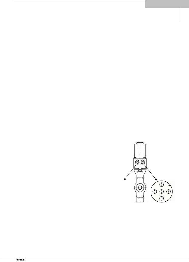
Pin-assignment and alignment of cable entry body
Installation and operating instructions |
BATCHCONTROL |
13 |
|
|
|
|
|
|
|
|
|
2 |
|
2.3 |
Power supply and CAN bus |
|
||
|
|
|
5-pin connector M12x1 for 24V DC power supply and CAN bus |
||||
|
|
|
|||||
|
|
|
|
|
|
|
Pin assignment |
|
|
|
Pin |
|
Description |
||
|
|
|
|
|
|||
|
|
|
|
|
|
|
|
|
|
|
1 |
|
ground CAN bus |
|
|
|
|
|
2 |
|
+24 V power |
|
|
|
|
|
3 |
|
ground |
|
|
|
|
|
4 |
|
CAN high level |
|
|
|
|
|
5 |
|
CAN low level |
|
|
|
|
|
|
|
|
|
|
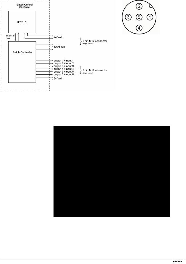
2.4Input and output
8-pin connector M12x1 for 24V DC power supply and input / output signals
Pin |
Description |
|
Pin assignment |
|
|
|
|
1 |
input / output 1 |
|
|
|
|||
2 |
input / output 2 |
|
|
3 |
input / output 3 |
|
|
4 |
input / output 4 |
|
|
5 |
input / output 5 |
|
|
6 |
input / output 6 |
|
|
7 |
+24 V power |
|
|
|
|||
8 |
ground |
|
|
|
|
|
|
2.5Block circuit diagram
The following picture shows the block circuit diagram of the BATCHCONTROL 5014C:
The individual functions of inputs and outputs are described in detail in the following chapter.
14 BATCHCONTROL |
Installation and operating instructions |
 Loading...