

Page 1
Advanced Edit
ENGLISH
OS Ver. 1.0
1E
Page 2

Page 3

Table of Contents
Table of Contents
1
Style Record mode . . . . . . . . . . . . . . . . . . . . . . . . . . . . . . . . . . . 3
The Style structure . . . . . . . . . . . . . . . . . . . . . . . . . . . . . . . . . . . . . .3
Style/Pad Import/Export . . . . . . . . . . . . . . . . . . . . . . . . . . . . . . . . .4
Entering the Style Record mode . . . . . . . . . . . . . . . . . . . . . . . . . . .4
Exit by saving or deleting changes . . . . . . . . . . . . . . . . . . . . . . . . .5
Listening to the Style while in Edit mode . . . . . . . . . . . . . . . . . . .5
List of recorded events . . . . . . . . . . . . . . . . . . . . . . . . . . . . . . . . . . .5
Main page - Record 1 . . . . . . . . . . . . . . . . . . . . . . . . . . . . . . . . . . . .6
Main page - Record 2/Cue . . . . . . . . . . . . . . . . . . . . . . . . . . . . . . . .9
Main page - Guitar Mode . . . . . . . . . . . . . . . . . . . . . . . . . . . . . . 10
Style Record procedure . . . . . . . . . . . . . . . . . . . . . . . . . . . . . . . . 14
Edit menu . . . . . . . . . . . . . . . . . . . . . . . . . . . . . . . . . . . . . . . . . . . . 16
Edit page structure . . . . . . . . . . . . . . . . . . . . . . . . . . . . . . . . . . . . 16
Event Edit: Event Edit . . . . . . . . . . . . . . . . . . . . . . . . . . . . . . . . . 17
Event Edit: Filter . . . . . . . . . . . . . . . . . . . . . . . . . . . . . . . . . . . . . . 19
Style Edit: Quantize . . . . . . . . . . . . . . . . . . . . . . . . . . . . . . . . . . . 19
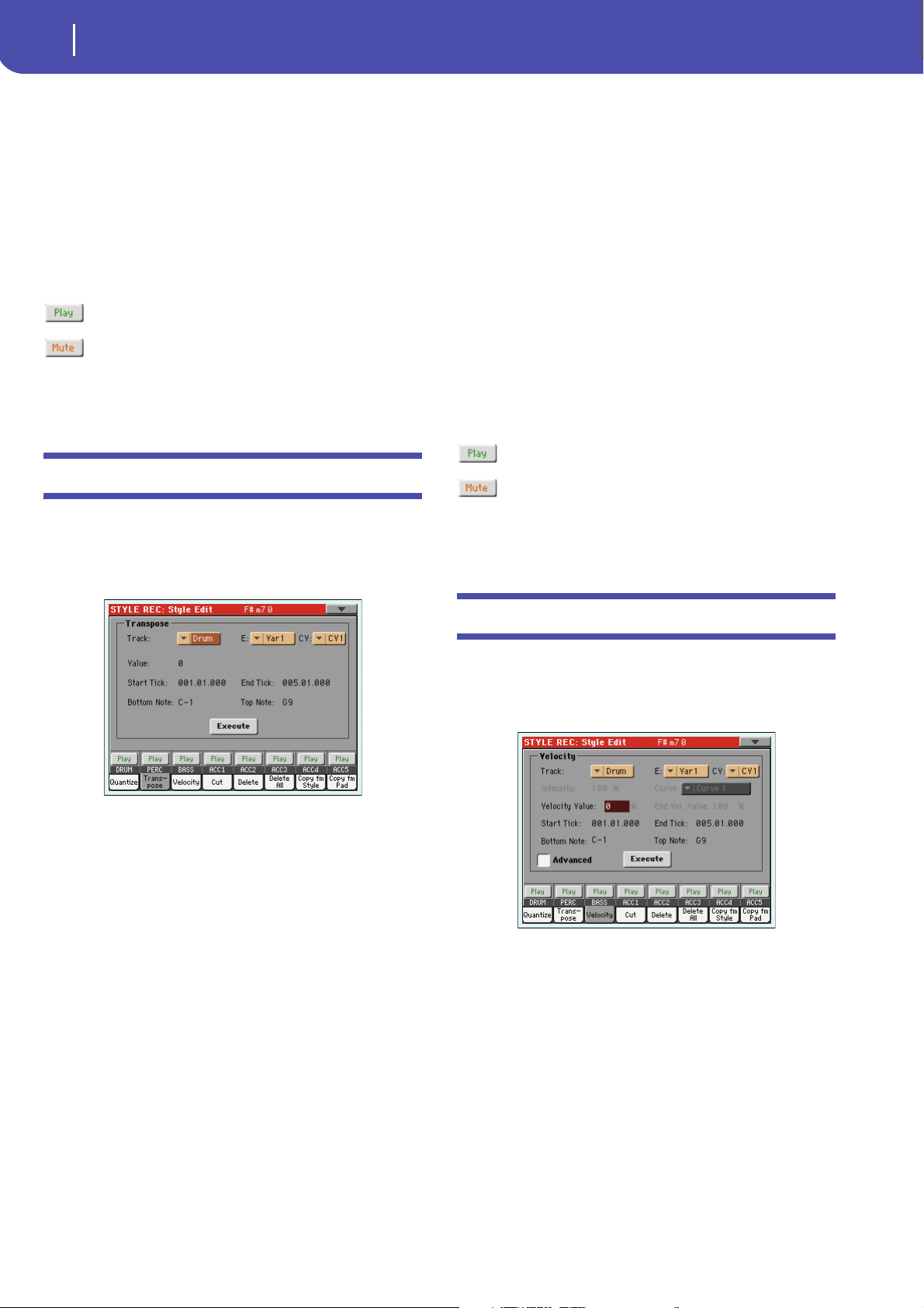
Style Edit: Transpose . . . . . . . . . . . . . . . . . . . . . . . . . . . . . . . . . . 20
Style Edit: Velocity . . . . . . . . . . . . . . . . . . . . . . . . . . . . . . . . . . . . 20
Style Edit: Cut . . . . . . . . . . . . . . . . . . . . . . . . . . . . . . . . . . . . . . . . 21
Style Edit: Delete . . . . . . . . . . . . . . . . . . . . . . . . . . . . . . . . . . . . . . 22
Style Edit: Delete All . . . . . . . . . . . . . . . . . . . . . . . . . . . . . . . . . . . 22
Style Edit: Copy from Style . . . . . . . . . . . . . . . . . . . . . . . . . . . . . 23
Style Edit: Copy from Pad . . . . . . . . . . . . . . . . . . . . . . . . . . . . . . 24
Style Element Track Controls: Sound/Expression . . . . . . . . . . 25
Style Element Track Controls: Keyboard Range . . . . . . . . . . . 26
Style Element Track Controls: Noise/Guitar . . . . . . . . . . . . . . 26
Style Element Chord Table: Chord Table . . . . . . . . . . . . . . . . . 26
Style Track Controls: Type/Trigger/Tension . . . . . . . . . . . . . . 27
Import: Import Groove . . . . . . . . . . . . . . . . . . . . . . . . . . . . . . . . 27
Import: Import SMF . . . . . . . . . . . . . . . . . . . . . . . . . . . . . . . . . . . 28
Export SMF . . . . . . . . . . . . . . . . . . . . . . . . . . . . . . . . . . . . . . . . . . 30
Page menu . . . . . . . . . . . . . . . . . . . . . . . . . . . . . . . . . . . . . . . . . . . 31
Write Style dialog box . . . . . . . . . . . . . . . . . . . . . . . . . . . . . . . . . 31
Copy Key/Chord dialog box . . . . . . . . . . . . . . . . . . . . . . . . . . . . 32
Copy Sounds dialog box . . . . . . . . . . . . . . . . . . . . . . . . . . . . . . . 32
Copy Expression dialog box . . . . . . . . . . . . . . . . . . . . . . . . . . . . 32
Copy Key Range dialog box . . . . . . . . . . . . . . . . . . . . . . . . . . . . . 33
Copy Chord Table dialog box . . . . . . . . . . . . . . . . . . . . . . . . . . . 33
Overdub Step Recording window . . . . . . . . . . . . . . . . . . . . . . . 33
Pad Record mode . . . . . . . . . . . . . . . . . . . . . . . . . . . . . . . . . . . 35
The Pad structure . . . . . . . . . . . . . . . . . . . . . . . . . . . . . . . . . . . . . 35
Entering the Pad Record mode . . . . . . . . . . . . . . . . . . . . . . . . . . 35
Exit by saving or deleting changes . . . . . . . . . . . . . . . . . . . . . . . 36
Listening to the Pad while in Record/Edit mode . . . . . . . . . . . 36
Main page - Record 1 . . . . . . . . . . . . . . . . . . . . . . . . . . . . . . . . . . 36
Main page - Guitar Mode . . . . . . . . . . . . . . . . . . . . . . . . . . . . . . 39
Pad Record procedure . . . . . . . . . . . . . . . . . . . . . . . . . . . . . . . . . 39
Edit menu . . . . . . . . . . . . . . . . . . . . . . . . . . . . . . . . . . . . . . . . . . . . 39
Edit page structure . . . . . . . . . . . . . . . . . . . . . . . . . . . . . . . . . . . . 39
Event Edit: Event Edit . . . . . . . . . . . . . . . . . . . . . . . . . . . . . . . . . 40
Event Edit: Filter . . . . . . . . . . . . . . . . . . . . . . . . . . . . . . . . . . . . . . 40
Pad Edit: Quantize . . . . . . . . . . . . . . . . . . . . . . . . . . . . . . . . . . . . 40
Pad Edit: Transpose . . . . . . . . . . . . . . . . . . . . . . . . . . . . . . . . . . . 41
Pad Edit: Velocity . . . . . . . . . . . . . . . . . . . . . . . . . . . . . . . . . . . . . 41
Pad Edit: Cut . . . . . . . . . . . . . . . . . . . . . . . . . . . . . . . . . . . . . . . . . 42
Pad Edit: Delete . . . . . . . . . . . . . . . . . . . . . . . . . . . . . . . . . . . . . . . 42
Pad Edit: Delete All . . . . . . . . . . . . . . . . . . . . . . . . . . . . . . . . . . . . 43
Pad Edit: Copy from Style . . . . . . . . . . . . . . . . . . . . . . . . . . . . . . 43
Pad Edit: Copy from Pad . . . . . . . . . . . . . . . . . . . . . . . . . . . . . . . 43
Pad Track Controls: Sound/Expression . . . . . . . . . . . . . . . . . . 44
Pad Chord Table . . . . . . . . . . . . . . . . . . . . . . . . . . . . . . . . . . . . . . 45
Import: Import Groove . . . . . . . . . . . . . . . . . . . . . . . . . . . . . . . . 45
Import: Import SMF . . . . . . . . . . . . . . . . . . . . . . . . . . . . . . . . . . . 45
Export: SMF . . . . . . . . . . . . . . . . . . . . . . . . . . . . . . . . . . . . . . . . . . 46
Page menu . . . . . . . . . . . . . . . . . . . . . . . . . . . . . . . . . . . . . . . . . . . 46
Write Pad dialog box . . . . . . . . . . . . . . . . . . . . . . . . . . . . . . . . . . 47
Sound operating mode . . . . . . . . . . . . . . . . . . . . . . . . . . . . . . 48
The MIDI channel . . . . . . . . . . . . . . . . . . . . . . . . . . . . . . . . . . . . . 48
How to select oscillators . . . . . . . . . . . . . . . . . . . . . . . . . . . . . . . . 48
Sounds, Drum Kits, Digital Drawbars . . . . . . . . . . . . . . . . . . . . 48
Main page . . . . . . . . . . . . . . . . . . . . . . . . . . . . . . . . . . . . . . . . . . . . 48
Digital Drawbars page . . . . . . . . . . . . . . . . . . . . . . . . . . . . . . . . . 50
Edit menu . . . . . . . . . . . . . . . . . . . . . . . . . . . . . . . . . . . . . . . . . . . . 51
Edit page structure . . . . . . . . . . . . . . . . . . . . . . . . . . . . . . . . . . . . 52
Basic: Sound Basic . . . . . . . . . . . . . . . . . . . . . . . . . . . . . . . . . . . . . 52
Basic: OSC Basic . . . . . . . . . . . . . . . . . . . . . . . . . . . . . . . . . . . . . . 53
Basic: Vel/Key Zone . . . . . . . . . . . . . . . . . . . . . . . . . . . . . . . . . . . 55
Basic: Damper Mode . . . . . . . . . . . . . . . . . . . . . . . . . . . . . . . . . . . 56
Basic: Damper Trigger . . . . . . . . . . . . . . . . . . . . . . . . . . . . . . . . . 57
Basic: EQ . . . . . . . . . . . . . . . . . . . . . . . . . . . . . . . . . . . . . . . . . . . . . 57
DrumKit: Sample Setup (Drum Kits) . . . . . . . . . . . . . . . . . . . . . 58
DrumKit: EQ (Drum Kits) . . . . . . . . . . . . . . . . . . . . . . . . . . . . . . 59
DrumKit: Voice Mixer (Drum Kits) . . . . . . . . . . . . . . . . . . . . . . 60
Pitch: Pitch Mod . . . . . . . . . . . . . . . . . . . . . . . . . . . . . . . . . . . . . . 61
Pitch: Pitch EG . . . . . . . . . . . . . . . . . . . . . . . . . . . . . . . . . . . . . . . . 63
Filter: Filter Type . . . . . . . . . . . . . . . . . . . . . . . . . . . . . . . . . . . . . . 64
Filter: Filter Mod . . . . . . . . . . . . . . . . . . . . . . . . . . . . . . . . . . . . . . 65
Filter: Filter LFO . . . . . . . . . . . . . . . . . . . . . . . . . . . . . . . . . . . . . . 67
Filter: Filter EG . . . . . . . . . . . . . . . . . . . . . . . . . . . . . . . . . . . . . . . 67
Amp: Amp Level/Pan . . . . . . . . . . . . . . . . . . . . . . . . . . . . . . . . . . 69
Amp: Amp Mod . . . . . . . . . . . . . . . . . . . . . . . . . . . . . . . . . . . . . . 70
Amp: Amp EG . . . . . . . . . . . . . . . . . . . . . . . . . . . . . . . . . . . . . . . . 70
LFO: LFO1 . . . . . . . . . . . . . . . . . . . . . . . . . . . . . . . . . . . . . . . . . . . 72
LFO: LFO2 . . . . . . . . . . . . . . . . . . . . . . . . . . . . . . . . . . . . . . . . . . . 74
Effects: “B” FX Config . . . . . . . . . . . . . . . . . . . . . . . . . . . . . . . . . . 74
Effects: IFX 1 . . . . . . . . . . . . . . . . . . . . . . . . . . . . . . . . . . . . . . . . . 74
Effects: Master 1 / Reverb . . . . . . . . . . . . . . . . . . . . . . . . . . . . . . . 74
Effects: Master 2 / Chorus . . . . . . . . . . . . . . . . . . . . . . . . . . . . . . 74
Effects: Master 3 . . . . . . . . . . . . . . . . . . . . . . . . . . . . . . . . . . . . . . . 74
Page menu . . . . . . . . . . . . . . . . . . . . . . . . . . . . . . . . . . . . . . . . . . . 75
Write Sound dialog box . . . . . . . . . . . . . . . . . . . . . . . . . . . . . . . . 75
Copy Oscillator dialog box . . . . . . . . . . . . . . . . . . . . . . . . . . . . . . 76
Copy Drum Kit dialog box . . . . . . . . . . . . . . . . . . . . . . . . . . . . . . 76
AMS (Alternate Modulation Source) list . . . . . . . . . . . . . . . . . . 77
Sampling operating mode . . . . . . . . . . . . . . . . . . . . . . . . . . .79
Entering and exiting the Sampling mode . . . . . . . . . . . . . . . . . 79
The Record (Sampling) procedure . . . . . . . . . . . . . . . . . . . . . . . 79
Edit menu . . . . . . . . . . . . . . . . . . . . . . . . . . . . . . . . . . . . . . . . . . . . 81
Sampling: Record . . . . . . . . . . . . . . . . . . . . . . . . . . . . . . . . . . . . . . 81
Sampling: Edit . . . . . . . . . . . . . . . . . . . . . . . . . . . . . . . . . . . . . . . . 82
Sampling: Loop Edit . . . . . . . . . . . . . . . . . . . . . . . . . . . . . . . . . . . 83
Sampling: Sampling Info . . . . . . . . . . . . . . . . . . . . . . . . . . . . . . . 84
Time Slice . . . . . . . . . . . . . . . . . . . . . . . . . . . . . . . . . . . . . . . . . . . . 85
The Time Slice procedure . . . . . . . . . . . . . . . . . . . . . . . . . . . . . . 88
The Extend procedure . . . . . . . . . . . . . . . . . . . . . . . . . . . . . . . . . 89
Multisample: Edit MS . . . . . . . . . . . . . . . . . . . . . . . . . . . . . . . . . . 89
Multisample: Key Assign . . . . . . . . . . . . . . . . . . . . . . . . . . . . . . . 90
Page menu . . . . . . . . . . . . . . . . . . . . . . . . . . . . . . . . . . . . . . . . . . . 90
Write Sample dialog box . . . . . . . . . . . . . . . . . . . . . . . . . . . . . . . 92
Advanced
Page 4

2
Table of Contents
Write MultiSample dialog box . . . . . . . . . . . . . . . . . . . . . . . . . . . 92
Write Slice dialog box . . . . . . . . . . . . . . . . . . . . . . . . . . . . . . . . . . 92
Delete Sample dialog box . . . . . . . . . . . . . . . . . . . . . . . . . . . . . . . 93
Delete Multisample dialog box . . . . . . . . . . . . . . . . . . . . . . . . . . 93
Export Sample page . . . . . . . . . . . . . . . . . . . . . . . . . . . . . . . . . . . .93
Export Multisample page . . . . . . . . . . . . . . . . . . . . . . . . . . . . . . . 94
How to merge PCM samples from various sources . . . . . . . . . 94
Voice Processor . . . . . . . . . . . . . . . . . . . . . . . . . . . . . . . . . . . . .95
Accessing the Voice Processor edit pages . . . . . . . . . . . . . . . . . 95
Voice Processor Setup: Setup . . . . . . . . . . . . . . . . . . . . . . . . . . . . 95
Voice Processor Setup: Mic Tone . . . . . . . . . . . . . . . . . . . . . . . . 96
Voice Processor Setup: Talk . . . . . . . . . . . . . . . . . . . . . . . . . . . . . 99
Voice Processor Preset: Easy Preset . . . . . . . . . . . . . . . . . . . . . . 99
Voice Processor Preset: Mixer/FX . . . . . . . . . . . . . . . . . . . . . . . 100
Voice Processor Preset: Harmony . . . . . . . . . . . . . . . . . . . . . . . 100
Voice Processor Preset: Double . . . . . . . . . . . . . . . . . . . . . . . . . 102
Voice Processor Preset: Filter & Hard Tune . . . . . . . . . . . . . . 103
Voice Processor Preset: µMod . . . . . . . . . . . . . . . . . . . . . . . . . . 104
Voice Processor Preset: Delay . . . . . . . . . . . . . . . . . . . . . . . . . . 104
Voice Processor Preset: Reverb . . . . . . . . . . . . . . . . . . . . . . . . . 105
Effects . . . . . . . . . . . . . . . . . . . . . . . . . . . . . . . . . . . . . . . . . . . . 106
Dynamic Modulation sources . . . . . . . . . . . . . . . . . . . . . . . . . . 106
Dynamics (Dynamic) . . . . . . . . . . . . . . . . . . . . . . . . . . . . . . . . .107
EQ and Filters (EQ/Filter) . . . . . . . . . . . . . . . . . . . . . . . . . . . . . 110
Overdrive, Amp models, and Mic models (OD Amp Mic) . . 118
Chorus, Flanger, and Phaser (Cho/Fln Phaser) . . . . . . . . . . . . 123
Modulation and Pitch Shift (Mod./P.Shift) . . . . . . . . . . . . . . . 131
Delay . . . . . . . . . . . . . . . . . . . . . . . . . . . . . . . . . . . . . . . . . . . . . . . 142
Reverb and Early Reflections (Reverb ER) . . . . . . . . . . . . . . . .152
Mono-Mono Serial (Mono-Mono) . . . . . . . . . . . . . . . . . . . . . .154
Double Size . . . . . . . . . . . . . . . . . . . . . . . . . . . . . . . . . . . . . . . . . .171
Vocoder . . . . . . . . . . . . . . . . . . . . . . . . . . . . . . . . . . . . . . . . . . . . .180
Factory data . . . . . . . . . . . . . . . . . . . . . . . . . . . . . . . . . . . . . . . 182
Styles . . . . . . . . . . . . . . . . . . . . . . . . . . . . . . . . . . . . . . . . . . . . . . . .182
Style Elements . . . . . . . . . . . . . . . . . . . . . . . . . . . . . . . . . . . . . . . .187
Style and Player controls . . . . . . . . . . . . . . . . . . . . . . . . . . . . . . .187
Single Touch Settings (STS) . . . . . . . . . . . . . . . . . . . . . . . . . . . .187
Sounds (Bank order) . . . . . . . . . . . . . . . . . . . . . . . . . . . . . . . . . .188
Sounds (Program Change order) . . . . . . . . . . . . . . . . . . . . . . . .201
Drum Kits . . . . . . . . . . . . . . . . . . . . . . . . . . . . . . . . . . . . . . . . . . .212
Multisamples . . . . . . . . . . . . . . . . . . . . . . . . . . . . . . . . . . . . . . . . .214
Drum Samples . . . . . . . . . . . . . . . . . . . . . . . . . . . . . . . . . . . . . . . .221
Pads . . . . . . . . . . . . . . . . . . . . . . . . . . . . . . . . . . . . . . . . . . . . . . . . .232
Effects . . . . . . . . . . . . . . . . . . . . . . . . . . . . . . . . . . . . . . . . . . . . . . .235
MIDI Setup . . . . . . . . . . . . . . . . . . . . . . . . . . . . . . . . . . . . . . . . . .237
Assignable parameters . . . . . . . . . . . . . . . . . . . . . . . . . . . . . 238
List of Assignable Footswitch / Pedal functions . . . . . . . . . . . .238
List of Assignable Slider functions . . . . . . . . . . . . . . . . . . . . . . .240
List of Assignable Switch functions . . . . . . . . . . . . . . . . . . . . . .240
List of EC5 functions . . . . . . . . . . . . . . . . . . . . . . . . . . . . . . . . . .241
Scales . . . . . . . . . . . . . . . . . . . . . . . . . . . . . . . . . . . . . . . . . . . . . . . .243
MIDI Data . . . . . . . . . . . . . . . . . . . . . . . . . . . . . . . . . . . . . . . . . 244
MIDI Controllers . . . . . . . . . . . . . . . . . . . . . . . . . . . . . . . . . . . . .244
Recognized chords . . . . . . . . . . . . . . . . . . . . . . . . . . . . . . . . . 245
Page 5
Style Record mode
The Style structure
Style Record mode
P op Balla d
Va ri ation 1
CV1
Dr um
P erc
Bass
Acc1
Acc2
Acc3
Acc4
Acc5
CV2
CV3
CV4
CV5
CV6
Va ri ation 2
Va ri ation 3
Va ri ation 4
Intro1
CV1
CV2
Intro 2
Intro 3/C.In
Fill 1
Fill 2
Break
Fill 3
Fill 4
Ending 1
Ending 2
Ending 3
3
By entering the Style Record mode, you can create your own
Styles, or edit an existing Style.
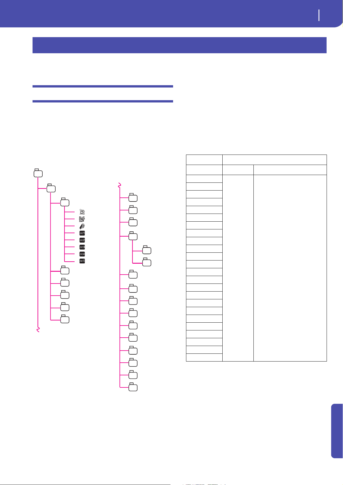
The Style structure
The term “Style” relates with music sequences automatically
played by the arranger of the Pa3X. A Style consists of a predefined number of Style Elements (E) (Pa3X features fifteen different Style Elements: Variation 1-4, Intro 1-3, Fill 1-4, Break,
Ending 1-3). When playing, these Style Elements can be selected
directly from the control panel, using the corresponding buttons.
To explain the Style structure, we can use a tree-structure, as
shown in the following diagram:
Each Style Element is made up of smaller units, called Chord
Variations (CV), but not all of them have the same number of
CVs. Variations 1-4 have up to 6 CVs each, while the other Style
Elements have only up to 2 CVs.
When you play on the chord recognition area (Lower, Upper or
Full, depending on the Chord Scanning section on the control
panel), the arranger scans the keyboard and determines which
chord you are playing. Then, depending on the selected Style
Element, it determines which Chord Variation (CV) should be
played for the scanned chord. Which Chord Variation corresponds to each scanned chord is a setting of the Style: the Chord
Variation Table. Each Style Element contains a Chord Variation
Table, whose prototype is the following:
Chord Chord Variations (CVs)
Variation 1-4 Intro 1-3, Fill 1-4, Break, Ending 1-3
Maj
6
M7
M7b5
Sus4
Sus2
M7sus4
min
m6
m7
m7b5
mM7
7
7b5
7sus4
dim
dimM7
aug
aug7
augM7
no 3rd
no 3rd, no 5th
b5
dim7
CV1 – CV6 CV1 – CV2
After deciding what CV to play, the arranger triggers the right
sequence for each track. Since each sequence is written in a particular key (for example, CMajor, GMajor or Emin), the arranger
transposes it according to the scanned chord. Notes in the
sequence are carefully transposed, to make them work fine with
all recognized chords.
Going deeper into the Style structure, we can see that each
Chord Variation is made up of Track S e q u ences, and the Pa3X
supports 8 different tracks. DRUM and PERC are used for drum
and percussion sequences, BASS for bass and ACC1-5 are for
accompaniment sequences (string, guitar, piano or other accompaniment instruments).
Advanced
Page 6
4
Style Record mode
Style/Pad Import/Export
Just to summarize, when you play a chord on the chord recognition area, the arranger determines which Style Element is used,
then determines which Chord Variation should be used for the
played chord, then Style sequences for every track of that Chord
Variation are transposed from the original chord to the recognized chord, and so on every time you play a chord.
Ordinary, Guitar and Drum tracks
There are different types of tracks (see “Track Type” on page 27),
and each of them is treated in a different way by the arranger;
• Acc (Accompaniment) and Bass tracks: When a chord is
recognized, the programmed chord notes are transposed to
a suitable scale, according to the Note Transposition
Tables ( N T T ) The NTT allows you to record just some
Chord Variations, and have all the notes play in the right
place, avoiding dissonances and transposing the pattern
notes to the notes of the recognized chord.
• Drum & and Perc (Percussion) tracks: No transposition is
applied.The original pattern plays always.
• Gtr (Guitar) tracks: When a chord is recognized, the
arranger triggers single notes, strumming and arpeggios on
a “virtual guitar”, keeping care of the way notes are played
on the guitar keyboard. Note that inside a Guitar track you
can also have some parts typical of an Acc track - a useful
addition for short “free-form” passages.
• While in Style Play mode, you can assign a single Sound to
the Style Settings (together with the other track parameters), that remains the same for all Style Elements.
Which Sounds are used depends on the status of the “Original
Style Sounds” parameter (see page 114 of the User’s Manual).
Note: When assigning a Sound in Style Play mode, the “Original
Style Sounds” is automatically turned off.
Style/Pad Import/Export
As an alternative to creating Styles on the Pa3X, you can import
a Standard MIDI Files (SMF) from your computer to a Pa3X’s
Style. See “Import: Import SMF” on page 28 and “Export SMF”
on page 30.
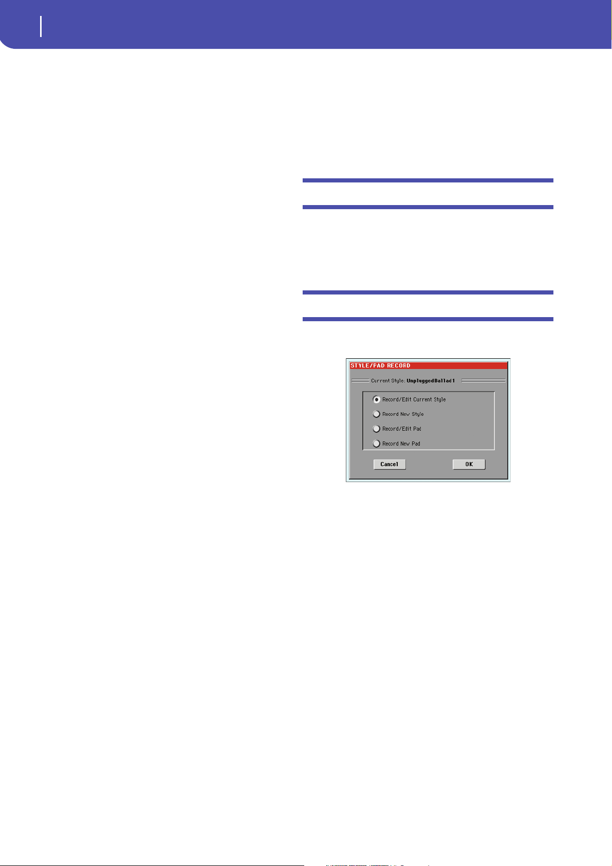
Entering the Style Record mode
While in the Style Play operating mode, press the RECORD button. The following page will appear in the display:
What to record
Recording a Style is a matter of recording tracks, inside a series
of Chord Variations, inside a series of Style Elements, inside the
Style itself.
You don’t need to record all Chord Variations for all Style Elements. It is often only needed to record just a Chord Variation
for each Style Element. Exceptions are the Intro 1 and Ending 1,
where we suggest to record both a Major and minor Chord Variations.
Pattern data vs. track data
While the Style Record mode is where you can create or edit
music patterns for the Style, track parameters (like Volume, Pan,
Octave Transpose, FX settings…) have to be edited in Style Play
mode.
• After creating or editing music patterns in Style Record
mode, save them by selecting the Write Style command
from the page menu of the Style Record mode (see “Write
Style dialog box” on page 31 of the User’s Manual).
• After editing track parameters in Style Play mode, save
them to the Style Settings by selecting the “Write Current
Style Settings” command from the page menu of the Style
Play mode (see “Write Style Settings dialog box” on
page 139 of the User’s Manual).
Sounds
There are two ways of assigning Sounds to the Style tracks.
• While in Style Record mode you can assign different
Sounds to each Style Element (see “Sounds area” on page 9
of the User’s Manual).
•Select Record/Edit Current Style to edit the current Style.
If it is a Factory Style, you may not be able to save it at the
original location (depending on the status of the “Factory
Style and Pad Protect” parameter, see page 236 of the User’s
Manual); you will select a User Style instead.
•Select Record New Style to start from a new, empty Style. A
default Style Performance will be recalled. When finished
recording, you will save the new Style onto a User Style
location. (Styles can be saved onto Factory Style locations
only when the “Factory Style and Pad Protect” parameter is
set to Off – see page 236 of the User’s Manual).
After editing the Style or Pad, please save it (see “Exit by saving
or deleting changes” below) and exit the Style/Pad Record mode.
Then, edit the Style track settings. Go to the Style Play mode,
edit the Style Settings to adjust track settings (Tempo, Volume,
Pan, FX Send… see page 119 and following in the “Style Play
operating mode” chapter of the User’s Manual) and save it by
selecting the “Write Current Style Settings” from the page menu
(see “Write Style Settings dialog box” on page 139 of the User’s
Manual).
Note: After a record or edit operation, the memory is automatically reorganized. Therefore, when you press START/STOP there is
a delay before you can actually listen to the Style. This delay is
higher with a Style containing more MIDI events.
Page 7
Style Record mode
Exit by saving or deleting changes
Note: While in Record mode, the footswitch and EC5 pedals are
disabled. On the contrary, volume/expression-type pedals can be
used.
Exit by saving or deleting changes
5
List of recorded events
The Style/Pad Record mode filters out some events that may
cause wrong operation of the Style or Pad. Here are the recorded
events, and the most important filtered-out events.
When finished editing, you can save your Style or Pad in memory, or abort any change.
•To save changes, select the “Write Style” command from the
page menu (see “Write Style dialog box” on page 31).
• To abort all changes, select the “Exit from Record” command
from the page menu, or press the RECORD button, to exit from
record and return to the main page of the Style Record mode.
Hint: Save often while recording, to avoid accidentally losing your
changes to the Style.
Listening to the Style while in Edit mode
While you are in Style/Pad Record mode, you can listen to the
selected Chord Variation or to the whole Style or Pad, depending
on the page you are in.
To select a Chord Variation, go to the Main page of the Record/
Edit mode (see “Element (Style Element)” and “Chord Var
(Chord Variation)” on page 6).
• When you are in the Main, Event Edit, Quantize, Transpose, Velocity, or Delete pages, you can listen to the
selected Chord Variation. Press START/STOP to check
how it works. Press START/STOP again to stop the playback.
• When you are in the Sounds/Expression, Keyboard Range,
Chord Table, Trigger/Tension, Delete All, Copy, Style/Pad
Element Controls or Style/Pad Control pages, you can listen to the whole Style or Pad. Press START/STOP and play
some chords to do your tests. Select any Style/Pad Element
using the control panel buttons (VARIATION 1-4, INTRO
1-3, FILL 1-4, BREAK, ENDING 1-3). Press START/STOP
again to stop the playback.
• When you are in the Guitar Mode page, you can listen to
the pattern you are programming, played in the selected
Key.
Note: While in Style Record mode, the Fingered 3 Chord Recognition mode is automatically selected.
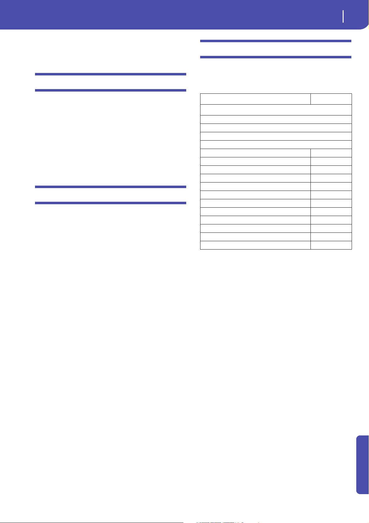
Control function CC#
Allowed
Note On
RX Noise On
Pitch Bend
Channel After Touch
Modulation 1
Breath 2
Pan 10
Expression 11
CC#12 12
CC#13 13
Damper (Hold 1) 64
Filter Resonance (Harmonic Content) 71
Low Pass Filter Cutoff (Brightness) 74
CC#80 (General Purpose #5) 80
CC#81 (General Purpose #6) 81
CC#82 (General Purpose #7) 82
Note: Some Control Change messages cannot be recorded directly
by using Pa3X integrated controls (like the Ribbon Controller).
All allowed controllers can be assigned to an Assignable Pedal/
Slider/Switch.
MIDI Control Change messaged inserted by using a software on
an external computer are imported when using the import function (“Import: Import SMF” on page 28).
Some controllers are reset at the end of the pattern.
Advanced
Page 8
6
Style Record mode
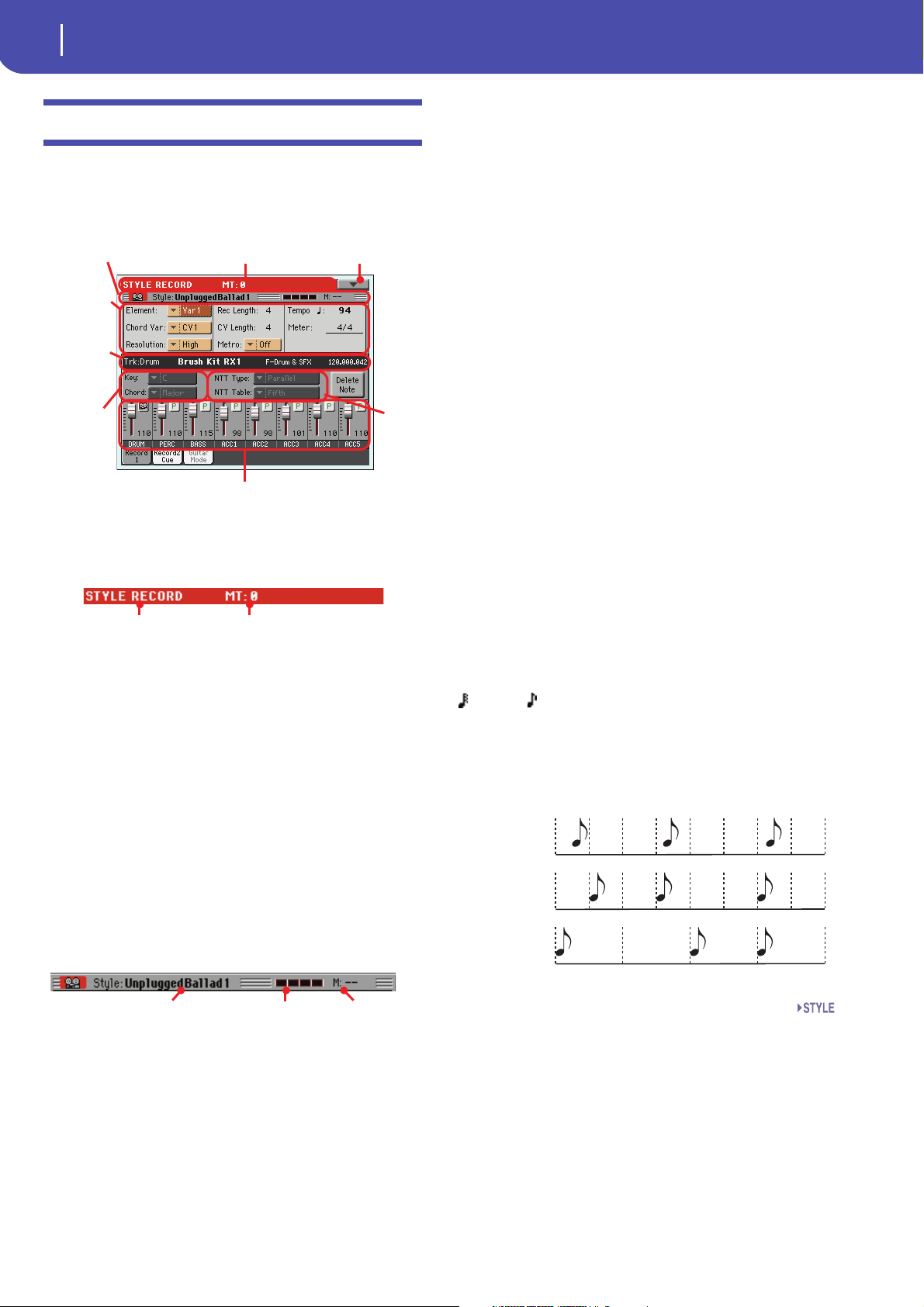
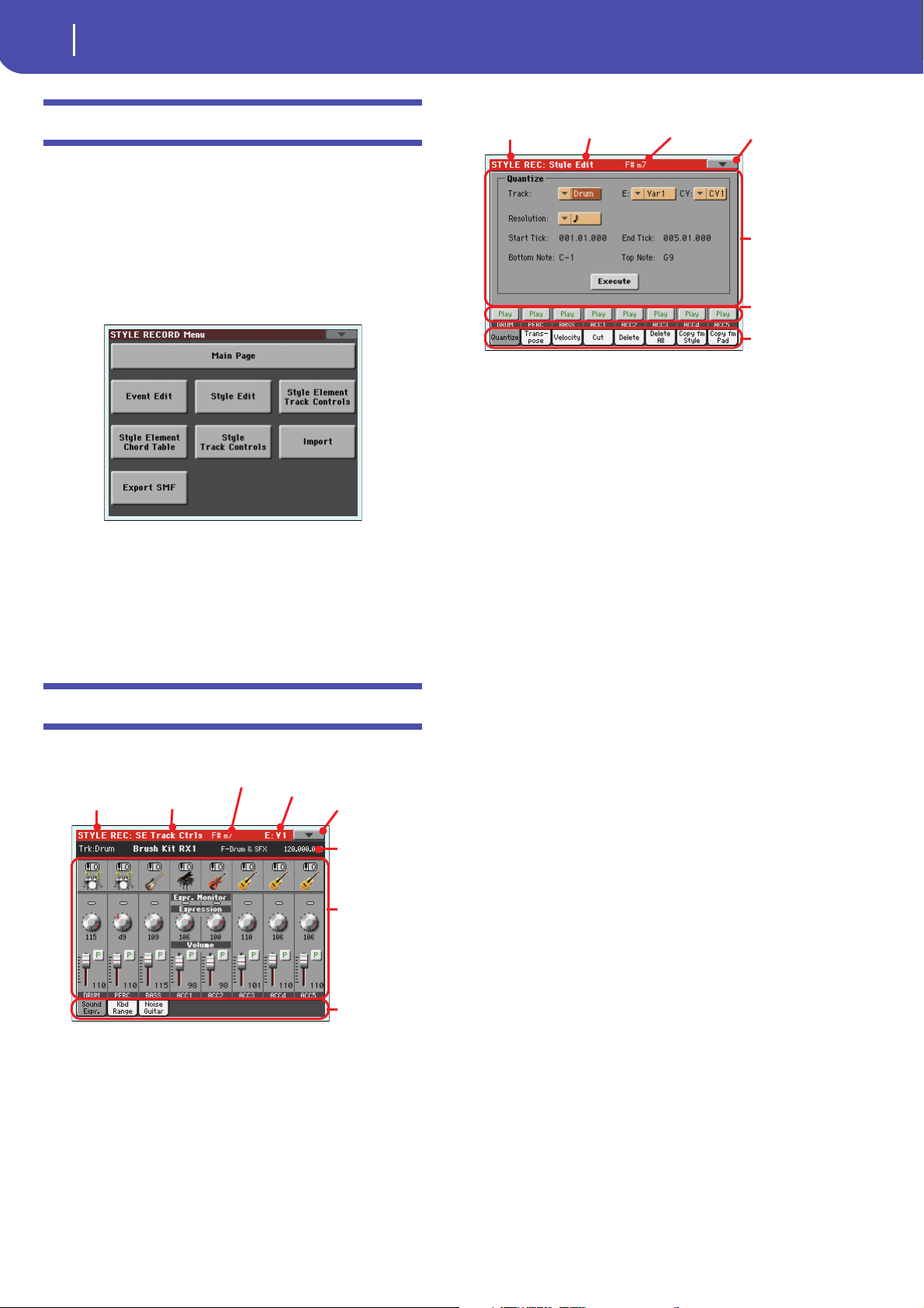
Main page - Record 1
Page header Page menu icon
Selected
track info
area
Key/
Chord
area
Track volume/status area
Recording
parameters
area
Page sub-header
NTT
area
Operating mode
name
Master Transpose (in
semitones)
Style/Pad in record/edit Beat counter Measure number
No quantiza-
tion
1/16
1/8
Main page - Record 1
After having pressed the RECORD button, and having chosen
whether you want to edit an existing Style or create a new one,
the main page of the Style Record mode appears, with the tab
“Record 1” selected.
Recording parameters area
Element (Style Element)
This parameter lets you select a Style Element for editing. Each
Style Element corresponds to a button on the control panel carrying the same name. After selecting a Style Element, select a
Chord Variation for actual editing (see below).
Var1…End3 This is the selected Style Element
Chord Var (Chord Variation)
This parameter lets you select a Chord Variation for editing,
after selecting the Style Element this Chord Variation belongs to.
Note: When this parameter and the assigned value is in small letters (cv1…cv6), the Chord Variation is empty; when it is in capitals (CV1…CV6), it is already recorded.
• If the Style Element is Var1, Var2, Var 3 or Var4, you can select
one of 6 Chord Variations to edit.
• If the Style Element is Intro1, Intro2, Intro3, Fill1, Fill2, Fill3,
Fill4, Ending1, Ending2 or Ending3, you can select one of 2
Chord Variations to edit.
Page header
This line shows the current operating mode and transposition.
Operating mode name
Name of the current operating mode.
Master transpose
Master transpose value in semitones. This value can be changed
using the TRANSPOSE buttons on the control panel.
Page menu icon
Touch this icon to open the page menu. See “Page menu” on
page 31.
Page sub-header
This area shows some performing info on the Style/Pad.
Resolution
Use this parameter to set the quantization during recording.
Quantization is a way of correcting timing errors; notes played
too soon or too later are moved to the nearest axis of a rhythmic
“grid”, set with this parameter, thus playing perfectly in time.
Note: To quantize after recording, use the Quantize function in the
Edit section (see “Style Edit: Quantize” on page 19).
High No quantization applied.
(1/32)… (1/8)
Grid resolution, in musical values. For example,
when you select 1/16, all notes are moved to the
nearest 1/16 division. When you select 1/8, all
notes are moved to the nearest 1/8 division. A ‘3’
after the quantization value means triplet.
Style in record/edit
Name of the Style currently in edit or record.
Beat counter
This indicator shows the current beat inside the current measure.
Measure number
Current measure you are recording.
Rec Length (Recording Length)
This parameter sets the recording length (in measures) of the
selected track. Its value is always equal to, or a divider of, the
Chord Variation Length (see next parameter).
This is not the total length of the Chord Variation, but just of the
current track. For example, you may have a Chord Variation
eight measures long, with a drum pattern repeating each two
measures. If so, set the CV Length parameter to “8”, and the Rec
Length parameter to “2” before starting recording the Drum
track. When playing back the Style, saving it or executing any
edit operation on the Style, the 2-measures pattern will be
extended to the full 8-measures length of the Chord Variation.
Page 9

7
Style Record mode
Main page - Record 1
Track name
Sound name
Sound bank
Program Change
Wa r n in g : If you assign CV Length a value lower than Rec Length,
the value of Rec Length is not immediately updated in the display.
Therefore, you are still free of changing the value of CV Length,
before the measures exceeding its value are deleted (see warning in
“CV Length (Chord Variation Length)” below).
However, if you press START/STOP to begin recording, the real
Rec Length value is changed to the new one, even if the display still
shows the old value.
For example, you may have CV Length = 4 and Rec Length = 4. If
you set CV Length to 2, and press START/STOP to begin recording, Rec Length is still shown as 4, but it is in reality set to 2, and
recording will cycle for just 2 measures. After you press START/
STOP to stop recording, Rec Length is updated to 2, and all measures after the second measure are deleted.
CV Length (Chord Variation Length)
This parameter sets the total length (up to 32 measures) for the
selected Chord Variation. When playing a Style, this will be the
length of the accompaniment pattern, when the chord corresponding to the Chord Variation is recognized on the keyboard.
Wa r n in g : If you reduce the Chord Variation Length after recording, any measure after the selected length will be deleted. Be very
careful when setting the CV Length to a lower value after recording! If it happens, we suggest to exit from record without saving
(see “Exit from Record” on page 31).
Selected track info area
This line lets you see the Sound assigned to the selected track.
Track name
Name of the selected track.
Drum…Acc5 Style track.
Sound name
Sound assigned to the selected track. The triangle means you can
touch the name to open the Sound Select window, and select a
different Sound.
Sound bank
Bank the selected Sound belongs to.
Program Change
Program Change number sequence (Bank Select MSB, Bank
Select LSB, Program Change).
Metro (Metronome)
This is where you can set the metronome.
Off No metronome click will be heard during record-
ing. In any case, a one-bar precount will be played
before starting recording.
On1 Metronome on, with a one-bar precount before
starting recording.
On2 Metronome on, with a two-bar precount before
starting recording.
Te mp o
Select this parameter to use TEMPO controls to set the tempo.
Hint: You can always change the Tempo, when other parameters
are selected, by keeping the SHIFT button pressed, and rotating the
DIAL.
Note: When recording Tempo, old data is always replaced by the
new data.
Note: The actual Tempo of the Style will be the one shown when
saving the Style Performance in Style Play mode (see “Current
Tempo” on pag e 1 1 2 of the User’s Manual).
Meter
This is the meter (time signature) of the Style Element. You can
edit this parameter only when the Style Element is empty, i.e.
before you begin recording anything.
Key/Chord area
Key/Chord
This parameter pair allows you to define the track’s original key
and chord type, for the current Chord Variation. When in Style
Play mode, this chord will be played back exactly as it was
recorded, without any NTT processing (see above).
To record just one Chord Variation for a Style Element, the suggested original key/chord is “maj7” (with NTT = i-Series). Be
very careful to play the 7th+ note (i.e., with a “Cmaj7th” key/
chord, the B), to avoid the lack of notes, or a bad NTT conversion when playing different chords.
Note: To conform to Korg specifications, it is advisable to record
both the “Major” and “minor” Chord Variations for the Intro 1 and
Ending 1 Style Elements.
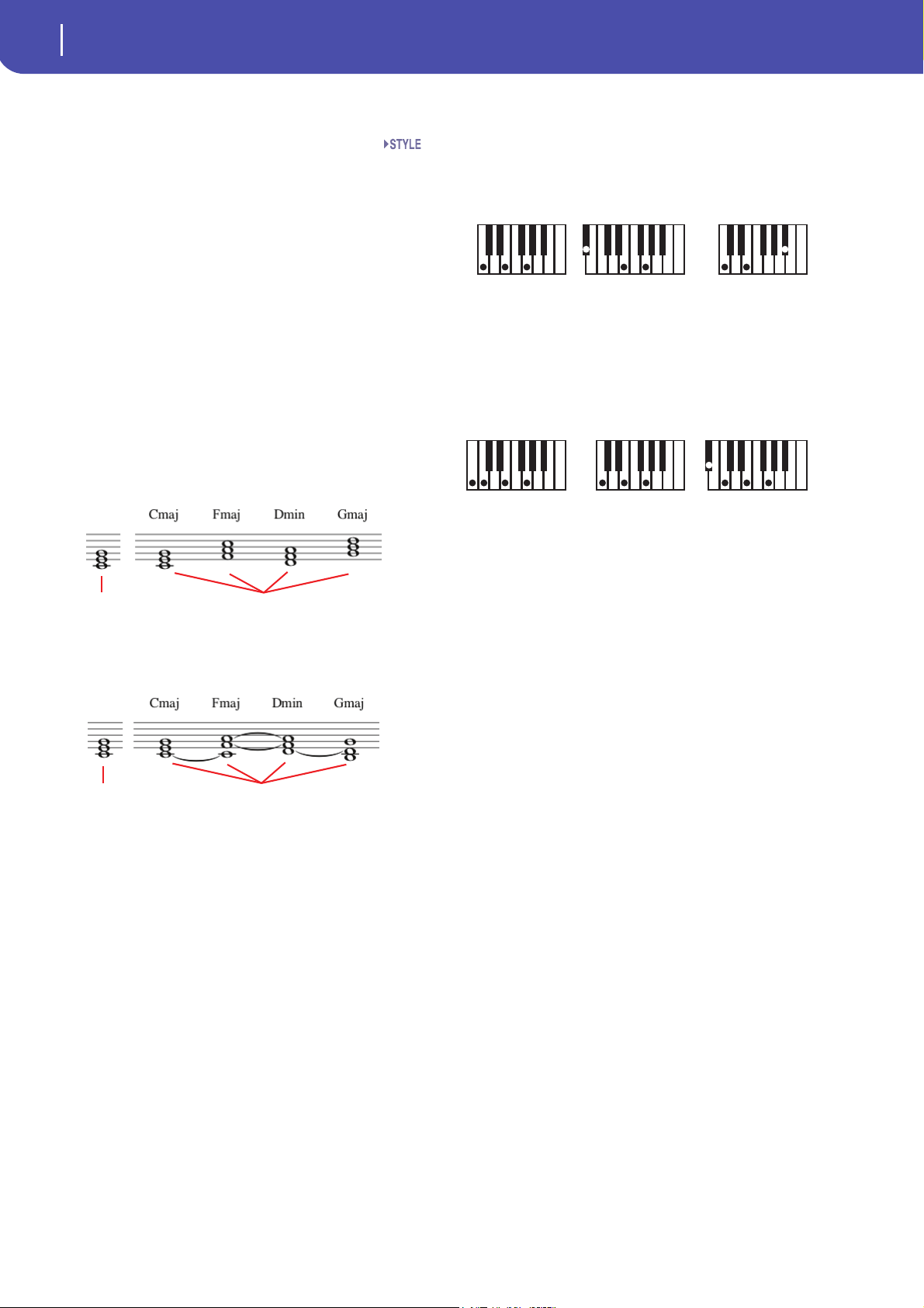
When you select a track, the original key/chord assigned to the
selected track will be shown. All recorded tracks will play back
on that key/chord. For example, if the original key/chord for the
Acc1 track is A7th, when selecting the Acc1 track all the remaining tracks will play on the A7th key/chord.
In the example above, you will record the Acc1 track in the
AMajor key, with notes pertaining to the A7th scale. This exact
pattern will be recalled, when an A7th chord will be recognized.
Note: This does not apply to Guitar Mode, relying on a different
rule. See “Main page - Guitar Mode” on page 10 for more infomation.
Advanced
Page 10
8
Style Record mode
Main page - Record 1
as written as played back
as written as played back
As recorded with
NTT = Root or 5t h
(Key/Chord = CMaj )
When you play a CM7
with NTT = Root
When you play a CM7
with NTT = 5th
As recorded with
NTT = i-Series
(Key/Chord = CM7 )
When you play a CMaj
with NTT = i-Series
When you play a C7
with NTT = i-Series
NTT Area
NTT Type/Table
NTTs (Note Transposition Tables) are the sophisticated algorithms that allow Korg arrangers to convert recognized chords
into musical patterns. The Note Transposition Table (NTT)
determines how the arranger will transpose pattern notes, when
a chord is recognized that does not exactly match the original
chord of a Chord Variation. For example, if you only recorded a
Chord Variation for the CMaj chord, when a CMaj7 is recognized on the keyboard the arranger must transpose some notes
to create the missing 7th.
Note: These parameters cannot be selected with Drum or Percussion tracks, and are therefore greyed out.
Note: NTT parameters are separately programmed for each track
of the Style Element.
There are two general types of NTTs:
•When Parallel types are selected, notes are transposed inside
the area set by the Wrap Around parameter. These tables are ideally suited to melody parts.
•When Fixed types are selected, the arranger moves as few notes
as possible, making legato lines and chord changes more natural.
They are ideally suited to chord tracks (strings, piano etc…).
Note: To conform to Korg specifications, it is advisable to set the
NTT to “No Transpose” on the Intro 1 and Ending 1.
Parallel/Root The root note (in CMaj = C) is transposed to the
missing notes.
Parallel/Fifth The 5th note (in CMaj = G) is transposed to the
missing notes.
Parallel/i-Series
All original patterns must be programmed on the
“Maj7” or “min7” chords. When loading old Korg
i-Series Styles, this option is automatically
selected.
Parallel/No Transpose
The chord is not modified, and is moved to the
new key unchanged. The pattern plays exactly the
recorded notes, and is moved to the new key as is.
This is the standard setting of Intro 1 and Ending
1 in Korg’s original Styles (where a chord progression is usually recorded, and should remain
unchanged in any key).
Fixed/Chord This table moves as few notes as possible, making
legato lines and chord changes more natural. It is
ideally suited to chord tracks (strings, piano
etc…). Contrary to the Parallel mode, the programmed chord is not transposed according to
the Wrap Around parameter, but always stays
around its original position, looking for common
notes between the chords.
Fixed/No Transpose
The programmed notes can only be transposed
by the Master Transpose. They are never transposed when chords are changed.
Page 11
Style Record mode
Main page - Record 2/Cue
Delete Note button
PA D
Sounds area
Cue area
Octave transpose icon
Sound bank’s icon
Use this command to delete a single note or a single percussive
instrument from a track. For example, to delete a snare, keep the
D2 note (corresponding to the snare) pressed.
1. Select a track.
2. Touch the “Delete Note” button, and keep it pressed.
3. Press START/STOP to start the Style.
4. When you reach the passage containing the note to be
deleted, play the note on the keyboard. Keep it pressed, up
to the last note to be deleted.
5. When finished, release the Delete button and the note to be
deleted, and press START/STOP again to stop the Style.
Note: If the note is at the beginning of the pattern, press the
note before starting the Style.
Tracks volume/status area
9
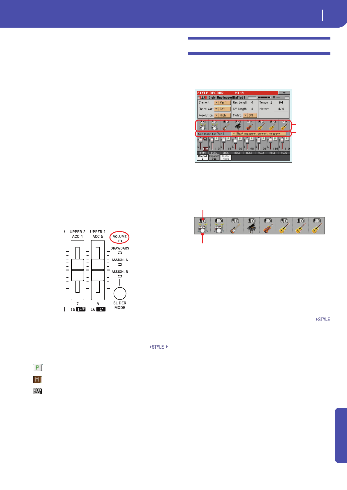
Main page - Record 2/Cue
While in the main page, touch the “Record 2/Cue” tab to see this
page. Most parameters in this page are the same as in “Main page
- Record 1”. In addition, here you can see and select Sounds for
each Style track, and the Cue mode for the Style Element.
Virtual sliders
Each virtual slider in the display corresponds to an Assignable
Slider on the control panel. Use the Assignable Sliders to change
each value, provided the VOLUME LED (over the SLIDER
MODE button) is turned on. This LED status depends on the
last selected Performance, but can be changed anytime by using
the SLIDER MODE button.
As an alternative, touch the track’s area to select a track, and use
VALUE controls to change the value (or touch and drag it in the
display).
Track st atus icons
Status of tracks. Touch this icon to change the status.
Play status. The track can be heard.
Mute status. The track cannot be heard.
Sounds area
This area lets you see Sounds and octave transposition for the
eight Style tracks.
Octave transpose icon
Non editable. This indicator shows the track’s octave transposition. Tracks will be recorded with the selected octave transposition. To change this value, use the UPPER OCTAVE buttons, or
go to the “Mixer/Tuning: Tuning” edit page in the Style Play
mode (see page 123 of the User’s Manual). Save this value to the
Style Settings.
Sound bank’s icon
This picture illustrates the bank the current Sound belongs to.
Touch an icon a first time to select the corresponding track
(detailed information are shown on the Selected Track Info area,
see the “Record 1” page above). Touch it a second time to open
the Sound Select window.
Note: These Sounds can be replaced by Sounds selected by a Performance, provided the “Original Style Sounds” parameter is left
unchecked in Style Play mode (see page 114 of the User’s Manual).
Track na mes
Under the sliders, a label for each track is shown.
Drum…Acc5 Shown Style tracks.
Record status. After starting recording, the track
will receive notes from the keyboard and the
MIDI IN connector.
Advanced
Page 12
10
Style Record mode
Main page - Guitar Mode
Cue area
Cue mode for [Style element]
This parameter lets you decide how the current Style Element
will enter after it has been selected. This setting is only available
for the ‘Variation’ and ‘Fill’ Style Elements.
Immediate, first measure
The Style Element enters immediately, and begins
from the first measure. Only available on Fills.
Immediate, current measure
The Style Element enters immediately, and begins
from the current measure. Only available on Fills.
Next measure, first measure
The Style Element enters at the beginning of the
next measure, and begins from the first measure
of the new pattern. Available on both Fills and
Va ri at i on s .
Next measure, current measure
The Style Element enters at the beginning of the
next measure, and begins from the current measure. Only available on Variations.
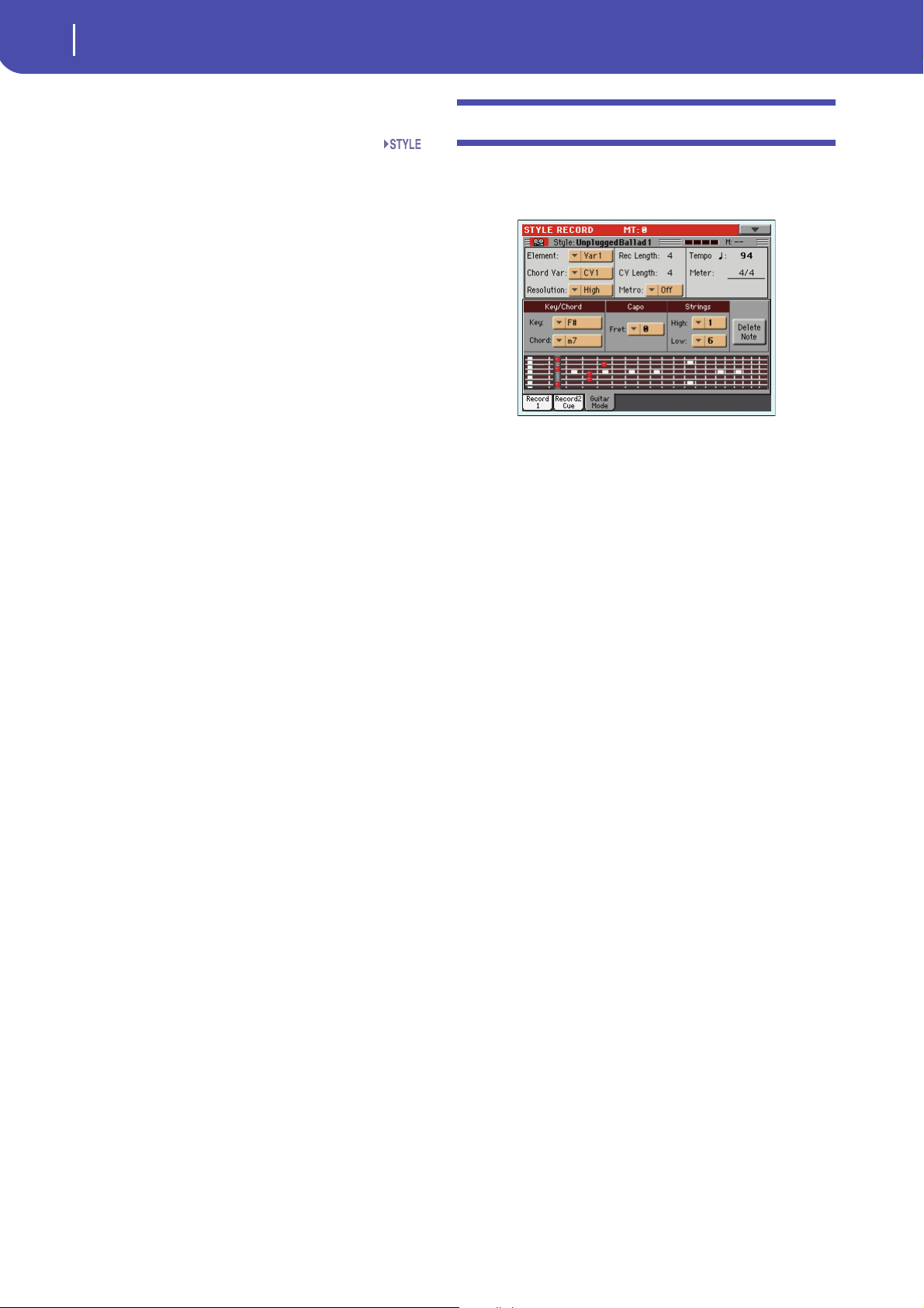
Main page - Guitar Mode
While in the main page, and a Guitar track has been selected,
touch the “Guitar Mode” tab to see this page. This is where you
can access Guitar Mode programming:
Note: To access this page, a Guitar track must first be selected (see
“Track Type” on page27 of the User’s Manual). Otherwise, the
Guitar Mode tab will remain grey (not selectable).
Note: When programming a Guitar track from an external
sequencer, you must be sure the Guitar tracks is associated to the
right channel. Go to the Global > MIDI > MIDI IN Channels page,
and assign the corresponding Style track (usually Acc1 ~ Acc5) to
the same channel of the Guitar track on the external sequencer.
Then, go to the Style Record > Style Track Controls > Type/Tension/Trigger page, and set the track as a track of type “Gtr” (see
“Track Type” on page 27 of the User’s Manual).
Guitar Mode allows to easily create realistic rhythm guitar parts,
without the artificial, unmusical playing typical of MIDI programming of guitar parts. Just record a few measures, and you
will end up with realistic rhythm guitar tracks, where each chord
is played according to its real position on the guitar, and not generated by simply transposing a written pattern.
Recording overview
Recording a Guitar track is unlike recording the other tracks,
where you play exactly all the notes of a melody line or all the
chords of an accompaniment part. With Guitar tracks you can:
a) play the keys corresponding to the strumming modes,
b) play an arpeggio using the six keys corresponding to the six
guitar strings (and the special keys corresponding to the root
and fifth notes),
c) play RX Noises to add realism to the pattern,
d) add regular patterns, for short melodic passages without wast-
ing an Acc track,
e) use the finest MIDI programing to select Chord Shapes, and
recreate any nuance of a guitar performance.
The following sections describe the various control keys available for this guitar simulation.
Page 13
11
Style Record mode
Main page - Guitar Mode
Pa3X 61
Pa3X 76
Full Up
Full D own Mute
Full Up Mute
Full Down
Full Down Mute Body
Full D own Slow Mute
Full Up Slow
Full D own
Slow
Up 4-Strings
Down 4-Strings
Down Mute 4-Strings
Up Mute 4-Strings
IV String (D)
V String (A) II String (B)
Down/Up
4-Strings
Full Down/Up
All Mute
VI String (E)
III String (G)
I String (e)
Recognized
Chord Root
Recognized Chord
Fifth
Power Ch ord
Pa3X 61
Pa3X 76
RX Noises
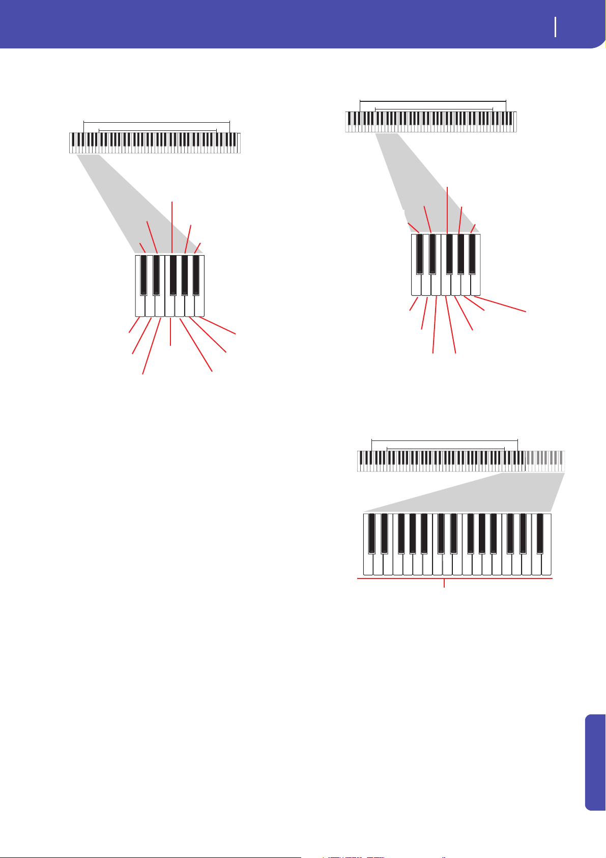
Recording strumming types
The octave from C1 to B1 is devoted to selecting a strumming
type. By pressing these keys, you play fast strumming samples:
key; with them, you can always play the lowest notes of an arpeggio. This octave also includes an ‘all mute’ key (F#):
Pa3X 76
Pa3X 61
Recording single strings
The octave from C2 to B2 is devoted to selecting a single string
(or more than one) for playing arpeggios or power chords. You
can either play a free arpeggio with the six guitar chords
assigned to the C~A keys, or play one of the faster sampled
arpeggios on the higher keys. The root note is always available
on the C# key, while the fifth note is always assigned to the D#
Recording RX Noises
Further on, the upper octaves are used to trigger RX Noises:
Selecting a Capo
Together with strumming types, single strings and RX Noises,
you can choose a Capo (capotasto). Note that this might prevent
some single strings to sound, depending on the composed
chord. You can always see with strings are playing and which are
not, as described in the “Diagram” section below.
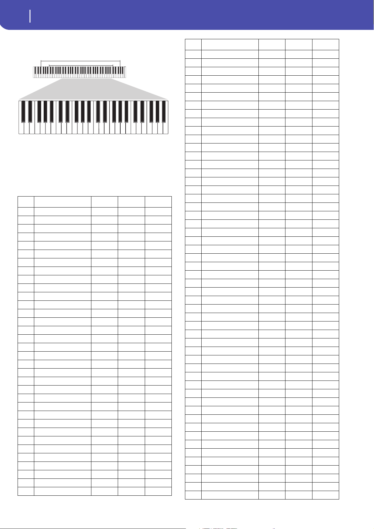
Recording a regular pattern
Together with strums and arpeggios, you can record regular patterns, exactly as if the track was of Acc type (see “Track Type” on
page 27 of the User’s Manual). This will save an Accompaniment
track, when all you need is just to record some short melodic
passages (for example, the closing of a strumming pattern).
Advanced
Page 14
12
Style Record mode
Main page - Guitar Mode
Pa3X 61
Pa3X 76
You can record the pattern by playing it in the range shown by
the diagram.
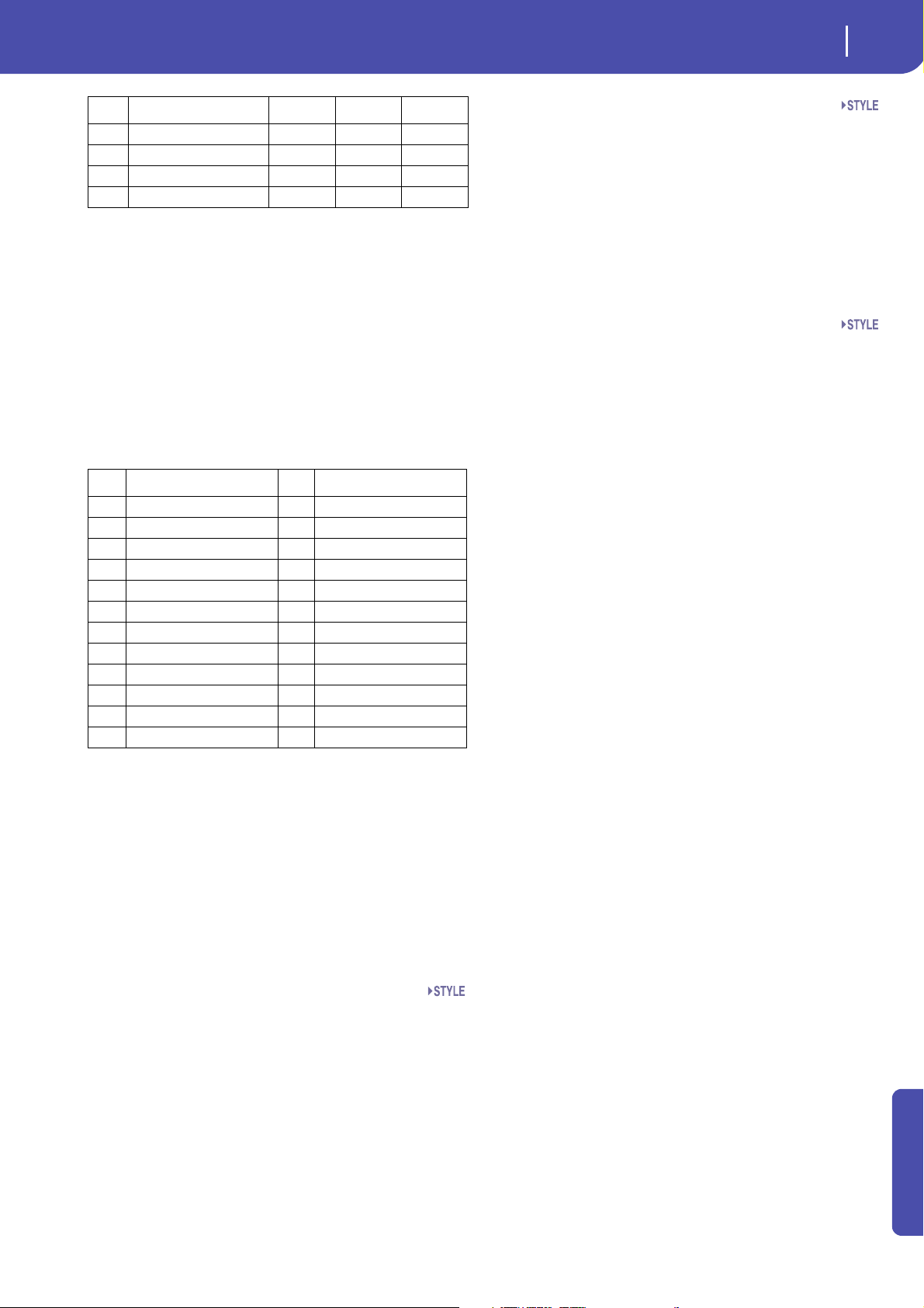
Recording a Chord Shape
You can finely choose Chord Shapes by using MIDI messages.
When you play a C0 note with the velocity value shown in the
following table, a chord is played in a particular position and on
a certain number of strings.
Vel. Range from Str. to Str. Position
06 Strings I VI 0
16 Strings I VI 0
26 Strings I VI 1
36 Strings I VI 2
46 Strings I VI 3
56 Strings I VI 4
66 Strings I VI 5
7 5 Strings Bass II VI 0
8 5 Strings Bass II VI 1
9 5 Strings Bass II VI 2
10 5 Strings Bass II VI 3
11 5 Strings Bass II VI 4
12 5 Strings Bass II VI 5
13 5 Strings Treble I V 0
14 5 Strings Treble I V 1
15 5 Strings Treble I V 2
16 5 Strings Treble I V 3
17 5 Strings Treble I V 4
18 5 Strings Treble I V 5
19 4 Strings Bass III VI 0
20 4 Strings Bass III VI 1
21 4 Strings Bass III VI 2
22 4 Strings Bass III VI 3
23 4 Strings Bass III VI 4
24 4 Strings Bass III VI 5
25 4 Strings Middle II V 0
26 4 Strings Middle II V 1
27 4 Strings Middle II V 2
28 4 Strings Middle II V 3
29 4 Strings Middle II V 4
30 4 Strings Middle II V 5
31 4 Strings Treble I IV 0
32 4 Strings Treble I IV 1
33 4 Strings Treble I IV 2
Vel. Range from Str. to Str. Position
34 4 Strings Treble I IV 3
35 4 Strings Treble I IV 4
36 4 Strings Treble I IV 5
37 3 Strings Bass IV VI 0
38 3 Strings Bass IV VI 1
39 3 Strings Bass IV VI 2
40 3 Strings Bass IV VI 3
41 3 Strings Bass IV VI 4
42 3 Strings Bass IV VI 5
43 3 Strings MiddleBas III V 0
44 3 Strings MiddleBas III V 1
45 3 Strings MiddleBas III V 2
46 3 Strings MiddleBas III V 3
47 3 Strings MiddleBas III V 4
48 3 Strings MiddleBas III V 5
49 3 Strings MiddleTreble II IV 0
50 3 Strings MiddleTreble II IV 1
51 3 Strings MiddleTreble II IV 2
52 3 Strings MiddleTreble II IV 3
53 3 Strings MiddleTreble II IV 4
54 3 Strings MiddleTreble II IV 5
55 3 Strings Treble I III 0
56 3 Strings Treble I III 1
57 3 Strings Treble I III 2
58 3 Strings Treble I III 3
59 3 Strings Treble I III 4
60 3 Strings Treble I III 5
61 2 Strings Bass V VI 0
62 2 Strings Bass V VI 1
63 2 Strings Bass V VI 2
64 2 Strings Bass V VI 3
65 2 Strings Bass V VI 4
66 2 Strings Bass V VI 5
67 2 Strings MiddleBas IV V 0
68 2 Strings MiddleBas IV V 1
69 2 Strings MiddleBas IV V 2
70 2 Strings MiddleBas IV V 3
71 2 Strings MiddleBas IV V 4
72 2 Strings MiddleBas IV V 5
73 2 Strings Middle III IV 0
74 2 Strings Middle III IV 1
75 2 Strings Middle III IV 2
76 2 Strings Middle III IV 3
77 2 Strings Middle III IV 4
78 2 Strings Middle III IV 5
79 2 Strings MiddleTreble II III 0
80 2 Strings MiddleTreble II III 1
81 2 Strings MiddleTreble II III 2
82 2 Strings MiddleTreble II III 3
83 2 Strings MiddleTreble II III 4
84 2 Strings MiddleTreble II III 5
85 2 Strings Treble I II 0
86 2 Strings Treble I II 1
Page 15
13
Style Record mode
Main page - Guitar Mode
Vel. Range from Str. to Str. Position
87 2 Strings Treble I II 2
88 2 Strings Treble I II 3
89 2 Strings Treble I II 4
90 2 Strings Treble I II 5
Choosing a Key/Chord for Intro 1 and Ending 1
The pattern is recorded in the key indicated by the Key/Chord
pair of parameters. However, this parameter is only used for
playback by the Intro 1 and Ending 1 Style Elements. All other
Style Elements will be played back according to the recognized
chord.
With Intro 1 and Ending 1 (both Chord Variation 1 and 2) you
can also prefer to enter a chord progression, to be played on the
lowest MIDI octave (C-1 ~ B-1). Chord types are inserted by
using velocity values, as shown in the following table:
Vel. Chord Type Vel. Chord Type
1 Major 2 Major 6th
3 Major 7th 4 Major 7th flatted 5th
5 Suspended 4th 6 Suspended 2nd
7 Major 7th suspended 4th 8 Minor
9 Minor 6th 10 Minor 7th
11 Minor 7th flatted 5th 12 Minor major 7th
13 Dominant 7th 14 7th flatted 5th
15 7th suspended 4th 16 Dimished
17 Diminished major 7th 18 Augmented
19 Augmented 7th 20 Augmented major 7th
21 Major w/o 3rd 22 Major w/o 3rd and 5th
23 Flatted 5th 24 Diminished 7th
Capo - Fret
A capo (from the Italian “capotasto”, “head of fingerboard”) is a
movable bar attached to the fingerboard of the guitar, to uniformly raise the pitch of all the strings. Its use makes the strings
shorter, therefore changing the timbre and position of the chords
(but not its shape).
0 Open string – no capo.
I…X Position of the capo over the fingerboard (i.e., “I”
corresponds to the first fret, “II” to the second
one, and so on).
Strings - High/Low
Use this pair of parameters to choose the strings the pattern will
be played on.
1…6 Position of the capo over the fingerboard (i.e., “I”
corresponds to the first fret, “II” to the second o
Diagram
The diagram shows how a chord would be composed on the fingerboard. Here is the meaning of the various symbols:
Red dot Fingered string (i.e., played note).
White dot Fifth, playing on the D#2 key.
X Non played or muted note.
Light grey bar Barré (a finger crossing all the strings, like a
mobile capo).
Dark grey bar Capo.
Playing back the pattern
When in Stye Play mode, the recorded Guitar pattern is transposed according to the chord recognized on the keyboard. The
way it is transposed depends on the programmed pattern, with
the chosen positions, strumming mods, etc…
Guitar mode parameters
Here is a detailed description of the parameters of the Guitar
Mode page.
Key/Chord
This parameter pair allows you to define the track’s original key
and chord type. This parameter works in a different way than the
other tracks. While with other tracks this is always the reference
key used for NTT transposition, with Guitar tracks there is a difference, whether you are recording a Chord Variation contained
in an Intro 1 or Ending 1 Style Element, or any other Chord
Va r ia t i on :
• With Intro 1 and Ending 1, this chord will be used as the
reference key for the chord progression.
• With all the other Chord Variations, this chord will be used
only for listening during recording. During playback in
Style Play mode, the chord will follow chord recognition.
Advanced
Page 16
14
Style Record mode
Style Record procedure
Style Record procedure
There are two different methods for recording a Style: Realtime
and Step.
• Realtime Recording allows you to record Style patterns in
realtime.
• Step Recording allows you to create a new Style by entering
single notes or chords in each track. This is very useful
when transcribing an existing score, or needing a higher
grade of detail, and is particularly suitable to create drum
and percussion tracks.
In addition, you can program a Style on a personal computer,
and then import it via the Import function (see “Import: Import
SMF” on page 28).
Preparing to record
1. If you like to edit an existing Style, select that Style.
2. Press the RECORD button to enter the Style Record mode.
You are prompted to select either the Current Style, or a
New Style.
Select “Record/Edit Current Style” if you want to edit the
current Style, or make a new Style starting from an existing
one. Select “Record New Style” if you want to start from
scratch with an empty Style.
3. After you select your preferred option, the main page of the
Style Record mode will appear.
4. Select the Element (Style Element) and Chord Var (Chord
Variation) parameters, to select the Chord Variation to be
recorded/edited.
Note: For more information on the Style Elements and Chord
Variations, and the Style structure in general, see “The Style
structure” on page 3.
5. Use the Rec Length (Recording Length) parameter to set
the length (in measures) of the pattern to record.
6. Use the Meter parameter to set the Style Element’s meter
(time signature).
Note: You can edit this parameter only if you selected the
“Record New Style” option when entering the Record mode,
or when editing an empty Style Element.
7. Select the Tempo parameter and set the tempo.
8. Touch the Record 2 tab to see the Sounds area. Here you
can assign the right Sound to each Style track. You cannot
select Digital Drawbars Sounds. (For more details, see
“Sounds area” on page 9).
9. If needed, set the Octave Transpose for each track. Note:
The Octave Transpose will affect only the notes coming from
the keyboard, and not from the arranger.
10. At this point, if you want to do a Realtime Recording go on
reading “Realtime Record procedure” below. Otherwise, if
you prefer to do a Step Record, jump to “Step Record procedure” on page 15.
Realtime Record procedure
1. Select the track to record. Its status icon will turn to
‘Record’. (For more details, see “Tracks volume/status area”
on page 9).
Note: When entering the Record mode, a track is already
in Record status. When you press START/STOP after
entering the Record mode, you can immediately start
recording.
If you like, you can try your part before recording:
•Mute the track, by repeatedly touching its icon status,
until the (Mute) status icon appears.
• Press START/STOP to let any recorded track play back,
and practice on the keyboard.
• When you have finished practicing, press START/STOP
to stop the arranger, and unmute the track by repeatedly
touching its icon status, until the (Record) status icon
appears again.
2. While the shown status icon is Record, press START/STOP
to begin recording. Depending on the “Metro” (metronome) option you selected, a 1- or 2-bars precount may
play before the recording actually begins. When it begins,
play freely. The pattern will last for some measures, according to the Rec Length value, then restart.
Since the recording will happen in overdub, you can add
notes on any following passage. This is very useful to
record different percussive instruments at any cycle on a
Drum or Percussion track.
Note: While recording, track’s Keyboard Range (see page 26)
is ignored, and the track can play over the whole keyboard
range. The Local parameter (see “Local Control On” on
page 209 of the User’s Manual) is also automatically set to
On, to allow playing on the keyboard.
3. When finished recording, press START/STOP to stop the
arranger. Select a different track, and go on recording the
full Chord Variation.
Note: You can select a different track only when the arranger
is not running.
4. When finished recording the Chord Variation, select a dif-
ferent Chord Variation or Style Element to go on recording
the full Style.
5. When finished recording the new Style, select the “Write
Style” command from the page menu, to open the Write
Style dialog box (see “Write Style dialog box” on page 31)
and save it to memory.
To exit the Style Record mode without saving any change,
select the “Exit from Record” command from the page
menu, or press the RECORD button.
Page 17

15
Style Record mode
Style Record procedure
Step Record procedure
1. While in the main page of the Style Record mode, select the
“Overdub Step Recording” command from the page menu,
to enter the Overdub Step Record mode.
2. The “Pos” parameter shows the current position.
• If you do not want to insert a note or chord at the current
position, insert a rest instead, as shown in step 4.
• To jump to the next measure, filling the remaining beats
with rests, touch the Next M. button in the display.
3. To change the step value, use the “Step Time values” area in
the display.
4. Insert a note, rest or chord at the current position.
• To insert a single note, just play it on the keyboard. The
inserted note length will match the step length. You may
change the velocity and relative duration of the note, by
editing the “Duration” and “Velocity” parameters (see
page 34).
• To insert a rest, just touch the Rest button in the display.
Its length will match the step value.
• To tie the note to be inserted to the previous one, touch
the Tie button in the display. A note will be inserted, tied to
the previous one, with exactly the same name. You don’t
need to play it on the keyboard again.
• To insert a chord or a second voice, see “Chords and second voices in Step Record mode” on page 180 of the User’s
Manual.
5. After inserting a new event, you may go back by touching
the Back button in the display. This will delete the previously inserted event, and set the step in edit again.
6. When the end of the pattern is reached, the “End of Loop”
event is shown, and the recording restarts from the
“001.01.000” position. Any note exceeding the pattern
length, inserted at its end, will be reduced to fit the total
length of the pattern.
At this point, you may go on, inserting new events in overdub mode (the previously inserted events will not be
deleted). This is very useful when recording a drum or percussion track, where you may want to record the bass drum
on a first cycle, the snare drum on the second cycle, and the
hi-hat and cymbals during the following cycles.
7. When finished recording, touch the Done button in the
display to exit the Step Record mode.
A dialog box appears, asking you to either cancel, discard
or save the changes.
8. When back to the main page of the Style Record mode, you
may turn all tracks to the play status, then press START/
STOP to listen to the Style. Press START/STOP again to
stop the playback.
9. From the main page of the Style Record mode, select either
the “Write Style” or the “Exit from Record” command to
exit from the Style record mode, respectively by saving the
Style to memory (see “Write Style dialog box” on page 31),
or by canceling any change.
Chords and second voices
With Pa3X, you are not limited to inserting single notes in a
track. There are several ways to also insert chords and double
voices. For more information, see “Chords and second voices in
Step Record mode” on page 180 of the User’s Manual.
If you touch Cancel, exit is canceled, and you can continue
editing. If you choose No, changes are not saved, and the
Step Record window is closed. If you choose Yes, changes
are saved, and the Step Record window is closed.
Advanced
Page 18
16
Style Record mode
Edit menu
Operating mode Edit section
Selected
track info
Page menu
icon
Parameters
area
Tab s
Selected Style Element
Chord
Operating mode Edit section
Page menu
icon
Parameters
area
Tab s
Track status
Chord
Edit menu
From any page (apart for Step Record), press the MENU button
to open the Style Record edit menu. This menu gives access to
the various Style Record edit sections.
When in the menu, select an edit section, or press EXIT to exit
the menu and return to the main page. To return to the main
page, you can also select the Main Page menu item.
When in an edit page, press the EXIT button to return to the
main page of the Style Record mode.
Other pages have a slightly different structure.
Operating mode
This indicates that the instrument is in Style Record mode.
Edit section
This identifies the current edit section, corresponding to one of
the items of the edit menu (see “Edit menu” on page 16).
Note: While the Style is in play, you cannot access the Edit section
pages from the main page (see page 6 of the User’s Manual). Stop
the playback before pressing MENU.
Note: When switching from the Edit section pages (Quantize,
Transpose, Velocity, Delete) to the other pages, or vice-versa, the
Style (if in play) is automatically stopped.
Edit page structure
Most edit pages share some basic elements.
Chord
Chord in edit.
Selected Style Element
In Style Record mode, edits always happen on the selected Style
Element.
Page menu icon
Touch this icon to open the page menu (see “Page menu” on
page 31).
Parameters area
Each page contains various parameters. Use the tabs to select
one of the available pages. For detailed information on the various types of parameters, see sections starting from page 17.
Track status
Use these buttons to mute/unmute tracks while editing.
Tab s
Use tabs to select one of the edit pages of the current edit section.
Page 19
Style Record mode
Event Edit: Event Edit
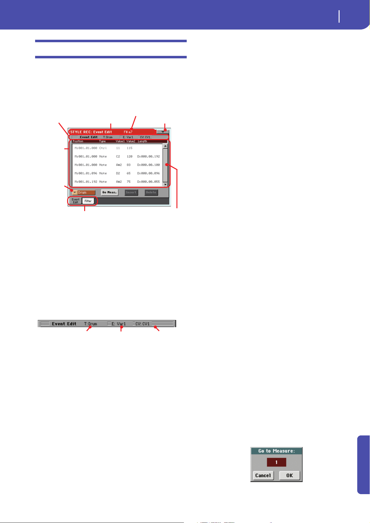
Event Edit: Event Edit
Page header Page menu icon
Track pop-
up menu
Tab s
Event list
Page s ub-header
Scrollbar
Chord
Selected track Selected Style Ele-
ment
Selected Chord Variation
The Event Edit is the page where you can edit each single MIDI
event of the selected Chord Variation. You can, for example,
replace a note with a different one, or change its playing strength
(i.e., velocity value). See “Event Edit procedure” on page 18 for
more information on the event editing procedure.
Page header
See “Page header” on page 6.
Page menu icon
Touch this icon to open the page menu. See “Page menu” on
page 31.
Page sub-header
This area shows some performing info on the Song.
17
Position
Position of the event, expressed in the form ‘aaa.bb.ccc’:
• ‘aaa’ is the measure
•‘bb’ is the beat
• ‘ccc’ is the tick (each quarter beat = 384 ticks)
You can edit this parameter to move the event to a different position. You can edit a position in either of the following ways:
(a) select the parameter, and use the VALUE controls to change
the value, or
(b) select the parameter, then touch it again; the numeric key-
pad will appear. Enter the new position by dialing in the
three parts of the number, separated by a dot. Zeroes at the
beginning can be omitted, as well as the least important
parts of the number. For example, to enter position
002.02.193, dial “2.2.193”; to enter position 002.04.000 dial
“2.4”; to enter position 002.01.000, simply dial “2”.
Type, Value 1, Value 2
Type and values of the event shown in the display. Depending on
the selected event, the value may change. This parameter also
shows the (greyed-out, so non editable) “CC#11” (Expression)
event at the beginning of the pattern, and the “End Of Loop”
marking, when the end of a track is reached.
To change the event type, select the Type parameter, then use the
VALUE controls to select a different event type. A set of default
values will be automatically assigned to the event.
To select and edit the event’s value, select the corresponding
parameter, and use VALUE controls.
Length
Length of the selected Note event. The value format is the same
as the Position value. This is only available for Note events.
Note: If you change a length of “000.00.000” to a different value,
you can’t go back to the original value. This rather uncommon
zero-length value may be found in some drum or percussion
tracks.
Selected track
Name of the track in edit. Use the Track pop-up menu to select
one of the Style tracks.
SE/CV (Style Element/Chord Variation)
Selected Style Element and Chord Variation. This parameter
cannot be edited. To select a different Style Element and Chord
Variation, press EXIT to go back to the main page of the Style
Record mode (see “Main page - Record 1” on page 6).
Event list
Use the Event list to see all events contained in the selected track
in the selected Style Element.
Use the scrollbar to browse through the events. You can also
scroll by using the SHIFT + DIAL combination.
Touch the event to be selected. Selected events are highlighted
and can be heard.
Scrollbar
Use the scrollbar to browse the event through the list. (As an
alternative, use Shift + Dial).
Other elements
Track pop-u p menu
Use this pop-up menu to select the track to edit, inside the current Chord Variation.
Drum…Acc5 Style track.
Go Meas.
While the Style is not running, touch this button to open the Go
to Measure dialog box:
Advanced
Page 20
18
Style Record mode
Event Edit: Event Edit
When in this dialog box, select a target measure, and touch OK.
The first event available in the target measure will be selected.
Insert
Touch the Insert button in the display to insert a new event at the
current shown Position. The default values are Type = Note,
Pitch = C4, Velocity = 100, Length = 192.
Delete
Touch the Delete button in the display to delete the event
selected in the display.
Event Edit procedure
Here is the general procedure to follow for the event editing.
1. Select the Style to edit, and press the RECORD button.
Select the “Current Style” option to enter recording. The
main page of the Style Record mode will appear.
2. Select the “Element (Style Element)” and “Chord Var
(Chord Variation)” parameters.
Note: For more information on the Style Elements and Chord
Variations, and the Style structure in general, see “The Style
structure” on page 3.
3. Press MENU, and select the Event Edit section. The Event
Edit page appears (see “Event Edit: Event Edit” on page 17
for more information).
4. Press START/STOP to listen to the selected Chord Varia-
tion. Press START/STOP to stop it. Chord Scanning does
not work, so you will listen the pattern at the original Key/
Chord.
5. Touch the Filter tab to select the Filter page, and uncheck
the filters for the event types you wish to see in the display
(see “Event Edit: Filter” on page 19 for more information).
6. Touch the Event Edit tab to go back to the Event Edit page.
7. Use the Track pop-up menu to select the track to edit (see
“Track pop-up menu” on page 17).
8. The list of events contained in the selected track (inside the
Chord Variation selected on step 2) will appear in the display. Some events on the beginning of the Chord Variations, as well as the “EndOfTrk” event (marking its ending
point) cannot be edited, therefore appearing in grey.
9. Scroll though the various events by using the scrollbar.
10. Select an event to be edited by touching it in the display.
This is usually a note, that you can edit.
For more information on the event types and their values, see “Event Edit: Event Edit” on page 17.
11. Edit the event.
• Select the “M” parameter. Use VALUE controls to change
the event’s position.
• Select the Type parameter. You may use VALUE controls
to change the event type, as well as its Value 1 and Value 2.
• If a Note event is selected, select the Length parameter,
and use VALUE controls to change the event’s length.
12. You may use the Go Meas. command to go to a different
measure (see “Go Meas.” on page 17)
13. As described in step 4, you may press START/STOP to lis-
ten how the pattern sounds after your changes. Press
START/STOP again to stop the pattern running.
14. Touch the Insert button in the display to insert an event at
the Position shown in the display (a Note event with default
values will be inserted). Touch the Delete button in the display to delete the selected event.
15. When editing is complete, you may select a different track
to edit (go to step 7).
16. When finished editing the selected Chord Variation, press
EXIT to go back to the main page of the Style Record
mode, then go to step 2 to select and edit a different Chord
Va ri a t io n .
17. When finished editing the whole Style, select the “Write
Style” command from the page menu to open the Write
Style dialog box (see “Write Style dialog box” on page 31),
or select the “Exit from Record” command to cancel all
changes.
• Touch the (Text Edit) button to enter the Text Edit
dialog box. Enter a name and confirm by selecting OK.
• Select a target memory location where to save the Style.
The name of the Style already existing at the selected location is shown after the Style Bank-Location number.
Wa rn i n g : If you select an existing Style and confirm writing,
the older Style is deleted and replaced by the new one. Save
the Styles you don’t want to lose to a storage device, before
overwriting them.
18. Touch OK to save the Style to the internal memory, or Can-
cel to delete any changes made in Style Record mode.
When the “Are you sure?” message appears, touch OK to
confirm, or Cancel to go back to the “Write Style” dialog
box.
Page 21
19
Style Record mode
Event Edit: Filter
No quantiza-
tion
1/8
1/4
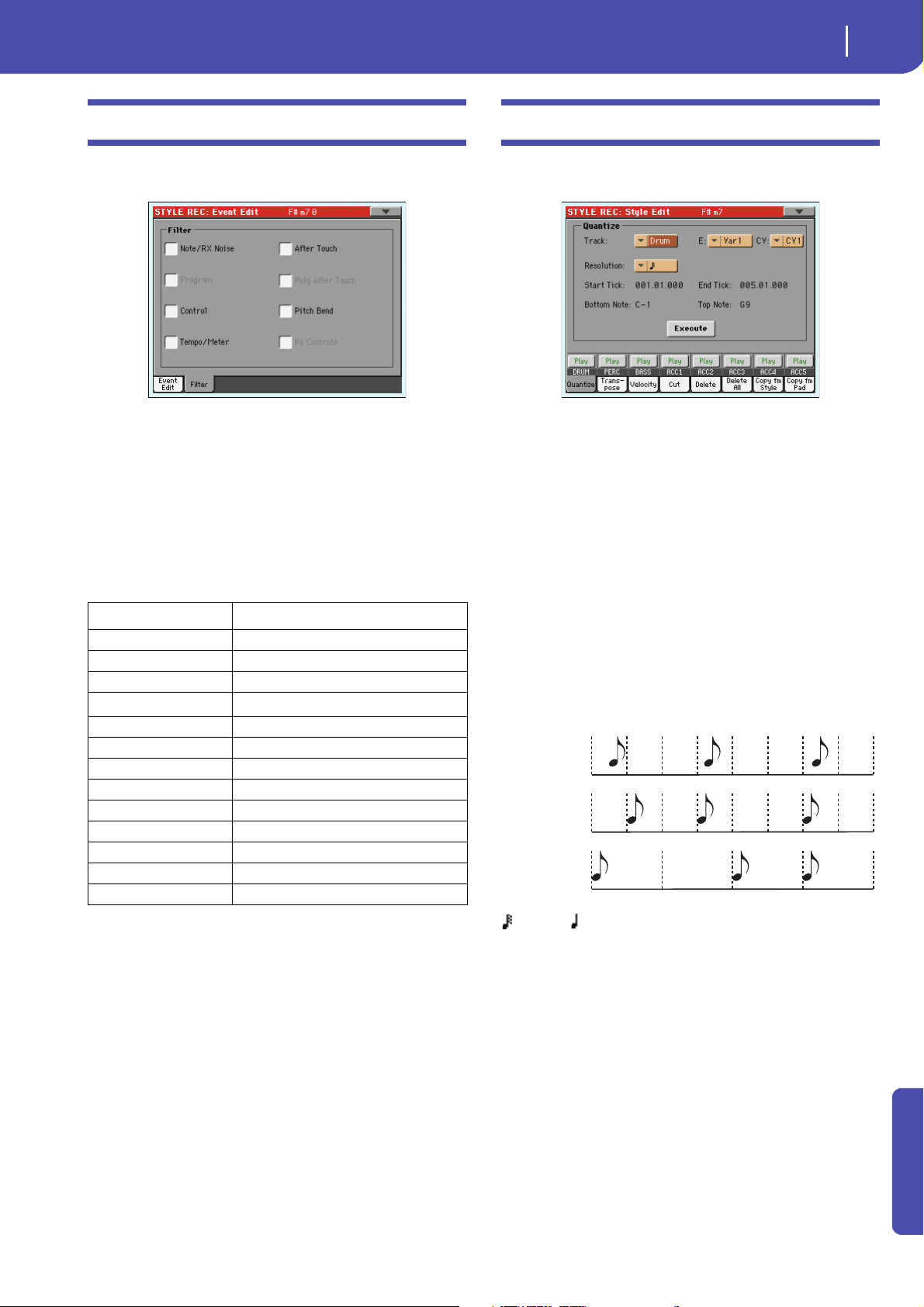
Event Edit: Filter
This page is where you can select the event types to be shown in
the Event Edit page.
Turn On the filter for all event types you do not wish to see in
the Event Edit page.
Note: Some of the events are “ghosted”, and non editable, since the
corresponding events are not editable in a Style.
Note/RX Noise
Notes and RX Noises.
Control Control Change events. Only the following Con-
trol Change numbers are allowed with Styles.
Control function CC# (Control Change Number)
Modulation 1 1
Modulation 2 2
Pan 10
Expression
CC#12 12
CC#13 13
Ribbon 16
Damper 64
Filter Resonance 71
Low Pass Filter Cutoff 74
CC#80 80
CC#81 81
CC#82 82
(a). Expression events cannot be inserted at the starting Position (001.01.000). An
Expression value is already among the default “header” parameters of the Style Element.
(a)
Tempo/Meter Tempo and Meter (time signature) changes (Mas-
ter Track only).
Pitch Bend Pitch Bend events.
11
Style Edit: Quantize
The quantize function may be used to correct any timing mistake after recording, or to give the pattern a “groovy” feeling.
After setting the various parameters, touch Execute.
Tra ck
Use this parameter to select a track.
All All tracks selected.
Drum…Acc5 Selected track.
E / CV (Style Element/Chord Variation)
Use these parameters to select the Style Element and Chord
Variation for e d i t i n g .
Resolution
This parameter sets the quantization after recording. For example, when you select 1/8, all notes are moved to the nearest 1/8
division. When you select 1/4, all notes are moved to the nearest
1/4 division.
(1/32)… (1/4)
Grid resolution, in musical values. A “b…f ” character added after the value means swing-quantization. A “3” means triplet.
Start / End Tick
Use these parameters to set the starting and ending points of the
range to quantize.
If a Chord Variation is four measures long, and you want to
select it all, the Start will be positioned at 1.01.000, and the End
at 5.01.000.
Bottom / Top Note
Use these parameters to set the bottom and top of the keyboard
range to quantize. If you select the same note as the Bottom and
Advanced
Page 22
20
Style Record mode
Style Edit: Transpose
Top parameters, you can select a single percussive instrument in
a Drum or Percussion track.
Note: These parameters are available only when a Drum or Percussion track is selected.
Execute
Touch this button to execute the operation set in this page.
Track status icon
Status of tracks. Touch this icon to change the status.
Play status. The track can be heard.
Mute status. The track cannot be heard.
Track names
Under the buttons, a label for each track is shown.
Style Edit: Transpose
In this page you can transpose the selected track(s).
Note: After transposing, please don’t forget to readjust the “Key/
Chord” parameter in the main page of the Style Record mode (see
page 7).
If a Chord Variation is four measures long, and you want to
select it all, the Start will be positioned at 1.01.000, and the End
at 5.01.000.
Bottom / Top Note
Use these parameters to set the bottom and top of the keyboard
range to be transposed. If you select the same note as the Bottom
and Top parameters, you can select a single percussive instrument in a Drum or Percussion track. Since in a Drum Kit each
instrument is assigned to a different note of the scale, transposing a percussive instrument means assigning the part to a different instrument.
Execute
Touch this button to execute the operation set in this page.
Track status icon
Status of tracks. Touch this icon to change the status.
Play status. The track can be heard.
Mute status. The track cannot be heard.
Track names
Under the buttons, a label for each track is shown.
After setting the various parameters, touch Execute.
E / CV (Style Element/Chord Variation)
Use these parameters to select the Style Element and Chord
Variation for editing.
Tra ck
Use this parameter to select a track.
All All tracks selected, apart for tracks set in Drum
mode (like the Drum and Percussion tracks). The
whole selected Chord Variation will be transposed.
Drum…Acc5 Single selected track.
Value
Transpose value (±127 semitones).
Start / End Tick
Use these parameters to set the starting and ending points of the
range to be transposed.
Style Edit: Velocity
In this page you can change the velocity (dynamics) value of
notes in the selected track. An Advanced mode is available,
allowing you to select a velocity curve for the selected range.
This is useful to create fade-ins or fade-outs.
After setting the various parameters, touch Execute.
Note: When an RX Sound is assigned to the track being edited, the
resulting sound may change, since this kind of Sounds is made of
several different layers triggered by different velocity values.
Also, a fade-out may result in the level “jumping” up next to the
zero, since a higher-level layer may be selected by low velocity values.
Tra ck
Use this parameter to select a track.
All All tracks selected. The velocity for all notes of
the whole selected Chord Variation will be
changed.
Drum…Acc5 Selected track.
Page 23
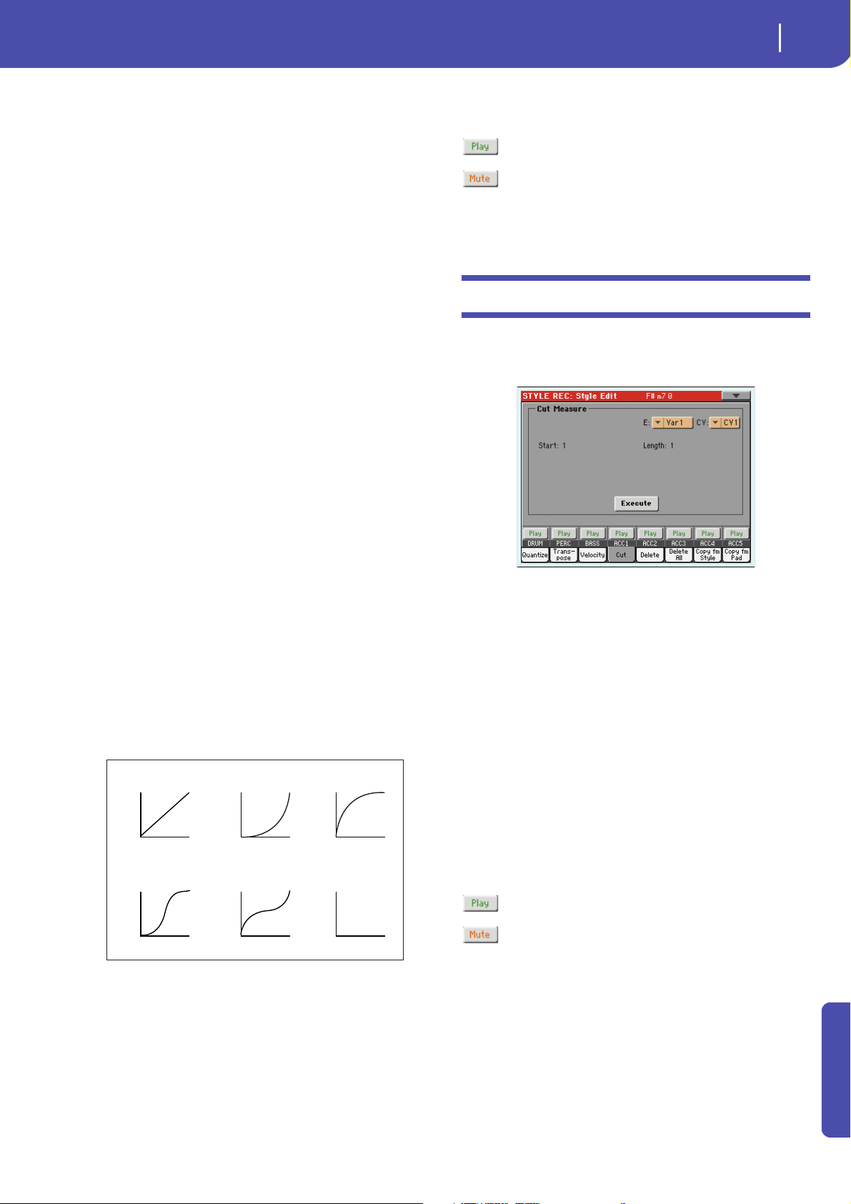
21
Style Record mode
Style Edit: Cut
Start
Value
Curve 1
Velocity
Start Value = 0%, End Value = 100%
127
1
End
Value
Start
Value
Curve 2
Velocity
127
1
End
Value
Start
Value
Curve 3
Velocity
127
1
End
Value
Start
Value
Curve 4
Velocity
127
1
End
Value
Start
Value
Curve 5
Velocity
127
1
End
Value
Start
Value
Curve 6
Velocity
RANDOM
127
1
End
Value
E / CV (Style Element/Chord Variation)
Use these parameters to select the Style Element and Chord
Variation for e d i t i n g .
Value
Velocity change value (±127).
Start / End Tick
Use these parameters to set the starting and ending points of the
range to be modified.
If a Chord Variation is four measures long, and you want to
select it all, the Start will be positioned at 1.01.000, and the End
at 5.01.000.
Bottom / Top Note
Use these parameters to set the bottom and top of the keyboard
range to be modified. If you select the same note as the Bottom
and Top parameters, you can select a single percussive instrument in a Drum or Percussion track.
Advanced
When this checkbox is checked, the “Intensity”, “Curve”, “Start
Velocity Value” and “End Vel o ci t y Va lue” p a r a m e t e r s can b e
edited.
Track status icon
Status of tracks. Touch this icon to change the status.
Play status. The track can be heard.
Mute status. The track cannot be heard.
Track names
Under the buttons, a label for each track is shown.
Style Edit: Cut
This function lets you quickly delete a selected measure (or a
series of measures) from the selected Chord Variation. All following events are moved back, to replace the cut measure(s).
Intensity
(Only available in Advanced mode). Use this parameter to specify
the degree to which the velocity data will be adjusted toward the
curve you specify in “Curve”.
0…100% Intensity value. With a setting of 0 [%], the veloc-
ity will not change. With a setting of 100 [%], the
velocity will be changed the most.
Curve
(Only available in Advanced mode). Use this parameter to select
one of the six curves, and to specify how the velocity will change
over time.
After setting the various parameters, touch Execute.
E / CV (Style Element/Chord Variation)
Use these parameters to select the Style Element and Chord
Variation for e d i t i n g .
Start
First measure to be cut.
Length
Number of measures to be cut.
Execute
Touch this button to execute the operation set in this page.
Track status icon
Status of tracks. Touch this icon to change the status.
Play status. The track can be heard.
Mute status. The track cannot be heard.
Start / End Vel. Value
(Only available in Advanced mode). Velocity change at the starting and ending ticks of the selected range.
0…100 Velocity change in percentage.
Execute
Touch this button to execute the operation set in this page.
Track names
Under the buttons, a label for each track is shown.
Advanced
Page 24
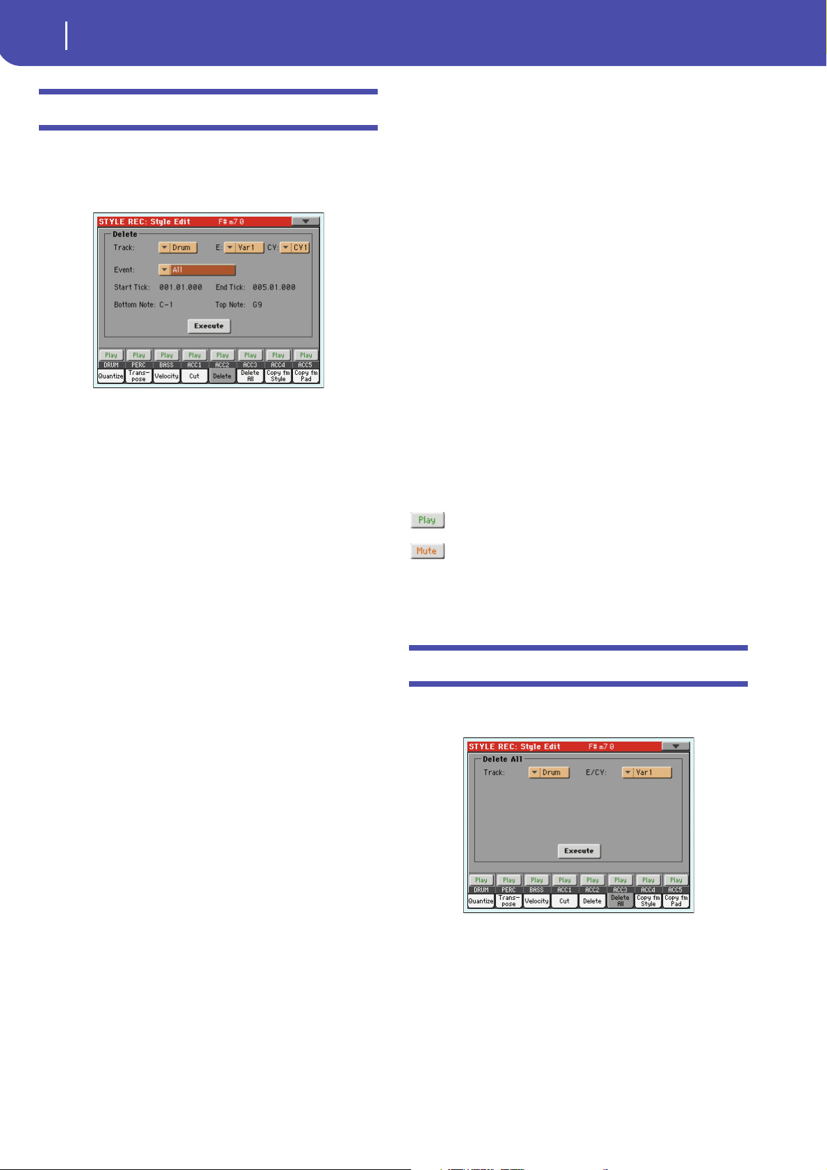
22
Style Record mode
Style Edit: Delete
Style Edit: Delete
Note: Some CC data are automatically removed
during recording. See the table on page 5 for more
information on the allowed data.
This page is where you can delete MIDI events out of the Style.
This function does not remove measures from the pattern. To
remove whole measure, use the Cut function (see “Style Edit:
Cut” on page 21)
After setting the various parameters, touch Execute.
E / CV (Style Element/Chord Variation)
Use these parameters to select the Style Element and Chord
Variation for editing.
Tra ck
Use this parameter to select a track.
All All tracks selected. After deletion, the selected
Chord Variation will remain empty.
Drum…Acc5 Selected track.
Event
Type of MIDI event to delete.
All All events. The measures are not removed from
the Chord Variation.
Note All notes in the selected range.
Dup.Note All duplicate notes. When two notes with the
same pitch are encountered on the same tick, the
one with the lowest velocity is deleted.
After Touch After Touch events.
Note: This kind of data is automatically removed
during recording.
Pitch Bend Pitch Bend events.
Prog.Change Program Change events, excluding the bundled
Control Change #00 (Bank Select MSB) and #32
(Bank Select LSB).
Note: This kind of data is automatically removed
during recording.
Ctl.Change All Control Change events, for example Bank
Select, Modulation, Damper, Soft Pedal…
CC00/32…CC127
Single Control Change events. Double Control
Change numbers (like 00/32) are MSB/LSB bundles.
Start / End Tick
Use these parameters to set the starting and ending points of the
range to delete.
If a Chord Variation is four measures long, and you want to
select it all, the Start will be positioned at 1.01.000, and the End
at 5.01.000.
Bottom / Top Note
Use these parameters to set the bottom and top of the keyboard
range to delete. If you select the same note as the Bottom and
Top parameters, you can select a single percussive instrument in
a Drum or Percussion track.
Note: These parameters are available only when the All or Note
option is selected.
Execute
Touch this button to execute the operation set in this page.
Track status icon
Status of tracks. Touch this icon to change the status.
Play status. The track can be heard.
Mute status. The track cannot be heard.
Track names
Under the buttons, a label for each track is shown.
Style Edit: Delete All
This function lets you quickly delete a selected Style Element or
Chord Variation, or the whole Style.
After setting the various parameters, touch Execute.
Tra ck
All All tracks of the selected Style, Style Element or
Chord Variation.
Drum-Acc5 Single track of the selected Style, Style Element or
Chord Variation.
Page 25
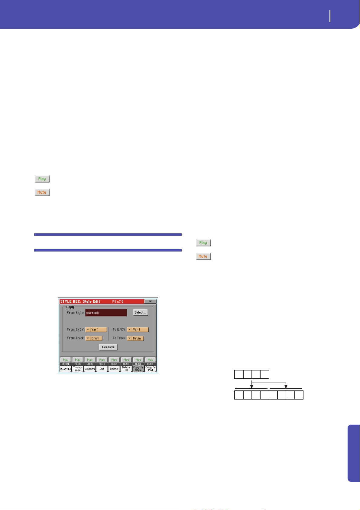
23
Style Record mode
Style Edit: Copy from Style
1 2 3 4
1 2 3 4 1 2 3 4
E / CV (Style Element/Chord Variation)
Use these parameters to select the Style Element and Chord
Variation for e d i t i n g .
All All Style Elements, i.e. the whole Style. When E/
Track=All and CV=All, the whole Style is deleted,
and all parameters are set to the default status.
Va r 1… C o u nt I n
Single Style Element.
V1-CV1…CI-CV2
Single Chord Variation.
Execute
Touch this button to execute the operation set in this page.
Track st atus icon
Status of tracks. Touch this icon to change the status.
Play status. The track can be heard.
Mute status. The track cannot be heard.
Track na mes
Under the buttons, a label for each track is shown.
From… To E/CV (Style Element/Chord Variation)
Use these parameters to select the source and target Style Elements or Chord Variations.
Note: You can’t copy from a Variation to a different Style Element
(or vice-versa), because of their different structure.
All All Style Elements, i.e. the whole Style. You can’t
change the target, that is automatically set to All.
Var1…End2 Single Style Element.
V1-CV1…E2-CV2
Single Chord Variation.
From… To Track
Use this parameter to select the source and target track to copy.
You can double a track, to strengthen a pattern.
All All tracks of the selected Style, Style Element or
Chord Variation.
Drum-Acc5 Single track of the selected Style, Style Element or
Chord Variation.
Execute
Touch this button to execute the operation set in this page.
Track status icon
Status of tracks. Touch this icon to change the status.
Style Edit: Copy from Style
Here you can copy a track, Chord Variation or Style Element
inside the same Style, or from a different one. Furthermore, you
can copy a whole Style.
Wa r n in g : The Copy operation deletes all data at the target location (overwrite).
After setting the various parameters, touch Execute.
Note: If you copy too many events on the same “tick”, the “Too
many events!” message appears, and the copy operation is aborted.
Note: When you copy over an existing Chord Variation, Program
Change data is not copied, to leave the original Sounds unchanged
for that Chord Variation.
From Style
Choose this option to select the source Style to copy the track,
Chord Variation or Style Element from. Touch the Select button
to open the Style Select window and select the source Style.
Play status. The track can be heard.
Mute status. The track cannot be heard.
Track names
Under the buttons, a label for each track is shown.
Copying to a Chord Variation of a different length
You can copy a Chord Variation to a different one of a different
length. Just keep in mind the following:
• If the source length is a divider of the target length, the
source Chord Variation will be multiplied to fit the target
Chord Variation. For example, if the source is 4-measures
long, and the target 8-measures, the source will be copied
two times.
• If the source length is not a divider of the target length, the
source Chord Variation will be copied for as many measures as can fit the target Chord Variation. For example, if
the source is 6-measures long, and the target 8-measures,
Advanced
Page 26
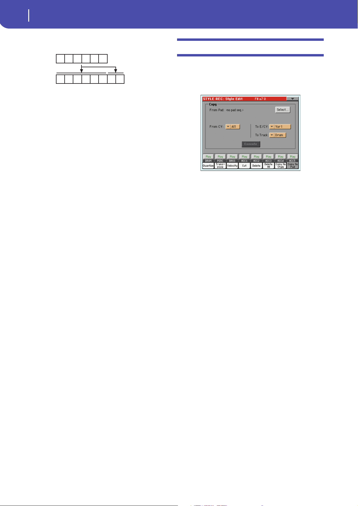
24
Style Record mode
Style Edit: Copy from Pad
1 2 3 4
1 2 3 4 5 6 1 2
5 6
the source will be copied once, then the first 2 measures
will be copied to fit the remaining 2 measures.
Note: Avoid copying to a Chord Variation with a different meter
(time signature), for example a 4/4 Chord Variation onto a 3/4
one.
Style Edit: Copy from Pad
Here you can copy a Chord Variation from a Pad. Furthermore,
you can copy a whole Pad.
Wa r ni n g : The Copy operation deletes all data at the target location (overwrite).
After setting the various parameters, touch Execute.
Note: If you copy too many events on the same “tick”, the “Too
many events!” message appears, and the copy operation is aborted.
Note: When you copy over an existing Chord Variation, Program
Change data is not copied, to leave the original Sounds unchanged
for that Chord Variation.
From Pad
Choose this option to select the source Pad to copy the Chord
Variation from . To u c h t h e Select button to open the Pad Select
window and select the source Pad.
From CV (Chord Variation)
Use this parameter to select the source Chord Variation.
All All Chord Variations, i.e. the whole Pad. You can’t
change the target, that is automatically set to All.
CV1…CV6 Single Chord Variation.
To CV (Chord Variation)
Use this parameter to select a target Chord Variation inside the
current Style.
CV1…CV6 Target Chord Variation. Automatically set to All
if the “From CV” parameter is also set to All.
To Trac k
Use this parameter to select the target track to copy.
All All tracks of the selected Style, Style Element or
Chord Variation.
Drum-Acc5 Single track of the selected Style, Style Element or
Chord Variation.
Execute
Touch this button to execute the operation set in this page.
Page 27
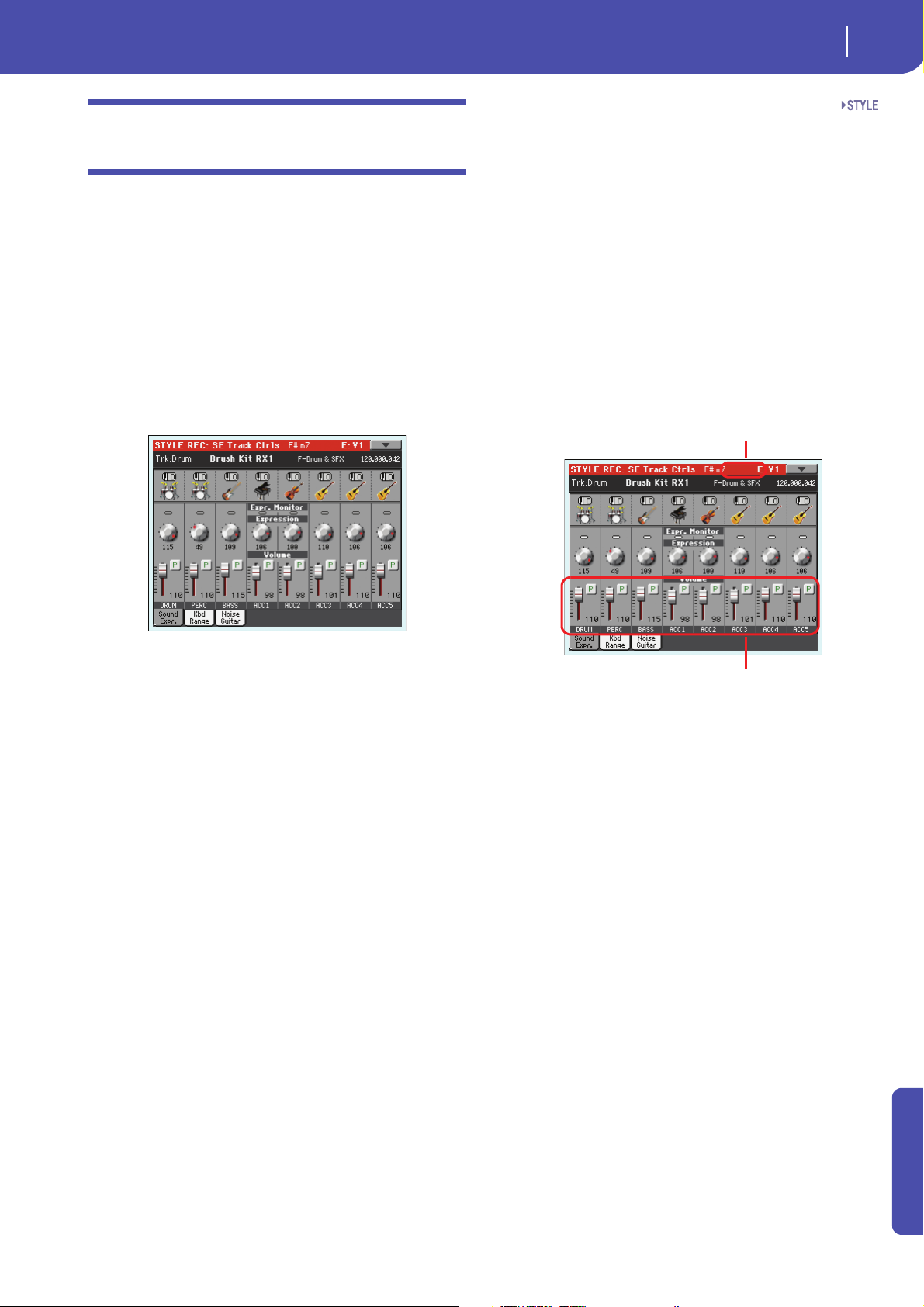
Style Record mode
Style Element Track Controls: Sound/Expression
Style Element Track Controls: Sound/
Selected Style E lement
Expression level
Expression
In this page you can assign a different Sound to each track of the
selected Style Element. Each Style Element can have different
Sound; after saving the new Style, please don’t forget to check the
“Original Style Sounds” parameter in the Style Play mode (see
page 114), to let the Style select the Sound bypassing the Style
Performance settings.
In this page you can also check and modify the Expression
(CC#11) value for each of the Style Element tracks. This lets you
reduce the relative level of a track in a single Style Element, without reducing the overall Volume of the Style. This is a very useful
control, when you have different Sounds assigned to the same
track in different Style Elements, and the internal level of these
Sounds must be different.
25
Expression
Use these knobs to set the Expression (CC#11) value for the corresponding track. This value can be seen at the beginning of the
Event Edit list (see “Event Edit: Event Edit” on page 17).
Different Expression values can be defined for each Style Element. This way, you can set a different volume in each Style Element, relative to the general Volume value set in the Style
Header.
Expression leveling
You can quickly and easily adjust the Expression level of all
tracks in a Style Element (Variation, Intro…). This allows for a
more precise control over the volume level of all Style Element.
1. While in this page, select one of the Style Elements by
pressing its button in the control panel.
When in this page, press the corresponding button on the
control panel to select a Style Element (VARIATION1 …
ENDING3).
To copy the settings of this page to another Style Element, use
the “Copy Sound” and “Copy Expression” commands from the
page menu (see “Copy Sounds dialog box” and “Copy Expression dialog box” starting from page 32).
Selected Track Info area
See “Selected track info area” on page 7 for detailed information.
Sounds area
See “Sounds area” on page 9 for detailed information.
Expression area
Expression Monitor
You can use these indicators to check if CC#11 (Expression)
messages are contained in a track. Expression messages contained in a track can vary the volume of the track. It is very difficult to catch them out – unless you carefully read all the events
in the Event Edit page.
This monitor should help you keeping track of them, and let you
access Event Edit only on the tracks containing the messages.
Press the START/STOP button to start playback, and look at the
indicators. When one of them lights up, you can enter Event Edit
on the corresponding track, and edit or remove the Expression
messages.
2. Keep the SHIFT button pressed, and move any Assignable
Slider to proportionally change the Expression value of all
Style Variation tracks.
3. Release the SHIFT button.
4. Repeat the above operation with all the desired Style Ele-
ments.
Note: A track’s volume may be changed by an Expression event
contained in a track. To check if any of these events exist in a track,
let the Style Element play and look at the Expression Monitor in
this same page. If one or more Expression events are found, go to
the Event Edit page and delete it (or them)
Volume area
Use these controls to set the volume and status of each track. See
page 9 for more information.
The Volume value is the same for the whole Style. Use the
Expression controls to adjust the relative balance between tracks
in each Style Element.
Advanced
Page 28
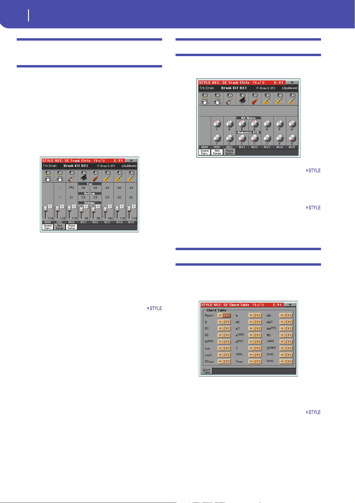
26
Style Record mode
Style Element Track Controls: Keyboard Range
Style Element Track Controls: Keyboard
Range
The Keyboard Range automatically transposes any pattern note
that would otherwise play too high or too low in pitch, compared to the original acoustic instrument, when transposed by
the arranger. This will result in a more natural sound for each
accompaniment instrument.
For example, the lower limit for a guitar is E2. If you play a chord
under the E2, the transposed pattern could exceed this limit, and
sound unnatural. A Bottom limit set to E2 for the guitar track
will solve the problem.
Different Keyboard Range values can be set for each Style Element.
Note: The Keyboard Range is ignored while recording. The selected
track can play on the full range of the keyboard.
When in this page, press the corresponding button on the
control panel to select a Style Element (VARIATION1 …
ENDING3).
To copy the settings of this page to another Style Element, use
the “Copy Keyboard Range” command from the page menu (see
“Copy Key Range dialog box” on page 33).
Style Element Track Controls: Noise/Guitar
The Noise/Guitar page is where you can set the RX Noise level
and the ‘human feel’ of Guitar tracks.
RX Noise
Use these controls to adjust the volume of RX Noises in the corresponding tracks. This control applies to all types of tracks
(provided the Sound includes RX Noises).
Humanize GTR
Use these controls to apply a random value to the position,
velocity and length of notes of Guitar tracks (see “Track Type”
on page 27). This control has no effect on other types of track.
Style Element Chord Table: Chord Table
This is the page where you can assign a Chord Variation to each
of the most important recognized chord. When a chord is recognized, the assigned Chord Variation will be automatically
selected by the arranger to play the accompaniment.
To p/ B ot t om
Use these parameters to set the bottom and top of the keyboard
range for the corresponding track of the current Style Element.
Volume area
Use these controls to set the volume and status of each track. See
page 9 for more information.
When in this page, press the corresponding button on the
control panel to select a Style Element (VARIATION1 …
ENDING3).
Chord / Chord Variation
Use these parameters to assign a Chord Variation to each of the
most important chords.
Page 29
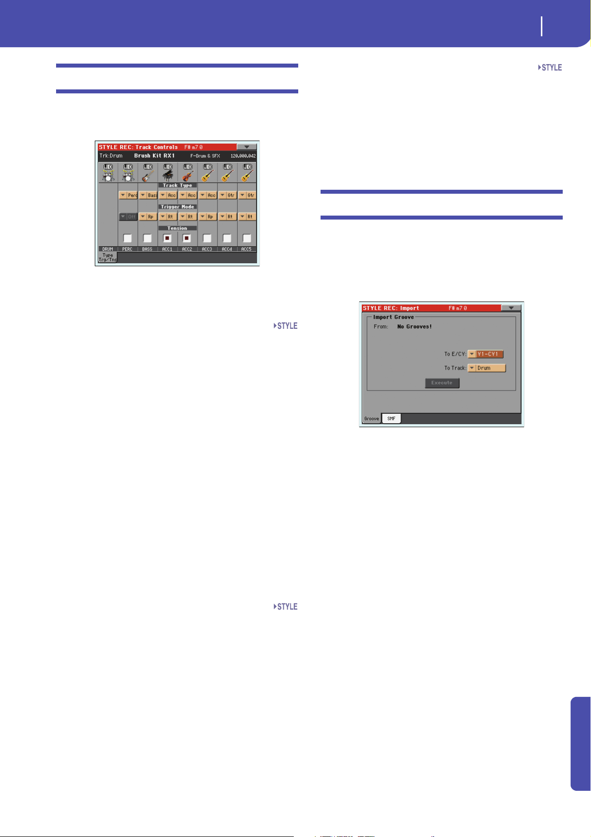
Style Record mode
Style Track Controls: Type/Trigger/Tension
Style Track Controls: Type/Trigger/Tension
In this page you can set the Mode, Retrigger mode for the Style
tracks, and activate/deactivate the Tension for the Accompaniment tracks.
When in this page, press the corresponding button on the
control panel to select a Style Element (VARIATION1 …
ENDING3).
27
Te ns i on
Tension adds notes (a 9th, 11th and/or 13th) that have actually
been played to the accompaniment, even if they haven't been
written in the Style pattern. This parameter specifies whether or
not the Tension included in the recognized chord will be added
to the Acc-type tracks.
On The Tension will be added.
Off No Tension will be added.
Import: Import Groove
The Import Groove function allows the loading of MIDI
Grooves (“.GRV” files) generated by the Slice function (in the
“Time Slice” page of the Sampling modem see page 85). By
importing these data to a track, and assigning the Sound based
on the sliced samples to the same track, you can play the original
audio groove, and freely change its tempo.
Track Type
Use this parameter to set the type of the corresponding track.
Drum Drum track. This type of track is not transposed
by the arranger, and is used for Drum Kits made
of Drum sounds. It can be affected by the Drum
Mapping of the Style Play mode (see “Drum
Mapping (Var.1…Var.4)” on page 134).
Perc Percussion track. This type of track cannot be
transposed, and is used for Drum Kit made of
Percussion sounds. It is NOT affected by the
Drum Mapping.
Bass Bass track. This type of track always plays the
root when changing chord.
Acc Accompaniment track. This type of track can be
used freely, for melodic or harmonic accompaniment patterns.
Gtr Guitar track. This type of track uses Guitar Mode
to create guitar strumming (see “Main page Guitar Mode” on page 10). When this type is
selected, the “Tension” parameter can no longer
be edited.
Trigg er Mode
This setting lets you define how Bass and Acc-type tracks are
retriggered when the chord is changed.
Off Each time you play a new chord, current notes
will be stopped. The track will remain silent until
a new note will be encountered in the pattern.
Rt (Retrigger) The sound will be stopped, and new
notes matching the recognized chord will be
played back.
Rp (Repitch) New notes matching the recognized
chord will be played back, by repitching notes
already playing. There will be no break in the
sound. This is very useful on Guitar and Bass
tracks.
Note: After importing a groove generated by a melody line (not by
a percussive groove), the imported groove and samples will not be
transposed together with the other Style tracks. Audio data cannot
be transposed by the arranger.
Note: Please execute the Import Groove operation before turning
the instrument off. All “.GRV” files generated by a Time Slice operation are deleted when turning the instrument off.
From
Use this parameter to select one of the MIDI Groove patterns
(“.GRV” files) generated when saving data after a Time Slice
operation.
To E/CV (Style Element/Chord Variation)
Use this parameter to select the target Style Element and Chord
Va r ia t i on .
To Trac k
Use this parameter to select the target track inside the selected
Chord Variation. The Percussion track is usually suggested,
since the Drum track is still suitable for standard Drum Kit
sounds (count-in, break etc.). After importing the MIDI Groove
pattern, assign the Sound, to which the sliced samples are
assigned, to the track playing the MIDI Groove pattern.
Advanced
Page 30
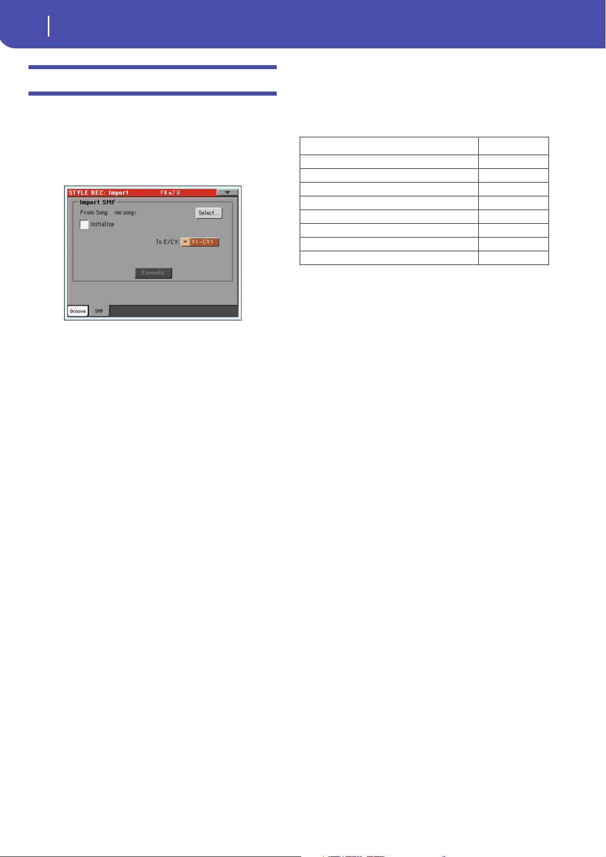
28
Style Record mode
Import: Import SMF
Import: Import SMF
The Import SMF function allows you to import MIDI data from
a Standard MIDI File (SMF) created on your preferred external
sequencer, and transform them in a Chord Variation.
Note: You cannot use this function to import data from any
generic Song. The Standard MIDI File to be imported must be programmed as if it was one of Pa3X’s Chord Variations.
When importing an SMF, parameters like CV Length, Meter,
Tempo Changes, Program Changes and Expression are recognized. These parameters will be imported as the header of the
Style Element containing the Chord Variation, provided the
“Initialize” parameter is checked, or the Style Element is empty.
Hint: It is a good idea to check the “Initialize” parameter when
importing the first Chord Variation of a Style Element, and
uncheck it when importing the following Chord Variations.
• Sounds assigned to each track can be imported, provided the
Program Change, Bank Select MSB and LSB events are on the
first ‘tick’ of the SMF. These data are loaded in the Style Element’s header, and not as Sounds assigned to the Style Performance.
Note: Sounds in the Style Element header can be overridden by
Sounds assigned to the Style Performance, by checking the “Original Style Sound” parameter in the main page of the Style Play
mode (Style Track view).
• If the above data was not found on the first ‘tick’ of the
imported SMF, Sounds must be manually assigned to each track.
You can do this in the “Record 1” or “Record 2”, or the “Sound/
Expression” page of the Style Record mode,.
• Key/Chord, Chord Table, Expression, and any other Style Variation parameter, must be manually programmed in the relevant
Style Record pages.
• The starting Tempo, and each track’s Volume, must be programmed as Style Performance data, and then saved in the Style
Performance.
• Meter (time signature) Change is not allowed, therefore not
recognized.
• The Chord Variation length is the same as the imported SMF.
You can change length by changing the value of the CV Length
parameter, on the main page of the Style Record mode.
Hint: If a note extends beyond the last measure of the Chord Variation, an additional measure is appended (for example, if a note
extends after the end of the fourth measure in a 4-measure pattern, a 5-measure Chord Variation will be generated). If so, change
the CV Length value to reset the Chord Variation length. The
exceeding note will be cut, to fit the new pattern length.
When programming a Chord Variation on an external
sequencer, please assign each Style track to the correct MIDI
channel, according to the following table.
Style Track MIDI Channel
Bass 09
Drum 10
Percu ssion 11
Accompaniment 1 12
Accompaniment 2 13
Accompaniment 3 14
Accompaniment 4 15
Accompaniment 5 16
Note: Only SMF in format 0 can be loaded.
From Song
This is the name of the Standard MIDI File to be loaded. Touch
the Select button to open the file selector, and select an “.SMF”
file.
Select
Touch this button to open the file selector and load the SMF.
Initialize
Check this parameter if you want all settings of the target Style
Element (i.e., Key/Chord, Chord Table, Sounds…) are reset
when loading the SMF.
Hint: It is a good idea to check the “Initialize” parameter when
importing the first Chord Variation of a Style Element, and
uncheck it when importing the following Chord Variations.
To E/ CV
Use this parameter to select a target Chord Variation.
Execute
After setting all parameters in this page, touch this button to
import the Standard MIDI File into the target Chord Variation.
Page 31

29
Style Record mode
Import: Import SMF
Importing an SMF separated by Markers into a Style
As an alternative to importing single Chord Variations, you can
import a whole Style as an SMF separated by Markers, i.e., a sin-
gle SMF containing all the Chord Variations (Variation 1, Variation 2, etc.) each one separated by a Marker (the same events
used in Song Play mode).
1. While in this page, touch the Select button, and choose the
Standard Midi File to be imported.
2. Keep the SHIFT button pressed.
3. Without releasing the SHIFT button, touch the Execute
button in the display.
4. Release the SHIFT button.
When creating a new Style, we suggest to check the “Initialize”
checkbox. Do not check it if the SMF you are loading was previously exported from a Style to be edited; in this case, it is very
important to keep all the previous settings.
Style Tracks and MIDI Channels must be lined as in the previous
table, as per Korg’s standard Style format definition.
Note: Tracks/MIDI Channels other than the above mentioned are
ignored during the import procedure.
For a list of MIDI events supported during the import operations, please see “List of recorded events” on page 5. If any, the
following events are stripped off and automatically transferred to
the Style Element header during the import procedure:
• Time signature (this event is mandatory)
• Control Change bundle #00-32 (Bank Select MSB/LSB)
• Program Change
• Control Change #11 (Expression)
Control Change 00, Control Change 32 and Program Change
messages must be placed at the very beginning of each Chord
Variation ( t i c k 0 ) .
Whenever they are not saved in the SMF, Program Change, Control Change 00, 11 and 32, can be still programmed in Style
Record mode, by using the edit features available.
Wa r n in g : Pa3X can only handle SMF format 0 (Zero). If you are
in trouble importing your file, maybe your sequencer (or DAW) is
exporting using a different format. Please refer to the software’s
user’s manual.
The naming structure for the Markers inside the SMF is
“EnCVn”, whose single components are shown in the following
table:
Component Meaning
E Style Element (‘v’ = variation, ‘i’ = intro, ‘f’ = fill,
‘e’ = ending)
n Style Element number (‘1’~’4’ for variations, ‘1’~’2’ for all
other style elements)
CV Chord Variation (‘cv’ = chord variation – no other choices
allowed)
n Chord Variation number [1~6 for Variations, 1~2 for all oth-
ers]
Wa r n in g : It is mandatory not to use capital letters in Marker
names. Some examples of valid names:
‘i1cv2’ = Intro1 – Chord Variation 2
‘v4cv3’ = Variation 4 – Chord Variation 3
Examples of non accepted names:
‘V1cv2’, ‘v1CV2’, ‘intro i1cv2’, ‘v1cv1 chorus’
The order of the Chord Variations inside the SMF is not relevant.
They can be freely placed inside the SMF.
At the end of this page you can find a screenshot of a test file created in Steinberg Cubase, just as an example of how a SMF sepa-
rated by Markers can look like. Considering analogies between
actual workstations, it will not look much different in other
applications like Logic, Digital Performer, Pro Tools or Sonar.
Advanced
Page 32

30
Style Record mode
Export SMF
Export SMF
Exporting a Style as an SMF separated by Markers
The Export SMF function allows you to export a Chord Variation as a Standard MIDI File (SMF), and edit it on your preferred
external sequencer.
To Son g
This (non editable) parameter shows the name of the Standard
MIDI File to be generated. The (automatically assigned) name
will be the same of the exported Chord Variation.
From E/CV
Use this pop-up menu to select one of the available Chord Variations from the current Style.
Execute
After selecting a Chord Variation, touch this button to export it
as a Standard MIDI File. A standard file selector will appear.
Select the target device and directory, then touch Save. After you
touch Save, a dialog box appears, letting you assign a name to the
file.
As an alternative to exporting single Chord Variations to individual Standard MIDI Files, you can export a whole Style as an
SMF separated by Markers, i.e., a single SMF containing all the
Chord Variations (Variation 1, Variation 2, etc.) each one separated by a Marker (the same events used in Song Play mode).
1. While in this page, keep the SHIFT button pressed.
2. Without releasing the SHIFT button, touch the Execute
button in the display.
3. Release the SHIFT button.
4. Assign a name to the Standard Midi File where to save the
Style in edit.
This operation creates, in the selected device, an SMF format 0
(Zero), containing all the MIDI data included in the selected
Style, with each Chord Variation starting from a different
Marker (named as per the naming convention explained in the
Import section above).
Each Chord Variation will include, at the very beginning (tick 0),
the following informations:
•Time signature
• Control Change bundle #00-32 (Bank Select MSB/LSB)
• Program Change
• Control Change #11 (Expression)
Page 33

Style Record mode
Page menu
Page menu
Touch the page menu icon to open the page menu. Touch a command to select it. Touch anywhere in the display to close the
menu without selecting a command.
Write Style
Select this command to open the Write Style dialog box, and
save the Style to the internal memory.
See “Write Style dialog box” on page 31 for more information.
Undo
Only available in Record mode. While in Record mode, cancels
the latest recorded data and restores the previous situation.
Selected a second time, it restores recorded data again (“Redo”
function).
31
Copy Chord Table
Only available while in the Style Element Chord Table page. Select
this command to open the Copy Chord Table dialog box (see
“Copy Chord Table dialog box” on page 33).
Delete Current Track
(Only available in the Main Record pages). Select this command
to delete the selected track.
Overdub Step Recording
(Only available in the Main Record pages). Select this command
to open the Overdub Step recording window (see “Overdub Step
Recording window” on page 33).
Solo Track
Select the track to be soloed, then check this item. You will hear
only the selected track, and the ‘Solo’ warning will flash on the
page header.
Uncheck this item to exit the Solo function.
Keep the SHIFT button pressed and touch one of the
tracks to solo it. Do the same on a soloed track to deactivate the
Solo function.
Exit from Record
Select this command to exit from Record without saving changes
to the Style.
Copy Key/Ch (Copy Key/Chord) button
Select this command to open the Copy Key/Chord dialog box,
and copy Key/Chord settings of the currently selected track to all
other tracks of the same Chord Variation, or to the whole Style.
See “Copy Key/Chord dialog box” on page 32 for more information.
Copy Sound
(Only available in some edit pages). While the Style Element
Track Control edit section is selected, use this command to open
the Copy Sound dialog box and copy all Sounds assigned to the
current Style Element tracks to a different Style Element.
See “Copy Sounds dialog box” on page 32 for more information.
Copy Expression
(Only available in some edit pages). While the Style Element
Track Control edit section is selected, use this command to open
the Copy Expression dialog box and copy all Expression values
assigned to the current Style Element tracks to a different Style
Element.
See “Copy Expression dialog box” on page 32 for more information.
Copy Keyboard Range
(Only available in some edit pages). While the Style Element
Track Control edit section is selected, use this command to open
the Copy Keyboard Range dialog box and copy all Keyboard
Range values for the current Style Element tracks to a different
Style Element.
See “Copy Key Range dialog box” on page 33 for more information.
Write Style dialog box
Open this window by choosing the Write Style item from the
page menu. Here you can save the recorded or edited Style to
memory, by choosing either a User or Favorite Style bank.
Parameters saved in the Style are marked with the symbol
through the user’s manual.
Name
Name of the Style to be saved. Touch the (Text Edit) button
next to the name to open the Text Edit window.
Style Bank
Target bank of Styles. Each bank corresponds to one of the
STYLE SELECT buttons. Use VALUE controls to select a different bank.
Style
Target Style location in the selected bank. Use VALUE controls
to select a different location.
Advanced
Page 34

32
Style Record mode
Copy Key/Chord dialog box
Note: A User or Favorite Style is usually prompted when writing a
Style. However, you can overwrite a Factory Style, when the “Factory Style and Pad Protect” parameter is left unchecked (see
page 236).
Select… button
Touch this button to open the Style Select window, and select a
target location.
Copy Sounds dialog box
Open this window by choosing the Copy Sounds item from the
page menu. Here you can copy all Sounds assigned to the current
Style Element tracks to a different Style Element.
From Style Element
Non editable. Currently selected Style Element.
While in the Style Select window, use the buttons on top of the
window to select either the User or the Favorite banks.
Copy Key/Chord dialog box
Open this window by choosing the Copy Key/Chord item from
the page menu. Here you can copy Key/Chord settings of the
currently selected track to all other tracks of the same Chord
Variation, or to the whole Style. This function is useful to speedup pattern programming, and to avoid having different tracks in
different keys within the same Chord Variation.
Current Chord Variation Tracks
The Key/Chord of the current track will be copied to all tracks of the current Chord Variation.
All Style Tracks
The Key/Chord of the current track will be copied to all tracks of the Style (i.e., all Chord Variations).
To Style Element
Target Style Element.
All Settings will be copied to all Style Element of the
Style in edit.
Va r1 … C ou n tI n
Single Style Element where to copy settings to.
Copy Expression dialog box
Open this window by choosing the Copy Expression item from
the page menu. Here you can copy all Expression values assigned
to the current Style Element tracks to a different Style Element.
From Style Element
Non editable. Currently selected Style Element.
To Style Element
Target Style Element.
All Settings will be copied to all Style Element of the
Style in edit.
Va r1 … C ou n tI n
Single Style Element where to copy settings to.
Page 35

33
Style Record mode
Copy Key Range dialog box
Copy Key Range dialog box
Open this window by choosing the Copy Keyboard Range item
from the page menu. Here you can copy all Keyboard Range values for the current Style Element tracks to a different Style Element.
From Style Element
Non editable. Currently selected Style Element.
To Style Element
Target Style Element.
All Settings will be copied to all Style Element of the
Style in edit.
Va r 1… C o u nt I n
Single Style Element where to copy settings to.
Overdub Step Recording window
The Step Record allows you to create a new Style by entering single notes or chords to each track, by playing them on the keyboard one at a time, with no need to play on time. This is very
useful when transcribing an existing score, or needing a higher
grade of detail, and is particularly suitable to create drum and
percussion tracks.
To access this page, select the “Overdub Step Recording” command from the page menu.
Track (Selected track)
Name of the selected track in record.
DRUM…ACC5
Style track.
Copy Chord Table dialog box
Open this window by choosing the Copy Chord Table item from
the page menu. Here you can copy the Chord Table of the current Style Element to a different Style Element.
To Style Element
Target Style Element.
All Settings will be copied to all Style Element of the
Style in edit.
Va r 1… C o u nt I n
Single Style Element where to copy settings to.
SE (Selected Style Element)
See “Element (Style Element)” on page 6.
CV (Selected Chord Variation)
See “Chord Var (Chord Variation)” on page 6.
Pos (Position)
This is the position of the event (note, rest or chord) to be
inserted.
Event list
Previously inserted events. You may delete this event, and set it
in edit again, by touching the Back button.
Step Time values
Length of the event to be inserted.
… Note value.
Standard (–) Standard value of the selected note.
Dot (.) Augments the selected note by one half of its
value.
Triplet (3) Triplet value of the selected note.
Meter
Meter (time signature) of the current measure. This parameter
cannot be edited. You can set the Meter in the main page of the
Style Record mode, before actually starting recording (see step 6
on page 14 for more information).
Advanced
Page 36

34
Style Record mode
Overdub Step Recording window
Free Memory
Remaining memory for recording.
Duration
Relative duration of the inserted note. The percentage is always
referred to the step value.
25% Staccatissimo.
50% Staccato.
85% Ordinary articulation.
100% Legato.
Velocity
Set this parameter before entering a note or chord. This will be
the playing strength (i.e., velocity value) of the event to be
inserted.
Kbd Keyboard. You can select this parameter, by turn-
ing all counter-clockwise the dial. When this
option is selected, the playing strength of the
played note is recognized and recorded.
1…127 Velocity value. The event will be inserted with
this velocity value, and the actual playing
strength of the note played on the keyboard will
be ignored.
Tie
Touch this button to tie the note to be inserted to the previous
note.
Back
Goes to the previous step, erasing the inserted event.
Next M. (Next Measure)
Goes to the next measure, and fills the remaining space with
rests.
Done
Exits the Step Record mode. If you have inserted some notes, a
dialog box appears, asking you to either cancel, discard or save
the changes.
If you touch, Cancel, exit is canceled, and you can continue editing. If you choose No, changes are not saved, and the Step
Record window is closed. If you choose Yes, changes are saved,
and the Step Record window is closed.
Rest
Touch this button to insert a rest.
Page 37

Pad Record mode
The Pad structure
Pad Record mode
Pad
CV1
Pad Track
CV2
CV3
CV4
CV5
CV6
35
By entering the Pad Record mode, you can create your own Pads,
or edit an existing Pad.
The Pad structure
A Pad is basically a single-track Style. Most of what applies to
Style recording also applies to Pad recording.
There are two different categories of Pads:
•“Hit” Pads. While they are
mostly used as non-transposing events, they can also be
transposing notes or chords.
Basically, they are single-note
or single-chord Sequences
(see below).
• “Sequence” Pads, i.e., complex
single-track patterns, that can
be transposed by playing different chords on the keyboard
– exactly as a Style track. They
are roughly equivalent to single-element, single-track,
multi-chord variation Styles
(see illustration).
Each Pad is made up of up to six smaller units, called Chord
Variations (CV). Each Chord Variation is made of a single track
(the Pad track).
Exactly as with the Styles, when playing a chord in the chord recognition area, the corresponding Chord Variation is recalled.
Recognized chords are associated to a Chord Variation by means
of the Chord Variation Table. Each Pad contains a Chord Varia-
tion Table.
As with the Styles, the Note Transposition Tables (NTT) applies
to the Pads.
The same differences between the different types of tracks
applies (see “Track Type” on page 44).
What to record
Recording a Pad is a matter of recording a single track, inside a
series of Chord Variations, inside the Pad itself.
You don’t need to record all Chord Variations. It is often only
needed to record just a Chord Variation.
Pattern data vs. track data
While the Pad Record mode is where you can create or edit
music patterns for the Pad, track parameters (like Volume, Pan,
FX settings…) have to be edited in Style Play mode.
• After editing Pad Track parameters in Style Play mode, save
them to the Style Settings by selecting the “Write Current
Style Settings” command from the page menu of the Style
Play mode (see “Write Style Settings dialog box” on
page 139 of the User’s Manual).
• After editing Pad Track parameters in Style Play mode, save
them to the Style Performance by selecting the Write Current Style Performance command from the page menu of
the Style Play mode (see “Write Style Settings dialog box”
on page 139 of the User’s Manual).
Entering the Pad Record mode
To enter Pad Record mode, go to the Style Play mode and press
RECORD. The Style/Pad Record Select window appears.
•Select Record/Edit Pad to select an existing Pad to edit. If
it is a Factory Pad, you may not be able to save it at the original location (depending on the status of the “Factory Style
and Pad Protect parameter in the Media > Preferences
page); you will select a User Pad location instead.
•Select Record New Pad to start from a new, empty Pad.
When finished recording, you will save the new Pad into a
User Pad location. (Pads can be saved into Factory Pad
locations only when the “Factory Style and Pad Protect”
parameter is set to Off).
When you have finished recording or editing the Hit or
Sequence Pad, please save it (see “Exit by saving or deleting
changes” below) and exit the Pad Record mode.
Then, go to the Pad page of the Style Play or Song Play mode,
assign the new Hit or Sequence to a Pad button, and adjust the
various Pad settings (Volume, Pan, and FX Send… see “Pad/
Switch: Pad” on page 133 of the User’s Manual). Finally, save the
Pad settings by selecting the “Write Current Style Performance”
command from the page menu.
Note: While in Record mode, the footswitch and EC5 pedals are
disabled. On the contrary, volume/expression-type pedals can
be used.
Advanced
Page 38

36
Pad Record mode
Exit by saving or deleting changes
PA D
The beat counter
Exit by saving or deleting changes
When finished editing, you can save your Pad in memory, or
cancel any change.
•To save changes, select the “Write Pad” command from the
page menu (see “Write Pad dialog box” on page 47).
• To cancel all changes, select the “Exit from Record” command
from the page menu, or press the RECORD button, to exit from
record and return to the main page of the Style Record mode.
Hint: Save often while recording, to avoid accidentally losing your
changes to the Pad.
Listening to the Pad while in Record/Edit mode
While you are in Pad Record or Pad Edit mode, you can listen to
the selected Chord Variation. To select a Chord Variation, go to
the Main page of the Record/Edit mode.
• When you are in the Main, Event Edit, Quantize, Transpose, Velocity, or Delete pages, you can listen to the
selected Chord Variation. Press START/STOP to check
how it works. Press START/STOP again to stop the playback.
• When you are in the Sounds/Expression, Keyboard Range,
Chord Table, Trigger/Tension, Delete All, Copy, Style Element Controls or Style Control pages, you can listen to the
whole Pad. Press START/STOP and play some chords to do
your tests.
Note: In this mode, the pattern is always played back in loop, even
if the “Pad Type” parameter is set to “One Shot” (see page 44).
Note: While in Pad Record mode, the Fingered 3 Chord Recognition mode is automatically selected.
Main page - Record 1
The Main - Record page of the Pad Record mode looks like a
simplified version of the Main page of the Style Record mode,
with just a single track to be recorded and no Style Elements to
be chosen. The only addition is the “Pad Sync” parameter.
Please look at the “Style Record mode” chapter for more information on the various parameters. Only general information and
differences with the Style Record mode are described here.
Recording parameters area
Chord Var (Chord Variation)
This parameter lets you select one of the six available Chord
Variations (CV1 … CV6) for editing or recording.
Note: When this parameter and the assigned value is in small letters (cv1…cv6), the Chord Variation is empty; when it is in capitals (CV1…CV6), it is already recorded.
Resolution
Use this parameter to set the quantization during recording.
Pad Sync
This parameter allows you to set a synchronization mode for the
Pad’s pattern.
Off No synchronization. The sequence will start as
soon as you press the PAD button.
Continued The pattern will start immediately, in sync with
the arranger’s or active player’s tempo. Depending on the current position of the beat counter, it
might not start from its very beginning; instead,
it will continue from the current position.
For example, if the arranger’s or player’s beat
counter shows the third beat, and is playing tick
91, the Pad will start from its third beat, at tick 91.
This works exactly as if it was a Fill.
Page 39

37
Pad Record mode
Main page - Record 1
PA D
PA D
PA D
Sound name
Sound bank
Program Change
PA D
PA D
PA D
PA D
Beat The sequence will start at the next beat, in sync
with the arranger’s or player’s tempo. It will start
from its very beginning (i.e., tick 1 or measure 1).
Rec Length (Recording Length)
This parameter sets the recording length (in measures) of the
sequence. Its value is always equal to, or a divider of, the Chord
Variation L e n g t h (s e e n e x t pa r a m e t e r ) .
Warning: If you assign CV Length a value lower than Rec
Length, the value of Rec Length is not immediately updated in
the display. Therefore, you are still free of changing the value of
CV Length, before the measures exceeding its value are deleted
(see warning in “CV Length (Chord Variation Length)” below).
However, if you press START/STOP to begin recording, the real
Rec Length value is changed to the new one, even if the display
still shows the old value.
CV Length (Chord Variation Length)
This parameter sets the total length (up to 32 measures) for the
selected Chord Variation. When playing a Style, this will be the
length of the accompaniment pattern, when the chord corresponding to the Chord Variation is recognized on the keyboard.
Warning: If you reduce the Chord Variation Length after
recording, any measure after the selected length will be deleted.
Be very careful when setting the CV Length to a lower value
after recording! If it happens, we suggest to exit from record
without saving (see “Exit from Record” on page 46).
Metro (Metronome)
This is where you can set the metronome.
Off No metronome click will be heard during record-
ing. In any case, a one-bar precount will be played
before starting recording.
On1 Metronome on, with a one-bar precount before
starting recording.
On2 Metronome on, with a two-bar precount before
starting recording.
Te mp o
Select this parameter to use TEMPO controls to set the tempo.
Note: This value will not be recorded, and will only be used for
testing the pattern at various speeds while editing or recording.
Hint: You can always change the Tempo, when other parameters
are selected, by keeping the SHIFT button pressed, and rotating the
DIAL.
Meter
This is the meter (time signature) of the sequence. You can edit
this parameter only when the sequence is empty, i.e. before you
begin recording anything.
Pad Track info area
This line lets you see the Sound assigned to the selected track.
Sound name
Sound assigned to the Pad track. The triangle means you can
touch the name to open the Sound Select window, and select a
different Sound.
Sound bank
Bank the selected Sound belongs to.
Program Change
Program Change number sequence (Bank Select MSB, Bank
Select LSB, Program Change).
Tracks volume/status area
Octave Transpose
This (non editable) indicator shows the current octave
transposition. To change this value use the OCTAVE
TRANSPOSE buttons on the control panel.
While this value is not memorized with the Pad, the transposition is used during recording. For example, if you play a C4 and
a +1 octave transposition is selected, a C5 is recorded.
Virtual slider
The virtual slider in the display shows the track’s volume.
To change the volume, touch the slider and use the
VALUE controls to change the value (or touch and drag it
in the display).
This value is not saved with the Pad, and is only used to test the
Pad’s volume during editing or recording.
Track status icons
Status of the track. Touch this icon to change the status.
Play status. The track can be heard.
Mute status. The track cannot be heard.
Record status. After starting recording, the track
will receive notes from the keyboard and the
MIDI IN connector.
Key/Chord area
Key/Chord
This parameter pair allows you to define the track’s original key
and chord type, for the current Chord Variation. When playing
the pattern back, this chord will be played back exactly as it was
recorded, without any NTT processing (see below).
Advanced
Page 40

38
Pad Record mode
Main page - Record 1
PA D
as written as played back
as written as played back
As recorded with
NTT = Root or 5t h
(Key/Chord = CMaj )
When you play a CM7
with NTT = Root
When you play a CM7
with NTT = 5th
As recorded with
NTT = i-Series
(Key/Chord = CM7 )
When you play a CMaj
with NTT = i-Series
When you play a C7
with NTT = i-Series
NTT Area
NTT Type/Table
NTTs (Note Transposition Tables) are the sophisticated algorithms that allow Korg arrangers to convert recognized chords
into musical patterns. The Note Transposition Table (NTT)
determines how the arranger will transpose pattern notes, when
a chord is recognized that does not exactly match the original
chord of a Chord Variation. For example, if you only recorded a
Chord Variation for the CMaj chord, when a CMaj7 is recognized on the keyboard the arranger must transpose some notes
to create the missing 7th.
Note: These parameters cannot be selected with Drum, Percussion
or Guitar tracks, and are therefore greyed out.
Note: NTT parameters are separately programmed for each track
of the Style Element.
There are two general types of NTTs:
•When Parallel types are selected, notes are transposed inside
the area set by the Wrap Around parameter. These tables are ideally suited to melody parts.
•When Fixed types are selected, the arranger moves as few notes
as possible, making legato lines and chord changes more natural.
They are ideally suited to chord tracks (strings, piano etc…).
Note: To conform to Korg specifications, it is advisable to set the
NTT to “No Transpose” on the Intro 1 and Ending 1.
Parallel/Root The root note (in CMaj = C) is transposed to the
missing notes.
Parallel/Fifth The 5th note (in CMaj = G) is transposed to the
missing notes.
Parallel/i-Series
All original patterns must be programmed on the
“Maj7” or “min7” chords. When loading old Korg
i-Series Styles, this option is automatically
selected.
Parallel/No Transpose
The chord is not modified, and is moved to the
new key unchanged. The pattern plays exactly the
recorded notes, and is moved to the new key as is.
This is the standard setting of Intro 1 and Ending
1 in Korg’s original Styles (where a chord progression is usually recorded, and should remain
unchanged in any key).
Fixed/Chord This table moves as few notes as possible, making
legato lines and chord changes more natural. It is
ideally suited to chord tracks (strings, piano
etc…). Contrary to the Parallel mode, the programmed chord is not transposed according to
the Wrap Around parameter, but always stays
around its original position, looking for common
notes between the chords.
Fixed/No Transpose
The programmed notes can only be transposed
by the Master Transpose. They are never transposed when chords are changed.
Delete Note button
Use this command to delete a single note or a single percussive
instrument from a track. For example, to delete a snare, keep the
D2 note (corresponding to the snare) pressed.
1. Touch the “Delete Note” button, and keep it pressed.
2. Press START/STOP to start the Pad.
3. When you reach the passage containing the note to be
deleted, play the note on the keyboard. Keep it pressed, up
to the last note to be deleted.
4. When finished, release the Delete button and the note to be
deleted, and press START/STOP again to stop the Pad.
Note: If the note is at the beginning of the pattern, press the
note before starting the Pad.
Page 41

39
Pad Record mode
Main page - Guitar Mode
Operating mode Edit section
Pad track info
Page menu
icon
Parameters
area
Tab s
Main page - Guitar Mode
While in the main page, and a Guitar track has been selected,
touch the “Guitar Mode” tab to see this page. This is where you
can access Guitar Mode programming:
Note: To access this page, the Pad track must be of Guitar type
(Pad Track Controls > Sound/Expression page, see “Track Type”
on page 44). Otherwise, the Guitar Mode tab will remain grey (not
selectable).
Note: When programming a Guitar track from an external
sequencer, you must be sure the Guitar tracks is associated to the
right channel. Go to the Global > MIDI > MIDI IN Channels page,
and assign the corresponding Style track (usually Acc1 ~ Acc5) to
the same channel of the Guitar track on the external sequencer.
Then, go to the Style Record > Style Track Controls > Type/Tension/Trigger page, and set the track as a track of type “Gtr” (see
“Track Type” on page 44).
Guitar Mode allows to easily create realistic rhythm guitar parts,
without the artificial, unmusical playing typical of MIDI programming of guitar parts. Just record a few notes, and you will
end up with realistic rhythm guitar tracks, where each chord is
played according to its real position on the guitar, and not generated by simply transposing a written pattern.
Edit menu
When pressing the MENU button while in Pad Record mode,
the Pad Record Edit Menu will appear.
Note: The Pad Edit pages are a simplified version of the Style Edit
pages. See the User’s manual for information on the various
parameters.
Note: While the Pad is in play, you cannot access the Edit section
pages from the main page (see page 36). Stop the playback before
pressing MENU.
Note: When switching from the Edit section pages (Quantize,
Transpose, Velocity, Delete) to the other pages, or vice-versa, the
Pad (if in play) is automatically stopped.
Edit page structure
Most edit pages share some basic elements.
Recording overview
For an overview on the recording procedure, see the “Style
Record mode”.
Pad Record procedure
Recording a Pad is very similar to recording a Style. Please see
the relevant chapter in the User’s manual.
Advanced
Page 42

40
Pad Record mode
Event Edit: Event Edit
Operating mode Edit section
Page menu
icon
Parameters
area
Tab s
Page header Page menu icon
Tab s
Event list
Page s ub-header
Scrollbar
Other pages exhibit a slightly different structure.
Operating mode
This indicates that the instrument is in Pad Record mode.
Edit section
This identifies the current edit section, corresponding to one of
the items of the edit menu (see “Edit menu” on page 39).
Page menu icon
Touch this icon to open the page menu (see “Page menu” on
page 46).
Event Edit: Filter
This page is where you can select the event types to be shown in
the Event Edit page.
Turn On the filter for all event types you do not wish to see in
the Event Edit page.
Note: Some of the events are “ghosted”, and non editable, since the
corresponding events are not editable in a Pad.
This is very similar to the Style Record’s Event Edit Filter page.
See “Event Edit: Filter” on page 19 for more information on the
filter page.
Parameters area
Each page contains various parameters. Use the tabs to select
one of the available pages. For detailed information on the various types of parameters, see sections starting from page 40.
Ta bs
Use tabs to select one of the edit pages of the current edit section.
Event Edit: Event Edit
The Event Edit is the page where you can edit each single MIDI
event of the selected Chord Variation. You can, for example,
replace a note with a different one, or change its playing strength
(i.e., velocity value).
Pad Edit: Quantize
The quantize function may be used to correct any timing mistake after recording, or to give the pattern a “groovy” feeling.
After setting the various parameters, touch Execute.
CV (Chord Variation)
Use this parameter to select the Chord Variation for editing.
Resolution
This parameter sets the quantization after recording.
This is very similar to the Style Record’s Event Edit page. See
“Event Edit: Event Edit” on page 17 for more information on the
event editing procedure.
Start / End Tick
Use these parameters to set the starting and ending points of the
range to quantize.
Bottom / Top Note
Use these parameters to set the bottom and top of the keyboard
range to quantize.
Execute
Touch this button to execute the operation set in this page.
Page 43

41
Pad Record mode
Pad Edit: Transpose
Pad Edit: Transpose
In this page you can transpose the selected track(s).
Note: After transposing, please don’t forget to readjust the “Key/
Chord” parameter in the main page of the Pad Record mode (see
page 37).
After setting the various parameters, touch Execute.
CV (Chord Variation)
Use this parameter to select the Chord Variation for editing.
Value
Transpose value (±127 semitones).
Start / End Tick
Use these parameters to set the starting and ending points of the
range to be transposed.
Bottom / Top Note
Use these parameters to set the bottom and top of the keyboard
range to be transposed.
Execute
Touch this button to execute the operation set in this page.
Pad Edit: Velocity
In this page you can change the velocity (dynamics) value of
notes in the selected track.
After setting the various parameters, touch Execute.
CV (Chord Variation)
Use this parameter to select the Chord Variation for editing.
Value
Velocity change value (±127).
Intensity
(Only available in Advanced mode). Use this parameter to specify
the degree to which the velocity data will be adjusted toward the
curve you specify in “Curve”.
Curve
(Only available in Advanced mode). Use this parameter to select
from six types of curve, and specify how the velocity will change
over time.
Start / End Vel. Value
(Only available in Advanced mode). Velocity change at the starting and ending ticks of the selected range.
Start / End Tick
Use these parameters to set the starting and ending points of the
range to be modified.
Bottom / Top Note
Use these parameters to set the bottom and top of the keyboard
range to be modified.
Advanced
When this checkbox is checked, the “Intensity”, “Curve”, “Start
Velocity Value” and “End Velocit y Va l u e” paramete r s c a n b e
edited.
Execute
Touch this button to execute the operation set in this page.
Advanced
Page 44

42
Pad Record mode
Pad Edit: Cut
Pad Edit: Cut
This function lets you quickly delete a selected measure (or a
series of measures) from the selected Chord Variation. All following events are moved back, to replace the cut measure(s).
After setting the various parameters, touch Execute.
CV (Chord Variation)
Use this parameter to select the Chord Variation for editing.
Start
First measure to be cut.
Length
Number of measures to be cut.
Execute
Touch this button to execute the operation set in this page.
Pad Edit: Delete
This page is where you can delete MIDI events out of the Pad.
This function does not remove measures from the pattern. To
remove a whole measure, use the Cut function (see “Pad Edit:
Cut” on page 42)
After setting the various parameters, touch Execute.
CV (Chord Variation)
Use this parameter to select the Chord Variation for editing.
Event
Type of MIDI event to delete.
All All events. The measures are not removed from
the Chord Variation.
Note All notes in the selected range.
Dup.Note All duplicate notes. When two notes with the
same pitch are encountered on the same tick, the
one with the lowest velocity is deleted.
After Touch After Touch events.
Note: This kind of data is automatically removed
during recording.
Pitch Bend Pitch Bend events.
Prog.Change Program Change events, excluding the bundled
Control Change #00 (Bank Select MSB) and #32
(Bank Select LSB).
Note: This kind of data is automatically removed
during recording.
Ctl.Change All Control Change events, for example Bank
Select, Modulation, Damper, Soft Pedal…
CC00/32…CC127
Single Control Change events. Double Control
Change numbers (like 00/32) are MSB/LSB bundles.
Note: Some CC data are automatically removed
during recording. See the table on page 5 for more
information on the allowed data.
Start / End Tick
Use these parameters to set the starting and ending points of the
range to delete.
Page 45

43
Pad Record mode
Pad Edit: Delete All
Bottom / Top Note
Use these parameters to set the bottom and top of the keyboard
range to delete.
Note: These parameters are available only when the All or Note
option is selected.
Execute
Touch this button to execute the operation set in this page.
Pad Edit: Delete All
This function lets you quickly delete a single Chord Variation, or
the whole Pad.
Note: If you copy too many events on the same “tick”, the “Too
many events!” message appears, and the copy operation is aborted.
Note: When you copy over an existing Chord Variation, Program
Change data is not copied, to leave the original Sounds unchanged
for that Chord Variation.
From Style
Choose this option to select the source Style to copy the track
from. Touch the Select button to open the Style Select window
and select the source Style.
From E/CV (Style Element/Chord Variation)
Use this parameter to select the source Style Element and Chord
Va r ia t i on .
Var1…End2 A single Style Element, i.e., all Chord Variations.
V1-CV1…E2-CV2
A single Chord Variation.
From Track
Use this parameter to select the source track to copy.
Drum-Acc5 Single track of the selected Style Element or
Chord Variation.
After setting the various parameters, touch Execute.
CV (Chord Variation)
Use this parameter to select the Chord Variation to be deleted.
All All Chord Variations, i.e. the whole Pad. After
deletion, all parameters are set to the default status.
CV1…CV6 Single Chord Variation.
Execute
Touch this button to execute the operation set in this page.
Pad Edit: Copy from Style
Here you can copy a track from a Style, and transform it into a
Pad pattern.
Wa r n in g : The Copy operation deletes all data at the target location (overwrite).
To CV (Chord Variation)
Use this parameter to select a target Chord Variation inside the
current Pad.
CV1…CV6 Target Chord Variation.
Execute
Touch this button to execute the operation set in this page.
Pad Edit: Copy from Pad
Here you can copy a Chord Variation from a different Pad. Furthermore, you can copy a whole Pad.
Wa r n in g : The Copy operation deletes all data at the target location (overwrite).
After setting the various parameters, touch Execute.
After setting the various parameters, touch Execute.
Note: If you copy too many events on the same “tick”, the “Too
many events!” message appears, and the copy operation is aborted.
Note: When you copy over an existing Chord Variation, Program
Change data is not copied, to leave the original Sounds unchanged
for that Chord Variation.
Advanced
Page 46

44
Pad Record mode
Pad Track Controls: Sound/Expression
PA D
PA D
PA D
PA D
PA D
PA D
PA D
From Pad
Choose this option to select the source Pad to copy the Chord
Variation fro m . To u c h t h e Select button to open the Pad Select
window and select the source Pad.
From CV (Chord Variation)
Use this parameter to select the source Chord Variation.
All All Chord Variations, i.e. the whole Pad. You can’t
change the target, that is automatically set to All.
CV1…CV6 Single Chord Variation.
To CV (Chord Variation)
Use this parameter to select a target Chord Variation inside the
current Pad.
CV1…CV6 Target Chord Variation. Automatically set to All
if the “From CV” parameter is also set to All.
Execute
Touch this button to execute the operation set in this page.
Pad Track Controls: Sound/Expression
In this page you can assign a Sound to the Pad track, adjust its
Volume (CC#07) and Expression (CC#11) values, and set various other parameters, like the Keyboard Range, Track Type,
Trigger Mode, Tension and Wrap Around.
Expression
Use this knob to set the Expression (CC#11) value for the Pad
track. This value can be seen at the beginning of the Event Edit
list.
The Expression is useful to balance the Pad with the other Pads.
For example, if you want the Pad you are recording to be mellower than the average, just lower the Expression value.
Volume
Use this slider to set the Volume (CC#07) value for the Pad track.
This value is not saved with the Pad, and is only used to test the
Pad’s volume during editing or recording.
Keyboard Range
The Keyboard Range automatically transposes any pattern note
that would otherwise play too high or too low in pitch, compared to the original acoustic instrument, when transposed by
the arranger. This will result in a more natural sound for the Pad
instrument.
Note: The Keyboard Range is ignored while recording. The Pad
track can play on the full range of the keyboard.
Trigger Mode
(Not available if Track Type = Drum). This setting lets you define
how Bass and Acc-type tracks are retriggered when the chord is
changed.
Off Each time you play a new chord, current notes
will be stopped. The track will remain silent until
a new note will be encountered in the pattern.
Rt (Retrigger) The sound will be stopped, and new
notes matching the recognized chord will be
played back.
Rp (Repitch) New notes matching the recognized
chord will be played back, by repitching notes
already playing. There will be no break in the
sound. This is very useful on Guitar and Bass
tracks.
Sound/Bank
Sound assigned to the Pad track.
Pad Type
Use this parameter to decide if the Pad will play once or if it will
loop.
Note: While in Pad Record mode, the pattern is always played
back in loop, even if this parameter is set to “One Shot”.
One Shot When you press one of the PAD buttons, the cor-
responding Pad is only played once. This is useful
for playing Hits or Sequences that must only play
once.
Loop When you press one of the PAD buttons, the cor-
responding Pad plays up to the end, then continues playing from the start. Press STOP in the
PAD section to stop it playing. This is useful for
playing cyclic sequences.
Track Type
Use this parameter to set the type of the Pad track.
Drum Drum track. This type of track is not transposed
by the arranger, and is used for Drum Kits, or for
tracks that you don’t want to be transposed when
playing a different chord.
Bass Bass track. This type of track always plays the
root when changing chord.
Acc Accompaniment track. This type of track can be
used freely, for melodic or harmonic accompaniment patterns.
Te ns i on
Tension adds notes (a 9th, 11th and/or 13th) that have actually
been played, even if they haven't been written in the Pad pattern.
This parameter specifies whether or not the Tension included in
the recognized chord will be added to an Acc-type track.
On The Tension will be added.
Off No Tension will be added.
Page 47

Pad Record mode
Pad Chord Table
RX Noise
PA D
PA D
PA D
PA D
Use these controls to adjust the volume of RX Noises in the corresponding tracks. This control applies to all types of tracks
(provided the Sound includes RX Noises).
Humanize GTR
Use these controls to apply a random value to the position,
velocity and length of notes of Guitar tracks (see “Track Type”
on page 44). This control has no effect on other types of track.
Wrap Around
The wrap-around point is the highest register limit for the Pad
track. The Pad pattern will be transposed according to the
detected chord. If the chord is too high, the Pad track might play
in a register that is too high, and therefore unnatural. If, however, it reaches the wrap-around point, it will be automatically
transposed an octave lower.
The wrap-around point can be individually set in semitone steps
up to a maximum of 12 semitones, relative to the chord root set
in the main page of the Pad Record mode (see “Key/Chord” on
page 37).
1…12 Maximum transposition (in semitones) of the
track, referred to the original key of the Pad pattern.
45
Import: Import Groove
The Import Groove function allows the loading of MIDI
Grooves (“.GRV” files) generated by the Slice function (see
“Time Slice” in the Sampling mode). By importing these data to
the Pad track, and assigning the Sound based on the sliced samples to the same track, you can play the original audio groove,
and freely change its tempo.
From
Use this parameter to select one of the MIDI Groove patterns
(“.GRV” files) generated when saving data after a Time Slice
operation.
Pad Chord Table
This is the page where you can assign a Chord Variation to each
of the most important recognized chord. When a chord is recognized, the assigned Chord Variation will be automatically
selected by the arranger to play the Pad track.
Chord / Chord Variation
Use these parameters to assign a Chord Variation to each of the
most important chords.
To CV (Chord Variation)
Use this parameter to select the target Chord Variation.
Import: Import SMF
The Import SMF function allows you to import MIDI data from
a Standard MIDI File (SMF) created on your preferred external
sequencer, and transform them in a Chord Variation.
When programming a Chord Variation on the external
sequencer, please assign the Pad track to the MIDI channel #10.
Note: Only SMF in format 0 can be loaded.
From Song
This is the name of the Standard MIDI File to be loaded. Touch
the Select button to open the file selector, and select an “.SMF”
file.
Select
Touch this button to open the file selector and load the SMF.
Advanced
Page 48

46
Pad Record mode
Export: SMF
Initialize
Check this parameter if you want all Pad settings (i.e., Key/
Chord, Chord Table, Sound…) are reset when loading the SMF.
Hint: It is a good idea to check this parameter when importing the
first Chord Variation of the Pad, and uncheck it when importing
the following Chord Variations.
To CV
Use this parameter to select a target Chord Variation.
Execute
After setting all parameters in this page, touch this button to
import the Standard MIDI File into the target Chord Variation.
Page menu
Touch the page menu icon to open the page menu. Touch a command to select it. Touch anywhere in the display to close the
menu without selecting a command.
Export: SMF
The Export SMF function allows you to export a Chord Variation as a Standard MIDI File (SMF), and edit it on your preferred
external sequencer.
To Son g
This (non editable) parameters shows the name of the Standard
MIDI File to be generated. The (automatically assigned) name
will be the same of the exported Chord Variation.
From CV
Use this pop-up menu to select one of the available Chord Variations from the current Pad.
Write Pad
When done recording or editing a Pad, and you want to save the
changes, select this command to open the Write Pad dialog box,
and save the Pad to the internal memory.
See “Write Pad dialog box” on page 47 for more information.
Undo
Only available in the Main page of the Pad Record mode, and in
some Pad Edit pages. While in Record mode, cancels the latest
recorded data and restores the previous situation. Selected a second time, it restores recorded data again (“Redo” function).
Delete Pad Track
Only available in the Main page of the Pad Record mode. Select
this command to delete the Pad track.
Overdub Step Recording
Only available in the Main page of the Pad Record mode. Select
this command to open the Overdub Step recording window (see
the Style Record chapter in the User’s Manual for more information).
Exit from Record
Select this command to exit from Record without saving changes
to the Pad.
Execute
After selecting a Chord Variation, touch this button to export it
as a Standard MIDI File. A standard file selector will appear.
Select the target device and directory, then touch Save.
Page 49

Pad Record mode
Write Pad dialog box
Write Pad dialog box
PA D
PA D
Open this window by selecting the Write Pad item from the page
menu. Here you can save the recorded or edited Pad to memory.
Parameters saved in the Pad are marked with the symbol
through the user’s manual.
Name
Name of the Pad to be saved. Touch the (Text Edit) button
next to the name to open the Text Edit window.
47
Pad Bank
Target Pad bank. Only User banks can be selected.
Pad
Target Pad location in the selected bank. Use TEMPO/VALUE
controls to select a different location.
Note: A User Pad is usually prompted when writing a Pad. However, you can overwrite a Factory Pad, when the “Factory Style
and Pad Protect” parameter is left unchecked (see page Media >
Preferences).
Select… button
Touch this button to open the Pad Select window, and select a
target location.
Advanced
Page 50

48
Sound operating mode
The MIDI channel
Page header Page menu icon
Realtime
Controls area
FX area Voice Assign Mode area
Sound Info
area
Operating mode
name
Master Transpose (in
semitones)
Sound operating mode
The Sound operating mode is where you can listen to individual
Sounds, and edit them.
To select a Sound, see the “Interface basics” chapter in the User’s
Manual.
In this mode, the selected Sound can always be played across the
full keyboard range.
While in a different operating mode, you can easily select the
Sound to be edited when switching to the Sound mode. Just
select the track the Sound to be edited is assigned to, then keep
the SHIFT button pressed while pressing the SOUND button.
Hint: This is useful to see the Bank Select/Program Change numbers when programming a Song on an external sequencer.
The MIDI channel
In Sound mode, Pa3X receives and transmits on the same channel of the Upper 1 track. If the Global channel is assigned, notes
can be received also on this channel. See “MIDI: MIDI In Channels” on page 211 and “MIDI: MIDI Out Channels” on page 211
of the User’s Manual for more information.
Before pressing MENU to enter the edit environment, you
should select a Sound of the type you wish to edit or create.
Note: Notes pointing to special Drum Kit features are marked by
the icon.
Main page
Here is the main page of the Sound operating mode.
How to select oscillators
While in an edit page requiring an oscillator to be selected
for editing, use the vertical row of buttons on the right
(1…24 max) to select one of the available oscillators. The
number of available oscillators depends on the “Oscillators
Count” parameter (see page 52).
If you cannot see the desired oscillator, touch the scroll
arrow, until the hidden oscillator is shown in the display.
When oscillators cannot be select, since the parameter
contained in the current page are global and valid for the
whole Sound, these buttons are greyed out, and cannot be
selected.
Sounds, Drum Kits, Digital Drawbars
Pa3X features three different kinds of Sounds:
• Ordinary Sounds. These are normal instrument Sounds,
like pianos, strings, basses.
• Drum Kits. These are drum and percussion kits, where
each note of the keyboard is a different percussive instrument. You can find Drum Kits in the Drum & SFX and
User Dk banks.
• Digital Drawbars. These are Sounds with a very complex
structure, and a special usage. See “Digital Drawbars page”
on page 50 for more information.
Page header
This line shows the current operating mode and transposition.
Operating mode name
Name of the current operating mode.
Master transpose
Master transpose value in semitones. This value can be changed
using the TRANSPOSE buttons on the control panel.
Page menu icon
Touch the page menu icon to open the menu. See “Page menu”
on page 75 for more information.
Sound Info area
This is where basic details for the Sound are shown. Touch anywhere in this area to open the Sound Select window.
Sound name
Name of the Sound assigned to the corresponding Keyboard
track.
Page 51

49
Sound operating mode
Main page
Bank
Bank the current Sound belongs to.
Bank Select / Program Change sequence
Bank Select MSB / Bank Select LSB / Program Change numbers,
in the form “CC00.CC32.PC”.
CC00 This section shows the value of the Control
Change (CC) 00 message (or Bank Select MSB)
for the selected Sound.
CC32 This section shows the value of the Control
Change (CC) 32 message (a.k.a. Bank Select LSB)
for the selected Sound.
PC This section shows the value of the Program
Change (PC) message for the selected Sound.
Values are in the standard 0-127 MIDI numbering format.
Note: Some manufacturers could use the 1-128
numbering system; when connecting your Pa3X to
an instrument of this kind, increment the PC value
by 1 unit.
Octave Transpose icon
Octave transpose value. Use the UPPER OCTAVE buttons to
change this value.
Realtime Controls area
Controls in this area allow you to edit the main parameters of the
Sounds assigned to each track. Touch one of them, and modify
its value by using the VALUE DIAL controls (or moving your
finger).
While in this page, Assignable Sliders are linked to the corresponding Realtime Controls (a.k.a. Easy Sound Edit parameters).
Assignable
Slider
1 Attack 5 LFO Depth
2 Decay 6 LFO Speed
3 Release 7 LFO Delay
4Cutoff8Resonance
Note: All values refer to the original values of the Sound.
Note: When selecting the Write Sound command from the page
menu, current parameter values, after editing the Realtime Controls, are saved with the Sound. After saving, Realtime Controls are
set back to the default position.
Note: After selecting a different Sound, Realtime Control values
are automatically set to zero.
Attack Attack time. This is the time during which the
Decay Decay time. Time to go from the final Attack level
Release Release time. This is the time during which the
Realtime
Control
Assignable
Slider
Realtime
Control
sound goes from zero (at the moment when you
strike a key) to it’s maximum level.
to the beginning of the Sustain.
sound goes from the sustaining phase, to zero.
The Release is triggered by releasing a key.
Cutoff Filter cutoff. This sets the sound brightness.
LFO Depth Intensity of the Vibrato (LFO).
LFO Speed Speed of the Vibrato (LFO).
LFO Delay Delay time before the Vibrato (LFO) begins, after
the sound starts.
Resonance Use the Filter Resonance to boost the cutoff fre-
quency.
Voice Assign Mode
Poly
The Sound will play polyphonically, allowing you play chords.
Mono
The Sound will play monophonically, producing only one note at
a time.
Legato
This parameter is available when the Mono option is selected.
Note: If “Legato” is On, certain multisamples or keyboard locations
may produce an incorrect pitch.
On Legato is on. When multiple note-on’s occur, the
first note-on will retrigger the sound, and the second and subsequent note-on’s will not retrigger.
When legato is on, multiple note-on’s will not
retrigger the voice. If one note is already on and
another note is turned on, the first voice will continue sounding. The oscillator sound, envelope,
and LFO will not be reset, and only the pitch of
the oscillator will be updated. This setting is
effective for wind instrument sounds and analog
synth-type sounds.
Off Legato is off. Notes will always be retriggered
when note-on occurs.
When legato is off, multiple note-on’s will retrigger
the voice at each note-on. The oscillator sound,
envelope, and LFO will be reset (and retriggered)
according to the settings of the Sound.
Hold
Use this parameter to keep the notes sustained even after releasing the keys.
Note: Please remember the Hold must be On before playing the
note to be held.
FX Area
In Sound mode, three Master effect processors (MFX1, MFX2 and
MFX3) are available. As an alternative, an Insert effect can replace
the MFX3 effect.
On/Off
Use this button to turn on or off the corresponding effect.
Advanced
Page 52

50
Sound operating mode
Digital Drawbars page
Selected Effect
Non editable. This shows the effect assigned to the corresponding FX processor. To select a different effect, see “Effects: “B” FX
Config” on page 74.
Send
Use this knob to adjust the level of the dry sound sent to the corresponding effect.
Amount
Volume of the effect that is added to the dry (uneffected) signal.
Digital Drawbars page
DIGITAL DRAWBARS are different from ordinary Sounds.
Their parameters are not saved as a new Sound, but can be saved
to a Performance. Therefore, when entering the Digital Drawbars page, the MENU button is disabled.
Note: In Style Play and Backing Sequence mode, only a Digital
Drawbar Sound is available for the Keyboard tracks, and one for
the Style tracks. Save them to a Performance (see “Write Performance dialog box” on page 138 of the User’s Manual).
Note: In Song Play mode, there is a Digital Drawbars Sound for
the Keyboard tracks, one for Song tracks 1-8, another one for Song
tracks 9-16.
Note: In Sequencer mode there is a Digital Drawbars Sound for
Song tracks 1-8, one for Song tracks 9-16.
When you select the DIGITAL DRAWBARS bank, the Digital
Drawbar page appears, and the current setting is assigned to the
selected track.
Percussion/Rotary tab
Percussion adds a percussive sound to the attack segment of the
organ sound. Rotary adds the effect of a rotating speaker.
On/Off
Use this parameter to turn percussion on or off.
Foot
Use this parameter to select a percussion register.
4’ Percussion added to the 4’ foot.
2
2
/3’ Percussion added to the 22/3’ foot.
Mode (Percussion Mode)
This parameters lets you decide if the percussion sound has to be
triggered on the first note of a group of held notes, or to all notes.
All The percussive attack is played on all notes of a
chord.
1st The percussive attack is played only on the first
note of a chord or a group of held notes. Release
all notes to trigger the percussion again.
Volume (Percussion Volume)
Level of the percussive sound.
0…99 Level.
When entering this page, the SLIDER MODE button is automatically set to DRAWBARS, so you can use the sliders to change
each foot volume. As an alternative, touch a footage and drag it
on the display, or use the VALUE DIAL controls to change its
value.
Each foot refers to the pipe length in a pipe organ, in which the
sound is produced by pipes of different length. Longer pipes
mean a lower sound; therefore, the 16’ drawbar produces the
lowest pitched sound, while the 1’ drawbar produces the highest
pitched sound.
Length (
Decay speed of the percussive sound.
0…99 Decay time.
Rotor On/Brake
Touch this button to start or stop the rotating speaker.
Speed Slow/Fast
Touch this button to switch the rotating speaker’s speed (from
slow to fast, or vice-versa).
Note: The “Rotor On/Brake” and “Speed Slow/Fast” parameters
are only available when a Rotary effect has been assigned to one of
the FX slots (effects #63 or #133).
Get Sliders
Touch this button to get the current position of the physical sliders, and assign their value to the virtual slider.
Percussion Length)
Page 53

Sound operating mode
Edit menu
Tone/Noise tab
Tone is the timbre of the sound. Noises are mechanical noises
from the keyboard and the tonewheels.
(Drawbar Wave)
Wave
To ne
Waveshape of the drawbars, producing the base timbre.
Mellow A mellow-sounding synthetic wave.
Hard A harder-sounding synthetic wave.
Leakage
Leakage from adjacent tonewheels, making the sound richer.
51
Edit menu
From any page, press the MENU button to open the Sound edit
menu. This menu gives access to the various Sound edit sections.
When in the menu, select an edit section, or press EXIT or
SOUND to exit the menu and return to the main page. To return
to the main page, you can also select the Main Page menu item.
When in an edit page, press EXIT or the SOUND button to
return to the main page of the Sound operating mode.
• When an ordinary Sound is selected:
Key On
Noise of the keypress.
Key Off
Noise of the key release.
• When a Drum Kit is selected, the “Basic” section is
replaced by the “DrumKit” section:
Each item in this menu corresponds to an edit section. Each edit
section groups various edit pages, that may be selected by touching the corresponding tab on the lower part of the display.
Advanced
Page 54

52
Sound operating mode
Edit page structure
Operating mode Edit section
Selected
oscillator
Page menu
icon
Parameters
area
Tab s
Edit page structure
All edit pages share some basic elements.
Operating mode
This indicates that the instrument is in Sound mode.
Edit section
This identifies the current edit section, corresponding to one of
the items of the edit menu (see “Edit menu” on page 51).
Oscillator Count
Oscillators Count
Use this box to specify the number of oscillators (up to 24) the
Sound is based on.
The total amount of polyphony varies depending on the number
of oscillators used by the Sound (a maximum of 120 with only 1
oscillator per voice).
Note: When editing the Grand Piano sound, keep in mind Oscillators 10~15 can only be heard when the Damper pedal is depressed.
Low priority
Use this parameter to decide if the highest-numbered oscillators
must be turned off when more polyphony voices are needed.
Keep in mind that, with a dense polyphony, missing oscillators
might not even be heard.
0 No oscillator will be turned off in any case.
1 The highest-numbered oscillator will be turned
off, if needed.
2 The two highest-numbered oscillators can be
turned off, one after the other, if needed.
[n]…24 The n-numbered oscillators (up to 24) can be
turned off, one after the other, if needed.
Page menu icon
Touch this icon to open the page menu (see “Page menu” on
page 75).
Selected oscillator
Use these buttons to select the oscillator to edit.
Parameters area
Each page contains various parameters. Use the tabs to select
one of the available pages. For detailed information on the various types of parameters, see sections starting from page 52.
Ta bs
Use tabs to select one of the edit pages of the current edit section.
Basic: Sound Basic
Here you can make basic settings for the Sound, such as basic
oscillator settings, the oscillator count, and the polyphonic
mode.
Transpose Range
Top/Bottom Key
Use these parameters to set a range for transposition. Inside this
range notes are transposed. Outside this range, they are not
transposed. This is useful to avoid RX Sounds being transposed
when transposing a Sound.
Note: Set these (general) values so that all RX Noises assigned to
any Oscillator fall out of the Transpose Range. For example, if you
assigned an RX Noise to a G7 on OSC1, and an RX Noise to an A7
on OSC2, set the “Top Key” value no higher than F#7 (just below
the lowest RX Noise).
Voice Assign Mode
Poly/Mono
This is the polyphonic mode of the Sound.
Poly The Sound will play polyphonically, allowing you
to play chords.
Mono The Sound will play monophonically, producing
only one note at a time.
Single Trigger
This parameter is available when the selected mode is Poly.
On When the same note is played repeatedly, the pre-
vious note will be silenced before the next note is
sounded, so that the notes do not overlap.
Off When the same note is played repeatedly, the pre-
vious note will not be silenced before the next
note is sounded.
Page 55

Sound operating mode
Basic: OSC Basic
Legato
This parameter is only available when the selected mode is
Mono. It is the same found on the main page of the Sound mode.
See “Legato” on page 49 for information on this parameter.
Priority
This parameter is available when the selected mode is Mono. It
specifies which note will be given priority to play when two or
more notes are played simultaneously.
Low Lowest note will take priority.
High Highest note will take priority.
Last Last note will take priority.
Hold
Use this parameter to keep the notes sustained even after releasing the keys.
53
Basic: OSC Basic
The multisample(s) on which the Sound will be based can be
selected here for each of the sixteen oscillators. Each oscillator
can use 1 or 2 multisamples, each one assigned to the High or
Low layer.
Legato as OSC Trigger
The parameters included in this section are to be considered
when a note is played ‘legato’, i.e., with no gap with the previous
note. These parameters are valid for the whole Sound (all oscillators).
Max Time
This delay allows notes to be considered Legato, even if there is a
small gap before them. This is useful to avoid some notes in a
chord are played Legato, and some others Staccato.
1…999 ms Notes played with a small gap are still considered
Legato notes. A value of approx. 15 ms is usually
considered effective when playing chords.
Max Range
This is the range (in semitones) within the Legato is considered.
If you play a wider interval, the note is considered Staccato. This
is typical of some acoustic instruments, where legato is only possible within a small interval, but not on wider ones.
As an example, please try the Sound “Nylon Guitar DNC”, where
the Max Range is 5 semitones. Play legato with intervals smaller
than 5 semitones, and you will hear how smoother legato notes
will become. Play legato with wider intervals, and legato
smoothing will be lost.
1…127 st Max range in semitones.
OSC Multisample
High/Low Bank/Num
Use these parameters to select a different multisample for each of
the High and Low layers. You can use velocity to switch between
the two multisamples. Offset and Level can be adjusted independently for the High and Low multisamples.
The High and Low pop-up menus is where you select the bank
(ROM or RAM), while the numeric field under it is for selecting
the multisample inside the selected bank. The Sound name
appears on its right.
The multisample you select for the High layer will be triggered
by velocities higher than the value of the “Velocity Multisample
Switch Low-High” parameter (see page 54). If you do not wish to
use velocity switching, set the switch to a value of 001, and select
only the High multisample.
ROM The Factory bank. The Factory area of the inter-
nal memory contains 829 different multisamples
(preset multisamples), supplied by Korg as standard.
RAM RAM multisample, read from the RAM. These
are user-loaded or created multisamples.
Note: If you create a new Sound based on a RAM
multisample, the RAM samples must be loaded
from the internal HD or from a connected USB pen
driver.
In case samples are not loaded, no sound will be
heard, even if the Sound can be selected and its
name appears in the display.
Note: Each multisample has an upper note range limit, and cannot
produce sound when played above that limit.
Offset
These parameters specify the point where the multisample(s)
will begin to play. For some multisamples this parameter will not
be available.
Off The sound will start from the beginning of the
multisample waveform.
Advanced
Page 56

54
Sound operating mode
Basic: OSC Basic
1st…6th The sound will begin from the offset location pre-
determined for each sample.
No Attack The initial portion of the multisample is ignored.
AMS Activates the Alternate Modulation Source (see
below).
PseudoRandom
(Only works when more than one Offset point is
available in the multisample). Randomly selects
one of the available Offset points (including
Attack and Off).
Level
These parameters specify the level of each multisample.
0…127 Multisample level.
Note: Depending on the multisample, high settings of this parameter may cause the sound to distort when a chord is played. If this
occurs, lower the level.
Octave
Use this parameter to adjust the pitch of the selected oscillator in
octave units. The normal octave of the multisample is “0”.
-2…+1 Octave transposition.
Tra nsp os e
Use this parameter to adjust the pitch of the selected oscillator in
semitone steps over a range of ±1 octave.
-12…+12 Transposition in semitones.
Tun e
Use this parameter to adjust the pitch of the sample in one-cent
steps (a semitone is 100 cents) over a range of ±1 octave.
-1200…+1200
Fine-tune value in cents.
Velocity Multisample Switch Low-High
This is the velocity value dividing the High and Low layers for
the selected oscillator. Notes struck harder than this value will be
played by the High multisample.
AMS / Offset Intensity by AMS
(Only available when the AMS option is selected in the “Offset”
parameter.) Alternate Modulation Source for the Offset. See
“AMS (Alternate Modulation Source) list” on page 77.
When the “Offset Intensity by AMS” parameter has a positive
value, the selected Offset point will depend on the AMS value.
For example, if the selected AMS is the Velocity, when playing
softly you will select the Off or 1st Offset, when playing loudly
you will select the 6th or No Attack Offset.
When the “Offset Intensity by AMS” parameter has a negative
value, the selection will happen in reverse (higher-numbered
Offsets will be selected before the lowest-numbered ones).
OSC Trigger Mode
OSC Trigger parameters are used to set the condition to trigger
the selected Oscillator. For example, a Normal Oscillator will
always play, while a Legato Oscillator will only play when a note
is played Legato.
Mode
This is the trigger that allows the selected Oscillator to play.
Normal The Oscillator always plays when a key is pressed
(unless the “OSC Off when Sound Controllers are
On” parameter is checked).
Legato The Oscillator only plays when the note is played
‘legato’. The delay and pitch interval from the previous note are also to be considered, as set in the
Sound > Basic page (see “Legato as OSC Trigger”
above).
Staccato The Oscillator only plays when the note is NOT
played legato (it is the opposite of the above
choice).
Sound Controller 1
The Oscillator only plays after a switch, footswitch or EC5 pedal programmed as the Sound
Controller 1 has been pressed. Press and release
it, and the next note will also trigger the selected
Oscillator. If you keep it pressed, the Oscillator
will continue to be triggered until you release the
controller.
Note: In Sequencer and Sound mode, the Assignable Switch 1 is automatically assigned to Sound
Controller 1.
Hint: This (like the following Sound Controllers) is
especially useful to enable a different nuance to the
following note(s).
Sound Controller 2
As the above, but with a switch, footswitch or EC5
pedal programmed as the Sound Controller 2.
Note: In Sequencer and Sound mode, the Assignable Switch 2 is automatically assigned to Sound
Controller 2.
Sound Controller Y+
As the above, but with the Joystick, assigned as
the Sound Controller, pushed at least half-way
forward (value 64). The controller is turned off
when the Joystick is released. This control is
equivalent to a CC#01 (Modulation) Control
Change message.
Sound Controller Y-
As the above, but with the Joystick, assigned as
the Sound Controller, pulled at least half-way
back (value 64). The controller is turned off when
the Joystick is released. This control is equivalent
to a CC#02 (Breath Controller) Control Change
message.
Cycle 1 All Oscillators with this same trigger mode
assigned will play in cycle. For example, if Oscillators 1, 2 and 4 are assigned the Cycle 1 trigger
mode, the following note will trigger Oscillator 1,
then 2, then 4, then 1 again.
Page 57

55
Sound operating mode
Basic: Vel/Key Zone
Hint: This is especially useful to trigger different
sound nuances or create vector-like sound
sequences.
Cycle 2 As the above, for use with a different (and paral-
lel) group of Oscillators. Having two Cycle Trigger Modes allows for cycling stereo multisamples.
Random As the above, but with a random selection of
Oscillators within the assigned group.
After Touch Trigger On
The Oscillator starts playing when an After
Touch message with a value of at least 90 is
received. The Velocity value is the same as the latest Note On message. The Oscillator will stop
playing when the After Touch value falls back to
zero.
Hint: This (like the following Triggers) is especially
useful to trigger harmonics or growls when a note
is already playing.
Y+ Trigger On
As the above, but with the Joystick, assigned as
the Sound Controller, pushed at least half-way
forward (value 64). The controller is turned off
when the Joystick is released. This control is
equivalent to a CC#01 (Modulation) Control
Change message.
Y- Trigge r O n
As the above, but with the Joystick, assigned as
the Sound Controller, pulled at least half-way
back (value 64). The controller is turned off when
the Joystick is released. This control is equivalent
to a CC#02 (Breath Controller) Control Change
message.
Legato Up Like Legato, but is only activated when the sec-
ond note is out of the “Max Range” value (see
page 53) and it is higher than the first one.
Legato Down Like Legato, but is only activated when the sec-
ond note is out of the “Max Range” value (see
page 53) and it is lower than the first one.
Delay
This parameter sets a delay time from the note-on to the real
beginning of the sound. With a setting of KeyOff, the sound will
begin when note-off occurs. This is useful to create sounds such
as the “click” that is heard when a harpsichord note is released.
In this case, set the “Sustain” parameter to 0 (see page 68).
0…5000ms Delay time in milliseconds.
Key Off The sound will begin when the note is released.
The note velocity is read from the Key On Velocity.
Key Rel Key Release. The sound will begin when the note
is released. The note velocity is read from the Key
Off Velocity.
Nat Rel Natural Release. The sound will begin when the
note is released. The note starts from the current
volume of the sound. If the sound’s volume is
already at zero, this oscillator is not retriggered.
OSC Off when Sound Controllers are On
This ‘mirrors’ the way Sound Controllers work. With this parameter checked, the current Oscillator will not play when one of the
Sound Controllers (Sound Controller 1, Sound Controller 2,
Sound Controller Y+, Sound Controller Y-) is activated. It
should be applied to Oscillators with Normal, Legato, Staccato,
Cycle 1, Cycle 2, Random, After Tocuh Trigger On, Y+ Trigger
On, Y- Trigger On, Legato Up and Legato Down trigger modes,
that can be turned off by using a switch, footswitch, EC5 pedal,
or the Joystick, programmed as a Sound Controller.
Basic: Vel/Key Zone
Here you can set a note and velocity range “window” for the
selected oscillator.
Velocity Zone
Here you can specify the velocity range for the selected oscillator.
Note: You cannot set the Bottom Velocity higher than the Top
Velo city, n or the Top Vel o c i t y lower than t h e B ottom Vel ocity.
0…127 Assigned velocity.
Keyboard Range
Here you can specify the note range for the selected oscillator.
Note: You cannot set the Bottom Key higher than the Top key, nor
the Top Key lower than the Bottom key.
C-1…G9 Assigned note.
Scaled Velocity
Use these parameters to scale velocity values received by the
oscillator. By using the “Velocity Zone” function (see above), an
oscillator may be limited to a restricted range (say, 10 to 20), that
may result in weak dynamics when the associated sample is triggered.
By assigning a different value to these parameters, the restricted
range will be converted to a wider range (for example, the lowest
range value of 10 may be converted to a Scaled Velocity value of
0, and the highest range value of 20 may be converted to a Scaled
Velocity value of 127). All values included between the minimum and maximum value are scaled accordingly.
As a consequence, you can create an RX Sound of guitar, by
assigning the guitar fret noise to the 10~20 velocity range. When
a dynamics value between 10~20 is received, the real velocity
value is scaled to the Scaled Velocity values, and plays louder.
0…127 Assigned velocity value.
Advanced
Page 58

56
Sound operating mode
Basic: Damper Mode
Basic: Damper Mode
ple of this kind of Sounds to be avoided in a Style
track.
Here you can program how the Damper pedal works, the Resonance/Halo effect, and the range within the Note Off message is
not sent to the selected Oscillator:
Damper Mode
Here you can program the Damper Mode for each Oscillator.
Damper Mode
This parameter determines how the Damper pedal works.
Normal The Damper pedal works as usual: by keeping it
pressed, the note decay is lengthened, to simulate
the longer note decay of an acoustic piano.
Damper Off The Damper pedal is deactivated for the selected
Oscillator.
Hint: Set the Damper to Damper Off, if you plan to
use the selected Oscillator in the Damper Trigger
page to trigger sounds. Check the Sound “Harmonica DNC”, and see how the Damper Trigger is
used.
Resonance/Halo
The Damper pedal enables a multisample, normally used for the Piano Resonance/Halo effect.
If the pedal is pressed when the note is already
playing, the speed at which the multisample
appears and disappears, and the volume it can
reach, depend on the “Resonance/Halo” parameters programmed below.
Hint: This Damper mode is much more realistic
than the Normal mode, but also ‘steals’ more notes
from the overall polyphony, and is especially suggested for solo piano playing.
Note: Half-pedaling, as well as Damper messages
received via MIDI (as Control Change #64), control the level of the Resonance/Halo effect.
Repedaling This mode acts as the Normal mode, but also
enables the Damper pedal effect when the pedal
is pressed after the note has been released (Note
Off). In this case, the Damper effect starts from
the current Release level, and decays slowly.
Wa r ni n g : Do not use Sounds with the “Repedaling” assigned to any Oscillator in a Style, or the
sustained sound could cause unwanted dissonances. The “Grand Piano RX” Sound is an exam-
Resonance/Halo
Here you can program the Resonance/Halo effect that is enabled
by the “Resonance/Halo” Damper Mode (see above). These
parameters only affect the Resonance/Halo that is enabled when
pressing the Damper pedal down when a note is already playing.
Attack Time
Time needed to the Resonance/Halo to reach the maximum level
after the Damper pedal has been pressed.
0…99 Attack time as a value relative to the current Amp
Env Attack value.
Release Time
Time needed to the Resonance/Halo to extinguish after the
Damper pedal has been released.
0…99 Release time as a value relative to the current
Amp Env Release value.
Volume Scaling
Volume of the Resonance/Halo effect, relative to the current
level of the sound (as determined by the sum of the Multisample
Volume, Velocity value and current Amp Env value).
0% No volume at all.
1…100% Volume expressed as a percentage of the current
sound level.
No Note Off Range
From Note
Like in an acoustic piano, the dampers can only dampen strings
up to a certain pitch. Starting from that pitch, it is as if the
Damper was always pressed down.
Note: This parameter only affects the Normal Damper mode. It
has no effect on the Resonance/Halo mode.
C#-1…G9 Note starting from which the Damper is always
pressed down. In an acoustic piano, this is usually
set to G6.
Page 59

57
Sound operating mode
Basic: Damper Trigger
Damper Trigger Sample
Transpose Range
Basic: Damper Trigger
Here you can set the notes triggered by pressing and releasing
the Damper Pedal. The parameters in this page have effect on
the Sound as a whole, and not on a single Oscillator.
As warned by the message on the lower area of the display, these
parameters have no effect if the assigned note falls inside of the
Transpose Range programmed in the “Basic: Sound Basic” page
(see “Transpose Range” on page 52). Please either choose a note
out of that range, or modify the Transpose Range, so that the
note is either higher or lower than that range.
Basic: EQ
In this page, you can set the semi-parametric three-band equalizer for the selected oscillator.
Enable
Check this box to activate the equalizer on the selected oscillator.
TRIM
This knob allows you to limit the level of the signal passing
through the equalizer. Extreme equalization values can overload
the audio circuits and lead to distorsion. This control lets you set
equalization as desired, and at the same time avoid overloading.
0…99 Limiting value. The higher, the most effective it
is.
Damper On Trigger
Pressing down the Damper pedal (Damper On) can play a special sample assigned to a particular note (for example, pedal
down squeaking in the Sound “Grand Piano RX”, breathing in in
the Sound “Harmonica DNC” …).
Note
Note where the special Damper On sample is located.
Velocity
Fixed velocity of the special Damper On sample.
Note Off on Damper Off
If checked, the special Damper On sample stops playing when
the Damper pedal is released.
Damper Off Trigger
Releasing the Damper pedal (Damper Off) can play a special
sample assigned to a particular note (for example, Damper pedal
release noise in the Sound “Grand Piano RX”).
Low Gain
Low frequencies equalization. This is a shelving curve filter. Values are shown in decibels (dB).
-18…+18dB Low gain value in decibels.
Mid (Middle) Gain
Middle frequencies equalization. This is a bell curve filter. Values
are shown in decibels (dB).
-18…+18dB Middle gain value in decibels.
Mid (Middle) Freq
Centre frequency of the middle frequencies equalization.
-0.100…+10 kHz
Centre frequency in kHz.
Hi (High) Gain
High frequencies equalization. This is a shelving curve filter.
Values are shown in decibels (dB).
-18…+18dB High gain value in decibels.
Note
Note where the special Damper Off sample is located.
Velocity
Fixed velocity of the special Damper Off sample.
Advanced
Page 60

58
Sound operating mode
DrumKit: Sample Setup (Drum Kits)
Selected Layer
Velo city
Switches
DrumKit: Sample Setup (Drum Kits)
This page appears when you edit a Drum Kit. Here you can
select a different percussive sample for each key and layer.
Drum Kits use only one oscillator.
Key
Key
Key in edit. To select a key, you can press a key on the keyboard
while this parameter is selected.
The pop-up menu is where you select the bank (ROM or RAM),
while the numeric field under it is for selecting the sample inside
the selected bank. The sample name appears on its right.
The sample you select for the current layer will be triggered by
velocities higher than the value of the “Velocity Switches”
parameter (see page 58). If you do not wish to use velocity
switching, assign just one layer to the selected key, and assign a
sample only to Layer 1.
ROM The Factory bank. The internal Factory area of
the Flash-ROM memory contains 944 different
samples (preset samples), supplied by Korg as
standard.
RAM RAM sample, read from the RAM. These are
user-loaded or created samples.
Note: If you create a new Sound based on a RAM
multisample, the RAM samples must be loaded
from the internal HD or from a connected USB pen
driver.
In case samples are not loaded, no sound will be
heard, even if the Drum Kit can be selected and its
name appears in the display.
Note: Each sample has an upper note range limit, and may not
produce sound when played above that limit.
Layers
Number of layers assigned to the selected key. Depending on the
number of selected layers, you can have a different number of
velocity switches.
Assign
Use this parameter to turn the sample on/off.
On The sample is assigned to the selected key.
Off The sample is not assigned. The sample assigned
to the next highest assigned key is used instead.
Layer Selector & Velocity Sample Switch
Selected Layer
Use these radio buttons to select the layer to edit. The available
layers depends on the “Layers” parameter.
Velocity Switches
Each of these values separates the two adjacent layers for the
selected sample/key. Notes stricken harder than a velocity switch
will be played by the layer on the right, while notes stricken
softer are played by the layer on the left.
The first and last values are not editable, and are always 001 and
127 (respectively).
Rev (Reverse)
Non editable. The sample will be played in reverse. In the case of
Factory (Flash-ROM) or User (RAM) samples that were originally specified to loop, the sample will be played back in “oneshot” reverse mode. If the sample was originally set to reverse, it
will playback without change.
On The sample will playback in reverse.
Off The sample will play back normally.
Ofs (Offset)
These parameters specify the point where the sample will begin
to play. For some samples this parameter will not be available.
Off The sound will start from the beginning of the
sample.
1st…6th The sound will begin from the offset location
pre-determined for each sample.
NoAtk The initial portion of the multisample is ignored.
AMS Activates the Alternate Modulation Source (see
below).
PseudoRandom
(Only works when more than one Offset point is
available in the multisample). Randomly selects
one of the available Offset points (including
Attack and Off).
Drum Sample
Bank/Num/Name
Use these parameters to select a different Drum Sample for each
layer. You can use velocity to switch between the available samples. Offset and Level can be adjusted independently for the various multisamples.
AMS / Int(ensity)
(Only available when the AMS option is selected in the “Offset”
parameter.) Alternate Modulation Source for the Offset. See
“AMS (Alternate Modulation Source) list” on page 77.
When the “Intensity” parameter has a positive value, the selected
Offset point will depend on the AMS value. For example, if the
selected AMS is the Velocity, when playing softly you will select
Page 61

Sound operating mode
DrumKit: EQ (Drum Kits)
the Off or 1st Offset, when playing loudly you will select the 6th
or No Attack Offset.
When the “Intensity” parameter has a negative value, the selection will happen in reverse (higher-numbered Offsets will be
selected before the lowest-numbered ones).
Level
This parameter specifies the level of the sample. For more information, see “Level” on page 54.
Attack
This parameter is an offset to the selected sample’s EG Attack.
Decay
This parameter is an offset to the selected sample’s EG Decay.
Cutoff
This parameter sets the cutoff frequency for the filter applied to
the selected sample.
59
DrumKit: EQ (Drum Kits)
This page appears when you edit a Drum Kit. In this page, you
can set the semi-parametric three-band equalizer for the
selected key, layer and Drum sample.
Key
Resonance
This parameter sets the resonance for the filter applied to the
selected sample.
Tra nsp os e
This parameter transposes the selected sample. Use it to change
the pitch of the selected key.
0 No transposition applied.
-64…+63 Transpose value in semitones.
Tun e
Use this parameter to fine-tune the assigned sample.
0 Original tuning.
-99…+99 Fine-tuning value in cents (1/100 of a semitone).
Amb Level / Time
(These parameters are only available if the selected Drum sample
is of the “Ambient” type.) When these parameters are available,
“Level” control the volume of the direct (dry) sounds, while
“Amb. Level” and “Time” control the volume and length of the
ambience respectively.
See “Key” on page 58.
Layer Selector & Velocity Sample Switch
See “Layer Selector & Velocity Sample Switch” on page 58.
Drum Sample Equalizer
Enable
Check this box to activate the equalizer on the selected oscillator.
TRIM
This knob allows you to limit the level of the signal passing
through the equalizer. Extreme equalization values can overload
the audio circuits and lead to distorsion. This control lets you set
equalization as desired, and at the same time avoid overloading.
0…99 Limiting value. The higher, the most effective it is.
Low Gain
Low frequencies equalization. This is a shelving curve filter. Values are shown in decibels (dB).
-18…+18dB Low gain value in decibels.
Mid (Middle) Gain
Middle frequencies equalization. This is a bell curve filter. Values
are shown in decibels (dB).
-18…+18dB Middle gain value in decibels.
Mid (Middle) Freq
Centre frequency of the middle frequencies equalization.
-0.100…+10 kHz
Hi (High) Gain
High frequencies equalization. This is a shelving curve filter.
Values are shown in decibels (dB).
-18…+18dB High gain value in decibels.
Centre frequency in kHz.
Advanced
Page 62

60
Sound operating mode
DrumKit: Voice Mixer (Drum Kits)
DrumKit: Voice Mixer (Drum Kits)
This page appears when you edit a Drum Kit. Here you can set
various parameters for the different percussive sample assigned
to the selected key and layer.
Key
See “Key” on page 58.
Voice Assign Mode
Single Trigger
Use this parameter to set the sample as a single-triggered one.
On When the same key (note) is played repeatedly,
the previous note will be stopped before the new
note is triggered, so that they will not overlap.
Off When the same key (note) is played repeatedly,
the previous note will not be stopped before the
new note is triggered.
Exclusive Group
Exclusive Groups are sets of mutually exclusive keys, stopping
each other. For example, if the Open Hi-Hat and Closed Hi-Hat
are assigned the same Exclusive Group, playing an Open Hi-Hat
will stop the Closed Hi-Hat playing.
None No Exclusive Group assigned. The selected key
will not be stopped by any other key.
1…127 Exclusive Groups assigned to the selected key.
When you play this key, all other keys assigned to
the same Exclusive Group will be stopped, and
this key will be stopped by other keys assigned to
the same Exclusive Group.
Enable Note On Receive
Use this parameter to enable/disable the reception of the Note
On (Key On) message.
On The Note On message is normally received.
Off The Note On message is not received. Therefore,
the corresponding key is muted.
Enable Note Off Receive
Use this parameter to enable/disable the reception of the Note
Off (Key Off) message.
On The sound will stop as soon as you release the
key.
Off The sound will continue playing up to the end of
the sample. The Note Off message is ignored.
Mixer
Pan
This parameter sets the position in the stereo panorama of the
selected key.
Send to MFX1 … MFX3
These parameters set the MFX1, MFX2 or MFX3 send level for
the selected key.
Page 63

Sound operating mode
Pitch: Pitch Mod
Pitch: Pitch Mod
Pitch
Key
2oct
1oct
1oct
C4 C5
+2
+1
0
–1
Here you can make pitch settings for each oscillator. These settings specify how keyboard location will affect the pitch of each
oscillator, and select the controllers that will affect the oscillator
pitch and specify the depth of control. You can also specify the
amount of pitch change produced by the Pitch EG and by LFO1
and LFO2, switch portamento on/off and specify how it will
apply.
Pitch
Pitch Slope
Normally you will leave this parameter at +1.0. Positive (+) values will cause the pitch to rise as you play higher notes, and negative (–) values will cause the pitch to fall as you play higher
notes.
With a value of 0, there will be no change in pitch, and the C4
pitch will sound regardless of the keyboard location you play.
The diagram shows how the Pitch Slope and pitch are related:
61
Lowest Pitch Bend only
On this oscillator, Pitch Bend is only activated on
the lowest note currently playing on the keyboard.
Ribbon to Pitch
Pitch Bend range assigned to the Ribbon Controller.
-12…0…+12 Maximum bending, when touching the extreme
left or right of the Ribbon Controller.
JS (+X)
This parameter specifies how the pitch will change when the joystick is moved all the way to the right. A setting of 12 produces 1
octave of change.
For example if you set this to +12 and move the joystick all the
way to the right, the pitch will rise one octave above the original
pitch.
-60…+12 Maximum pitch change in semitones.
JS (–X)
This parameter specifies how the pitch will change when the joystick is moved all the way to the left. A setting of 12 produces 1
octave of change.
For example, if you set this to -60 and move the joystick all the
way to the left, the pitch will fall five octaves below the original
pitch. This can be used to simulate the downward swoops that a
guitarist produces using the tremolo arm.
-60…+12 Maximum pitch change in semitones.
AMS (Alternate Modulation Source)
This parameter selects the source that will modulate the pitch of
the selected oscillator. See “AMS (Alternate Modulation Source)
list” on page 77.
-1.0…+2.0 Pitch slope value.
Pitch Bend Mode
The Pitch Bend can work in different ways, depending on the
selected option.
Normal Linear bending.
Fixed Scale When this parameter is turned on on an oscilla-
tor, Pitch Bend and Sub Scale have no effect on its
tuning. The relevant parameters are greyed out
and non-selectable. This is useful when assigning to the oscillator a noise (like the breath noise
of a reed) with a fixed frequency, that must not
change on different notes and different pitches.
Highest Pitch Bend only
On this oscillator, Pitch Bend is only activated on
the highest note currently playing on the keyboard.
Intensity
This parameter specifies the depth and direction of the effect
produced by “AMS”. With a setting of 0, no modulation will be
applied. With a setting of 12.00, the pitch will change up to one
octave.
For example, if you set “AMS” to After Touch and apply pressure
to the keyboard, the pitch will rise if this parameter is set to a
positive (+) value, or fall if this parameter is set to a negative (–)
value. The range is a maximum of one octave.
-12.00…+12.00
Parameter value.
Pitch EG
The Pitch EG (Envelope Generator) is unique to all oscillators.
Velocity Intensity
This parameter specifies the depth and direction of the modulation that the pitch EG specified on “Pitch: Pitch EG” will apply to
the pitch. With a setting of 12.00, the pitch will change a maximum of ±1 octave.
-12.00…+12.00
Parameter value.
Advanced
Page 64

62
Sound operating mode
Pitch: Pitch Mod
Pitch change (level)
Softly played
(Intensity (Pitch EG) setting)
Strongly played with a
negative (–) value
Strongly played with
a positive (+) value
Note-on
Note-off
Note-on
Note-off
Note-on
Note-off
Pitch EG AMS (Alternate Modulation Source)
This parameter selects the source that will modulate the pitch
EG of the selected oscillator. See “AMS (Alternate Modulation
Source) list” on page 77).
Pitch EG Intensity
This parameter specifies the depth and direction of the effect
that “AMS” will have. For example, if you set “AMS” to Velocity
and set this value to +12.00, the velocity will control the range of
pitch change produced by the pitch EG in a range of ±1 octave.
As you play more softly, the pitch change will draw closer to the
pitch EG levels.
Note: “Intensity” (Pitch EG) and AMS will be added to determine
the depth and direction of the pitch modulation applied by the
pitch EG.
Portamento
Fingered
This parameter specifies whether the portamento effect restarts
or not with each note played.
On Portamento will restart with each note.
Off Portamento will not restart with each note.
Time
This parameter sets the portamento time. Increasing the value
will produce a slower change in pitch.
000…127 Portamento time in MIDI value.
LFO 1/2
LFO1/2 Int
Intensity of the corresponding LFO.
-12…0…+12 Parameter value. Negative values invert the LFO
shape.
JS+Y
Intensity of the corresponding LFO when the joystick is pushed
forward.
-12…0…+12 Parameter value. Negative values invert the LFO
shape.
Enabled
This parameter turns the portamento effect (smooth change in
pitch from one note to the next) on/off, and specifies how it will
be applied.
Note: Portamento will also be switched when CC#65 (Portamento
SW) is received.
On Portamento will be applied.
Off Portamento will not be applied.
AMS / Intensity
Alternate Modulation Source for the LFO. See “AMS (Alternate
Modulation Source) list” on page 77. Use the “Intensity” parameter to set the intensity of the modulation.
Page 65

Sound operating mode
Pitch: Pitch EG
Pitch: Pitch EG
Note-on
Note-off
Attack
Time
Decay
Time
Start Level
Release Level
Release Time
Attack Level
+99 = approximately 1 octave
–99 = approximately 1 octave
0 = pitch when
key is held
(sustained)
Time
Time-varying pitch settings (when Pitch EG Intensity = +12.00)
Pitch EG change (level) (AMS=JS-Y/Velocity, Intensity= positive (+) value
Note-on
Note-off
Note-on
Note-off
Note-on
Note-off
A note played softly with
Start Level Swing set at 0,
Attack Level Swing set to +,
the Joystick pulled on
A note played strongly with
Start Level Swing set to 0,
Attack Level Swing set to +,
the Joystick pulled on
A note played strongly with
Start Level Swing set to 0,
Attack Level Swing set to –,
the Joystick pulled on
Here you can make settings for the pitch EG, which creates timevariant changes in the pitch of the oscillators. The depth of pitch
change produced by these EG settings on the oscillators is
adjusted by the “Intensity (AMS1/2 Intensity)” parameter (see
page 63).
63
Attack Time
Specifies the time over which the pitch will change from note-on
until it reaches the pitch specified as the attack level.
0…99 Parameter value.
Decay Time
Specifies the time over which the pitch will change after reaching
the attack level until it reaches the normal pitch.
0…99 Parameter value.
Release Time
Specifies the time over which the pitch will change from note-off
until it reaches the pitch specified as the release level.
0…99 Parameter value.
Level Modulation
Diagram
The diagram on top of the page shows the Pitch envelope line.
Level
These parameters specify the amount of pitch change. The actual
amount of pitch change will depend on the “Intensity (AMS1/2
Intensity)” parameter (see below). For example, with an “Intensity” setting of +12.00, a “Level” setting of +99 would raise the
pitch one octave, and a “Level” setting of –99 would lower the
pitch one octave.
Start Level
Specifies the amount of pitch change at note-on.
-99…+99 Parameter value.
Attack Level
Specifies the amount of pitch change when the attack time has
elapsed.
-99…+99 Parameter value.
Release Level
Specifies the amount of pitch change when the release time has
elapsed.
-99…+99 Parameter value.
Time
These parameters specify the time over which the pitch change
will occur.
See diagram above.
AMS1/2 (Alternate Modulation Source 1/2)
These parameters select the source that will control the pitch EG
“Level” parameters (“AMS (Alternate Modulation Source) list”
on page 77).
Intensity (AMS1/2 Intensity)
These parameters specify the depth and direction of the effect
applied by “AMS1”. With a setting of 0, the levels specified by
“Level” will be used.
For example if “AMS1” is After Touch, pressing the keys to turn
it on will change the “Level” parameters of the Pitch EG. As the
absolute value of “Intensity” is increased, the pitch EG levels will
change more greatly when the key pressure is released. The
direction of the change is specified by “St (Start Level Swing)”
and “At (Attack Level Swing)”. When the key pressure is
released, the pitch EG levels will return to their own settings.
If “AMS1” is set to Velocity, increasing the absolute value of
“Intensity” will produce increasingly wider change in pitch EG
levels for strongly-played notes. The direction of the change is
specified by “St (Start Level Swing)” and “At (Attack Level
Swing)”. As you play more softly, the pitch change will draw
closer to the pitch EG levels.
-99…+99 Parameter value.
St (Start Level Swing)
This parameter specifies the direction of change in “Start Level”
caused by “AMS1/2”. If “Intensity” is a positive (+) value, a setting of + will raise the EG level, and a setting of – will decrease it.
With a setting of 0 there will be no change.
Advanced
Page 66

64
Sound operating mode
Filter: Filter Type
Pitch EG changes (Time) (AMS = Velocity, Intensity = positive (+) value)
Note-on
Note-off
Note-on
Note-off
Note-on
Note-off
A note played softly with
Attack Time Swing set to +
and Decay Time Swing set to
A note played strongly with
Attack Time Swing set to + and
Decay Time Swing set to +
A note played strongly with
Attack Time Swing set to – and
Decay Time Swing set to –
Frequency
Level
Low Pass
12dB/oct
24dB/oct
This is a filter that cuts the
high-frequency region above the cutoff
frequency.
This is the most common type of filter,
and is used to cut part of the overtone
components, making an originally bright
timbre sound more mellow (darker).
When the “Filter Type” is Low Pass
Resonance, the cutoff will have a
steeper slope.
At (Attack Level Swing)
This parameter specifies the direction of change in “Attack
Level” caused by “AMS1/2”. If “Intensity” is a positive (+) value, a
setting of + will raise the EG level, and a setting of – will decrease
it. With a setting of 0 there will be no change.
Time Modulation
AMS (Alternate Modulation Source)
This parameter selects the source that will control the “Time”
parameters of the pitch EG (see “AMS (Alternate Modulation
Source) list” on page 77).
Intensity (AMS Intensity)
This parameter specifies the depth and direction of the effect
that “AMS” will have on the “Time” parameters. With a setting of
0, the pitch EG times will be just as specified by the “Time” settings.
The alternate modulation value at the moment that the EG
reaches each point will determine the actual value of the EG time
that comes next.
For example, the decay time will be determined by the alternate
modulation value at the moment that the attack level is reached.
When this parameter is set to values of 16, 33, 49, 66, 82, or 99,
the specified EG times will speed up as much as 2, 4, 8, 16, 32, or
64 times respectively (or slowed down to 1/2, 1/4, 1/8, 1/16, 1/32,
or 1/64 of the original time).
For example if “AMS” is set to Velocity, increasing the absolute
value of “Intensity” will allow strongly-played notes to increase
the changes in pitch EG “Time” values. The direction of the
change is specified by “At (Attack Time Swing)” and “Dc (Decay
Time Swing)”. As you play more softly, the pitch EG times will
more closely approach the actual settings of the pitch EG.
-99…+99 Parameter value.
Filter: Filter Type
Here you can make settings for the filters that will be used by the
oscillators. You can select either a 24 dB/octave low pass filter
with resonance, or a series connection of a 12 dB/octave low pass
filter and a 12 dB/octave high pass filter.
Filter Type
This parameter selects the type of filter (Low Pass Resonant, Low
Pass & High Pass) for the selected oscillator.
Low Pass Resonance
When the Low Pass filter type is selected, only filter A will be activated.
Low Pass & High Pass
When the Low Pass & High Pass filter type is
selected, the filter B will be activated.
Tri m
Use this parameter to adjust the level at which the audio signal
output from the selected oscillator is input to filter A.
Note: If this value is raised, the sound may distort if Resonance is
set to a high value or when you play a chord.
00…99 Trim level.
Filter A
At (Attack Time Swing)
This parameter specifies the direction in which “AMS” will affect
the “Attack Time” parameter. With positive (+) values of “Intensity”, a setting of + will cause the time to be lengthened, and a
setting of – will cause the time to be shortened. With a setting of
0 there will be no change.
Dc (Decay Time Swing)
Specify the direction in which “AMS” will affect the “Decay
Time”. With positive (+) values of “Intensity”, a setting of + will
cause the time to be lengthened, and a setting of – will cause the
time to be shortened. With a setting of 0 there will be no change.
Frequency (Cutoff Frequency A)
This parameter specifies the cutoff frequency of filter A.
00…99 Cutoff frequency value.
Page 67

Sound operating mode
Filter: Filter Mod
Resonance (Resonance A)
The effect of resonance
Low Pass
Level
Low resonance value High resonance value
Cutoff frequency
Key
Low Ramp=+99
Low Ramp=+43
Low Ramp=0
Low Ramp=–62
Low Ramp=–99
High Ramp=+99
High Ramp=+62
High Ramp=0
High Ramp=–43
High Ramp=–99
Low Key
High Key
The resonance emphasizes the overtone components that lie in
the region of the cutoff frequency specified by “Frequency”, producing a more distinctive sound. Increasing this value will produce a stronger effect.
00…99 Resonance value.
Res. Mod. by AMS (Resonance modulated by AMS)
Selects the source that will control the “Resonance” level. See
“AMS (Alternate Modulation Source) list” on page 77.
Intensity (AMS Intensity)
This parameter specifies the depth and direction of the effect
that “Res. Mod. by AMS (Resonance modulated by AMS)” will
have on the resonance level specified by “Resonance (Resonance
A)”.
For example if Velocity has been selected, changes in keyboard
velocity will affect the resonance.
With positive (+) values, the resonance will increase as you play
more strongly, and as you play more softly the resonance will
approach the level specified by the “Resonance” setting.
With negative (–) values, the resonance will decrease as you play
more strongly, and as you play more softly the resonance will
approach the level specified by the “Resonance” setting.
The resonance level is determined by adding the “Resonance”
and “Intensity (AMS Intensity)” values.
-99…+99 Parameter value.
Filter B
Frequency (Cutoff Frequency B)
This parameter specifies the cutoff frequency of filter B. This
parameter will be displayed when “Filter Type” is set to Low Pass
& High Pass.
High Pass
Level
12dB/oct
00…99 Cutoff frequency value.
This filter cuts the low-frequency range that
lies below the cutoff frequency. By cutting
the lower overtones, it lightens the tone.
Frequency
65
Filter: Filter Mod
These settings let you apply modulation to the cutoff frequency
(“Frequency”) of the filter for the selected oscillator to modify
the tone.
When “Filter Type” is Low Pass Resonance, parameters for filter
B will not be editable (greyed out).
Keyboard Tracking
Key Low/High
These settings specify keyboard tracking for the cutoff frequency
of the filter for the selected oscillator. The way in which the cutoff frequency is affected by the keyboard location you play can
be specified by the “Key Low”, “Key High”, “Ramp Low” and
“Ramp High” parameters.
Keyboard tracking will apply to the range below the specified
Low note number, and above the specified High note number.
C–1…G9 Lowest/Highest note in the range.
Ramp Low/High
These parameter specifies the angle of keyboard tracking.
If “Intensity to A” and “Intensity to B” are set to +50, “Ramp
Low” is set to –62 and “Ramp High” is set to +62, the angle of the
change in cutoff frequency will correspond to the keyboard location (pitch). This means that the oscillation that occurs when
you increase the “Resonance (Resonance A)” will correspond to
the keyboard location.
If you set “Ramp Low” to +43 and “Ramp High” to –43, the cutoff frequency will not be affected by keyboard location. Use this
setting when you do not want the cutoff frequency to change for
each note.
-99…+99 Angle value.
Here is how cutoff frequency is affected by keyboard location
and the Ramp setting (“Intensity to A” and “Intensity to B” =
+50):
Advanced
Page 68

66
Sound operating mode
Filter: Filter Mod
hanges in cutoff frequency
Setting to –
Strongly played
Setting to +
Note-on
Note-off
Note-on
Note-off
Note-on
Note-off
Track ing to A/B
These parameters specify the note numbers at which keyboard
tracking will begin to apply, and set the “Intensity to A” and
“Intensity to B” parameters to specify the depth and direction of
the change applied to filters A and B.
For the range of notes between “Key Low” and “Key High”, the
cutoff frequency will change according to the keyboard location
(pitch).
-99…+99 Parameter value.
Filter EG
Velocity to A
This parameter specifies the depth and direction of the effect
that velocity will have on the time-varying changes created by
the filter EG (as set on “Filter: Filter EG”) to control the filter A
cutoff frequency.
With positive (+) values, playing more strongly will cause the filter EG to produce greater changes in cutoff frequency. With negative (–) values, playing more strongly will also cause the filter
EG to produce greater changes in cutoff frequency, but with the
polarity of the EG inverted.
99…+99 Value of the Velocity to A parameter.
Velocity to B
This parameter specifies the depth and direction of the effect
that velocity will have on the time-varying changes created by
the filter EG to control the filter B cutoff frequency (see “Velocity to A”).
99…+99 Value of the Velocity to B parameter.
Int to A (Intensity to A)
Specifies the depth and direction of the effect that the time-varying changes created by the filter 1 EG will have on the filter A
cutoff frequency.
With positive (+) settings, the sound will become brighter when
the EG levels set by Filter EG “Level” and “Time” parameters are
in the “+” area, and darker when they are in the “–” area.
With negative (–) settings, the sound will become darker when
the EG levels set by Filter EG “Level” and “Time” parameters are
in the “+” area, and brighter when they are in the “–” area.
-99…+99 Parameter value.
AMS (EG Alternate Modulation Source)
Selects the source that will control the depth and direction of the
effect that the time-varying changes produced by the filter EG
will have on the cutoff frequency of filters A and B. See “AMS
(Alternate Modulation Source) list” on page 77.
Int to A (Intensity to A)
Specifies the depth and direction of the effect that “AMS” will
have on filter A. For details on how this will apply, refer to “Int to
A (Intensity to A)”.
Int to B (Intensity to B)
Specifies the depth and direction of the effect that “AMS” will
have on filter B. For details on how this will apply, refer to “Int to
A (Intensity to A)”.
Note: The sum of the settings for “Velocity to A/B”, “Intensity to A/
B”, and “(AMS) Intensity to A/B” will determine the depth and
direction of the effect produced by the filter EG.
Filter A/B Modulation
AMS1 (Alternate Modulation Source 1 for filter A/B)
Selects the source that will control modulation of the filter A
cutoff frequency. See “AMS (Alternate Modulation Source) list”
on page 77.
Note: The filter B parameters will be displayed when “Filter Type”
on page 64 is Low Pass & High Pass.
Intensity (Intensity to AMS1)
Specifies the depth and direction of the effect that “AMS1” will
have.
When “AMS1” is JS X, a positive (+) value for this parameter will
cause the cutoff frequency to rise when the joystick is moved
toward the right, and fall when the joystick is moved toward the
left. With a negative (–) value for this parameter, the opposite
will occur.
This value is added to the setting of the Filter A “Frequency”.
AMS2 (Alternate Modulation Source 2 for filter A/B)
Selects the source that will control modulation of the filter A
cutoff frequency (see “AMS (Alternate Modulation Source) list”
on page 77).
Intensity (Intensity to AMS2)
Specifies the depth and direction of the effect that the selected
source will have (see “Intensity (Intensity to AMS1)” on
page 66).
Int to B (Intensity to B)
Specifies the depth and direction of the effect that the time-varying changes created by the filter EG will have on the filter B cutoff frequency (see “Int to A (Intensity to A)”).
-99…+99 Parameter value.
Page 69

Sound operating mode
Filter: Filter LFO
Filter: Filter LFO
Change in cutoff
Low setting High setting
Note-on
Note-off
Attack
Time
Start
Level
Decay
Time
Release
Time
Release
Level
Attack Level
The specified
cutoff
frequency
Sustain Level
Time
Break
Point
Level
Slope
Time
Here you can use the filter LFO to apply cyclic modulation to the
cutoff frequency of the filter (for the selected oscillator) to create
cyclical changes in tone.
LFO 1
67
Intensity to A
Specifies the depth and direction of the effect that “AMS” will
have on filter A.
For example if “AMS” is After Touch, higher settings of this
parameter will allow greater change to be applied to LFO1 when
you apply pressure to the keyboard.
-99…+99 Parameter value.
Intensity to B
Specifies the depth and direction of the effect that “AMS” will
have on filter B (see “Intensity to A”).
LFO 2
Adjusts the depth of the cyclic modulation applied by LFO2 (set
on “LFO: LFO2”) to the cutoff frequency of filters A and B. For
more information on the parameters see “LFO 1” above.
Intensity to A
Specifies the depth and direction of the modulation that LFO1
(set on “LFO: LFO1”) will have on the cutoff frequency of filter
A. Negative (–) settings will invert the phase.
-99…+99 Parameter value.
Intensity to B
Specify the depth and direction of the modulation that LFO1
will have on the cutoff frequency of filter B (see “Intensity to A”).
-99…+99 Parameter value.
JS (Joystick) –Y Intensity to A
By moving the joystick in the Y direction (toward yourself), you
can control the depth at which LFO1 modulates the cutoff frequency of filter A. This parameter specifies the depth and direction of the control.
Higher settings of this parameter will produce greater increases
in the effect of LFO1 on the filter when the joystick is moved
toward yourself.
-99…+99 Parameter value.
Filter: Filter EG
Here you can make settings for the EG that will produce timevarying changes in the cutoff frequency of filters A and B for the
selected oscillator. The depth of the effect that these settings will
have on the filter cutoff frequency is determined by the “Velocity” and “Intensity” parameters.
Diagram
The diagram on top of the page shows the Filter envelope line.
Filter envelope
JS (Joystick) –Y Intensity to B
By moving the joystick in the Y direction (toward yourself), you
can control the depth at which LFO1 modulates the cutoff frequency of filter B. This parameter specifies the depth and direction of the control (see “JS (Joystick) –Y Intensity to A”).
AMS (Filter LFO1 Alternate Modulation Source)
Select a source that will control the depth and direction of cutoff
frequency change for both filters A and B. See “AMS (Alternate
Modulation Source) list”.
Level
These are the envelope segment levels. The result will depend on
the filter that was selected in “Filter Type”. For example, with the
Low Pass Resonance filter, positive (+) values of EG Intensity
will cause the tone to be brightened by positive (+) levels, and
darkened by negative (–) levels.
Advanced
Page 70

68
Sound operating mode
Filter: Filter EG
Start
This parameter specifies the change in cutoff frequency at the
time of note-on.
-99…+99 Level value.
Attack
This parameter specifies the change in cutoff frequency after the
attack time has elapsed.
-99…+99 Level value.
Break (Break Point)
This parameter specifies the change in cutoff frequency after the
decay time has elapsed.
-99…+99 Level value.
Sustain
This parameter specifies the change in cutoff frequency that will
be maintained from after the slope time has elapsed until noteoff occurs.
-99…+99 Level value.
Release
This parameter specifies the change in cutoff frequency that will
occur when the release time has elapsed.
-99…+99 Level value.
Time
These parameters specify the time over which the filter change
will occur.
Attack
This parameter specifies the time over which the level will
change from note-on until the attack level is reached.
0…99 Time value.
Decay
This parameter specifies the time over which the level will
change from the attack level to the break point level.
0…99 Time value.
Slope
This parameter specifies the time over which the level will
change after the decay time has elapsed until the sustain level is
reached.
0…99 Time value.
Level Modulation
Filter 1 EG changes (level) (AMS = Velocity, Intensity = a positive (+) value)
Note-on
Softly played note with Start Level
Swing, Attack Level Swing, and
Break Level Swing set to +
Note-off
AMS (Alternate Modulation Source)
This parameter selects the source that will control the “Level”
parameters of the filter EG (“AMS (Alternate Modulation
Source) list” on page 77).
Intensity (AMS Intensity)
This parameter specifies the depth and direction of the effect
applied by “AMS”. With a setting of 0, the levels specified by
“Frequency (Cutoff Frequency A)” will be used.
For example, if “AMS” is Velocity, and you set “St (Start Level
Swing)”, “At (Attack Level Swing)” and “Br (Break Level Swing)”
to + and set “Intensity” to a positive (+) value, the EG levels will
rise as you play more strongly. If “Intensity” is set to a negative
(–) values, the EG levels will fall as you play more strongly.
-99…+99 Intensity value.
St (Start Level Swing)
This parameter specifies the direction in which “AMS” will affect
“Start”. When “Intensity” has a positive (+) value, a setting of +
for this parameter will allow “AMS” to raise the EG level, and a
setting of – will allow “AMS” to lower the EG level. With a setting
of 0 there will be no change.
At (Attack Level Swing)
This parameter specifies the direction in which “AMS” will affect
“Attack”. When “Intensity” has a positive (+) value, a setting of +
for this parameter will allow “AMS” to raise the EG level, and a
setting of – will allow “AMS” to lower the EG level. With a setting
of 0 there will be no change.
Br (Break Level Swing)
This parameter specifies the direction in which “AMS” will affect
“Break (Break Point)”. When “Intensity” has a positive (+) value,
a setting of + for this parameter will allow “AMS” to raise the EG
level, and a setting of – will allow “AMS” to lower the EG level.
With a setting of 0 there will be no change.
Note-on
Strongly played note with Start
Level Swing, Attack Level Swing,
and Break Level Swing set to +
Note-off
Note-on
Strongly played note with Start
Level Swing, Attack Level Swing,
and Break Level Swing set to –
Note-off
Release
This parameter specifies the time over which the level will
change after note-on occurs until the release level is reached.
0…99 Time value.
Page 71

69
Sound operating mode
Amp: Amp Level/Pan
Filter 1 EG changes (Time) (AMS = Velocity, Intensity = a positive (+) value)
Note-on
Note-off
Note-on
Note-off
Note-on
Note-off
Softly played note with Attack,
Decay, Slope and Release
Level Swings set to +
Strongly played note with
Attack, Decay, Slope and
Release Level Swings set to +
Strongly played note with
Attack, Decay, Slope and
Release Level Swings set to –
Time Modulation
AMS1/2
Use this parameter to selecthe source that will control the “Time”
parameters of the filter EG. See “AMS (Alternate Modulation
Source) list” on page 77.
Int (AMS Intensity)
This parameter specifies the depth and direction of the effect
that “AMS1/2” will have.
For example, if “AMS1/2” is set to FltKTr +/+, the EG “Time”
parameters will be controlled by the Keyboard Tracking settings.
With positive (+) values of this parameter, positive (+) values of
“Ramp Low/High” will lengthen the EG times, and negative (–)
values of “Ramp Low/High” will shorten the EG times. The
direction of change is specified by “At (Attack Time Swing)”, “Dc
(Decay Time Swing)”, “Sl (Slope Time Swing)”, and “Rl (Release
Time Swing ) ” .
With a setting of 0, the times specified by “Frequency (Cutoff
Frequency A)” will be used.
If “AMS1/2” is set to Velocity, positive (+) values of this parameter will cause EG times to lengthen as you play more strongly,
and negative (–) values will cause EG times to shorten as you
play more strongly.
-99…+99 Intensity value.
At (Attack Time Swing)
This parameter specifies the direction in which “AMS1/2” will
affect the attack time. With positive (+) values of “Intensity”, setting this parameter to + will allow AMS to lengthen the time,
and setting this parameter to – will allow AMS to shorten the
time. With a setting of 0 there will be no change.
Dc (Decay Time Swing)
This parameter specifies the direction in which “AMS1/2” will
affect the decay time. With positive (+) values of “Intensity”, setting this parameter to + will allow AMS to lengthen the time,
and setting this parameter to – will allow AMS to shorten the
time. With a setting of 0 there will be no change.
Sl (Slope Time Swing)
This parameter specifies the direction in which “AMS1/2” will
affect the slope time. With positive (+) values of “Intensity”, setting this parameter to + will allow AMS to lengthen the time,
and setting this parameter to – will allow AMS to shorten the
time. With a setting of 0 there will be no change.
Rl (Release Time Swing)
This parameter specifies the direction in which “AMS1/2” will
affect the release time. With positive (+) values of “Intensity”,
setting this parameter to + will allow AMS to lengthen the time,
and setting this parameter to – will allow AMS to shorten the
time. With a setting of 0 there will be no change.
Amp: Amp Level/Pan
These parameters control the volume and pan of the selected
oscillator.
Amp Level
Volume of the selected oscillator.
Note: The volume of a Sound can be controlled by CC#7 (volume)
and #11 (expression). The resulting level is determined by multiplying the values of CC#7 and #11. The Global MIDI channel is
used for control.
0…127 Volume level.
Pan
Pan (stereo position) of the selected oscillator.
This parameter is not available when editing a Drum Kit.
Use the individual Pan control for each key (see “Pan” on
page 60).
Random The sound will be heard from a different location
at each note-on.
L001 Places the sound at far left.
C064 Places the sound in the center.
R127 Places the sound to far right.
Note: This can be controlled by CC#10 (panpot). A CC#10 value of
0 or 1 will place the sound at the far left, a value of 64 will place the
sound at the location specified by the “Pan” setting for each oscillator, and a value of 127 will place the sound at the far right. This is
controlled on the global MIDI channel.
Pan modulation
AMS (Alternate Modulation Source)
Selects the source that will modify pan (see “AMS (Alternate
Modulation Source) list” on page 77). This change will be relative to the “Pan” setting.
Intensity
Specifies the depth of the effect produced by “AMS”. For example, if “Pan” is set to C064 and “AMS” is Note Number, positive
(+) values of this parameter will cause the sound to move toward
the right as the note numbers increase beyond the C4 note (i.e.,
Advanced
Page 72

70
Sound operating mode
Amp: Amp Mod
Volume
Key
Ramp Low=+99
Ramp Low=0
Ramp Low=—99
Ramp High=+99
Ramp High=0
Ramp High=—99
Key Low
Key High
Volume change (with positive (+) values of this parameter)
Softly played
Strongly played
Note-on
Note-off
Note-on
Note-off
as you play higher), and toward the left as the note numbers
decrease (i.e., as you play lower). Negative (–) values of this
parameter will have the opposite effect.
-99…+99 Parameter value.
Amp: Amp Mod
These settings allow you to apply modulation to amp (for each
oscillator) to modulate the volume.
Keyboard Tracking
These parameters let you use keyboard tracking to adjust the
volume of the selected oscillator. Use the “Key” and “Ramp”
parameters to specify how the volume will be affected by the
keyboard location that you play.
Key Low/High
These settings specify the note number at which keyboard tracking will begin to apply. The volume will not change between
“Key Low” and “Key High”.
Keyboard tracking will apply to the range below the specified
Low note number, and above the specified Highy note number.
C–1…G9 Lowest/Highest note in the range.
Ramp Low/High
These parameters specify the angle of keyboard tracking.
With positive (+) values of the “Ramp Low” parameter, the volume will increase as you play notes below the “Key Low” note
number. With negative (–) values, the volume will decrease.
With positive (+) values of the “Ramp High” parameter, the volume will increase as you play notes above the “Key High” note
number. With negative (–) values, the volume will decrease.
-99…+99 Angle value.
Here is an example of volume changes produced by keyboard
location and “Ramp” settings:
Amp Modulation
These parameters specify how the volume of the selected oscillator will be affected by velocity.
Velocity Intensity
With positive (+) values, the volume will increase as you play
more strongly. With negative (–) values, the volume will decrease
as you play more strongly.
-99…+99 Intensity value.
AMS (Alternate Modulation Source)
Selects the source that will control the volume of the amp for the
selected oscillator (See “AMS (Alternate Modulation Source)
list” on page 77). “Velocity” cannot be selected.
Intensity
This parameter specifies the depth and direction of the effect
that “AMS” will have. The actual volume will be determined by
multiplying the value of the changes produced by the amp EG
with the values of Alternate Modulation etc., and if the levels of
the amp EG are low, the modulation applied by Alternate Modulation will also be less.
For example, if “AMS” is set to After Touch, positive (+) values of
this parameter will cause the volume to increase when pressure
is applied to the keyboard. However if the EG settings etc. have
already raised the volume to its maximum level, the volume cannot be increased further.
With negative (–) values of this parameter, the volume will
decrease when pressure is applied to the keyboard.
-99…+99 Intensity value.
Amp: Amp EG
These parameters let you create time-varying changes in the volume of the selected oscillator.
Page 73

71
Sound operating mode
Amp: Amp EG
Note-on
Note-off
Attack
Time
Decay
Time
Release Time
Attack Level
Sustain
Level
Time
Break Point
Start
Level
Slope
Time
Amplifier EG
Volume
Amp 1 EG changes (Level) (AMS=Velocity, Intensity = a positive (+) value)
Note-on
Note-off
Note-on
Note-off
Note-on
Note-off
Softly played note when Start Level
Swing=0 and Attack Level Swing
and Break Level Swing are set to +
Strongly played note when Start Level
Swing=0 and Attack Level Swing and
Break Level Swing are set to +
Strongly played note when Start Level
Swing=0 and Attack Level Swing and
Break Level Swing are set to +
Diagram
The diagram on top of the page shows the Amplitude envelope
line.
Level
These parameters are the level of the envelope segment.
Start
This parameter specifies the volume level at note-on. If you want
the note to begin at a loud level, set this to a high value.
0…99 Level value.
Attack
This parameter specifies the volume level that will be reached
after the attack time has elapsed.
0…99 Level value.
Break
This parameter specifies the volume level that will be reached
after the decay time has elapsed.
0…99 Level value.
Sustain
This parameter specifies the volume level that will be maintained
from after the slope time has elapsed until note-off occurs.
0…99 Level value.
Time
These parameters specify the time over which the volume
change will occur.
Attack
This parameter specifies the time over which the volume will
change after note-on until it reaches the attack level. If the start
level is 0, this will be the rise time of the sound.
0…99 Time value.
Decay
This parameter specifies the time over which the volume will
change from when it reaches the attack level until it reaches the
break point level.
0…99 Time value.
Slope
This parameter specifies the time over which the volume will
change from when it reaches the break point level until it reaches
the sustain level.
0…99 Time value.
Release
This parameter specifies the time over which the volume will
change after note-off until it reaches 0.
0…99 Time value.
Level Modulation
AMS (Alternate Modulation Source)
This parameter specifies the source that will control the “Level”
parameters of the amp EG. See “AMS (Alternate Modulation
Source) list” on page 77.
Intensity
This parameter specifies the depth and direction of the effect
that “AMS” will have. For example, if “AMS” is Velocity, setting
“St (Start Level Swing)”, “At (Attack Level Swing)” and “Br
(Break Point Level Swing)” to + and setting “Intensity” to a positive (+) value will cause the amp EG volume levels to increase as
you play more strongly. Setting “Intensity” to a negative (–) values will cause the amp EG volume levels to decrease as you play
more strongly. With a setting of 0, the levels will be as specified
on “Amp: Amp EG”.
-99…+99 Intensity value.
St (Start Level Swing)
This parameter specifies the direction in which “AMS” will
change “Start”. If “Intensity” is set to a positive (+) value, setting
this parameter to + will allow AMS to increase the EG level, and
setting this parameter to – will allow AMS to decrease the EG
level. With a setting of 0, no change will occur.
At (Attack Level Swing)
This parameter specifies the direction in which “AMS” will
change “Attack”. If “Intensity” is set to a positive (+) value, setting this parameter to + will allow AMS to increase the EG level,
and setting this parameter to – will allow AMS to decrease the
EG level. With a setting of 0, no change will occur.
Br (Break Point Level Swing)
This parameter specifies the direction in which “AMS” will
change “Break”. If “Intensity” is set to a positive (+) value, setting
this parameter to + will allow AMS to increase the EG level, and
setting this parameter to – will allow AMS to decrease the EG
level. With a setting of 0, no change will occur.
Advanced
Page 74

72
Sound operating mode
LFO: LFO1
Amp 1 EG changes (Time) (AMS=Velocity, Intensity= a positive (+) value)
Amp 1 EG changes (Time)
(AMS=Amp KTrk +/+, Intensity = a positive (+) value)
(When Amp Keyboard Track “Low Ramp”= a positive (+) value, and
“High Ramp” = a positive (+) value)
Note-on
Note-off
Note-on
Note-off
Note-on
Note-off
Note-on
Note-off
Note-on
Note-off
Note-on
Note-off
Low-pitched note played with
Attack, Decay, Slope, and
Release Time Swing at +
Softly played note with
Attack, Decay, Slope and
Release Time Swing at +
High -pitched note played with
Attack, Decay, Slope, and
Release Time Swing at –
Strongly played note with
Attack, Decay, Slope and
Release Time Swing at +
Strongly played note with
Attack, Decay, Slope and
Release Time Swing at –
Triangle wave
Phase will change
randomly at each key-in
Sawtooth down Ø
Square wave
Sine wave
Guitar vibrato
Triangle 0
Triangle 90
Triangle
Random
Saw 0
Saw 180
Square
Sine
Guitar
Exponential
Triangle
Exponential
Saw Down
Exponential
Saw Up
Step Triangle – 4
Step Triangle – 6
Step Saw – 4
Step Saw – 6
Random1 (S/H):
Conventional sample & hold (S/H) in which the
level changes randomly at fixed intervals of
time
Random2 (S/H):
Both the levels and the time intervals will
change randomly.
Random3 (S/H):
The maximum level and minimum level will
alternate at random intervals of time (i.e., a
square wave with random period).
Random4 (Vector)
Random5 (Vector)
Random6 (Vector)
These types cause Random 1–3 to change
smoothly. They can be used to simulate the
instability of acoustic instruments etc.
Time Modulation
These parameters let you use an alternate modulation source to
modify the amp EG times that were specified in “Time” on
page 71.
AMS1 (Alternate Modulation Source 1 - Time)
This parameter specifies the source that will control the “Time”
parameters of the amp EG (see “AMS (Alternate Modulation
Source) list” on page77). With a setting of Off, there will be no
modulation.
Sl (Slope Time Swing)
This parameter specifies the direction of the effect that “AMS1”
will have on “Slope”. With positive (+) values of “Intensity”, setting this parameter to + will allow AMS1 to lengthen the time,
and setting it to – will allow AMS1 to shorten the time. With a
setting of 0 there will be no effect.
Rl (Release Time)
This parameter specifies the direction of the effect that “AMS1”
will have on “Release”. With positive (+) values of “Intensity”,
setting this parameter to + will allow AMS1 to lengthen the time,
and setting it to – will allow AMS1 to shorten the time. With a
setting of 0 there will be no effect.
AMS2 (Alternate Modulation Source 2)
This is another alternate modulation source for the Amp EG. See
above “AMS1” parameters.
LFO: LFO1
In this and the next page you can make settings for the LFO that
can be used to cyclically modulate the Pitch, Filter, and Amp of
each oscillator. There are two LFO units for each oscillator. By
setting the LFO1 or LFO2 Intensity to a negative (–) value for
Pitch, Filter, or Amp, you can invert the LFO waveform.
Intensity
This parameter specifies the depth and direction of the effect
that “AMS1” will have. For example, if “AMS1(T)” is Amp KTrk
+/+, the (Amp) Keyboard Track settings (see “Keyboard Tracking” on page 70) will control the EG “Time” parameters. With
positive (+) values of this parameter, positive (+) values of
“Ramp (Ramp Setting) will cause EG times to be lengthened,
and negative (–) values of “Ramp (Ramp Setting)” will cause EG
times to be shortened. The direction of the change is specified by
“At (Attack Time Swing)”, “Dc (Decay Time Swing)”, “Sl (Slope
Time Swing)”, and “Rl (Release Time)”.
When “AMS1(T)” is Velocity, positive (+) values will cause EG
times to lengthen as you play more strongly, and negative (–)
values will cause EG times to shorten as you play more strongly.
With a setting of 0, the EG times will be as specified by the
“Level” parameters (see page 71).
At (Attack Time Swing)
This parameter specifies the direction of the effect that “AMS1”
will have on “Attack”. With positive (+) values of “Intensity”, setting this parameter to + will allow AMS1 to lengthen the time,
and setting it to – will allow AMS1 to shorten the time. With a
setting of 0 there will be no effect.
Dc (Decay Time Swing)
This parameter specifies the direction of the effect that “AMS1”
will have on “Decay”. With positive (+) values of “Intensity”, setting this parameter to + will allow AMS1 to lengthen the time,
and setting it to – will allow AMS1 to shorten the time. With a
setting of 0 there will be no effect.
Wave form
This parameter selects the LFO waveform. The numbers that
appear at the right of some of the LFO waveforms indicate the
phase at which the waveform will begin.
Page 75

73
Sound operating mode
LFO: LFO1
offset = –99 offset = 0 offset = +99Pitch
Pitch at note-on
Note-on Note-off
Fade
Delay
Frequency
Set the LFO frequency. A setting of 99 is the fastest.
00…99 Frequency rate.
Offset
This parameter specifies the central value of the LFO waveform.
For example, with a setting of 0 as shown in the following diagram, the vibrato that is applied will be centered on the note-on
pitch. With a setting of +99, the vibrato will only raise the pitch
above the note-on pitch, in the way in which vibrato is applied
on a guitar.
When “Waveform” is set to Guitar, the modulation will occur
only in the positive (+) direction even if you set “Offset” to 0.
Here are offset settings and pitch change produced by vibrato:
-99…+99 Offset value.
Key Sync
This parameter specifies if the LFO is synchronized to key
strokes.
On The LFO will start each time you play a note, and
an independent LFO will operate for each note.
Off The LFO effect that was started by the first-
played note will continue to be applied to each
newly-played note. (In this case, Delay and Fade
will be applied only to the LFO when it is first
started).
Fade
This parameter specifies the time from when the LFO begins to
apply until it reaches the maximum amplitude. When “Key
Sync.” is Off, the fade will apply only when the LFO is first
started.
Here is how “Fade” affects the LFO (when “Key Sync” is On):
AMS1 (Alternate Modulation Source1)
Selects the source that will adjust the frequency of the selected
oscillator LFO1 (see “AMS (Alternate Modulation Source) list”
on page 77). LFO1 can be modulated by LFO2.
Intensity (AMS1 Intensity)
This parameter specifies the depth and direction of the effect
that “AMS1(F)” will have. When this parameter is set to a value
of 16, 33, 49, 66, 82, or 99, the LFO frequency being can be
increased by a maximum of 2, 4, 8, 16, 32, or 64 times respectively (or decreased by 1/2, 1/4, 1/8, 1/16, 1/32, or 1/64 respectively).
For example, if “AMS1(F)” is Note Number, positive (+) values
of this parameter will cause the oscillator LFO to speed up as you
play higher notes. Negative (–) values will cause the oscillator
LFO to slow down as you play higher notes. This change will be
centered on the C4 note.
If “AMS1(F)” is set to JS +Y, raising the value of this parameter
will cause the oscillator LFO1 speed to increase as the joystick is
moved away from yourself. With a setting of +99, moving the
joystick all the way away from yourself will increase the LFO
speed by approximately 64 times.
-99…+99 Intensity value.
AMS2 (Alternate Modulation Source2)
Intensity (AMS2 Intensity)
Make settings for a second alternate modulation source that will
adjust the frequency of the oscillator LFO1 (see above “AMS1 (Alternate Modulation Source1)” and “Intensity (AMS1 Intensity)”).
Frequency MIDI/Tempo Sync
MIDI/Tempo Sync
This parameter enables/disables the LFO synchronization with
Sequencer 1 Tempo.
On The LFO frequency will synchronize to the
tempo (MIDI Clock) of Sequencer 1. In this case,
the values you specified for “Frequency” (see
page 73) and “Frequency Modulation” (see
page 73) will be ignored.
00…99 Fade rate.
Delay
This parameter specifies the time from note-on until the LFO
effect begins to apply. When “Key Sync” is Off, the delay will
apply only when the LFO is first started.
0…99 Delay time.
Frequency Modulation
You can use two alternate modulation sources to adjust the
speed of the LFO1 for the selected oscillator.
Base Note
When “MIDI/Tempo Sync” is On, these parameters set a note
length relative to “q (Tempo)” and the multiple (“Times”) that
will be applied to it. These parameters will determine the frequency of the LFO1. For example if “Base Note” is q (quarter
note) and “Times” is 04, the LFO will perform one cycle every
four beats.
Even if you change the “q (Tempo)” setting of Sequencer 1, the
LFO will always perform one cycle every four beats.
This parameter is not available when editing a Drum Kit.
x , e ! , e , q ! , q , h ! , h , w
Note value.
Times
This parameter is not available when editing a Drum Kit.
1...16 Beats before restarting the cycle.
Advanced
Page 76

74
Sound operating mode
LFO: LFO2
LFO: LFO2
Here you can make settings for the LFO2, which is the second
LFO that can be applied to the selected oscillator. See “LFO:
LFO1” for more information on the parameters value.
However in “Frequency Modulation”, the LFO cannot be
selected as a modulation source in “AMS1” or “AMS2.”
Effects: “B” FX Config
This page allows you to select the effects for the Sound (B
Group). The effect types and the FX matrix are the same seen for
the Style Play mode (see “Effects: A/B FX Configuration” on
page 125 of the User’s Manual).
Effects: IFX 1
In this page you can edit the effect assigned to the Insert FX 1
effect processor. See “Effects” on page 106 for more information.
Effects: Master 1 / Reverb
In this page you can edit the effect assigned to the Master FX 1
effect processor (usually Reverb). See “Effects” on page 106 for
more information.
Effects: Master 2 / Chorus
In this page you can edit the effect assigned to the Master FX 2
effect processor (usually Chorus). See “Effects” on page 106 for
more information.
Note: When assigning double-size effects to Master 2, either Master 3 or the Insert FX are no longer available.
FX Name
Use this pop-up menu to choose one of the available effects. For
a list of the available effects, see “Effects” on page 235.
Insert FX - Drum Family
Use this pop-up menu to choose the Drum Family the cor-
responding Insert FX is assigned to.
FX parameters
All other parameters in this page are the same seen for the Style
Play mode (see “Effects: A/B FX Configuration” on page 125 in
the User’s Manual).
Send to Master
Use these parameters to set the level of the Sound signal going
from the Insert FX to the Master FXs.
0…127 Level of the sent signal.
Dry
Use this checkbox to mix the dry, direct Sound signal to the
effects.
Effects: Master 3
In this page you can edit the effect assigned to the Master FX 3
effect processor. See “Effects” on page 106 for more information.
Note: When turning Master 3 on, the Insert FX is no longer available.
Page 77

Sound operating mode
Page menu
Page menu
Touch the page menu icon to open the menu. Touch a command
to select it. Touch anywhere in the display to close the menu
without selecting a command.
75
4. Choose the “Paste FX” command from the page menu.
To copy all effects:
1. Select the source Sound, then go to the Effects > B FX Con-
fig page, to copy all the effects.
2. Choose the “Copy FX” command from the page menu.
3. Select the target Sound, then go to the page of the Effects >
B FX Config page.
4. Choose the “Paste FX” command from the page menu.
Copy Drum Kit
Select this command to copy the Drum Kit from a different
Drum Kit. See “Copy Drum Kit dialog box” on page 76 for more
information.
Init Sound
Select this command to delete all parameters, and set them to a
default value.
Write Sound
Select this command to open the Write Sound dialog box, and
save all editing parameters to a Sound.
See “Write Sound dialog box” on page 75 for more information.
Solo Oscillator
Select this command to solo the selected oscillator, and mute the
other oscillators. Select it again to unmute the other oscillators.
When this function is activated, the “Solo OSC [n]” indicator (n
= oscillator number) blinks on the page header. While in this situation, you can select a different oscillator to be soloed.
Swap LFO
Select this command to replace LFO1 with LFO2, and vice-versa.
Copy Oscillator
Select this command to copy all settings between oscillators. See
“Copy Oscillator dialog box” on page 76 for more information.
Copy/Paste FX
You can copy a single effect, or all effects. You can copy them
between different Sounds. The copy operation can only be carried on while remaining in Sound mode (you cannot copy the
effects, for example, to a Song).
Note: This operation does not copy the “Send to Master”, “Dry On/
Off” and “DrumFamily” parameters.
To copy a single effect:
1. Select the source Sound, then
• go to the page of the single effect you want to copy (IFX 1,
Master 1, Master 2, Master 3), or
• go to the Effects > B FX Config page, to copy all effects.
This may be useful if you want to copy more than a single
effect.
2. Choose the “Copy FX” command from the page menu.
3. Select the target Sound, then go to the page of the single
effect you want to paste (IFX 1, Master 1, Master 2, Master
3).
Compare
When this command is checked, original Sound parameter values are temporarily recalled, to compare them with edited
parameters. You cannot edit the Sound while you are in Compare mode.
While this function is on, the Compare indicator blinks on the
page header.
Write Sound dialog box
Open this window by selecting the Write Sound item from the
page menu. Here, you can save all Sound parameters to a Sound
location in memory.
Wa r n in g : If you write over an existing Sound, the Sound will be
deleted and replaced by the one you are saving (“overwrite”).
Please save on a storage device any User Sound you don’t want to
lose.
Note: DrumKits cannot be written over standard Sounds, nor vice
versa.
Note: To save over a Factory Sound location, unckeck the Factory
Sound Protect parameter in Media mode (see “Factory Sound Protect” on page 236 of the User’s Manual).
Warning: When replacing a Factory Sound, please be warned
that all Performance, STSs, Styles and Songs making use of it
will be modified as well. Use this feature with great care!
To restore the original data, please use the “Factory Restore” command in the Utility page of the Media mode (see page 235 of the
User’s Manual for more information).
Advanced
Page 78

76
Sound operating mode
Copy Oscillator dialog box
Name
Name of the Sound to be saved. Touch the (Text Edit) button next to the name to open the Text Edit window.
Sound Bank
Target bank of Sounds. Use the VALUE controls to select a different bank.
Sound
Target Sound location in the selected bank. Use the VALUE controls to select a different location.
Select…
Touch this button to open the Sound Select window, and select a
target location.
Copy Oscillator dialog box
Open this window by selecting the Copy Oscillator item from
the page menu. Here, you can copy all settings between oscillators.
Copy Drum Kit dialog box
Open this window by selecting the Copy Drum Kit item from
the page menu. Here, you can copy settings from a range of keys
of a Drum Kit.
From Drum Kit
Touch this button to open the Sound Select window, and select
the source Drum Kit.
From Key
Select the source range of keys to copy from.
To Ke y
Target key. Settings are copied starting from this key, and
upwards.
From Sound
Touch this button to open the Sound Select window, and select
the source Sound.
From Oscillator
Select the source oscillator to copy from.
To Os cilla tor
Target oscillator where to copy the source settings to.
Page 79

Sound operating mode
AMS (Alternate Modulation Source) list
AMS (Alternate Modulation Source) list
Off Do not use Alternate Modulation
Pitch EG Pitch EG
Filter EG Filter EG within the same oscillator
Amp EG Amp EG within the same oscillator
LFO1 LFO1 within the same oscillator
LFO2 LFO2 within the same oscillator
Flt KTrk +/+ (Filter Keyboard Track +/+) Filter keyboard tracking within the same oscillator
Flt KTrk +/– (Filter Keyboard Track +/) Filter keyboard tracking within the same oscillator
Flt KTrk 0/+ (Filter Keyboard Track 0/+) Filter keyboard tracking within the same oscillator
Flt KTrk +/0 (Filter Keyboard Track +/0) Filter keyboard tracking within the same oscillator
Amp KTrk +/+ (Amp Keyboard Track +/+) Amp keyboard tracking within the same oscillator
Amp KTrk +/ (Amp Keyboard Track +/) Amp keyboard tracking within the same oscillator
Amp KTrk 0/+ (Amp Keyboard Track 0/+) Amp keyboard tracking within the same oscillator
Amp KTrk +/0 (Amp Keyboard Track +/0) Amp keyboard tracking within the same oscillator
Note Number Note number
Velocity Velocity
Poly AT (Poly After Touch) Polyphonic After Touch (transmitted from the Pa3X only as sequence data)
Channel AT (Channel After Touch) After Touch (Channel After Touch)
Joystick X Joystick X (horizontal) axis
Joystick +Y Joystick +Y (vertical upward) direction (CC#01)
Joystick Y Joystick Y (vertical downward) direction (CC#02)
JS+Y & AT/2 (Joy Stick +Y & After Touch/2) Joystick +Y (vertical upward) direction and After Touch
JS–Y & AT/2 (Joy Stick Y & After Touch/2) Joystick Y (vertical downward) direction and After Touch
Assign. Pedal Assignable foot pedal (CC#04)
Ribbon Ctl. Ribbon controller (CC#16)
CC#18 CC#18
CC#17 CC#17
CC#19 CC#19
CC#20 CC#20
CC#21 CC#21
Damper Damper pedal (CC#64)
CC#65 Portamento switch (CC#65)
Sostenuto Sostenuto pedal (CC#66)
CC#80 CC#80
CC#81 CC#81
CC#82 CC#82
CC#83 CC#83
Tempo Tempo (tempo data from Sequencer 1 clock or external MIDI clock)
Velocity Plus Key On and Key Off Velocity are used
Velocity Exp Velocity with Exponential curve (higher velocity notes are even louder)
Velocity Log Velocity with Logarithmic curve (higher velocity notes are weaker than with the linear Velocity)
77
Flt KTrk +/+ (Filter Keyboard Track +/+)
Flt KTrk +/– (Filter Keyboard Track +/)
Flt KTrk 0/+ (Filter Keyboard Track 0/+)
Flt KTrk +/0 (Filter Keyboard Track +/0)
Amp KTrk +/+ (Amp Keyboard Track +/+)
Amp KTrk +/– (Amp Keyboard Track +/–)
Amp KTrk 0/+ (Amp Keyboard Track 0/+)
Amp KTrk +/0 (Amp Keyboard Track +/0)
+/+ The direction of the effect will be determined by
+/– The direction of the effect will be determined by
0/+ “Ramp Low” will have no AMS effect. The sign of
the sign (positive or negative) of the “Ramp Low”
or “Ramp High” setting.
the sign of the “Ramp Low” setting, and by the
opposite sign of the “Ramp High” setting (50 for a
setting of +50, and +50 for a setting of 50).
the “Ramp High” setting will determine the direction of its effect.
Advanced
Page 80

78
Sound operating mode
AMS (Alternate Modulation Source) list
Note Number
Amp
Key Low
Key High
AMS = Amp KTrk +/+
AMS Intensity = positive (+) value
Ramp Low
= +50
Ramp High
= +50
Depth and direction of modulation
zero
+ max
- max
example of Amp
Keyboard Track settings
AMS = Amp KTrk +/—
AMS Intensity = positive (+) value
Depth and direction of modulation
zero
+ max
- max
AMS = Amp KTrk 0/+
AMS Intensity = positive (+) value
Depth and direction of modulation
zero
+ max
- max
AMS = Amp KTrk +/0
AMS Intensity = positive (+) value
Depth and direction of modulation
zero
+ max
- max
+/0 The sign of the “Ramp Low” setting will deter-
mine the direction of its effect. “Ramp High” will
have no AMS effect.
JS +Y & AT/2 (Joy Stick +Y & After Touch/2)
The effect will be controlled by the joystick +Y (vertically
upward) and by after touch. In this case, the effect of after touch
will be only half of the specified intensity.
JS Y & AT/2 (Joy Stick –Y & After Touch/2)
The effect will be controlled by the joystick Y (vertically downward) and by after touch. In this case, the effect of after touch
will be only half of the specified intensity.
Page 81

Sampling operating mode
Entering and exiting the Sampling mode
Sampling operating mode
Pa3X includes a full-featured sampler, with powerful tools for
creating (a) new sounds and (b) rhythm patterns, based on audio
grooves.
New Sounds. Sampling allows you to create new sounds, by
recording from an external source (e.g., a microphone or a CD
player) connected to Pa3X Audio Inputs, or by loading files from
a storage device. Pa3X can read common formats, like WAV and
AIFF files, Korg Trinity and Triton Samples, Korg Trinity and
Triton Multisamples, Korg Triton Programs, and Akai™ S1000
and S3000 Samples and Programs.Trpt & Trbn.
To be used, Samples must then be assigned to a Multisample or a
Drum Kit. A Multisample allows you to arrange samples into
separate zones of the keyboard. Drum Kits allows you to assign a
different sample to each note of the keyboard, with up to six
dynamic layers per note.
Multisamples can then be assigned to Sounds. Sounds created
with this function can be used as any ordinary Sound, and
assigned to any track.
The Load Sample function allows you to read samples (Korg
“.KSF ”, Akai ® “. S 1 ” o r “. S3 ”, “. A I F F” a nd “. WAV ”) f ro m a st o r a g e
device. The Import function allows to read multisamples (Korg
“.KMP”) from Korg Trinity and Triton files, and Programs
(Akai® “.P1” or “.P3”) from Akai S1000 or S3000 CDs. Programs
(“.PCG” files) can be imported from Korg Triton disks, and converted to Sounds.
You can also use the Export function to export samples (“.KSF”)
and multisamples (“.KMP”) in Korg proprietary format.
Audio Grooves. Another powerful feature of the Sampling mode
is the Time Slice. This feature lets you add realism to MIDI
tracks, by using sampled patterns as the rhythm track of a Style.
Cycling rhythm samples, usually named “audio grooves”, can be
“sliced” into separate percussive instruments. Combined with
MIDI tracks, the “sliced” audio groove can be kept in sync with
the Tempo, and can play slower or faster than the original
groove.
Wa r n in g : When loading a “.SET” folder containing Sounds associated with PCM data, all existing PCM data in memory are
deleted. Save them before loading the folder, by selecting the
“PCM” option during a Save All operation (see “Saving the full
memory content” on page 229 of the User’s Manual).
To see if a “.SET” folder contains PCM data, open it and look for a
“PCM” folder.
Hint: Load single Sounds, if you want to load new PCM data
without deleting the ones already contained in memory.
Note: No sound will be heard when you first enter the Sampling
mode.
79
Entering and exiting the Sampling mode
• While in Sound mode, press the RECORD button to enter in
Sampling mode.
• While in Sampling mode, press the RECORD button to exit the
Sampling mode, and return to the Sound mode.
The Record (Sampling) procedure
Here is a short overview of a typical sampling procedure.
Preparing to record
First of all, you will set the recording levels for sampling.
1. With the MASTER VOLUME slider set to zero, connect the
source to be sampled (e.g., a microphone or a CD player) to
the relevant Audio Input(s) on the rear of the Pa3X. When
the source has been connected, raise the MASTER VOLUME slider to a position other than zero.
2. Go to the “Audio Setup: Audio Input” page of the Global
mode to set the signal routing for the input source, and
turn the phantom power on in case a condenser microphone has been connected.
3. Press the SOUND button to access the Sound mode, then
press RECORD to access the Record page.
4. Choose the input source, by using the “Record Mode”
parameter.
5. Adjust the source’s volume. If you are recording with a
microphone, use the MIC GAIN knob of the Pa3X (next to
the MIC connector). If you are sampling from a line source
(like a CD player or another instrument), set the source’s
own output level. If possible, set the output level of the
source to be sampled to the maximum.
Watch at the meters in the display to check the input level.
Red means distortion (signal clipping), so ideally, the LED
bar should never go to red.
Also, check the microphone level with the AUDIO IN LED
in the MIC SETTINGS section on the control panel. They
should never go to red, and stay to orange (green means too
low an input signal).
6. Use the “Record Mode” parameter to select the audio input
to be sampled.
Advanced
Page 82

80
Sampling operating mode
The Record (Sampling) procedure
Recording
Next, you’ll record the sound or audio groove.
1. If you can, start first the source to be recorded, then touch
the Record button in the display to start recording.
As an alternative, touch the Record button in the display,
and immediately start the source to be recorded.
2. Touch the Record button in the display again to stop
recording. When the memory is full, the sampling automatically stops. A maximum of 21.8 seconds is allowed for
each sample.
Note: Stereo and Mono samples have the same sampling
time. This apply only to the editor; memory needed for saving
depends on the actual size of the sampled data.
3. Select a page (tab) different from Record, and play the key-
board to listen to the sampled sound.
4. If you are not satisfied with the recorded sound, return to
the Record page and touch the Record button in the display
again, to repeat recording. Touch Record again to stop
recording. A new sample will be automatically created.
5. When finished sampling your sound, you can save it (see
Step A below). If it is an audio groove, continue editing it
with the Time Slice function (see Step B below).
A) Saving the sample and creating a Sound
You can save the sample, and create a multisample and a Sound
to use it.
1. Select the Write command from the page menu. The Write
Sample dialog box will appear (see “Write Sample dialog
box” on page 92). Assign a name to the new Sample, and
save it to the PCM folder of the internal HD
(KHD_SYSTEM). The samples will be preserved when the
Pa3X is turned off.
Note: The PCM area of the HD can contain up to 128MB of
samples (256MB with the optional EXB-M256 expansion
board). This amount can double using compression (see
“Write” on page 90 and “Compress all samples” on page 92).
2. After saving, you can repeat the recording procedure to
create other samples.
3. When you have recorded and saved all needed samples,
press the MENU button and go to the “Multisample” section, to assign the sample(s) to a multisample. Assign each
sample to a different keyboard zone of the multisample.
1. When finished editing the multisample, select the Write
command from the page menu. The Write Multisample
dialog box will appear (see “Write MultiSample dialog box”
on page92). Assign a name to the new multisample, and
save it to the internal HD (KHD_SYSTEM).
2. Press RECORD to exit the Sampling mode and return to
the Sound mode.
3. You can either use the multisample to create a new Sound,
or the single samples to create a new Drum Kit.
• To access the new multisample, first select an ordinary
Sound. Press MENU and go to the “Basic: OSC Basic” page
(see page 53). Select one of the available layers, then select
the RAM bank of multisamples. Finally, select the new
multisample.
• To access the new sample(s), you must assign them to a
Drum Kit. First select a Drum Kit. Press MENU and go to
the “DrumKit: Sample Setup (Drum Kits)” page (see
page 58). Select a key and a layer, then select the RAM bank
of samples. Finally, select the new samples.
4. Select the Write Sound command from the page menu, and
save the Sound to an empty User location.
5. If you want so, assign the new Sound to a track, then select
the “Write Performance”, “Write Current Style Settings” or
“Write STS” command from the page menu, to save the
Sound to a Performance, Style Settings or STS.
Hint: Drum Kits are better suited for the Drum or Percussion
track. Assign them to the Style Settings.
B) Saving an Audio Groove
After recording an audio groove, you must “slice” it to create a series
of separate percussive samples, a multisample and a MIDI Groove.
1. Go to the Time Slice page. After creating a series of slices,
use the Extend function to refine your groove.
2. Select the Write command from the page menu, to save the
sliced samples, a multisample, a Sound and the MIDI
Groove. Choose one of the User Sound locations. The
Sound, multisample, MIDI Groove and sliced samples are
saved to the internal HD (KHD_SYSTEM).
3. Press RECORD to exit the Sampling mode and return to
the Sound mode.
C) Using the Groove in other Sounds
You can use the same multisample and sliced samples in other
Sounds.
1. To access the new multisample for use in other Sounds, go
to the Sound mode.
2. Select an ordinary Sound. Press MENU and go to the
“Basic: OSC Basic” page (see page 53). Select one of the
available layers, then select the RAM bank of multisamples.
Finally, select the new multisample.
3. Select the Write Sound command from the page menu, and
save the Sound to an empty User location.
D) Using the Groove in Styles or Pads
Sounds based on sliced samples can be used in Styles or Pads.
1. Assign the new Sound to a Style track (preferably, the
Drum or Percussion track) or to a Pad track, then select the
“Save Current Style Perf.” or “Write Pad” command from
the page menu, to save the Style Settings or the Pad.
2. Use the “Import: Import Groove” function in the Style or
Pad Record mode (see page 27 or page 45 of the User’s
Manual) to import the generated MIDI Groove to the Style
track you assigned the new Sound to. By playing this MIDI
Groove with the new Sound, you’ll be able to play the original audio groove on the keyboard.
Page 83

Sampling operating mode
Edit menu
Wa r ni n g : Generated MIDI Grooves will be deleted when
turning the instrument off. Import them to a Style track
before turning the instrument off.
Edit menu
From any page of the Sampling mode, press the MENU button
to open the Sampling edit menu. This menu gives access to the
various Sampling edit sections.
When in the menu, select an edit section, or press EXIT to exit
the menu and return to the Sample Edit / Sample Record page.
To return to this page, you can also select the Sample Edit / Sample Record menu item.
81
Sampling: Record
This page allows you to record a 16-bit, 48kHz stereo or mono
sample . While in this page, you will be able to monitor the input
signal. The keyboard will not play.
SM (Sample)
Touch this area to open the Choose Sample window, and select
one of the available samples to be loaded in the editor.
Each item in this menu corresponds to an edit section. Each edit
section groups various edit pages, that may be selected by touching the corresponding tab on the lower part of the display.
The window will be automatically closed after selecting.
Level
Use these meters to see the level of the entering signal. When the
CLIP indicator turns red, the signal is too hot. Lower it by reducing the source output level, or by using the GAIN knob on the
rear panel of the Pa3X.
REC Setup
Record Mode
Use this parameter to choose between the mono or stereo sampling mode, by selecting one or both the line audio inputs (Left /
Right) on the back of the Pa3X.
Channel 1 (L) Only the Left Input is selected. A mono sample
will be produced.
Channel 2 (R) Only the Right Input is selected. A mono sample
will be produced.
Channel 1&2 (Stereo)
Both inputs will be selected. A stereo sample will
be produced.
Note: Whether you record or load a stereo or mono sample, the
sample in memory will be treated as if it was stereo. Mono samples
Advanced
Page 84

82
Sampling operating mode
Sampling: Edit
will be saved as mono files. Stereo samples will be saved as two separate mono files, and will be treated as mono files when reloaded.
Source
Use this parameter to choose either a microphone or a line
source as the input.
Line You can connect a mono or stereo line source to
the Left and/or Right audio inputs. Use the
“Record Mode” mode parameter (see above) to
choose one or both inputs.
Mic You can connect a microphone to the Mic input.
If it is a condenser microphone, after having connected it go to the Global > Audio Setup > Audio
In page, and turn the phantom power on (see
“+48V Phantom Power” on page 214 of the User’s
Manual). Use the MIC GAIN knob to set the
input level.
Sampling: Edit
This page allows you to cut, trim or normalize a sample, as well
as edit the loop points. The sample can played on the full keyboard.
Left to Sample
Non editable. Remaining memory (in samples/seconds) for sampling. The maximum space available for samples is 1,048,576
(mono or stereo) samples, or 21.8 seconds.
Sampled
Non editable. Used memory (in samples/seconds) for sampling.
Sampling Buffer
Non editable. Available memory (in samples/seconds) for sample
editing.
Record
Touch this button to start recording. Touch it again to stop
recording. Recording will automatically stop when the maximum available space will end.
Note: Pa3X always samples at the maximum quality (16 bit,
48,000Hz). Samples of a different quality may be loaded (8 or 16
bit, 11,025Hz to 48,000Hz).
SM (Sample)
Selected sample. See “SM (Sample)” above.
Waveform display
This is the graphical display of the selected sample waveform,
i.e., the one you can hear when playing the keyboard. The area
included between the Start and End points is highlighted (dark
background).
Parameters
Start (Sample Start)
This is the sample start point (in samples). You may edit this
point, as well as the End point, to shorten the sample. Changing
the Sample Start cuts out the attack portion of the sound.
Note: When moving the “Start” point forward, and reach the
“Loop Start” point, this latter is also moved forward.
Wa r ni n g : When saving the edited sample (Write Sample operation), the segments exceeding the Start and End points are permanently removed.
Loop Start
Note: This parameter has no effect, unless you don’t turn the loop
on. Use the “Loop On” parameter on the “Sampling: Loop Edit”
page to turn the loop on (see page 84).
Use this parameter to adjust the Loop Start point. When you
adjust this parameter, an audible click may appear, due to a pitch
and/or level mismatch between the starting and ending points of
the loop. Move the Loop Start and Loop/Sample End point, so
that the click can no longer be heard.
Page 85

83
Sampling operating mode
Sampling: Loop Edit
When editing audio grooves, the Loop Start should match the
Sample Start point. This parameter usually differs from the Sample Start in ordinary sounds (i.e., a guitar, a piano, a voice…).
Loop End (E)Loop Start (L)
Loop
Length
Sample End (E)Sample Start (S)
End (Sample/Loop End)
This is the sample and loop end point (in samples). You may edit
this point, to shorten the sample.
Wa r n in g : When saving the edited sample (Write Sample operation), the segments exceeding the Start and End points are permanently removed.
Use Zero
If this parameter is turned on, when you move the Start, Loop
Start and End points, the selection fall on the nearest zero-crossing point (i.e., points where the waveform crosses the x-axis, and
goes from negative to positive, or from positive to negative values). This will make loops more accurate, and will reduce the
risk of “clicks”.
OrigNote (Original Note)
Original pitch of the sampled note. While this parameter has no
effect on sound, it will be useful to identify the original pitch of
the sample and when assigning a sample to the multisample.
For example, if you sample a C4, set this parameter to “C4”.
When the sample will be assigned to a keyboard zone of the multisample, it will be transposed (if needed) according to this
parameter, to avoid a change of the original pitch.
Changing the sample length and finding good-sounding loop points
To adjust the sample length and loop points, check the “Loop
On” parameter, then use the “Start”, “Loop Start” and “End”
parameters to create a fine sounding cycling loop.
For example, you may have sampled an audio groove of an
exceeding length. Use the “End” parameter to cut the exceeding
portion at the end of the sample, and adjust the starting point of
the loop using the “Start” or “Loop Start” parameters.
Usually, checking the “Use Zero” parameter is a big help, to avoid
the loop clicks due to level mismatches.
Sampling: Loop Edit
The loop is a cycling portion of a sampled sound. It is a technique used to reduce the sampling time, cycling a portion of the
sound to create the sustain phase of the sound. After the attack
stage, most sounds repeat the same waveform during their sustain stage. You may adjust the Loop Start point with the “Loop
Start” parameter, and the Loop End point (always matching the
Sample End point) using the “End” parameter.
This page lets you fine tune the loop points, by watching at the
Loop End and Loop Start points matching at the center of the
diagram. A good-sounding loop is shown as a continuous, nonbreaking line.
Zoom
Use these buttons to change the size of the waveform shown in
the diagram. When a button is greyed-out, it means the maximum or minimum value has been reached.
Increase the vertical size.
Decrease the vertical size.
Increase the horizontal size.
Decrease the horizontal size.
Full zoom in.
Full zoom out.
SM (Sample)
Selected sample. See “SM (Sample)” on page 81.
Loop diagram
This diagram shows the “End” (Loop End) point on the left half,
and the “Loop Start” point on the right half of the screen. Use the
“End” and “Loop Start” parameters to adjust the loop.
Parameters
Start
See “Start (Sample Start)” on page 82.
Loop Start
See “Loop Start” on page 82.
End
See “End (Sample/Loop End)” on page 83.
Advanced
Page 86

84
Sampling operating mode
Sampling: Sampling Info
Use Zero
See “Use Zero” on page 83.
Loop Lock
This fixes the length of the loop being edited.
Off The “Loop S.” and “End” parameters can be
edited separately.
On When the “Loop S.” or “End” parameter is edited,
the other one will be automatically adjusted so
that the distance between them (i.e., the loop
length) does not change. This is convenient when
you are creating a rhythm loop to match a specific tempo.
Loop On
Use this parameter to turn the loop on or off.
On The loop is turned on, and the portion of sound
included between the Loop Start and Loop End
points will cycle until a key is kept pressed. If the
“Loop Start” point matches the “Start” point, the
whole sample is cycled.
When the loop is turned on, a vertical yellow line,
showing the loop point, appears in the waveform
display.
Off The loop is turned off. The sound will play from
the Sample Start to the Sample End point only
once, even if you keep a key pressed on the keyboard.
Crossfade
When you touch the Crossfade button, the Crossfade Loop dialog box appears:
Crossfade Length
In “Crossfade Length,” specify the length of the sample that you
wish to crossfade. You can enter it either as the number of samples, or a percentage (%). If you set this as a percentage, the
number of samples will be calculated automatically.
If you set this to 50%, crossfade will be performed on the second
half of the region between loop start and loop end.
The “Crossfade Length” cannot be greater than the smaller
length between the Sample Start – Loop Start points, or the Loop
Start – Sample End points.
Curve
Set “Curve” to specify how the volume will change in the crossfaded region.
Linear The volume will change linearly.
Power The volume will change non-linearly. Sometimes
a setting of Linear will produce the impression
that the volume has dropped in the middle of the
crossfade curve. In such cases, use Power.
When looping the pitched sample of a complex sound such as
strings or woodwinds to make the sound sustain, it is necessary
to create a long loop to preserve the rich character of the sound.
Crossfade Loop can be used to minimize the difference in pitch
and level between the beginning and ending of the loop region,
to create a natural-sounding loop. In order to solve such problems, Crossfade Loop causes the sound to change gradually from
the end to the beginning of the loop.
In practice, here is how it works. A specific length (the “Crossfade Length” value) of the waveform immediately before the
beginning of the loop is taken and mixed with the end portion.
At this time, the waveform level of the portion immediately
before the end (the length specified by “Crossfade Length”) will
gradually decrease, and the waveform level immediately before
the beginning of the loop will gradually increase as the two are
mixed.
When the “Loop On” parameter is checked, and the “Start” and
“Loop S.” parameters have different values, the “Crossfde” button
becomes available.
Sampling: Sampling Info
Use this page to see detailed info on the sample in edit. General
information for the RAM memory is also available.
SM (Sample)
Selected sample. See “SM (Sample)” on page 81.
Sampling Info
Samples
Number of samples in memory.
Page 87

85
Sampling operating mode
Time Slice
Drum Samples
Number of drum samples in memory.
Multisamples
Number of multisamples in memory.
Available Memory
RAM Bank
Pa3X comes with 128MB of RAM already installed, and can be
expanded up to 256MB with the optional EXB-M256 board.
This is the maximum amount of non-compressed samples that
can be loaded or recorded.
In case you need more PCM Sample memory, and you have
already installed the optional memory expansion, you can compress the samples and then load up to 512MB of samples (see
“Compress all samples” on page 92).
Mono Time
Remaining sample memory (in seconds). This value is given for
mono samples. With stereo samples, this time has to be halved.
Bytes
Remaining memory for sampling (in Bytes). This value is given
for mono samples. With stereo samples, this time has to be
halved.
Sample Info
Selected Samples
Size of the selected sample (in samples).
Samples
Total size of the samples in memory (in samples).
Sampling Frequency
Sampling frequency of the selected sample (in Hertz).
Time Slice
The Time Slice function lets you transform a rhythm audio
groove in a series of single percussive samples, to be assigned to
the Drum or Percussion track of a Style or a Song.
How timeslice works
Analyzing and processing. This function detects the attacks (e.g.,
kick and snare) inside a rhythm audio groove (a sample that
loops a drum pattern), and automatically divides the audio
groove into individual percussive samples.
The divided percussive samples will be automatically assigned to
different keys in a multisample, and the multisample to a Sound.
Within the generated multisample, a separate sample is assigned
to a different note on the keyboard, starting from C#3. By playing an ascending chromatic scale with this multisample, you
could recreate the original audio groove.
A MIDI Groove will also be created, containing a sequence of
notes triggering the sliced percussive samples in the same order
as in the original audio groove (i.e., it plays an ascending chromatic scale starting from C#3).
When you will import this MIDI Groove to the percussive track
of a Style (see “Import: Import Groove” on page 27 of the User’s
Manual), this sequence will let you adjust the groove’s tempo
without affecting the pitch of the percussive samples.
In addition to changing the groove’s tempo without affecting its
pitch, this lets you do the following:
• change the order in which notes are played
• change the timing
• edit the pattern notes to freely recreate a new rhythm loop.
Saving. After the slicing, you can select the Write command
from the page menu, to save the Sound based on sliced samples,
and the MIDI Groove containing the corresponding MIDI
sequence.
• The Sound will be saved to the selected location in the User
area of the internal HD (KHD_SYSTEM). You will be able to
select it as an ordinary Sound, and assign it to the Drum or Percussion track of a Style.
• The Multisample will be automatically saved to the next free
available location.
• Samples will be permanently saved to the internal HD
(KHD_SYSTEM).
• The MIDI Groove will be temporarily saved to the internal HD
(KHD_SYSTEM), and will be available only when using the
Import function of the Style Record mode (see “Import: Import
Groove” on page 27 of the User’s Manual).
Wa r n in g : All MIDI Grooves will be delete each time the Pa3X is
turned off.
Advanced
Page 88

86
Sampling operating mode
Time Slice
A multisample, a program and MIDI Groove
data will be created automatically
Original pattern
Generated MIDI Groove
Play in Style Play mode
Execute the Time Slice command
Kick Kick KickSnare Snare
120BPM
120BPM
Sample1
Sample2
Sample3 Sample4 Sample5
C3
Original rhythm sample
Note: Sliced samples and MIDI data are saved with a Write operation.
150BPM
90BPM
Played closer together,
but pitch is unchanged
Played further apart, but pitch is unchanged
Note: To vary the groove’s tempo, you must first import the generated
MIDI data into the Percussion track (Import function of the Style and
Pad Record mode), and assign the new generated Sound to the Percussion track.
Gaps between sliced samples, when slowing down the tempo, can be
automatically filled by the Extend function, smoothing each sample’s
tail.
Note: To recombine notes inside the generated MIDI sequence, you
must first import the MIDI data in Style or Pad Record mode, by using
the “Import” function. Then, use the Event Edit to change the note
order.
Ex.1 - Generating samples and MIDI Groove data:
Ex.3 - Recombining MIDI notes and samples
Edit the MIDI data
Sample diagram
This diagram shows the sample waveform and the slices. Here is
how the sample diagram appears before the Slice:
Ex.2 - Varying the groove’s tempo
… and the same diagram after the Slice:
Page 89

87
Sampling operating mode
Time Slice
Meas.1 Meas.2
Before extending…
…and after extending…
Added “tail”
Metronome Information
Meter
Use this parameter to specify the Meter of the original sample.
Measures
Use this parameter to specify the number of measures of the
original sample. Usually, you will load a groove 1- or 2-measures
long.
BPM
This parameter specifies the tempo (in Beats Per Minute) of the
original sample. Pa3X automatically calculates this value based
on the Start, End (see page 82), Meter and Measures parameters.
The BPM can be only adjusted to values lower than the one automatically calculated. This can be useful, for example, when the
actual sample is shorter than the entered Meter and Measures
values.
In the above example, the actual groove lasts only up to the first
half of Measure 2. The recognized tempo is 130, while the real
tempo is 100. Set the BPM value to 100, and a rest will be added
to the end of the groove, to allow it to loop seamlessly.
Slices
This (non-editable) parameter shows the number of generated
slices, i.e. generated samples and notes in the midifile. To change
this value, edit the Release and Threshold parameters.
Note: You can have a maximum of 100 slices.
Slice
Select this command to execute the Slice after entering the Time
Slice page, or changing the Release value. This command is
“ghosted” (i.e., non-selectable) if no sample has been recorded of
loaded yet.
The Time Slice operation is executed on the sample, from the
“Start” to the “End” point set in the Sample Edit / Sample Record
section.
Extend
See “The Extend procedure” on page 89 for more information.
When using a sliced groove with a tempo slower than the original, an annoying gap may be heard between a sample and the
following one. The Extend function allows you to fix this problem by adding a “tail” to all samples, making their decay
smoother and more musical.
Time Slice
See “The Time Slice procedure” on page 88 for more information.
Release
Adjust the value of this parameter to change the number of recognized attacks, by varying the speed needed to the Slice engine
to start working again. For example, in the following example, if
the Release value is too high (i.e., too long), the second attack
may be lost:
Note: After changing the Release value, you must select the Slice
command again.
Threshold
This parameter varies the threshold over which the attacks are
recognized (i.e., the Time Slice sensitivity). If it is too low, weaker
attacks may be ignored.
Note: After changing the Threshold value, you are not obliged to
select the Slice command again. The Slices value is immediately
changed.
Attacks
This (non-editable) parameter shows the number of attacks recognized. More than one attack may be recognized in a single
slice. Adjust the Release and Threshold parameters to change the
number of recognized attacks.
Note: You can use the Extend function only after a Time Slice
operation.
Note: The Extend function increases the original sample size.
By
Use this parameter to set the length of the “tail” added to the
samples (in percentage). The higher this value, the greater the
size of the samples. A setting of 20-30% is usually suitable to
most grooves.
Caveat: With higher “By” values, the Extend function may add
audible artifacts.
Mode
This parameter specifies if the added “tail” must decay in a linear
way, or sustain for a longer time and then fall suddenly.
Normal This option is most suitable for percussive sound
with a short (but not immediate) decay. The “tail”
envelope is linear, and the level decays fast.
Advanced
Page 90

88
Sampling operating mode
The Time Slice procedure
C2…B2: Full pattern at a
slower speed
Separate sliced samples
C3: Full pattern at the
original speed
Long This option is most suitable for cymbals, whose
sound should be sustained up until the next note.
The “tail” envelope is sustained and falls slowly,
then falls suddenly next to the end.
Extend
Touch this button to execute the Extend command. After you
select it, it will return “ghosted”, meaning that you can’t select it
again. If you change any of the parameters in this page, it will be
available again.
The Time Slice procedure
Before executing a Slice operation, you must record or load a
sample. Then, you may edit the sample on “Sampling: Edit”, then
execute the Slice operation on this sample.
1. After recording or loading a sample, go to the Time Slice
page.
2. Pa3X automatically calculates the BPM parameter, based
on the given Meter and Measures values. If you know these
data, set the Meter, Measures and BPM (Beats Per Minute)
parameters. This would make the slicing more accurate.
3. Select the “Slice” command.
The original sample will be sliced, and each generated sample assigned to a different key:
Key Assigned sample/pattern Speed %
C2 Full pattern cycling at half the speed 50%
C#2
D2 56%
D#2 60%
E2 63%
F2 67%
F#2 71%
G2 75%
G#2 80%
A2 84%
A#2 89%
B2 94%
C3 Full pattern cycling at the original speed 100%
C#3 and
above
Full pattern cycling at various speeds
Separate sliced samples
53%
–
A MIDI Groove with the original pattern will also be
generated. The screen will change, to show slices separated by vertical lines:
4. Test the generated sliced drum kit on the keyboard.
• To test the full pattern at different speed, play a note from
C2 (half speed) to C3 (original speed). See table above.
• To test the single sliced samples, play notes from C#3 and
above. If you play a full chromatic scale, the original pattern will be sounded.
Hint: If too many samples have been generated, and the keyboard can’t fit them all, use the OCTAVE buttons to transpose the keyboard, and listen to samples exceeding the upper
limit.
5. If the Slice didn’t produce satisfactory results, adjust the
Release parameter. If this does not produces good results,
try adjusting the Threshold parameter, too. After adjusting
the Release parameter, you must execute the Time Slice
again.
6. Since a tempo value rounding happens when making a
Time Slice operation, and the loop may not be accurate,
you may need to adjust both the “Start” and “End” parameters of the “Sampling: Edit” page, to make the groove loop
flawlessly. After editing these parameters, you must execute
the Time Slice again.
Go on experimenting different settings! Editing an audio
groove is a pure matter of experimentation.
7. When the Slice is completed, you can save the sliced sam-
ples and the MIDI Groove, or use the Extend function to
improve the quality of the slices.
Select the Write command from the page menu. The Write
Slice dialog box will appear (see “Write Slice dialog box” on
page 92). Assign a name to the new Sound, and save it to an
User S ound location.
A MIDI Groove with the same name will also be saved to
the internal HD (KHD_SYSTEM). Be warned, that this
area will be deleted when turning the instrument off. Convert it to an internal Style pattern, by using the Import
function of the Style or Pad Record mode, before turning
the instrument off.
• To improve the quality of the slices, use the Extend function (see “Extend” below).
8. After saving, you may press RECORD to exit the Sampling
mode.
9. After exiting the Sampling mode, you may load the gener-
ated MIDI Groove by using the Import function of the
Style Record mode (see “Import: Import Groove” on
page 27 of the User’s Manual for more information).
Page 91

89
Sampling operating mode
The Extend procedure
The Extend procedure
1. Set the By parameter, according to the tempo of the groove
you will use. If you will slow down the groove very much,
assign higher values to this parameter, otherwise you may
assign lower values.
2. Select the Extend Mode. “Long” is more suitable for cym-
bals.
3. Select the Extend command.
4. After the Extend operation is complete, test the full pattern
at different speed, by playing notes from C2 (half speed) to
C3 (original speed). See table on page 88.
5. If the Extend didn’t produce satisfactory results, change the
settings. Any previously made change will be deleted.
6. When the Extend is completed, you can save the sliced and
extended samples and the resulting MIDI Groove to the
internal HD (KHD_SYSTEM).
Select the Write command from the page menu. The Write
Slice dialog box will appear (see “Write Slice dialog box” on
page 92). Assign a name to the new Sound, and save it to an
User Sound location.
A MIDI Groove with the same name will also be saved to a
reserved area of the internal HD (KHD_SYSTEM). Be
warned, that this area will be deleted when turning the
instrument off. Convert it to an internal Style pattern, by
using the Import function of the Style Record mode, before
turning the instrument off.
7. After saving, you may press RECORD to exit the Sampling
mode.
8. After exiting the Sampling mode, you may load the gener-
ated MIDI Groove by using the Import function of the
Style or Pad Record mode (see “Import: Import Groove” on
page 27 of the User’s Manual for more information).
Multisample: Edit MS
The Multisample is a way of organizing several samples on the
keyboard. Each sample is assigned to a Keyboard Zone (or
Index), with a higher and a lower limit.
A Multisample is then assigned to a Sound (see “Basic: OSC
Basic” on page 53), where it is enriched with several performance parameters, like Amplitude Envelope, LFO, Filters, etc…
MS (MultiSample)
Touch this area to open the Choose Multisample window, and
select one of the available multisamples in memory.
Keyboard diagram
This diagram shows the selected Index/Zone (highlighted), and
its Original Note (in red). Use the big “–” and “+” button on its
side to scroll the diagram one octave lower or upper.
Multisample Setup
Index
Index number of the selected Zone of the multisample / total
number of Zones in the multisample. A Zone always corresponds to a single sample.
When you play a note on the keyboard, the corresponding index
number is automatically selected.
Sample Number / Name
Number / name of the sample assigned to the selected zone of
the multisample.
Original Note
Use this parameter to automatically transpose the assigned sample on the keyboard. When you play this note, the sample sounds
exactly as it was recorded.
At first, it matches the “OrigNote (Original Note)” value
assigned when editing the sample (see page 83). This will speed
up the programming.
The note set with this parameter is also shown in red in the virtual keyboard diagram.
Level
Relative level of the selected zone. This value can only be negative.
Advanced
Page 92

90
Sampling operating mode
Multisample: Key Assign
Sample list
Keyboard ranges
Pitch
Fine tuning of the selected sample in cents (1 cent = 1/100 of a
semitone).
From … To
Range of the selected Zone (or Index). The minimum size is one
key. When reducing the range of a zone, the adjacent one is automatically increased to fill the gap.
Hint: To create a silent zone, create it and assign no sample to it.
Buttons
Insert
Touch this button to split the current zone in half, and create a
new zone (Index) on the left of the selected one.
Page menu
Touch the page menu icon to open the menu. Touch a command
to select it. Touch anywhere in the display to close the menu
without selecting a command.
Add
Touch this button to add a new zone (Index) after the last one.
Delete
Touch this button to delete the selected Zone/Index. The zone
on the right of the deleted one is automatically extended to fill
the gap.
Multisample: Key Assign
Use this page to see and edit the samples assigned to each Keyboard Range/Index in the multisample. This page gives a better
display of the assigned samples and their range on the keyboard.
Write
Select this command to open the Write Sample, Write Multisample or Write Slice dialog box (depending on the page you are in),
and do the following:
• Writ e Samp le: Saves the sample to the internal HD
(KHD_SYSTEM). See “Write Sample dialog box” on page 92, for
more information.
• Writ e Mul tisam ple: Saves the multisample to the internal HD
(KHD_SYSTEM). See “Write MultiSample dialog box” on
page 92 for more information.
• Write Slice: After a Time Slice opration, saves the Sound and
Multisample to the internal HD (KHD_SYSTEM), and the sliced
Samples to the internal HD (KHD_SYSTEM). See “Write Slice
dialog box” on page 92 for more information.
Delete
Select this command to open the Delete Sample or Delete MultiSample dialog box (depending on the page you are in):
• Delete Sample: Deletes one or all samples and multisamples
from the hard disk. See “Delete Sample dialog box” on page 93
for more information.
• Delete MultiSample: Deletes a multisample, or all samples and
multisamples from memory. See “Delete Multisample dialog
box” on page 93 for more information.
MS (MultiSample)
See “MS (MultiSample)” on page 89.
Sample list
List of samples assigned to the selected multisample. Use the big
button with an arrow on top and to the bottom of the list to
scroll the list up or down.
Keyboard ranges
Next to each sample name the low and high Zone limits appear.
Edit these values to change the Zone range. The Original Note is
shown in red.
Normalize
Select this command to automatically rescale the level of the
selected sample. Peaks will be raised to -0dB (i.e., maximum volume before clipping), while the remaining parts of the sample
will be proportionally raised.
Normalization optimizes the sample’s level relative to other samples, making all samples sound more uniformly. It also helps
optimizing signal/noise ratio, by preventing further stages of
amplification from increasing any residual noise.
Cut
Select this command to cut the selected part of the sample
(inside the “Start” and “End” points).
Page 93

91
Sampling operating mode
Page menu
Tri m/Crop
Select this command to cut all parts of the sample out of the
selected range (i.e., out of the “Start” and “End” points).
Select All
Use this command to select the whole sample.
Init Multisample
Only available in the Multisample page. Select this command to
create a new, blank multisample. Only one Zone will be available, with no sample assigned.
Load Sample
Use this command to load single samples (mono or stereo), in
KSF, AIFF or WAVE format.
Wa r n in g : By loading new samples, the sample currently in edit
will be lost if not saved. Before loading, use the Write command to
save the sample in edit, if not yet saved, to the internal HD
(KHD_SYSTEM).
The samples are loaded to the editor. Before leaving the Sampling mode, use the Write command to save any unsaved sample
to the internal HD (KHD_SYSTEM) as a New Sample.
• “KSF” is Korg’s native sample format, used by the Trinity
and Triton series of workstations, as well as the Pa-series
arrangers. The file name must have the “.KSF” extension.
• “S1” is Akai S1000, and “S3” is S3000 native sample format.
• “AIFF” is the Apple® Macintosh© preferred format for
audio. The file name must have the “.AIF” extension.
• “WAVE” is the Microsoft© Windows© preferred format for
audio. The file name must have the “.WAV” extension.
Note: You can only load samples in a 8 or 16-bit resolution, and a
sampling frequency rate from 11,025 to 48,000Hz. Loaded samples
always preserve their original resolution.
Note: If the sample exceeds the maximum size allowed by the
Pa3X (1,048,576 samples, corresponding to 1 Megasample, either
mono or stereo), it will be truncated. A warning will appear in the
display.
Note: Compressed samples have an asterisk (*) next to their name.
Hint: While in this window, you can use the Search function,
allowing for searching a Sample file in the various media. See
“Searching files and musical resources” on page 109 of the User’s
Manual for more information.
Import
Use the Import command to import complex formats, i.e.,
sounds, multisamples and samples in non-native (i.e., non-Korg)
formats.
With this command, you can import the following formats:
• “PCG” is Korg’s native Program format, used by the Trinity
and Triton series of workstations. The file name must have
the “.PCG” extension. Note that Drum Kits cannot be
imported.
• “KMP” is Korg’s native multisample format, used by the
Trinity and Triton series of workstations. The file name
must have the “.KMP” extension.
• “P” is Akai S1000 and S3000 native Program format
(including the sample key assignation, or multisample).
Imported Sounds and Multisamples are automatically stored in
the internal HD (KHD_SYSTEM), so that they will not be lost
when turning the instrument off.
Note: While Pa3X and Triton share most of their internal multisamples, some of them may differ. While reading a PCG file, Pa3X
tries to use exactly the same multisamples as in Triton. If this is not
possible, it looks for a similar multisample. If this too is not possible, an <empty> multisample will be selected. Enter the Sound
Edit mode, and select a multisample suitable for the imported Program.
Note: Not all Triton’s PCG data are imported. Insert FX, EQ,
Arpeggio, Combi, Global and Drum Kit data are not loaded.
Note: You cannot im p o r t D r um Kit s .
Note: Multisample may contain many different samples. They are
assigned to the same keys as in the original file.
Hint: When importing a KMP file, take note of the selected multisample name; you will need it in Sound Edit mode, when assigning
the multisample to a new Sound.
Hint: While in this window, you can use the Search function,
allowing for searching a Sample file in the various media. See
“Searching files and musical resources” on page 109 of the User’s
Manual for more information.
Export
Depending on wheter you are in the “Sample Edit / Sample
Record” or “Multisample” section, this command allows you to
export a sample in one of two popular computer audio file formats (WAVE and AIFF), or a multisample in a Korg “.KMP” file.
See “Export Sample page” on page 93, or “Export Multisample
page” on page 94 for more information.
Advanced
Page 94

92
Sampling operating mode
Write Sample dialog box
Compress all samples
When there is no more space in the Sample memory for your
samples, you can compress the samples. With the optional EXBM256 Sample RAM expansion, this will allow to load up to
512MB of samples.
Note: Compressing the whole content of the Sample memory can
last up to four hours.
Compressed samples will have an asterisk (*) next to their name.
Exit from Record
Choose this command to exit from the Sampling mode.
Write Sample dialog box
Open this dialog box by selecting the Write command from the
page menu, while in the Sample Edit / Sample Record section. In
this dialog box you can save the sample to the internal HD
(KHD_SYSTEM).
Write MultiSample dialog box
Open this dialog box by selecting the Write command from the
page menu, while in the Multisample section. In this dialog box
you can save the multisample to the internal HD
(KHD_SYSTEM). Multisamples are a way to organize samples
on the keyboard, and are used by Sounds as their basis.
To assign a different name to the multisample, touch the
(Text Edit) button to open the Text Edit window.
Select an option to select a memory location where to save the
sample:
• Select “Save as a new MultiSample” to save to a new location.
• Select “Save to” to overwrite an existing location. Wa rn i n g:
The older multisample at the same location will be deleted!
To assign a different name to the sample, touch the (Text
Edit) button to open the Text Edit window.
In case you are saving a percussive sample, choose a Drum Sample family to be assigned to.
Select an option to choose a memory location where to save the
sample:
• Select “Save as a new Sample” to save to a new location.
• Select “Save to” to overwrite an existing location. Wa rn i n g:
The older sample at the same location will be deleted!
You can also check the “Compress” checkbox to save the sample
in a compressed format. This operation could reduce the size of
the sample up to a half. Please note the compression procedure
can require a very long time.
Compressed samples will have an asterisk (*) next to their name.
Write Slice dialog box
Open this dialog box by selecting the Write command from the
page menu, while in the Time Slice page. In this dialog box you
can save the Sound, sliced Samples and Multisample generated
by the Time Slice function, together with the generated MIDI
Groove.
The Sound will be saved to the selected User bank location in the
internal, non-volatile memory. The Multisample will be saved to
a free location in the same memory. Samples will be saved to the
internal HD (KHD_SYSTEM).
Note: The MIDI Groove is automatically saved in a reserved, temporary location, and is automatically deleted when turning the
instrument off. So, import it (by using the “Import: Import Groove”
function in Style or Pad Record mode, see page 27 of teh User’s
Manual), before turning the instrument off.
Wa r ni n g : The older Sound at the target location will be deleted!
Page 95

Sampling operating mode
Delete Sample dialog box
Name
To assign a different name to the Sound, touch the (Text
Edit) button to open the Text Edit window.
Sound Bank
Target bank of Sounds. Each bank corresponds to one of the
SOUND buttons. Use VALUE controls to select a different bank.
Sound
Target Sound location in the selected bank. Use VALUE controls
to select a different location.
Select…
Touch this button to open the Sound Select window, and select a
target location.
Delete Sample dialog box
Open this dialog box by selecting the Delete command from the
page menu, while you are in any page of the Sample Edit/Sample
Record section.
• Select “Selected”, and select a sample number, to delete just
one of the samples from the internal HD (KHD_SYSTEM).
• Select “Not assigned to any Multisample/Drumkit” to
delete only samples not yet assigned to a multisample or
drumkit (see paragraphs on the “Multisample” section,
starting from page 198).
Note: Use this option with care, since you may delete samples
you would like to preserve, that have not yet been assigned to
a multisample or drumkit. Use it only when you are sure all
desired samples have been assigned to a multisample or
drumkit.
• Select “All Samples, Multisamples, Drum Samples” to delete
all samples, multisamples and drum samples from the
internal HD (KHD_SYSTEM). This operation completely
resets the RAM, and may be used to “clean-up” any trouble.
93
Delete Multisample dialog box
Open this dialog box by selecting the Delete command from the
page menu, while you are in any page of the Multisample section.
• Select “Selected”, then a multisample number, to delete just
one of the multisamples from memory.
Check the “Delete Unassigned Samples” option, to also
delete all samples not assigned to a different multisample.
By checking this option, all samples assigned to the multisample you are deleting, and all samples not assigned to a
different multisample, will be deleted.
Note: Use this option with care, since you may delete samples
you would like to preserve, that have not yet been assigned to
a multisample or drumkit. Use it only when you are sure all
desired samples have been assigned to a multisample or
drumkit.
• Select “MultiSamples” to delete all multisamples. No samples will be deleted, including those associated with the
deleted multisamples.
• Select “All Samples, Multisamples, Drum Samples” to delete
all samples, multisamples and drum samples from the
internal HD (KHD_SYSTEM). This operation completely
resets the RAM, and may be used to “clean-up” any trouble.
Export Sample page
Open this page by selecting the Export command from the page
menu, while you are in any page of the Sample Edit/Sample
Record section.
First of all, select the target location where to export the sample:
Advanced
Page 96

94
Sampling operating mode
Export Multisample page
Then touch the Save button to see the Export Sample dialog box:
Original Name
Name of the sample being exported.
File Name
Name of the generated file on the storage device.
File Type
Either of the file types you can choose as the file format.
WAV Microsoft Wave format, very common on Win-
dows PCs.
AIFF Apple’s Audio Interchange File Format, standard
on the Macintosh.
and a folder containing a series of “.KSF” files (Korg’s proprietary
file format for samples) inside the same directory.
Note: When exporting a stereo multisample, be careful to assign a
different name to the Left and Right channel files, to avoid overwriting. A “-L” and “-R” suffix is usually added after the name of
this kind of files.
How to merge PCM samples from various sources
When you load a .SET folder, all PCM samples in memory are
deleted. To merge samples from several sources, do the following.
1. Load a .SET folder containing samples you want to merge
with other samples.
2. Load single Sounds from other .SET folders.
3. Load or import Samples from other sources (Trinity, Tri-
ton, Akai, Wav, Aiff files).
4. Save the .SET folder, over the same or a new .SET folder.
Export Multisample page
Open this page by selecting the Export command from the page
menu, while you are in any page of the Multisample section.
First of all, select the target location where to export the multisample:
Then touch the Save button to see the Export MultiSample dialog box:
By using this function, you can export from the internal HD
(KHD_SYSTEM) the multisample in edit in the Multisample
section, and all linked samples. The Export operation generates a
“.KMP” file (Korg’s proprietary file format for multisamples),
Page 97

Voice Processor
Accessing the Voice Processor edit pages
Voice Processor
VPs
The Voice Processor applies effects, doubling and four-part harmony to your voice. Some dedicated controllers on the control
panel (MIC SETUP section) allows you to quickly access the
most often used functions.
In addition, you can edit the Voice Processor Setup (general settings for the singer’s voice) and Presets (programming of various
effects) in the dedicated pages of the Global edit mode,
described in this chapter.
Accessing the Voice Processor edit pages
While in the Global edit mode, press the MENU button to access
the edit section menu:
95
Voice Processor Setup: Setup
In this page you can set some general parameters for the Setup.
Global Setting
When this page appears, touch either the Voice Processor Setup
or the Voice Processor Preset item to access the relevant edit
pages.
An alternative way to access these pages is to keep the SHIFT
button pressed, and press either the MIC (Setup page), HARMONY (Harmony page) or DOUBLE (Double page) button on
the control panel.
Lead Mute
This checkbox allows you to turn the lead voice on or off.
Voice Vibrato Boost
Specifies how the Mod Wheel message affects vibrato if it is
enabled in a preset. The Boost setting (default) will add more
vibrato once the part of the wheel movement reaches the corresponding amount of vibrato and then returns to the original
amount at rest position. The Manual setting allows full range
control of vibrato once the wheel is moved.
Voices Pitch Bend Range
Sets the range in semitones that Pitch Bend information will
alter voice pitch shifts.
Pitch Correction
(Pitch Correction) On/Off
Checking this checkbox activates auto chromatic pitch correction. For most applications, this is all that is required to set this
feature. There is no need to set any Key or Scale parameter; all
notes that you sing in the 12-tone Western chromatic scale are
corrected to the nearest scale tone.
This type of vocal pitch correction is quite subtle at its factory
setting of 50% but even the most highly skilled and on-pitch
singers will hear a slight chorusing from the PA or monitors with
it engaged.
VPs
VPs
VPs
Advanced
VPs
Auto-Chromatic Amount
The factory default value is 50%. Changing the value towards 0%
reduces the correction effect and changing towards 100%
increases it. Above 50% the effect becomes more noticeable
when you slide from note to note. This is the effect of faster transition speed between your input note and the closest scale tone
as well as the fact that the algorithm is trying to pull you closer to
the target.
Page 98

96
Voice Processor
Voice Processor Setup: Mic Tone
VPs
VPs
VPs
VPs
VPs
Voice Processor Setup: Mic Tone
In this page you can set parameters for the microphone input,
choosing the most suitable settings for the Lead voice (i.e., the
main singer).
Lead
Level
This parameter sets the Lead voice level.
Off Lead voice is turned off.
-60dB … 0dB Lead voice level.
Pan
Adjusts panning for the Lead voice. Left/L99 (panned fully left)
to R99/Right (panned fully right).
EQ
The EQ section is different, depending on the Adaptive checkbox status.
Adaptive
This activates the automatic EQ algorithm and changes the control set for the EQ. When the Adaptive checkbox is checked,
most of the adjustment is done automatically so fewer controls
are required.
EQ with Adaptive On
When Adaptive is checked, it allows for simplified editing.
Adjusting the control from 0% to 50% reduces mud while
increasing brightness to a useful range for your voice. Turning
from 50% up to 100% adds more brightness.
Reducing Mud
For singers who have a voice with less bass frequencies, the
“mud” reduction may be less and perhaps not noticeable at all.
This is a good thing – your voice is nicely balanced regarding
bass frequencies. For the average male singer or women who
sing closely on their mic, the reduction in bass will be noticeable
and beneficial. When voices have too much bass, they tend to
become lost in the other instruments that occupy those frequencies resulting in sonic clutter. Reducing bass has the natural
effect of emphasizing mid and upper frequencies which allow
the voice to cut through dense instrumentation.
Lastly, the term “proximity effect” and “cardioid” need to be clarified as they can cause bass build up. The typical microphone
used by singers has a pickup pattern called “cardioid” or heartlike, because it picks up less sound at the rear than at the front.
This intends to reduce other instruments or sounds from getting
into the front of the mic. A side effect of this that singing closely
on a cardioid mic adds more bass frequencies than your voice
actually has. This is called “proximity effect” because it is caused
by closeness to the mic. The adaptive Shape feature listens continually to your voice through your mic and adjusts to make
your voice sound like it is professionally produced and balanced.
Adding Highs
The other facet of the Shape feature is that it adds high frequencies, also known as “air” or “presence” without making your
voice sound “tinny”. The vocal sounds we hear on CDs and the
radio are not typically what you hear when you listen to a singer
acoustically. Commercial vocal sounds are more of a hyper-reality designed to flatter the voice or voices and make them cut
through a group of instruments and thus make a larger impression on the listener. The Shape feature, used at moderate settings, emulates this sound through the average microphone and
amplification system.
When making Shape adjustments, it’s important to sing while
listening to the amplification system your audience will hear
rather than only judging by your monitor sound.
Warmth
This control returns a narrow band of low frequencies for singers
who prefer this sound. The majority of the “mud“ frequencies
are still reduced automatically when using this control.
Shape
“Shape” is the name given to the automatically adjusting EQ that
is activated by the Adaptive checkbox. When the Adaptive feature is activated, Shape processing offers an EQ curve that adds
an airy brightness, or “sizzle” to your voice while reducing
“mud” due to the proximity effect from singing closely into a
cardioid microphone.
EQ with Adaptive Off
Turning Adaptive off presents manual parametric EQ controls
for users who understand this type of equalization.
There are 3 bands of control:
•Low band shelving
•All band fully parametric peak/dip control
Page 99

97
Voice Processor
Voice Processor Setup: Mic Tone
VPs
VPs
•High band shelving
The 2 “Shelving” EQs boost or cut all frequencies below or above
the the frequencies set by the Low and High controls respectively. These are most like the common Bass and Treble controls
on a stereo system.
The “Parametric” EQ boosts or cuts the frequencies within a
selected band that is defined by a center frequency (lower Mid
knob) and a width control (center Mid knob). For vocals, the
gain of a narrow parametric band is typically reduced to overcome room or voice resonances and smooth the sound although
experienced users may boost a band felt to be missing in a particular voice as well.
The 3 Gain (upper) controls allow +/-12 dB of adjustment. The 3
Frequency (lower) controls range from 20 Hz to 20 kHz.
Low Gain
VPs
Boosts or cuts the range of frequencies below the frequency set
by the Low Frequency control.
Low Frequency
VPs
Allows you to define the frequency range for the low shelf by
choosing the highest frequency below which boosting or cutting
is possible.
High Gain
VPs
Boosts or cuts the range of frequencies above the frequency set
by the High Frequency control.
High Frequency
Defines the frequency range for the high shelf with the selection
of the lowest frequency above which boosting or cutting is possible.
Mid Gain
VPs
Boosts or cuts the band of frequencies centered at the setting of
the Mid Frequency control and its associated Mid Width.
Mid Frequency
VPs
Defines the center of the parametric band.
Mid Width (Q)
VPs
Defines how narrow or wide the parametric band is to be. The
ends of the control range are labelled “Narrow” and “Wide” to
add meaning to the numbers in the middle of the control range.
Compress/DeEss with Adaptive On
When Adaptive is checked, it allows for simplified editing.
Compress
With the Adaptive control activated, the Compress control
reduces the amount of range between louder and softer singing
to produce more even-sounding vocals. It does so by listening to
your singing over time (less than 30 seconds) and adjusting
accordingly.
Typical compressors require multiple controls, knowledge and
experience, and time spent testing and refining over a performance. With TC-Helicon’s Adaptive Compress feature, these are
not required.
The factory setting of 50% strikes a good balance between moderating dynamics in your singing without incurring feedback, a
side effect of compression used in a live mic setting. If you have a
high quality monitoring/amplification setup with a flat frequency response and you want more compression, by all means
add more with the Compress control. Be aware though, that
average quality systems have frequency peaks that may cause
feedback with lots of compression combined with Adaptive
Shape EQ.
Compression: A Primer
You may not notice this effect as easily as with Shape. It can be
quite subtle until you educate your ears to compression. Following is a very brief description.
We typically sing dynamically, like this (capitals are used to show
louder dynamics):
LOVE to watch you WALK down the STREET”
“I
At acoustic singing levels with no, or very quiet instrumentation,
this would sound fine. When amplified however, the loud words
become strident and even worse, quiet words can be lost in the
instrument sounds. The louder the amplification system and
band the more pronounced the loud parts become. Compression
seeks to do the following to your dynamics:
“I LOVE to watch you WALK down the STREET”
Applied appropriately, the difference between loud and soft is
reduced without killing the interesting dynamics in your performance.
Advanced
Compress/DeEss
Adaptive
This activates the automatic Compressor/DeEsser algorithm and
changes the control set. When the Adaptive checkbox is checked,
most of the adjustment is done automatically so fewer controls
are required.
VPs
DeEss Level
VPs
There is a side effect that comes from adding high frequencies
and compression to your voice, and that’s excessive sibilance.
Sibilance can be described as the brief whistle that accompanies
“S”, “T” and “D” syllables in your vocal performance. Again,
when singing acoustically, there is no issue with these sounds. It’s
when you amplify and combine with boosted highs and compression that they can become piercing.
The DeEss Level control monitors the level of sibilance and,
when it is detected, will quickly and transparently reduce it.Typically, it’s only briefly required and it then gets out of the way
allowing the silky brightness to remain on the voiced portion of
your singing.
Page 100

98
Voice Processor
Voice Processor Setup: Mic Tone
VPs
VPs
VPs
VPs
VPs
VPs
There is only the single DeEss Level control; no other manual
adjustment settings are required. The factory setting of 50% gently reduces sibilance without becoming obvious. Higher settings
of compression and Shape or a bright, sibilant voice may require
a higher setting.
Compress/DeEss with Adaptive Off
Turning off Adaptive compression switches compression to
manual control. Be sure to reduce the level of your amplification
or switch to headphones when adjusting the manual compressor
because high settings can cause more gain and thus feedback.
Note: The DeEss Level control will remain unchanged.
Threshold
This sets the singing level at and above which the amount of gain
reduction (compression) specified by the Ratio control will
occur. The range is 0 dB to -30 dB: 0 dB being the loudest input
signal the Voice Processor can accept without distortion and -30
dB being a very quiet signal. If you sing consistently more quietly
than the Threshord, you will not hear any compression. A good
setting for experimentation is -10 dB.
Ratio
This sets how much gain reduction you prefer when your voice
level goes above the threshold. The range is from 1:1 (no gain
reduction) to 4:1 (maximum vocal gain reduction ). The default
setting for Ratio is 4:1.
The number on the left side of the : (colon) symbol is how loud
the peaks in your singing have to be in order to achieve a 1 dB
gain increase. A brief example of how adjusting the ratio of compressor works is this: say a word you sang went 4 dB over the
threshold when the Ratio was set to 4:1. The compressor would
only allow it to go 1 dB louder.
Note that the Ratio control has to be set above 1.0 (1.0:1) to
apply any compression regardless of the setting of the Threshold.
Also note that automatic makeup gain occurs depending on
your combination of Threshold and Ratio. A side effect of compression is that it can reduce apparent level until makeup gain is
applied to raise the overall level.
Gate
If your musical accompaniment is loud or you hear feedback, the
Gate control will enable you to make adjustments.
Adaptive
When set to the factory default of Adaptive, the Gate control
helps in two very important ways by:
1. Minimizing feedback
2. Reducing the amount of audible effects processing on
sounds entering the mic other than your voice.
A typical, fixed gate works by shutting off, or reducing the level
of any signal below a threshold that you set. When you sing
louder than that threshold, the gate will open and your vocal will
come through the amplification system. When you aren’t singing, the gate will close and block sounds around you.
The Adaptive Gate works automatically with your singing style
to provide the optimum balance between how loud you have to
sing to open the gate and how much other noises are reduced.
For troublesome audio environments, or for those who are
familiar with setting manual gate parameters, there is also a
Manual setting.
You c a n a lso t u rn the g a t e t o Off with good results if you are in a
quiet, low volume musical environment.
Lead Atten(uation)
This controls how much your lead voice level is reduced (attenuated) when your voice falls below the Gate threshold and the
Gate closes. This setting applies whether the Gate is set to Adaptive or Manual. The factory default setting of -3 dB (a reduction
of 3 dB) is gentle enough that if your voice strays below the
threshold, it is not cut off completely. If you are in a feedbackprone environment (loud monitors plus Shape and Compress
on) you can increase this to reduce more. A setting of 0 dB offers
no gain reduction on your lead voice at all. Settings of -30 to Off
effectively mute your voice when the Gate is on.
Harm(ony) Atten(uation)
This sets the amount of attenuation for the Harmony and Doubling voices when the Gate closes. They have a separate attenuation setting to reduce chatter caused by instrument sounds
entering the mic and being harmonized when you aren’t singing.
The factory default attenuation amount of -10 dB should work
well in many situations, but you can fur ther reduce the level if
you still hear harmonized instrumental chattering when you
stop singing.
Threshold
(Only with Manual Gate) This parameter becomes visible when
the Gate has been switched to Manual. The Threshold defines
the minimum singing level you need to reach in order for the
Gate to open and let your voice sound. The factory default setting of -40 dB is very sensitive to allow a wide range of singing
levels but it may also allow more nearby instrumental sounds
through when you are not singing. In this case, further adjustment from -39 dB and upward may be needed.
 Loading...