

Page 1
Model 8-435
ver. 1.0
INSTALLATION MANUAL
Rev. 2
7
© 2018 CHD Elekt roserv is
Page 2
P61-KBD
MIDI Interface for Korg Poly-61 Keyboard
Model 8-435 ver. 1.0
Contents page
1111 INTRODUCTION
INTROD UCTIO N . . . . . . . . . . . . . . . . . . . . . . . . . . . . . . . . . . . . . . . . . . . . . . . . . . . . . . . . . . . . . . . . . .
INTRODUCTIONINTRODUCTION
. . . . . . . . . . . . . . . . . . . . . . . . . . . . . . . . . . . . . . . . . . . . . . . . . . . . . . . . . . . . . . . . . .
. . . . . . . . . . . . . . . . . . . . . . . . . . . . . . . . . . . . . . . . . . . . . . . . . . . . . . . . . . . . . . . . . . . . . . . . . . . . . . . . . . . . . . . . . . . . . . . . . . . . . . . . . . . . . . . . . . . . . . . . . . . . . . . . . . . .
3333
1.1 MIDI INTERFACE KIT PARTS . . . . . . . . . . . . . . . . . . . . . . . . . . . . . . . . . . . . . . . . . . . . . . . . . . . . . . . 3
1.2 GENERAL INFORMATION . . . . . . . . . . . . . . . . . . . . . . . . . . . . . . . . . . . . . . . . . . . . . . . . . . . . . . . . . 3
2222 MIDI INTERFACE INSTALLATION
MIDI INT ERFA CE INS TALL ATION . . . . . . . . . . . . . . . . . . . . . . . . . . . . . . . . . . . . . . . . . . . . . . . . . . . . .
MIDI INT ERFA CE INS TALL ATIONMIDI INT ERFA CE INS TALL ATION
. . . . . . . . . . . . . . . . . . . . . . . . . . . . . . . . . . . . . . . . . . . . . . . . . . . . .
. . . . . . . . . . . . . . . . . . . . . . . . . . . . . . . . . . . . . . . . . . . . . . . . . . . . . . . . . . . . . . . . . . . . . . . . . . . . . . . . . . . . . . . . . . . . . . . . . . . . . . . . . .
3333
2.1 RELEASING OF THE INSTRUMENT COVER . . . . . . . . . . . . . . . . . . . . . . . . . . . . . . . . . . . . . . . . . . . . 4
2.2 MIDI-IN SOCKET MONTAGE . . . . . . . . . . . . . . . . . . . . . . . . . . . . . . . . . . . . . . . . . . . . . . . . . . . . . . . 4
2.3 BUNC HED CABLES MONTAGE . . . . . . . . . . . . . . . . . . . . . . . . . . . . . . . . . . . . . . . . . . . . . . . . . . . . . . 6
2.4 INTERFACE BOARD PLACEMENT . . . . . . . . . . . . . . . . . . . . . . . . . . . . . . . . . . . . . . . . . . . . . . . . . . . . 7
2.5 INSTR UMENT RE-ASSEMBLY . . . . . . . . . . . . . . . . . . . . . . . . . . . . . . . . . . . . . . . . . . . . . . . . . . . . . . . 8
Nad kundratkou 27, 19000 Praha 9, Czech Republic
info@chd-e l.cz www.chd-el.cz
Document :
8435_install_rev2
Manufacturer :
CHD Elektroservis
CHD Elektroservis
CHD ElektroservisCHD Elektroservis
2
All ri ghts re served. No part of t his pub licati on may be rep roduced i n any form without the wri tten permi ssio n of CHD E lektroserv is.
Copyr ight © 2018 CHD E lektroserv is.
Page 3
P61-KBD
1111 INTRODUCTION
INTRODUCTION
INTRODUCTIONINTRODUCTION
The Ko rg P61 Keyb oard M IDI Int erface enabl es th e integr ation of MIDI i n your P61. Th e instrument's keybo ard
can be controlled with this MIDI interface in parallel manner. The interface only receives MIDI data so it has
MIDI input only.
1.1
1.1 MIDI INTERFACE KIT PARTS
MIDI INTERFACE KIT PARTS
1.11.1
MIDI INTERFACE KIT PARTSMIDI INTERFACE KIT PARTS
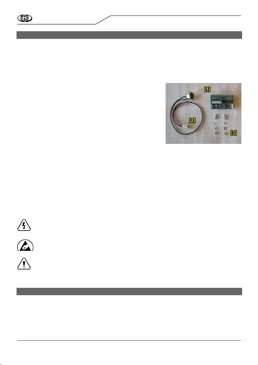
The supplied MIDI interface kit contains all necessary parts, materials,
and detailed installation instructions. The kit contains:
1. MIDI interfac e bo ard
2. Bunched cables with MIDI socket
3. All necessary coupling elements (screws, nuts, washers)
4. Owner’s and Installation manuals in printed form
1.2
1.2 GENERAL INFORMATION
GENERAL INFORMATION
1.21.2
GENERAL INFORMATIONGENERAL INFORMATION
The installation of all interface components is very easy. If yo u follow the instruct ion from this manual there will
be no major problems during the installation procedure. The cover of the instrument will not be markedly
damaged during the installation. The physical appearance of the vintage instrument remains nearly th e same as
before the installation. If n ecessary, th e in terface can be removed an d th e instrument restored back to original
appearance. All original features of the Korg Poly-61 are kept. The instrument can be used the same way as
before the retrofitting.
The following tools are necessary for the installation: Phillips screwdri ver, driller, drills 3,2 and 16 mm, smaller
rasp, pliers, soldering iron (a low heat iron and soldering paste).
Attention !
Attention ! Disconnect the instrument form the mains prior to the installation. Otherwise, there is a
Attention !Attention !
risk of the electric shock!
Attention!
Attention! Observe precautions for handling electrostatic discharge sensitive devices!
Attention!Attention!
Attention!
Attention! The producer is not responsible for any eventual mechanical or electrical damage of the
Attention!Attention!
instrument caused by the infringement of the described installation procedure or by careless
2222 MIDI INTERFACE INSTALLATION
The interface is connected to the keyboard switch matrix of the instrument in a parallel fashion (pic. 1). There
are two versions of instrument’s main PCB board. Older is named KLM475, newer is named KLM-509. Although
some little difference is between t hese boards, the interface i s applicable to both versions of instrument’s main
board.
manipulation during the installation of the MIDI interface!
MIDI INTERFACE INSTALLATION
MIDI INTERFACE INSTALLATIONMIDI INTERFACE INSTALLATION
MIDI Interface for Korg Poly-61 Keyboard
Parts of the MIDI interface kit
Parts of the MIDI interface kit
Parts of the MIDI interface kitParts of the MIDI interface kit
Model 8-435 ver. 1.0
3
All ri ghts re served. No part of t his pub licati on may be rep roduced i n any form without the wri tten permi ssio n of CHD E lektroserv is.
Copyr ight © 2018 CHD E lektroserv is.
Page 4

P61-KBD
MIDI Interface for Korg Poly-61 Keyboard
Pic. 1
Pic. 1 ---- Electrical connection in the instrument
Electrical connection in the instrument
Pic. 1 Pic. 1
Electrical connection in the instrument Electrical connection in the instrument
Model 8-435 ver. 1.0
2.1
2.1 RELEASING OF T
RELEASING OF THE INSTRUMENT COVER
2.12.1
RELEASING OF TRELEASING OF T
a) Unscrew the four screws from the bottom of the instrument (pic. 2.1-1) and the four screws on the front
panel (pic. 2.1-2).
b) Carefully open the instrument - lift off the instrument’s front panel (pic. 2.1-3). Instrument’s main b oard
(KLM475 / KLM-509) is located at left side inside the instrument.
2.2
2.2 MIDI
MIDI----IN SOCKET MONTAGE
2.22.2
There are two possible ways to install the MIDI-IN DIN socket:
If you d o not want to mechanically damage the rear panel of th e instrument, take out the MIDI cable through
the slot on the left side of the keyboard for example (see pic. 2.2-1).
IN SOCKET MONTAGE
MIDIMIDI
IN SOCKET MONTAGEIN SOCKET MONTAGE
HE INSTRUMENT COVER
HE INSTRUMENT COVERHE INSTRUMENT COVER
Pic. 2.1
Pic. 2.1----1111
Pic. 2.1Pic. 2.1
Pic. 2.1
Pic. 2.1
Pic. 2.1----3333
Pic. 2.1Pic. 2.1
Pic. 2.1----2222
Pic. 2.1 Pic. 2.1
4
All ri ghts re served. No part of t his pub licati on may be rep roduced i n any form without the wri tten permi ssio n of CHD E lektroserv is.
Copyr ight © 2018 CHD E lektroserv is.
Page 5

P61-KBD
It is better to place the MIDI-IN connector on the rear panel of the instrument for easier operation. It is
MIDI Interface for Korg Poly-61 Keyboard
Model 8-435 ver. 1.0
necessary to drill three holes in the instrument panel however. The MIDI-IN connector can be installed near
the jack connectors (see pic. 2.2-2). In that case, MIDI-IN connector installation procedure is as follows:
Pic. 2.2
Pic. 2.2----1111
Pic. 2.2Pic. 2.2
Pic. 2.2
Pic. 2.2----2222
Pic. 2.2 Pic. 2.2
a) Flip the front cover over and return it to its original closed position on top of the synth.
b) Drill three ho les (one with 16 mm di ameter and two with 3,5 mm diameter) in the rear panel (see pic. 2.2-3).
Work carefully so as to not drill the parts inside the instrument (pic. 2.2-4).
Pic. 2.2
Pic. 2.2----3333
Pic. 2.2Pic. 2.2
Pic. 2.2
Pic. 2.2----4444
Pic. 2.2 Pic. 2.2
c) Clean the edge of the holes with small rasp (pic. 2.2-5). Also clean the holes from the inside after the
instrument opening..
d) Clean all iron sawdust and raspings from the inside of the instruments
Cle an all ir on sawdust and raspings from the i nside of the instruments
Cle an all ir on sawdust and raspings from the i nside of the instrumentsCle an all ir on sawdust and raspings from the i nside of the instruments
, they can cause short circui ts or se rious
electrical damage if left in the instrument. Please clean the i nstrument carefully!
e) Get flat connector of bunch ed cables (part of the kit) through th e hole in rear panel into the instrument (pic.
2.2-6).
f) Insert the DIN socket into hole i n rear panel (pic. 2.2-7) and fix it to the panel using screws, washers and n uts
(pic. 2.2-8). All material is a part of the kit.
5
All ri ghts re served. No part of t his pub licati on may be rep roduced i n any form without the wri tten permi ssio n of CHD E lektroserv is.
Copyr ight © 2018 CHD E lektroserv is.
Page 6

P61-KBD
Pic. 2.2
Pic. 2.2----5555
Pic. 2.2Pic. 2.2
MIDI Interface for Korg Poly-61 Keyboard
Pic. 2.2
Pic. 2.2----6666
Pic. 2.2 Pic. 2.2
Model 8-435 ver. 1.0
Pic. 2.2
Pic. 2.2----7777
Pic. 2.2Pic. 2.2
Pic. 2.2
Pic. 2.2----8888
Pic. 2.2 Pic. 2.2
f) You may also want to label the M IDI socket ("MIDI - INP UT") using self-adhesive foil, for example (pic. 2.2-2).
2.3
2.3 BUNCHED CABLES MONTAGE
BUNCHED CABLES MONTAGE
2.32.3
BUNCHED CABLES MONTAGEBUNCHED CABLES MONTAGE
Pic. 2.3
Pic. 2.3----1111
Pic. 2.3 Pic. 2.3
The bunched cables (part of
the kit) has a four-pin
connector on one end (pic.
2.3-1). There are four
terminals. Two of them (Nr.
3, Nr. 4) are already fixed
to newly installed D IN MIDI-IN connector. Next
two (Nr. 1, Nr. 2) must be
soldered to the
instrument's K LM-475 /
KLM-509 board (pic. 2.3-2).
6
All ri ghts re served. No part of t his pub licati on may be rep roduced i n any form without the wri tten permi ssio n of CHD E lektroserv is.
Copyr ight © 2018 CHD E lektroserv is.
Page 7

P61-KBD
r
f
r
MIDI Interface for Korg Poly-61 Keyboard
Pic. 2.3
Pic. 2.3----2222
Pic. 2.3Pic. 2.3
Model 8-435 ver. 1.0
d
ace boa
Inte
CN30DCN29P
Bunched
cables
4
MIDI - IN+ (DIN pin Nr. 4)
3
MIDI - IN- (DIN pin Nr. 5)
2
GND (KLM-475 / KLM-509 board)
1
+5V (KLM-475 / KLM-509 board)
MIDI - Input
a) Solder the red cable (Vcc +5V - pin Nr. 1 of interface’s connector) to t he power distribution +5V on the KLM475 / KLM-509 board. The most suitable place is lead (pin) Nr. 14 of the IC3 (pic. 2.3-3).
b) Solder the blue cable (GROUND - pin Nr. 2 of interface’s connector) to the ground potential on the KLM-475 /
KLM-509 board. The most suitable place is is lead (pin) Nr. 7 of the IC3 (pic. 2.3-4).
Pic. 2.3
Pic. 2.3----3333
Pic. 2.3Pic. 2.3
Pic. 2.3
Pic. 2.3----4444
Pic. 2.3 Pic. 2.3
2.4
2.4 INTERFACE BOARD
INTERFACE BOARD PLACEMENT
2.42.4
INTERFACE BOARD INTERFACE BOARD
PLACEMENT
PLACEMENTPLACEMENT
a) Detach bunched cables from CN29P and CN30D connectors on KLM-475 / KLM-509 board These cables lead
from instrument’s keyboard (pic. 2.4-1).
b) Plug interface board onto CN29P and CN30D connectors on KLM-475 / KLM -509 board so that flat four-pin
plug on interface’s board is to right (pic. 2.4-2).
c) Plug the connectors of the bunched cables from the keyboard onto the plugs on the interface’s board (pic.
2.4-3). Be careful, the connectors must not be rotated or exchanged. Locks of the connectors must be down.
Bunched cables with black and white colored wires are left (CN29P connector) and bunched cables with yellow
and white colored wires are right (CN30D connector).
d) Plug the flat 4-pin connector of newly installed bunched cables (from +5V, GND and MIDI-IN socket) to the
flat connector on the MIDI-In interface board (pic. 2.4-4). The connector is shaped such that it cannot be
connected the wrong way - there are locks on it.
7
All ri ghts re served. No part of t his pub licati on may be rep roduced i n any form without the wri tten permi ssio n of CHD E lektroserv is.
Copyr ight © 2018 CHD E lektroserv is.
Page 8

P61-KBD
Pic. 2.4
Pic. 2.4----1111
Pic. 2.4Pic. 2.4
MIDI Interface for Korg Poly-61 Keyboard
Pic. 2.4
Pic. 2.4----2222
Pic. 2.4 Pic. 2.4
Model 8-435 ver. 1.0
Pic. 2.4
Pic. 2.4----3333
Pic. 2.4Pic. 2.4
2.5
2.5 INSTRUMENT RE
INSTRUMENT RE----ASSEMBLY
2.52.5
INSTRUMENT REINSTRUMENT RE
ASSEMBLY
ASSEMBLYASSEMBLY
Pic. 2.4
Pic. 2.4----4444
Pic. 2.4 Pic. 2.4
a) Turn over the front panel of the instrument.
b) Reattach the front panel to the sides of the instrument with four screws (pic. 2.5-1) and reattach four screws
to the bottom of the cover (pic. 2.5-2). This is the reverse procedure of that described in the chapter 2.1.
Pic. 2.5
Pic. 2.5----1111
Pic. 2.5Pic. 2.5
Pic. 2.5
Pic. 2.5----2222
Pic. 2.5Pic. 2.5
The installation of the MIDI kit is now finished, the instrument is ready for use with MIDI. Please read the user’s
manual carefully before the MIDI interface usage.
8
All ri ghts re served. No part of t his pub licati on may be rep roduced i n any form without the wri tten permi ssio n of CHD E lektroserv is.
Copyr ight © 2018 CHD E lektroserv is.
 Loading...