


SETUP INSTRUCTIONS
FN-113
FINISHER
Di551/Di650
NOTES
•Keep all packing materials out of the reach of children.
•Before setting up, be sure to unplug the power cord of the machine.
4698-7744-03 |
© MINOLTA CO., LTD. |
Printed in Japan |
|
|
|
|
|
|

FINISHER
■ Components |
|
|
|
|
Remove tape and fixing brackets. |
1. |
Feeder Attachment.................................................................................. |
1 |
2. |
Pipe ......................................................................................................... |
1 |
3. |
Fixing Bracket.......................................................................................... |
2 |
4. |
Ground Plate ........................................................................................... |
1 |
5. |
Tray ......................................................................................................... |
1 |
6. |
Wire Form................................................................................................ |
1 |
7. |
Label........................................................................................................ |
2 |
8. |
Screw ...................................................................................................... |
8 |
9. |
Setup Instructions.................................................................................... |
1 |
10. |
Cover ....................................................................................................... |
1 |
: Tape
1.Open the vertical transport section of the Finisher and remove tape and fixing brackets from the Stapling Unit.
1
 2
2 

 3
3
4698U019AA C4611U005AA 4698U002AA
|
|
|
5 |
4 |
|
|
|
4698U003AA |
|
4643U006AA |
|
|
|
|
|
|
6 |
7 |
8 |
|
|
||
|
|
|
|
|
|
|
9646-0408-13 |
4643U010AA |
|
4643U032AA |
|
4698U004AA
NOTE
Do not remove this part.
Use a mini-screwdriver to remove this fixing bracket.
Cushion
4643U005AA
4698U020AA
4643U003AA
4698-7744-03 |
– 1 – |
FINISHER
NOTES
•Make sure that the Finisher is installed on a level surface.
•Once the Finisher has been installed, do not move it unless absolutely necessary. If it becomes absolutely necessary to move the Finisher, remove the Pipe both from it and the machine. After the Finisher has been relocated, attach the Pipe back again by following the steps given in “Attaching the Pipe.”
•When moving the Finisher, press the side opposite to the Tray to prevent the Finisher from toppling over.
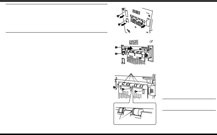
■ Attaching the Positioning Pin, Fixing Brackets, and Pipe
1. Remove the Left Covers (at three locations) of the machine.
4698U021AA
2. Install Fixing Bracket A.
4698U022AA
Exit Rollers |
3. Remove the Exit Roller Cover (three |
|
screws). |
4. Cut the inner Treaded Rubber Collars (4pcs.) of each Exit Roller.
5. Reinstall the Exit Roller Cover (three screws) which has been removed in step 3.
NOTE
Make sure that the cover is doweled into position.
Inner Side
4698U115AB
4698-7744-03 |
– 2 – |
 Loading...