


EEAM010300
Operation &
Maintenance Manual
PC290LC-6K
PC290NLC-6K
HYDRAULIC EXCAVATOR
SERIAL NUMBER |
PC290LC-6K - |
K30001 and up |
|
PC290NLC-6K - |
K30001 and up |
|
Including 2 piece boom |
|
WARNING
Unsafe use of this machine may cause serious injury or death. Operators and maintenance personnel must read this manual before operating or maintaining this machine. This manual should be kept inside the cab for reference and periodically reviewed by all personel who will come into contact with the machine.

1. FOREWORD
This manual provides rules and guidelines which will help you use this machine safely and effectively. Keep this manual handy and have all personnel read it periodically. If this manual has been lost or has become dirty and can not be read, request a replacement manual from Komatsu or your Komatsu distributor.
If you sell the machine, be sure to give this manual to the new owners.
Continuing improvements in the design of this machine can lead to changes in detail which may not be reflected in this manual. Consult Komatsu or your Komatsu distributor for the latest available information for your machine or for questions regarding information in this manual.
WARNING
•This operation & maintenance manual may contain attachments and optional equipment that are not available in your area. Please consult your local Komatsu distributor for those items you require.
•This machine complies with EC directive (89/392/EEC ).
Machines complying with this directive display the CE mark
•Improper operation and maintenance of this machine can be hazardous and could result in serious injury or death.
•Operators and maintenance personnel should read this manual thoroughly before beginning operation or maintenance.
•Some actions involved in operation and maintenance of the machine can cause a serious accident, if they are not done in a manner described in this manual.
•The procedures and precautions given in this manual apply only to intended uses of the machine. If you use your machine for any unintended uses that are not specifically prohibited, you must be sure that it is safe for you and others. In no event should you or others engage in prohibited uses or actions as described in this manual.
•Komatsu delivers machines that comply with all applicable regulations and standards of the country to which it has been shipped. If this machine has been purchased in another country or purchased from someone in another country, it may lack certain safety devices and specifications that are necessary for use in your country. If there is any question about whether your product complies with the applicable standards and regulations of your country, consult Komatsu or your Komatsu distributor before operating the machine.
•The description of safety is given in SAFETY INFORMATION on page 0-2 and in SAFETY from page 1-1.
PC290-ENG
0-1

2. SAFETY INFORMATION
2.1 SAFETY MESSAGES
Most accidents are caused by the failure to follow fundamental safety rules for the operation and maintenance of machines.
To avoid accidents, read, understand and follow all precautions and warnings in this manual and on the machine before performing operation and maintenance.
To identify hazards on the machine pictorial decals are used ( see POSITION FOR ATTACHING SAFETY LABELS).
RED WARNING TRIANGLE |
- This is used on safety labels where there is a high probability |
|
|
|
of serious injury or death if the hazard is not avoided. These |
|
|
safety messages or labels usually describe precautions that |
|
|
must be taken to avoid the hazard. Failure to avoid this hazard |
|
|
may also result in serious damage to the machine. |
ORANGE WARNING TRIANGLE |
- |
This is used on safety labels where there is a potentially |
|
|
dangerous situation which could result in serious injury or |
|
|
death if the hazard is not avoided. These safety messages or |
|
|
labels usually describe precautions that must be taken to |
|
|
avoid the hazard. Failure to avoid this hazard may also result |
|
|
in serious damage of the machine |
YELLOW SAFETY TRIANGLE |
- |
This is used on safety labels for hazards which could result in |
|
|
minor or moderate injury if the hazard is not avoided. This |
|
|
word might also be used for a hazard where the only result |
|
|
could be damage to the machine. |
NOTICE |
- |
This word is used for precautions that must be taken to avoid |
|
|
actions which could shorten the life of the machine. |
Safety precautions are described in SAFETY from page 1-1.
Komatsu cannot predict every circumstance that might involve a potential hazard in operation and maintenance. Therefore the safety message in this manual and on the machine may not include all possible safety precautions. If any procedures or actions not specifically recommended or allowed in this manual are used, you must be sure that you and others can do such procedures and actions safely and without damaging the machine. If you are unsure about the safety of some procedures, contact Komatsu or your Komatsu distributor.
0-2
PC290-ENG

2. SAFETY INFORMATION
2.2. NOISE
Operator ears noise value |
Ambient noise value |
(Sound pressure level) |
(Sound power level) |
95/27/EC |
95/27/EC |
Noise level indicated is the guaranteed value as specified in the directive 86/662/EEC, as amended by 95/27/EEC
2.3. VIBRATION
•The weighted root mean square acceleration value to which the operator’s arms are subjected does not exceed 2.5 m/s
•The weighted root mean square acceleration value to which the operator’s body is subjected does not exceed 0.5 m/s
These results were obtained by accelerometers during trench digging.
PC290-ENG
0-3

3. INTRODUCTION
3.1 INTENDED USE
This Komatsu HYDRAULIC EXCAVATOR is designed to be used mainly for the following work:
•Digging
•Smoothing work
•Ditching work
•Loading work
See the section 12.14 “WORK POSSIBLE USING HYDRAULIC EXCAVATOR” for futher details
3.2FEATURES
•This Komatsu HYDRAULIC EXCAVATOR is equipped with various controls based on an advanced electronics system.
•The monitor panel greatly facilitates daily maintenance and self-diagnosis.
•Working mode, travel speed and swing priority are selectable.
•Digging and lifting force can be increased by light-touch control. (For details, see operation section.)
•Adjustable wrist control levers make operations smooth and easy.
•Fresh filtered air heater assures comfortable operation. (Air conditioner option)
•Low noise level and smart urban style design and colouring.
•Superb operation performance provided by powerful engine and high-performance hydraulic pumps.
•Low fuel consumption controlled by an electronic control system provides an environment-friendly machine.
3.3BREAKING IN YOUR NEW MACHINE
Your Komatsu machine has been thoroughly adjusted and tested before shipment.
However, operating the machine under severe conditions at the beginning can adversely affect the performance and shorten the machine life.
Be sure to break in the machine for the initial 100 hours (as indicated by the hour meter.) During breaking in:
•Idle the engine for 5 minutes after starting it up.
•Avoid operation with heavy loads or at high speeds.
•Sudden starting or acceleration, unnecessarily abrupt braking and sharp turning should be avoided except in cases of emergency.
Additionally for the first 20 hours
•Avoid operating engine for prolonged periods at constant speed (including idle.)
•Avoid high speed travelling for periods of more than 5 minutes.
Pay particular attention to oil pressure and temperature indicators & check coolant and oil levels frequently during breaking in.
The precautions given in this manual for operating, maintenance, and safety procedures are only those that apply when this product is used for the specified purpose. If the machine is used for a purpose that is not listed in this manual, Komatsu cannot bear any responsibility for safety. All consideration of safety in such operations is the responsibility of the user.
Operation that are prohibited in this manual must never carried out under any circumstances.
0-4
PC290-ENG
4.LOCATION OF PLATES, TABLE TO ENTER SERIAL NO. AND DISTRIBUTOR
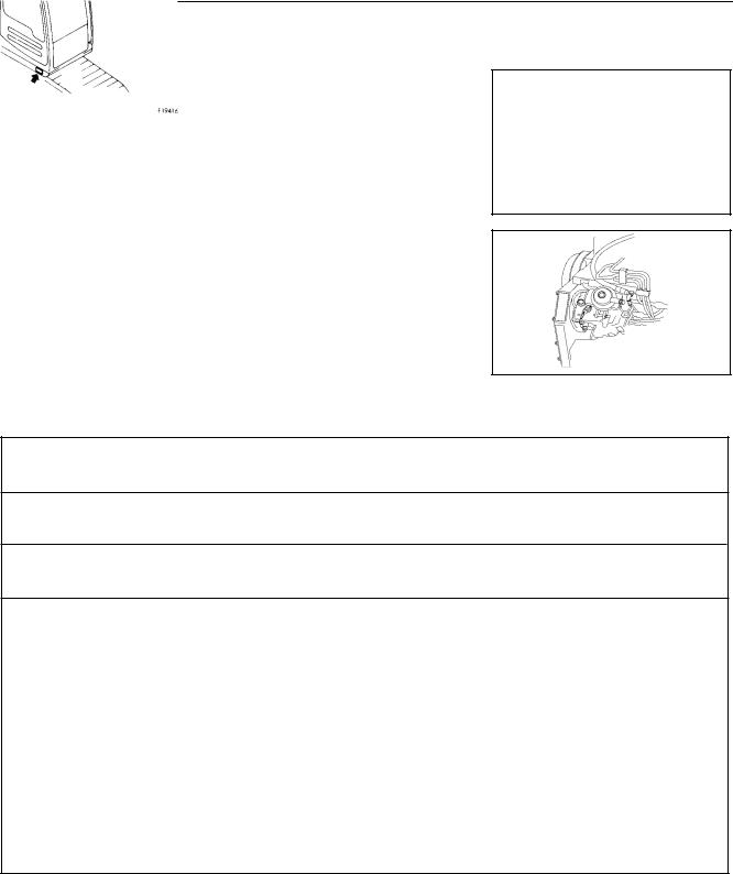
4.1 MACHINE SERIAL NO. PLATE POSITION
On the front bottom right of the operator’s cab
4.2 ENGINE SERIAL NO. PLATE POSITION
On the upper side of the engine cylinder head cover
4.3 TABLE TO ENTER SERIAL NO. AND DISTRIBUTOR
Machine serial No.:
Engine serial No.:
Attachment serial No.:
Manufacturers name: |
Komatsu UK Ltd |
Address |
Durham Road |
|
Birtley |
|
Chester-Le-Street |
|
County Durham DH32QX |
|
United Kingdom |
Distributor |
|
Address |
Phone |
PC290-ENG
0-5

4.4 MACHINE SERIAL PLATE.
MODEL
SERIAL No
MANUFACTURING YEAR
WEIGHT
ENGINE POWER
MANUFACTURER
Produced by Komatsu UK Ltd. for Komatsu Ltd, Tokyo, Japan.
0-6
PC290-ENG

5. CONTENTS
PC290-ENG
1. |
FOREWORD ...................................................................................................................................... |
0-1 |
2. |
SAFETY INFORMATION ................................................................................................................... |
0-2 |
3. |
INTRODUCTION ............................................................................................................................... |
0-4 |
4. |
LOCATION OF PLATES, TABLE TO ENTER SERIAL NO. AND DISTRIBUTOR ............................. |
0-5 |
SAFETY
6. |
GENERAL PRECAUTIONS ............................................................................................................... |
1-2 |
|
7. |
PRECAUTIONS DURING OPERATION ............................................................................................ |
1-8 |
|
|
7.1 |
Before starting engine .................................................................................................................. |
1-8 |
|
7.2 |
Operating machine ..................................................................................................................... |
1-10 |
|
7.3 |
Transportation ............................................................................................................................ |
1-15 |
|
7.4 |
Battery ........................................................................................................................................ |
1-16 |
|
7.5 |
Towing ........................................................................................................................................ |
1-17 |
|
7.6 |
Bucket with hook ........................................................................................................................ |
1-18 |
8. |
PRECAUTIONS FOR MAINTENANCE ........................................................................................... |
1-21 |
|
|
8.1 |
Before carrying out maintenance ............................................................................................... |
1-21 |
|
8.2 |
During maintenance ................................................................................................................... |
1-24 |
9. |
POSITION FOR ATTACHING SAFETY LABELS ............................................................................. |
1-28 |
|
OPERATION
10. |
GENERAL VIEW |
|
|
|
10.1 |
General view of machine .......................................................................................................... |
2-2 |
|
10.2 |
General view of controls and gauges ........................................................................................ |
2-3 |
11. |
EXPLANATION OF COMPONENTS |
|
|
|
11.1 |
Machine monitor ....................................................................................................................... |
2-4 |
|
11.2 |
Meter ...................................................................................................................................... |
2-15 |
|
11.3 |
switches ................................................................................................................................. |
2-16 |
|
11.4 |
Control levers, pedals ............................................................................................................ |
2-20 |
|
11.5 |
Ceiling window ....................................................................................................................... |
2-25 |
|
11.6 |
Front window .......................................................................................................................... |
2-26 |
|
11.7 |
Door lock ................................................................................................................................ |
2-28 |
|
11.8 |
Cap, cover with lock ............................................................................................................... |
2-29 |
|
11.9 |
Luggage tray .......................................................................................................................... |
2-30 |
|
11.10 Ashtray ................................................................................................................................... |
2-30 |
|
|
11.11 Heater ..................................................................................................................................... |
2-30 |
|
|
11.12 Air conditioner ........................................................................................................................ |
2-31 |
|
|
11.13 |
Car radio ................................................................................................................................ |
2-34 |
|
11.14 |
Fuse ....................................................................................................................................... |
2-35 |
|
11.15 |
Fusible link ............................................................................................................................. |
2-36 |
|
11.16 |
Controllers .............................................................................................................................. |
2-36 |
|
11.17 Tool box .................................................................................................................................. |
2-36 |
|
|
11.18 |
Refuelling pump ..................................................................................................................... |
2-36 |
|
11.19 |
Handling the accumulator ...................................................................................................... |
2-37 |
0-7

5. CONTENTS
12. |
OPERATION |
|
||
|
12.1 |
|
Check before starting engine ................................................................................................. |
2-39 |
|
12.2 |
|
Starting engine ....................................................................................................................... |
2-49 |
|
12.3 |
|
Operations and checks after starting engine ......................................................................... |
2-52 |
|
12.4 |
|
Moving machine off ................................................................................................................ |
2-58 |
|
12.5 |
|
Steering machine ................................................................................................................... |
2-61 |
|
12.6 |
|
Stopping machine .................................................................................................................. |
2-63 |
|
12.7 |
|
Swinging ................................................................................................................................ |
2-64 |
|
12.8 |
|
Operation of work equipment ................................................................................................. |
2-65 |
|
12.9 |
|
Handling active mode ............................................................................................................. |
2-66 |
|
12.10 |
Working mode selection ....................................................................................................... |
2-68 |
|
|
12.11 Prohibitions for operation ...................................................................................................... |
2-70 |
||
|
12.12 |
Precaution for operation ........................................................................................................ |
2-72 |
|
|
12.13 |
Precaution when travelling up or down hills .......................................................................... |
2-73 |
|
|
12.14 |
How to escape from mud ...................................................................................................... |
2-75 |
|
|
12.15 |
Work possible using hydraulic excavator .............................................................................. |
2-76 |
|
|
12.16 |
Replacement and inversion of bucket ................................................................................... |
2-77 |
|
|
12.17 |
Parking the machine ............................................................................................................. |
2-79 |
|
|
12.18 |
Check after finishing work ...................................................................................................... |
2-80 |
|
|
12.19 |
Stopping engine ..................................................................................................................... |
2-81 |
|
|
12.20 |
Check after stopping engine .................................................................................................. |
2-82 |
|
|
12.21 |
Locking ................................................................................................................................... |
2-82 |
|
|
12.22 |
Overload warning device ....................................................................................................... |
2-82 |
|
13 |
TRANSPORTATION |
|
||
|
13.1 |
|
Loading, unloading work ......................................................................................................... |
2-83 |
|
13.2 |
|
Precautions for loading ........................................................................................................... |
2-85 |
|
13.3 |
|
Precautions for transportation ................................................................................................. |
2-86 |
|
13.4 |
|
Lifting the machine .................................................................................................................. |
2-86 |
14. |
COLD WEATHER OPERATION |
|
||
|
14.1 |
|
Precaution for low temperature ............................................................................................... |
2-87 |
|
14.2 |
|
Precautions after completion of work ...................................................................................... |
2-89 |
|
14.3 |
After cold weather ................................................................................................................... |
2-89 |
|
15. |
LONG-TERM STORAGE |
|
||
|
15.1 |
|
Before storage ........................................................................................................................ |
2-90 |
|
15.2 |
|
Posture when leaving machine ............................................................................................... |
2-90 |
|
15.3 |
|
During storage ........................................................................................................................ |
2-91 |
|
15.4 |
After storage ............................................................................................................................ |
2-91 |
|
|
15.5 |
|
Starting machine after long-term storage ................................................................................ |
2-91 |
16. |
TROUBLESHOOTING |
|
||
|
16.1 |
|
Phenomena that are not failures ............................................................................................. |
2-92 |
|
16.2 |
|
Method of towing machine ...................................................................................................... |
2-92 |
|
16.3 |
|
Using method for light-weight towing hole .............................................................................. |
2-92 |
|
16.4 |
|
Precautions on particular jobsites ........................................................................................... |
2-93 |
|
16.5 |
|
If battery is discharged ............................................................................................................ |
2-93 |
|
16.6 |
|
Other trouble ........................................................................................................................... |
2-97 |
0-8
PC290-ENG
5. CONTENTS
PC290-ENG
MAINTENANCE
17. |
GUIDES TO MAINTENANCE ............................................................................................................ |
3-2 |
|
18. |
OUTLINES OF SERVICE .................................................................................................................. |
3-5 |
|
|
18.1 |
Outline of oil, fuel, coolant ........................................................................................................ |
3-5 |
|
18.2 |
Outline of electric system ......................................................................................................... |
3-9 |
|
18.3 |
Outline of hydraulic system .................................................................................................... |
3-10 |
19. |
WEAR PARTS LIST .......................................................................................................................... |
3-11 |
|
20. |
USE OF FUEL, COOLANT AND LUBRICANTS ACCORDING TO AMBIENT TEMPERATURE ..... |
3-12 |
|
|
PRECAUTIONS WHEN HANDLING ............................................................................................... |
3-17 |
|
|
TESTING AND ADJUSTING ............................................................................................................ |
3-19 |
|
|
PERIODIC MAINTENANCE ............................................................................................................ |
3-20 |
|
21. |
STANDARD TIGHTENING TORQUES FOR BOLTS AND NUTS ................................................... |
3-21 |
|
|
21.1 |
Introduction of necessary tools ............................................................................................... |
3-21 |
|
21.2 |
Torque list ................................................................................................................................ |
3-22 |
22. |
PERIODIC REPLACEMENT OF SAFETY CRITICAL PARTS ......................................................... |
3-23 |
|
23. |
MAINTENANCE SCHEDULE CHART ............................................................................................. |
3-26 |
|
|
23.1 |
Maintenance schedule chart ................................................................................................... |
3-26 |
|
23.2 |
Maintenance interval when using hydraulic breaker ............................................................... |
3-28 |
24. |
SERVICE PROCEDURE ................................................................................................................. |
3-29 |
|
|
24.1 |
Initial 250 hours service .......................................................................................................... |
3-29 |
|
24.2 |
When required ........................................................................................................................ |
3-30 |
|
24.3 |
Check before staring ............................................................................................................... |
3-46 |
|
24.4 |
Every 100 hours service ......................................................................................................... |
3-51 |
|
24.5 |
Every 250 hours service ......................................................................................................... |
3-55 |
|
24.6 |
Every 500 hours service ......................................................................................................... |
3-59 |
|
24.7 |
Every 1000 hours service ....................................................................................................... |
3-65 |
|
24.8 |
Every 2000 hours service ....................................................................................................... |
3-68 |
|
24.9 |
Every 4000 hours service ....................................................................................................... |
3-71 |
|
24.10 Every 5000 hours service ...................................................................................................... |
3-72 |
|
SPECIFICATIONS
25. MACHINE SPECIFICATIONS ............................................................................................................ |
4-2 |
|
25.1 |
Machine specifications .............................................................................................................. |
4-2 |
25.2 |
Explanation of lifting capacity chart ........................................................................................... |
4-6 |
TRANSPORTATION .......................................................................................................................... |
4-9 |
|
COMPONENTS DIMENSIONS AND WEIGHTS (Approximate) • (Two Piece Boom) ..................... |
4-10 |
|
0-9

5. CONTENTS
OPTIONS AND ATTACHMENTS
26 |
GENERAL PRECAUTIONS ............................................................................................................... |
5-2 |
|
|
26.1 |
General precautions related to safety ........................................................................................ |
5-2 |
|
26.2 |
Precautions when installing attachments ................................................................................... |
5-3 |
27. |
HANDLING BUCKET WITH HOOK ................................................................................................... |
5-4 |
|
|
27.1 |
Checking for damage to bucket with hook ................................................................................. |
5-4 |
|
27.2 |
Prohibited operations ................................................................................................................. |
5-4 |
|
27.3 |
Precautions during operation ..................................................................................................... |
5-4 |
28 |
MACHINE READY FOR ATTACHMENTS ......................................................................................... |
5-5 |
|
|
28.1 |
Explanation of components ........................................................................................................ |
5-5 |
|
28.2 |
Hydraulic circuit .......................................................................................................................... |
5-7 |
|
28.3 Attachment mounting / dismounting procedure .......................................................................... |
5-9 |
|
|
28.4 |
Operation .................................................................................................................................. |
5-11 |
|
28.5 |
Long-term storage .................................................................................................................... |
5-12 |
|
28.6 |
Specifications ........................................................................................................................... |
5-12 |
|
28.7 |
First attachment with clam-shell option ................................................................................. |
5-12-1 |
|
28.8 |
First and second attachment ................................................................................................. |
5-12-2 |
29. |
INTRODUCTION OF ATTACHMENTS ............................................................................................ |
5-13 |
|
|
29.1 |
Specification, use ..................................................................................................................... |
5-13 |
|
29.2 Attachment installing combination table ................................................................................... |
5-14 |
|
|
29.3 |
Selection of track shoes ........................................................................................................... |
5-15 |
|
29.4 |
Selection of bucket teeth .......................................................................................................... |
5-16 |
|
29.5 |
Handling trapezoidal bucket ..................................................................................................... |
5-17 |
|
29.6 |
Using the extension arm .......................................................................................................... |
5-18 |
|
29.7 |
Handling the clamshell bucket ................................................................................................. |
5-19 |
30. |
EXTENDING MACHINE SERVICE LIFT ......................................................................................... |
5-20 |
|
|
30.1 |
Hydraulic breaker ..................................................................................................................... |
5-20 |
|
30.2 |
Power ripper ............................................................................................................................. |
5-23 |
|
30.3 |
Fork grab .................................................................................................................................. |
5-24 |
|
30.4 |
Grapple bucket ......................................................................................................................... |
5-25 |
|
30.5 |
Scrap grapple ........................................................................................................................... |
5-26 |
|
30.6 |
Crusher & cutter ....................................................................................................................... |
5-27 |
|
30.7 |
Hydraulic pile driver ................................................................................................................. |
5-28 |
|
30.8 |
Hydraulic excavator with multi-purpose crane ......................................................................... |
5-29 |
0-10
PC290-ENG

SAFETY
WARNING
Read and follow all safety precautions. Failure to do so may result in serious injury or death.
This safety section also contains precautions for optional equipment and attachments.
PC290-ENG
1-1

6. GENERAL PRECAUTIONS
 WARNING: For reasons of safety, always follow these safety precautions.
 SAFETY RULES
•ONLY trained and authorised personnel can operate and maintain the machine.
•Follow all safety rules, precautions and instructions when operating or performing maintenance on the machine.
•When working with another operator or a person on worksite traffic duty, be sure all personnel understand all hand signals that are to be used.
 SAFETY FEATURES
•Be sure all guards and covers are in their proper position. Have guards and covers repaired if damaged.
•Use safety features such as safety lock lever properly.
•NEVER remove any safety features. ALWAYS keep them in good operating condition.
Safety lever n See 12.16 “PARKING THE MACHINE”.
•Improper use of safety features could result in serious bodily injury or death.
 CLOTHING AND PERSONAL PROTECTIVE ITEMS
•Avoid loose clothing, jewellery, and loose long hair. They can catch on controls or in moving parts and cause serious injury or death. Also, do not wear oily cloths because they are flammable.
•Wear a hard hat, safety glasses, safety shoes, mask or gloves when operating or maintaining the machine. Always wear safety goggles, hard hat and heavy gloves if your job involves scattering metal chips or minute materials <—> this is so particularly when driving pins with a hammer and when cleaning the air cleaner element with compressed air.
Check also that there is no one near the machine.
Driving in pins, See n 12.15 “REPLACEMENT AND INVERSION OF BUCKET’. Cleaning of air cleaner element, See n 24.2 “WHEN REQUIRED” in service procedure.
1-2
PC290-ENG
WARNING: Failure to follow these safety |
|
precautions may lead to a serious accident. |
6. GENERAL PRECAUTIONS |
PC290-ENG
 UNAUTHORISED MODIFICATION
•Any modification made without authorisation from Komatsu can create hazards.
•Before making a modification, consult your Komatsu distributor. Komatsu will not be responsible for any injury or damage caused by any unauthorised modification.
 ALWAYS APPLY LOCK WHEN LEAVING OPERATOR’S SEAT
•When standing up from the operator’s seat, always place the safety lock lever securely in the LOCK position. If you accidentally touch the travel or swing lever when they are not locked, the work equipment may suddenly move and cause serious injury or damage.
•When leaving the machine, lower the work equipment completely to the ground, set the safety lock lever to the LOCK position, then stop the engine and use the key to lock all the equipment. Always take the key with you. Work equipment posture See n 12.16 “PARKING THE MACHINE.”
 MOUNTING AND DISMOUNTING
•NEVER jump on or off the machine. NEVER get on or off a moving machine.
•When mounting or dismounting, always face the machine and use the handrails, machine or track frame steps, and track shoes.
•Do not hold any control levers when getting on or off the machine.
•Ensure safety by always maintaining at least three-point contact of hands and feet with the handrails, steps or track shoes.
•Always remove any oil or mud from the handrails, steps and track shoes. If they are damaged, repair them and tighten any loose bolts.
•If grasping the door handrail when mounting or dismounting or moving on the track, open and lock the door securely in the open position. Otherwise, the door may move suddenly, causing you to lose balance and fall.
1-3
|
WARNING: For reasons of safety, al- |
6. GENERAL PRECAUTIONS |
ways follow these safety precautions. |
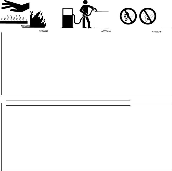
 FIRE PREVENTION FOR FUEL AND OIL
Fuel, oil, and antifreeze can be ignited by a flame. Fuel is particularly FLAMMABLE and can be HAZARDOUS.
•Keep flames away from flammable fluids.
•Stop the engine and do not smoke when refuelling.
•Tighten all fuel and oil caps securely.
•Refuelling and oiling should be carried out in well ventilated areas.
•Keep oil and fuel in a secure place and do not allow unauthorised persons to enter.
 PRECAUTIONS WHEN HANDLING AT HIGH TEMPERATURES
•Immediately after operations are stopped, the engine coolant, engine oil, and hydraulic oil are at high temperatures, and are still under pressure. Attempting to remove the cap, drain the oil or water, or replace the filters may lead to serious burns. Always wait for the temperature to go down, and follow the specified procedures when carrying out these operations.
•To prevent hot water from spurting out:
1)Turn engine off.
2)Allow water to cool.
3)Slowly loosen cap to relieve pressure before removing.
•To prevent hot oil from spurting out:
1)Turn engine off.
2)Allow oil to cool.
3) Slowly loosen cap to relieve pressure before removing.
1-4
PC290-ENG

WARNING: Failure to follow these safety |
|
precautions may lead to a serious accident. |
6. GENERAL PRECAUTIONS |
PC290-ENG
 ASBESTOS DUST HAZARD PREVENTION
Asbestos dust can be HAZARDOUS to your health if it is inhaled.
Your Komatsu machine and genuine Komatsu spare parts do not contain any asbestos. Use only genuine Komatsu spare parts. If spare parts containing asbestos are used, the following precautions must be observed:
•NEVER use compressed air for cleaning.
•Use water for cleaning to keep down the dust.
•Operate the machine with the wind to your back, whenever possible.
•Use an approved respirator if necessary.
CRUSHING OR CUTTING PREVENTION
•Do not enter, or put your hand or arm or any other part of your body between movable parts such as between the work equipment and cylinders, or between the machine and work equipment.
If the work equipment is operated, the clearance will change and this may lead to serious damage or personal injury.
FIRE EXTINGUISHER AND FIRST AID KIT
•Know how to use fire extinguisher (if installed).
•Provide a first aid kit at the storage point.
•Know what to do in the event of a fire.
•Be sure you know the phone numbers of persons you should contact in case of an emergency.
1-5

|
WARNING: For reasons of safety, al- |
6. GENERAL PRECAUTIONS |
ways follow these safety precautions. |
 PROTECTION AGAINST FALLING OR FLYING OBJECTS
If there is any danger of falling or flying objects hitting the operator, install protective guards in place to protect the operator as required for each particular situation.
•For work with breakers, install a front guard on the windshield. Also, place a laminate coating sheet over the windshield.
•For demolition or shear work, install a front guard on the windshield and a top guard on the cab. Also, place a laminate coating sheet over the windshield.
•For work in mines, quarries, demolition, tunnels or other places where there is danger of falling rocks, put FOPS (falling object protective structure) in place. Also, place a laminate coating sheet over the windshield.
The above comments are made with regards to typical working conditions. By all means you should put on other guards if required by conditions at your particular site.
For details of safety guards, please contact your Komatsu distributor.
Also, even for other types of work, if there is any danger of being hit by falling or flying objects or of objects entering the operator’s cab, select and install a guard that matches the working conditions.
Be sure to close the front window before commencing work.
When carrying out the above operations, make sure to keep all persons other than the operator outside the range of falling or flying objects. Be particularly sure to maintain a proper distance when carrying out shear operations.
Level 1 acceptance is intended for protection from small falling rocks, flying objects and other debis encountered in operations such as highway maintenance, landscaping and light construction site services.
Level 1 Guards |
Fitted directly onto the roof and front of the cab. |
Level 2 acceptance is intended for protection from large falling rocks, flying objects and other debris encountered in applications such as demolition work, building construction and general heavy site work.
Level 2 Guards |
Fops fitted directly to the revolving frame. |
|
Front guard fitted directly to front of fops. |
Note: The above guards are the minimum required for typical working conditions as described above and are in accordance with the lastest requirements of ISO/ DIS 10262 (draft standard).
1-6
PC290-ENG

WARNING: Failure to follow these safety |
|
precautions may lead to a serious accident. |
6. GENERAL PRECAUTIONS |
PC290-ENG
PRECAUTIONS FOR ATTACHMENTS
•When installing and using an optional attachment, read the instruction manual for the attachment and the information related to attachments in this manual.
•Do not use attachments that are not authorised by Komatsu or your Komatsu distributor. Use of unauthorised attachments could create a safety problem and adversely affect the proper operation and useful life of the machine.
•Any injuries, accidents, product failures resulting from the use of unauthorised attachments will not be the responsibility of Komatsu.
MACHINES WITH ACCUMULATOR
On machines equipped with an accumulator, for a short time after the engine is stopped, the work equipment will lower under its own weight when the work equipment control lever is shifted to LOWER. After the engine is stopped, set the safety lock lever to the lock position (and also lock the attachment pedal with the lock pin).
When releasing the pressure inside the work equipment circuit on machines equipped with an accumulator, follow the procedure given in the inspection and maintenance section.
Method of releasing pressure n See 11.19 “HANDLING THE ACCUMULATOR’’.
The accumulator is filled with high-pressure nitrogen gas, and it is extremely dangerous if it is handled in the wrong way. Always observe the following precautions.
•Never make any hole in the accumulator or expose it to flame or fire.
•Do not weld anything to the accumulator.
•When carrying out disassembly or maintenance of the accumulator, or when disposing of the accumulator, it is necessary to release the gas from the accumulator. A special air bleed valve is necessary for this operation, so please contact your Komatsu distributor.
Gas in accumulator n See 11.19 “HANDLING THE ACCUMULATOR’’.
 EMERGENCY EXIT
•When exit by normal means is prevented in an emergency you can get out through the emergency exit (rear window).
•Pull the ring at the bottom of the window and remove strip. This will allow you to push out glass.
ROTATING BEACON (OPTION)
•When the machine is operated on or beside a road, a rotating beacon is required to avoid a traffic accident.
•Contact your Komatsu distributor to install beacon lamp.
ELECTROMAGNETIC INTERFERENCE
When this machine is operating close to a source of high electromagnetic interference, such as a radar station, some abnormal phenomena may be observed.
•The display on the monitor panel may behave erratically.
•The warning buzzer may sound.
These effects do not signify a malfunction and the machine will return to normal as soon as the source of interference is removed
1-7

7. PRECAUTIONS DURING OPERATION
7.1 BEFORE STARTING ENGINE
SAFETY AT WORKSITE
•Before starting the engine, thoroughly check the area for any unusual conditions that could be dangerous.
•Before starting the engine, examine the terrain and soil conditions of the worksite. Determine the best and safest method of operation.
•Make the slope as horizontal as possible before continuing operations.
•If you need to operate on a street, protect pedestrians and cars by designating a person for worksite traffic duty or by installing fences around the worksite.
•If water lines, gas lines, and high-voltage electrical lines may be buried under the worksite, contact each utility and identify their locations. Be careful not to sever or cut any of these lines.
•Check the depth and flow of water before operating in water or crossing a river. NEVER be in water which is in excess of the permissible water depth.
Permissible water depth
See n 12.11 “PRECAUTIONS FOR OPERATION.”
 FIRE PREVENTION
•Thoroughly remove wood chips, leaves, paper and other flammable things accumulated on the engine compartment. They could cause a fire.
•Check fuel, lubrication, and hydraulic systems for leaks. Have any leaks repaired. Wipe up any excess oil, fuel or other flammable fluids.
Check point n See 12.1.1 “WALK-AROUND CHECK.”
•Be sure a fire extinguisher is present and working.
IN OPERATOR’S CAB
•Do not leave tools or spare parts lying around in the operator’s compartment. They may damage or break the control levers or switches. Always put them in the tool box on the left side of the machine.
•Keep the cab floor, controls, steps and handrails free of oil, grease, snow, and excess dirt.
1-8
PC290-ENG

WARNING: Failure to follow these safety |
|
precautions may lead to a serious accident. |
7. PRECAUTIONS DURING OPERATION |
PC290-ENG
 VENTILATION FOR ENCLOSED AREAS
•If it is necessary to start the engine within an enclosed area,
provide adequate ventilation. Exhaust fumes from the engine can KILL.
 PRECAUTIONS FOR MIRRORS, WINDOWS AND LIGHTS
•Remove all dirt from the surface of the windows and lights to ensure that you can see well.
•Adjust the rear view mirror so that you can see clearly from the operator’s seat, and always keep the surface of the mirror clean. If any glass is broken, replace it with a new part.
•Check that the head lamps and working lamps are installed to match the operating conditions. Check also that they light up properly.
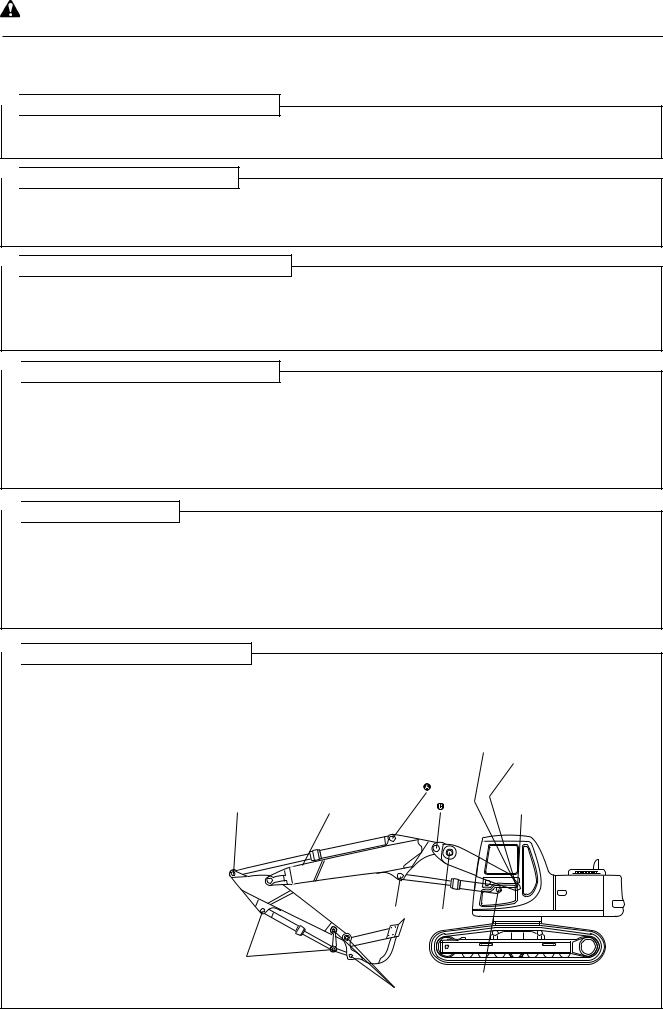
PRECAUTIONS WHEN HANDLING (TWO PIECE BOOM)
When operating the boom arm 2-piece type, select a specialist operator and do not allow any other person to operate the machine.
•Check that the ground inside the operating range is flat and firm.
•Always operate the work equipment slowly.
Especially when lowering the work equipment, move it as slowly as possible to prevent any shock to the machine (operate the work equipment in the same way as when operating a crane).
• Pay attention to warning decal in the cab. (A copy is shown at the bottom of this page)
If the bucket is operated in a certain way, it comes in contact with the machine body (operator’s cab, upper boom, cylinders and undercarriage). When operating the work equipment, take sufficient care not to bring it in contact with the machine body.
Interference
PC290LC/NLC-6K
1-9

|
WARNING: For reasons of safety, al- |
7. PRECAUTIONS DURING OPERATION |
ways follow these safety precautions. |
7.2 OPERATING MACHINE
 WHEN STARTING THE ENGINE
•Walk around for machine again just before mounting it, to check for people and objects that might be in the way.
•NEVER start the engine if a warning tag has been attached to the wrist control.
•When starting the engine, sound the horn as an alert.
•Start and operate the machine only while seated.
•Do not allow anyone other than the operator to ride in the cab or on the machine body.
•For machines equipped with a travel alarm buzzer, check that the warning device operates correctly.
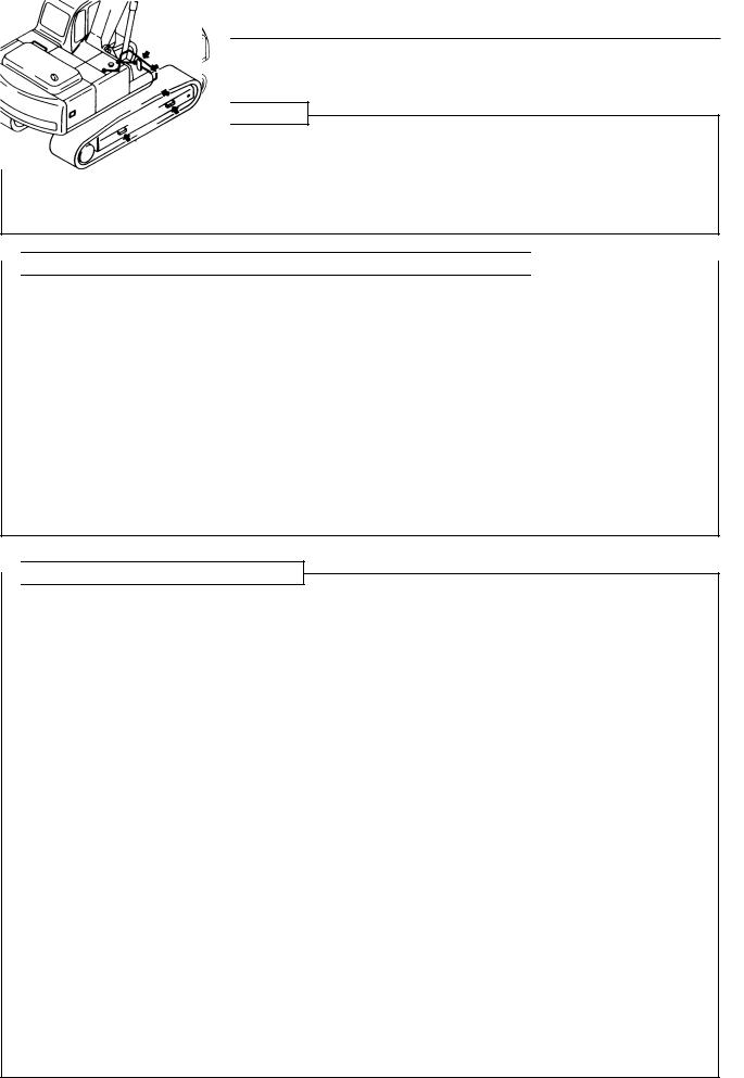
 CHECK DIRECTION BEFORE STARTING MACHINE
Before operating the travel lever, check the direction of the track frame. If the sprocket is at the front, the travel lever must be operated in the opposite direction.
Travel operations n See 12.4 “TO MOVE THE MACHINE OFF.”
Travel in reverse direction
CHECK THAT NO ONE IS IN THE AREA BEFORE SWINGING OR TRAVELLING IN REVERSE
•Always position a signalman in places in dangerous places or places where the view is not clear.
•Make sure that no one comes inside the swing radius or direction of travel.
•Before starting to move, sound the horn or give a signal to warn people not to come close to the machine.
•There are blind spots behind the machine, so if necessary,
swing the upper structure to check that there is no one behind the machine before travelling in reverse.
1-10
PC290-ENG
WARNING: Failure to follow these safety |
|
precautions may lead to a serious accident. |
7. PRECAUTIONS DURING OPERATION |
 PRECAUTIONS WHEN TRAVELLING
•Fold in the work equipment as shown in the diagram below, and keep it at a height of 40-50 cm (16 to 20 in) from the ground level before starting to travel.
•When travelling, do not operate the work equipment control levers. If the work equipment control levers have to be operated, never operate them suddenly.
•When travelling on rough ground, travel at low speed, and avoid sudden changes in direction.
•Avoid travelling over obstacles as far as possible. If the machine has to travel over an obstacle, keep the work equipment as close to the ground as possible and travel at low speed. Never travel over obstacles which make the machine tilt strongly (10o or more).
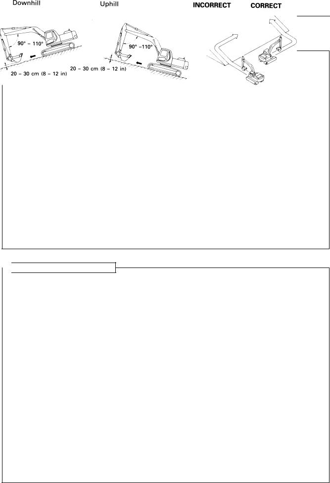
 TRAVELLING ON SLOPES
•Travelling on hills, banks or slopes that are steep could result in the machine tipping over or slipping.
•On hills, banks or slopes, carry the bucket closer to the ground, approximately 20 to 30 cm (8 to 12 in) above the ground. In case of emergency, quickly lower the bucket to the ground to help the machine stop and prevent it from tipping over.
•Do not turn on slopes or travel across slopes. Always go down to a flat place to perform these operations.
Method of travelling on slopes n See 12.12 “PRECAUTIONS WHEN TRAVELLING UP OR
DOWN HILLS.”
•Do not travel up and down on grass, fallen leaves, and wet steel plates. These materials may allow the machine to slip, if it is travelling sideways. Keep travel speed very low.
20 - 30 cm (8 - 12 in)
PC290-ENG
1-11

|
WARNING: For reasons of safety, al- |
|
7. PRECAUTIONS DURING OPERATION |
ways follow these safety precautions. |
|
|
|
|
 PROHIBITED OPERATIONS
•Do not dig the work face under an overhang. This may cause the overhang to collapse and fall on top of the machine.
•Do not carry out deep digging under the front of the machine. The ground under the machine may collapse and cause the machine to fall.
 DO NOT GO CLOSE TO HIGH-VOLTAGE CABLES
•Going close to high-voltage cables can cause electric shock. Always maintain the safe distance given below between the machine and the electric cable.
•The following actions are effective in preventing accidents.
1)Wear shoes with rubber of leather soles.
2)Use a signalman to give warning if the machine approaches too close to the electric cable.
•If the work equipment should touch the electric cable, the operator should not leave the operator’s compartment.
•When carrying out operations near high voltage cables, do not let anyone come close to the machine.
•Check with the electricity company about the voltage of the cables before starting operations.
Voltage |
Min. safety |
||
|
distance |
||
|
|
|
|
6.6 kV |
3 m |
10 ft |
|
|
|
|
|
33.0 kV |
4 m |
14 ft |
|
66.0 kV |
5 m |
17 ft |
|
|
|
|
|
154.0 kV |
8 m |
27 ft |
|
|
|
|
|
275.0 kV |
10 m |
33 ft |
|
|
|
|
|
1-12
PC290-ENG
WARNING: Failure to follow these safety |
|
precautions may lead to a serious accident. |
7. PRECAUTIONS DURING OPERATION |
PC290-ENG
 DO NOT HIT WORK EQUIPMENT
•When working in places where there are height limits, such as in tunnels, under bridges, under electric cables, or in garages, be extremely careful not to hit the boom or arm.
 ENSURE GOOD VISIBILITY
•When working in dark places, install working lamps and head lamps, and set up lighting in the work area if necessary.
•Stop operations if the visibility is poor, such as in mist, snow, or rain, and wait for the weather to improve to a condition that allows the operation to be carried out safely.
 OPERATE CAREFULLY ON SNOW
•When working on snow or icy roads, even a slight slope may cause the machine to slip to the side, so always travel at low speed and avoid sudden starting, stopping, or turning.
•When there has been heavy snow, the road shoulder and objects placed beside the road are buried in the snow and cannot be seen, so always carry out snow-clearing operations carefully.
 WORKING ON LOOSE GROUND
•Avoid operating your machine too close to the edge of cliffs, overhangs, and deep ditches. If these areas collapse, your machine could fall or tip over and result in serious injury or death. Remember that the soil after heavy rain or blasting is weakened in these areas.
•Earth laid on the ground and the soil near ditches are loose. They can collapse under the weight or vibration of your machine.
•Install the HEAD GUARD (FOPS) if working in areas where there is danger of falling rocks and dirt.
 TWO PIECE BOOM
•Positioner cylinder rod and boom rod being extended and bucket being retracted, pay utmost attention to base boom lifting since, after a short run, the bucket reaches the cab area and, consequently, danger of collision becomes possible.
•Do not operate the control levers suddenly.
•Do not start or stop the swing suddenly.
•Do not use the swing force for hitting operations.
 CHECK BEFORE STARTING
Always carry out the following inspection and maintenance before starting work each day. 1. Greasing
•For location of the grease points on first and second booms refer to page 1-6.
•Supply grease to the greasing points shown in the diagram below (total: 16 places).
|
|
|
|
|
Boom cylinders (2 places: for D, E) |
|
|
|
|
|
Positioning cylinder (1 place) |
|
|
|
|
|
|
|
|
A |
|
||
|
|
|
|
|
|
Arm Cylinder (1 place) |
3 places (for A, B, C) |
|
C |
Boom foot (2 places) |
|
B DE
Bucket Cylinder
(2 places)
Boom Cylinder (2 places)
Backhoe bucket and link (3 places)
2. Check for cracks, furrows in the base metal.
1-13
|
WARNING: For reasons of safety, al- |
7. PRECAUTIONS DURING OPERATION |
ways follow these safety precautions. |
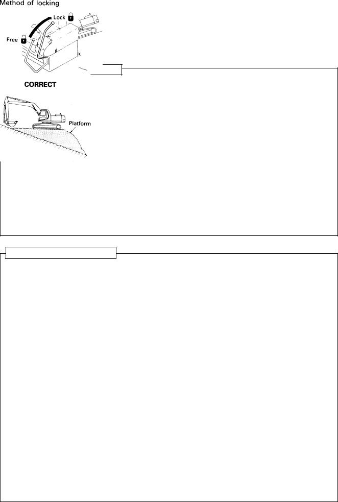
 OPERATIONS ON SLOPES
•When working on slopes, there is danger that the machine may lose its balance and turn over when the swing or work equipment are operated. Always carry out these operations carefully.
•Do not swing the work equipment from the uphill side to the downhill side when the bucket is loaded. This operation is dangerous.
(See the upper diagram on the right.)
•If the machine has to be used on a slope, pile the soil to make a platform that will keep the machine as horizontal as possible. (See the lower diagram on the right.)
Piled soil on slope n See 12.12 “PRECAUTIONS WHEN
TRAVELLING UP OR DOWN HILLS.”
PARKING THE MACHINE
•Park on level ground whenever possible. If not possible, block the tracks, lower the bucket to the ground and thrust the bucket in the ground.
•When parking on public roads, provide fences and signs, such as flags or lights, on the machine to warn passersby to be careful. Be sure that the machine, flags or lights do not obstruct traffic.
Parking procedure n See 12.16 “PARKING THE MACHINE.”
•When leaving the machine, lower the work equipment completely to the ground, set the safety lock lever to the LOCK position, then stop the engine and use the key to lock all the equipment. Always take the key with you.
Work equipment posture n See 12.16 “PARKING THE MACHINE’’. Places to lock n See 12.20 “LOCKING’’.
1-14
PC290-ENG

WARNING: Failure to follow these safety |
|
precautions may lead to a serious accident. |
7. PRECAUTIONS DURING OPERATION |
7.3 TRANSPORTATION
 LOADING AND UNLOADING
•Loading and unloading the machine always involves potential hazards. EXTREME CAUTION SHOULD BE USED.
When loading or unloading the machine, run the engine at low idling and travel at low speed.
•Perform loading and unloading on firm, level ground only. Maintain a safe distance from the edge of a road.
•ALWAYS block the wheels of the hauling vehicle and place blocks under both ramps before loading and unloading.
•ALWAYS use ramps of adequate strength. Be sure the ramps are wide and long enough to provide a safe loading slope.
•Be sure that the ramps are securely positioned and fastened, and that the two sides are at the same level as one another.
•Be sure the ramp surface is clean and free of grease, oil, ice and loose materials. Remove dirt from the machine tracks.
•NEVER correct your steering on the ramps. If necessary, drive away from the ramps and climb again.
•Swing the upper structure with extreme care on the trailer to avoid a possible accident caused by body instability.
•After loading, block the machine tracks and secure the machine with tie-downs.
Loading and unloading |
See n 13 “TRANSPORTATION” |
Tie-downs |
See n 13 “TRANSPORTATION” |
 SHIPPING
•When shipping the machine on a hauling vehicle, obey all state and local laws governing the weight, width, and length of a load. Also obey all applicable traffic regulations.
•Determine the shipping route while taking into account the width, height and weight of the load.
PC290-ENG
1-15

|
WARNING: For reasons of safety, al- |
7. PRECAUTIONS DURING OPERATION |
ways follow these safety precautions. |
7.4 BATTERY
 BATTERY HAZARD PREVENTION
•Battery electrolyte contains sulphuric acid and can quickly burn the skin and eat holes in clothing. If you spill acid on yourself, immediately flush the area with water.
•Battery acid could cause blindness if splashed into the eyes. If acid gets into the eyes, flush them immediately with large quantities of water and see a doctor at once.
•If you accidentally drink acid, drink a large quantity of water or milk, beaten egg or vegetable oil. Call a doctor or poison prevention centre immediately.
•When working with batteries. ALWAYS wear safety glasses or goggles.
•Batteries generate hydrogen gas. Hydrogen gas is very EXPLOSIVE, and is easily ignited with a small spark or flame.
•Before working with batteries, stop the engine and turn the starting switch to the OFF position.
•Avoid short-circuiting the battery terminals through accidental contact with metallic objects, such as tools, across the terminals.
•When removing or installing, check which is the positive (+) terminal and negative (-) terminal.
•Tighten the battery cap securely.
•Tighten the battery terminals securely. Loosened terminals can generate sparks and lead to an explosion.
•When removing battery cap wear rubber groves to prevent electrolyte contact with skin.
 STARTING WITH BOOSTER CABLES
•ALWAYS wear safety glasses or goggles when starting the machine with booster cables.
•When starting from another machine, do not allow the two machines to touch.
•Be sure to connect the positive (+) cable first when installing the booster cables. Disconnect the ground or negative (-) cable first when removing them.
•If any tool touches between the positive (+) terminal and the chassis, it will cause sparks. This is dangerous, so be sure to work carefully.
•Connect the batteries in parallel: positive to positive and negative to negative.
•When connecting the ground cable to the frame of the machine to be started, be sure to connect it as far as possible from the battery.
Starting with booster cables n See 16.5 “IF BATTERY IS DISCHARGED.”
INCORRECT
1-16
PC290-ENG
WARNING: Failure to follow these safety |
|
precautions may lead to a serious accident. |
7. PRECAUTIONS DURING OPERATION |
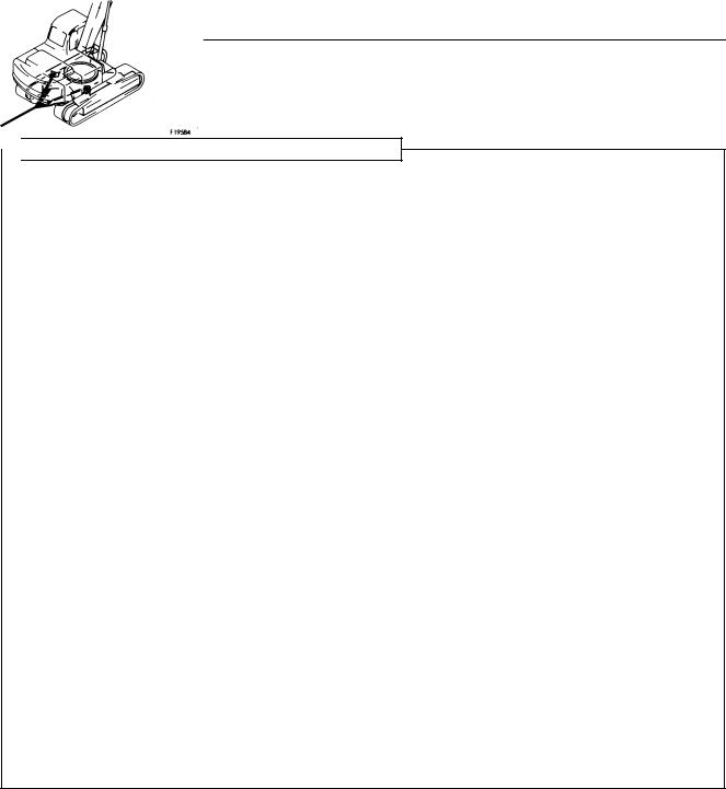
7.5 TOWING
 WHEN TOWING, ATTACH WIRE TO FRAME
•Injury or death could result if a disabled machine is towed incorrectly.
•If you machine is towed by another machine, ALWAYS use a wire rope with a sufficient towing capacity.
•NEVER allow a disabled machine to be towed on a slope.
•Do not use a chinked or frayed wire rope.
•Do not straddle the towing cable or wire rope.
•When connecting up a towing machine, do not let anyone enter the area between the towing machine and the equipment being towed.
•Set the towing machine and the towing connection of the equipment being towed in a straight line when connecting it.
•Place pieces of wood between the wire ropes and body to protect them from wear of damage.
•Never tow the machine using the light-duty towing hole.
Towing method n See 16.2 “METHOD OF TOWING MACHINE.”
CORRECT |
INCORRECT |
PC290-ENG
1-17

|
WARNING: For reasons of safety, al- |
7. PRECAUTIONS DURING OPERATION |
ways follow these safety precautions. |
7.6 BUCKET WITH HOOK
7.6.1 GENERAL PRECAUTIONS
SPECIAL HOOK
• When carrying out lifting work, the special lifting hook is nec- |
GEFAHR |
essary. |
|
• The following operations are prohibited. |
|
° Lifting loads with a wire rope fitted around the bucket teeth. |
|
° Lifting loads with the wire rope wrapped directly around the |
|
boom or arm. |
|
CHECKING HOOK
•When lifting a load, carry out the following checks to confirm that there is no abnormality before starting operations.
°Check that there are no cracks or deformation in the lifting equipment.
°Check that there is no abnormality in the stopper device.
HOOKING WIRE ROPE SECURELY TO HOOK
• When performing lifting operation, securely hook the wire rope onto the special lifting hook.
PRECAUTIONS FOR MACHINE INSTALLATION
•After carrying out a preliminary inspection of ground conditions, select a flat, solid location. Confirm that the machine can be safely operated without toppling or rolling.
PROHIBITED OPERATIONS OTHER THAN MAIN APPLICATIONS
• When performing lifting operation, never raise or lower a person.
NO PERSONS SHALL BE PERMITTED TO ENTER THE WORKING AREA 
•Due to the possible danger of the load falling or of collision with the load, no persons shall be allowed in the working area.
1-18
PC290-ENG
 Loading...