


 Loading...
Operation & Maintenance |
WEAM005900 |
|
|
|
|
Manual |
|
|
|
|
|
|
|
|
|
|
|
|
|
|
|
|
|
|
|
|
WH609-1 WH613-1 WH713-1 WH714-1 WH714H-1 WH716-1
TELESCOPIC HANDLERS
MODEL |
SERIAL NUMBER |
|
WH609-1 |
395F60001 |
and up |
WH613-1 |
395F60003 |
and up |
WH713-1 |
395F70001 |
and up |
WH714-1 |
395F70002 |
and up |
WH714H-1 |
395F70003 |
and up |
WH716-1 |
395F70004 |
and up |

 WARNING
Unsafe use of this machine may cause serious injury or death. Operators and maintenance personnel must read this manual before operating or maintaining this machine.
This manual should be kept inside the cab for reference and periodically reviewed by all personnel who will come into contact with the machine.

FOREWORD
1.1 FOREWORD
•This manual has been developed by Komatsu Utility in order to supply their customers with all the necessary information on the machine and the safety regulations related to it, as well as with the use and maintenance instructions that enable the operator to exploit the capacity of the machine with optimal results and to keep the machine efficient over time.
•The operation manual, together with the spare parts catalogue, is an integral part of the machine and must accompany it, even when it is resold, until its final disposal.
•The manual must be handled with the greatest care and always kept on board, so that it can be consulted at any moment; it must be placed in the appropriate compartment behind the seat, where also the owner’s and registration documents are usually kept.
•This manual must be given to the personnel who have to use the machine and carry out the routine maintenance operations; they must read the contents carefully more than once, in such a way as to clearly understand what are the correct operating conditions and the dangerous conditions that must be avoided.
In case of loss or damage, request a new copy to Komatsu Utility or your Komatsu Utility Dealer.
•The illustrations contained in this manual may represent machine configurations available on request.
The machines are constantly upgraded in order to increase their efficiency and reliability; this manual sums up all the information regarding the state of the art at the moment when the machine is launched on the market. Consult your Komatsu Utility Dealer for any updated information.
•Punctual periodic annotations regarding the maintenance operations that have been carried out are important to have a clear prospect of the situation and to know exactly what has been done and what has to be done after the next maintenance interval.
Therefore, it is advisable to consult either the hour meter and the maintenance plan frequently.
•Over the years Komatsu Utility Dealers have gathered considerable experience in customer service.
If more information is needed, do not hesitate to contact your Komatsu Utility Dealer: he always knows how to get the best performance from the machine, he can suggest the use of the equipment that is most suitable for specific needs and can provide the technical assistance necessary for any change that may be required to conform the machine to the safety standards and traffic rules.
Furthermore, Komatsu Utility Dealers also ensure their assistance for the supply of Komatsu Utility genuine spare parts, which alone guarantee safety and interchangeability.
•The table included in this manual must be filled in with the machine data, which must always be indicated to the Dealer when requiring assistance and ordering spare parts.
 ATTENTION
•Incorrect use and maintenance of the machine may be hazardous and cause serious injury and even death.
•Operators and maintenance personnel must carefully read this manual before using the machine or performing maintenance operations.
•Some actions involved in the operation and maintenance of the machine may cause serious injury or even death, if they are not performed in compliance with the instructions given herein.
•The procedures and precautions described in this manual are valid for application to the machine only when it is used correctly. If the machine is used for any purpose or in any way other than those described herein, the operator shall be responsible for his own safety and for the safety of any other person involved.
1

INFORMATION ON SAFETY
1.2 INFORMATION ON SAFETY
Many accidents are caused by insufficient knowledge of and failure to comply with the safety regulations prescribed for the maintenance operations that must be performed on the machine.
In order to avoid accidents, before starting work and before carrying out any maintenance operation, carefully read and be sure to understand all the information and warnings contained in this manual and given on the plates applied onto the machine.
To identify the messages regarding safety that are included in this manual and written on the machine plates, the following words have been used.
 DANGER
•This word is used in safety messages and on safety labels where there is a high probability of serious injury or death if the hazard is not avoided.
These safety messages or labels usually describe the precautions that must be taken to avoid the hazard.
Failure to take these precautions may also result in serious damage to the machine.
 WARNING
•This word is used in safety messages and on safety labels to signal a potentially dangerous situation which could result in serious injury or even death.
These safety messages or labels usually describe the precautions that must be taken to avoid the hazard.
Failure to take these precautions may also result in serious damage to the machine.
 ATTENTION
•This word is used in safety messages and on safety labels to signal hazards which could result in minor or moderate injury or damage.
This kind of warning is used even to signal hazards which may cause damage only to the machine.
IMPORTANT
•This word is used when precautions are indicated, which must be taken to avoid actions that may shorten the service life of the machine.
NOTE
• This word is used to indicate a useful piece of information.
Komatsu Utility cannot reasonably predict every circumstance that might involve a potential hazard during the operation or maintenance of the machine; for this reason, the safety messages included in this manual and applied onto the machine may not include all possible safety precautions.
If all the procedures and operations prescribed for this machine are kept to, you can be sure that the operator and the persons in the vicinity will work in total safety, with no risk of damaging the machine.
In case of doubt regarding the safety measures necessary for some procedures, contact Komatsu Utility or your local Dealer.
2

INFORMATION ON SAFETY
 DANGER
•Before starting any maintenance operation, position the machine on a firm and level surface, engage the safety locks of the equipment and the controls, stop the engine and apply the parking brake.
•For the sake of clarity, some illustrations contained in this manual may represent the machine without guards.
Do not use the machine without guards and do not start the engine when the engine hood is open, unless this is expressly required for some maintenance operations.
•It is strictly forbidden to modify the setting of the hydraulic system safety valves; Komatsu cannot be held liable for any damage to persons, property, or the machine, if the machine has been tampered with by modifying the standard setting of the hydraulic system.
•Before carrying out any electrical welding, disconnect the battery, the alternator and the connector of the gearshift unit installed under the steering wheel.
(See «2.8.12 PRECAUTIONS CONCERNING THE BATTERY AND THE ALTERNATOR» and «2.8.14 PRECAUTIONS CONCERNING THE GEAR LEVER»).
•Install only authorized additional equipment.
•The machine can travel on roads only if fitted with homologated equipment; before travelling on roads, make sure that the equipment fitted is homologated and that the safety locks provided are correctly engaged.
•Incorrect use of this machine may cause serious injury or death.
Operators and maintenance personnel must read this manual before operating or servicing the machine. This manual must be kept inside the cab for reference and periodically reviewed by the personnel using the machine.
3

INTRODUCTION
1.3 INTRODUCTION
1.3.1 INTENDED USES
The Komatsu Utility TELESCOPIC HANDLERS described in this manual are suitable for operation at temperatures ranging from –16°C to +45°C and for use by operators skilled mainly in the following types of work:
• Lifting and handling of palletized or free loads on even or uneven ground.
NOTE
• Free loads and loads with particular shapes must be secured to the forks or to the lifting equipment.
Through the application of approved optional attachments, the machine can also be used for:
•loading work
•handling loose material (cereals, sand, gravel, etc.) with STANDARD BUCKET or 4 IN 1 BUCKET.
•handling piles, trees, etc. with specific forks.
1.3.2 IMPROPER OR UNAUTHORIZED USE
 ATTENTION
•This paragraph describes some of the improper or unauthorized uses of the machine; since it is impossible to predict all the possible improper uses, if the machine happens to be used for particular applications, contact your Komatsu Utility Dealer before carrying out the work.
IMPORTANT
•The instructions regarding the authorized optional equipment are given in the relevant operation and maintenance manuals; if the equipment is supplied by Komatsu Utility, these publications are enclosed to this manual.
•The instructions regarding the assembly of the authorized equipment, the controls requiring special machine configurations and the hydraulic couplings necessary for the operation of the equipment are grouped in the final section of this manual.
The Komatsu Utility TELESCOPIC HANDLERS are designed and built exclusively for handling and transporting inert materials; the following applications are forbidden:
•Use of the machine at temperatures different from those indicated.
•Use of the machine by minors or unexperienced persons.
•Use of the machine by persons under the effect of alcohol, medicines that may affect attention levels, drugs.
•Use of the machine to lift persons or with forks, or pallets or equipment not approved from Komatsu Utility for this specific type of application.
•Use the machine for lifting operations in combination with other machines.
•Transport of people, even if they are in the operator’s cab.
•Transport and lifting of containers containing flammable fluids or fluids that can be considered dangerous without using the apposite retaining equipment (harness).
•Transport and lifting (even if in exceptional cases) of equipment or loose materials that protrude from the forks and are not secured with cables or chains.
•Use of the bucket to drive or extract piles.
•Use of the machine to tow damaged or failed vehicles.
•Use of the machine to lift damaged or failed vehicles.
4
INTRODUCTION
1.3.3 MAIN CHARACTERISTICS
•Simple and easy to use.
•Cab (ROPS/FOPS level 2).
•Servo steering through hydraulic system with priority to steering needs. Three steering modes selected with push buttons:
-Two-wheel steering (compulsory for travelling on roads)
-Four-wheel steering (round steering)
-Crab steering
•Selection of the machine operating mode (travel – travel + work - work).
•Gearshift with electronic selection of gears through solenoid actuators and transmission with hydraulic converter; reversal and speed change with controls on a single lever.
•Boom lifting and equipment swinging control with servo lever that makes it possible to modulate the movements in a proportional and continuous way.
•Boom extension with potentiometer acting on a proportional solenoid valve.
•Safety valves for each movement of the cylinders.
•Controls and instrumentation visible form the work position.
•Accelerator pedal.
•Service brakes with foot control acting on the two axles.
•Simplified maintenance with reduced intervals.
•Independent controls for the stabilizers (optional).
•Frame levelling controlled through a water level (spirit level) and a rocker switch control with automatic return to the central position (optional).
•SLI-Safe Load Indicator.
•Axle-frame lock that engages automatically when the boom inclination exceeds approximately 30° (optional).
1.3.4 RUNNING-IN
Every machine is scrupulously adjusted and tested before delivery.
A new machine, however, must be used carefully for the first 100 hours, in order to ensure proper running-in of the various components.
Every new machine must be used carefully, paying special attention to the following indications:
•After the start, let the engine idle for 5 minutes, in such a way as to warm it up gradually before actual operation.
•When warming the engine up, carry out some lifting cycles with an average load and extend the boom a few times, so that the hydraulic oil warms up more easily.
•Cover short distances at low speed to warm up the axles and transmission oil.
•Avoid operating the machine reaching the load limits allowed or at high speed.
•Avoid abrupt starts or accelerations, useless sudden decelerations and abrupt reversals, especially when travelling at the maximum speed allowed for each gear.
•After the first 250 hours of operation, besides the maintenance operations to be performed every 250 hours of operation, it is also necessary to:
1 - Change the transmission filter.
2 - Change the oil in the differential unit (front and rear axle).
3 - Change the oil in the final reduction gears (front and rear axle). 4 - Change the hydraulic circuit oil drain filter.
5

INTRODUCTION
SYNTHETIC BIODEGRADABLE OIL TYPE HEES
On machines in which the synthetic biodegradable oil type HEES is used, the following operations are to be performed together with the standard maintenance operations:
•After the first 250 hours of operation, change the hydraulic circuit drain filter.
•After the first 500 hours of operation, change the hydraulic circuit oil and the intake filter.
IMPORTANT
•When changing the oil filters (cartridges), check their innner part to make sure that there are no deposits.
If abundant deposits are observed, find out what may have caused their accumulation before starting the machine.
•The number of operating hours is indicated by the hour meter.
6
PRODUCT IDENTIFICATION
1.4 PRODUCT IDENTIFICATION
The Komatsu Utility TELESCOPIC HANDLERS and their main components are identified by serial numbers stamped on the identification plates.
The serial number and the identification numbers of the components are the only numbers that must be indicated to the Dealer when requiring assistance and ordering spare parts.
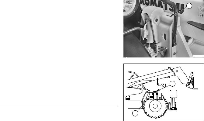
1.4.1MACHINE IDENTIFICATION PLATE AND PRODUCT IDENTIFICATION NUMBER (PIN)
The machine bears the data required by the EC Directives, as well as the Product Identification Number (PIN) (1).
The PIN is:
a - stamped on the front right part of the machine.
b - indicated on the identification plate as alphanumeric stamping and as a bar code.
The identification plate (2) is fixed to the front right part of the frame, in a protected place, in such a way as to prevent it from getting damaged and becoming illegible.
NOTE
•If the serial number on the plate has been damaged, it can be obtained by separating the last 6 digits of the PIN.
1 |
RKAA0880 |
1 |
2 |
RKA01690 |
7

PRODUCT IDENTIFICATION
1.4.2 MACHINE IDENTIFICATION PLATE
TYPE |
|
SERIAL No. |
|
MANUFACTURING YEAR |
|
MASS |
kg |
RATED CAPACITY |
kg |
ENGINE POWER |
kW |
Product Identification Number |
|
PIN |
|
MANUFACTURED BY KOMATSU UTILITY EUROPE S.p.A. |
|
36025 NOVENTA VICENTINA (VI) - ITALY - |
395-93-11570 |
|
RKA02031 |
8
PRODUCT IDENTIFICATION
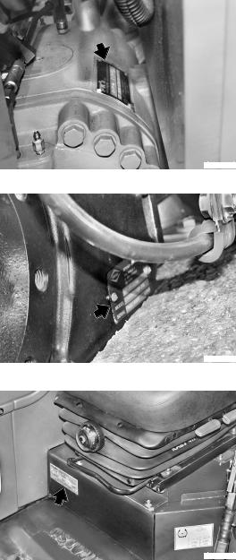
1.4.3 ENGINE SERIAL NUMBER AND EXHAUST GAS EMISSION PLATE
The identification plate (1) is fixed to the timing case and indicates the engine model, total displacement and serial number.
In addition to the Manufacturer’s trademark, the identification plate (2) also indicates the following:
1 |
- Engine type |
1 |
|
||
2 |
- Engine Family |
|
3 |
- Serial no. |
|
4 |
- EC Type Approval |
|
RKAA0420
The serial number (3) is also stamped on the right side of the cylinder block, on the upper part of the oil cooling heat exchanger.
The engine class plate |
(4) and the engine details (EPA Family, |
2 |
engine model, engine |
displacement, engine power/RPM, idle |
speed, quantity of fuel/cycle, valve clearance and U.S.EPA CARB conformity) can be found on the plate positioned below the Manufacturer’s plate.
Both plates (2) and (4) are applied to the left side of the timing case.
RKAA0410
 3
3
RKAA0430
1.4.4 FRONT AXLE SERIAL NUMBER
The front axle serial number is stamped on the plate positioned on the central body.
RKAA0440
9
PRODUCT IDENTIFICATION
1.4.5 REAR AXLE SERIAL NUMBER
The rear axle serial number is stamped on the plate positioned on the central body.
RKAA0450
1.4.6 TRANSMISSION SERIAL NUMBER
The transmission serial number is stamped on the plate positioned on the transmission case, on the engine coupling side.
RKAA0460
1.4.7 CAB SERIAL NUMBER
The cab serial number is stamped on the plate positioned on the front right base crosspiece.
RKAA0470
10

PRODUCT IDENTIFICATION
1.4.8 SERIAL NUMBERS AND DEALER’S ADDRESS
Machine No. |
|
|
|
|
|
|
Model |
|
|
||
Product identification number (PIN) |
|
|
|
|
|||||||
Engine No. |
|
|
|
|
|
|
|
|
|
|
|
Front axle No. |
|
|
|
|
|
|
|
||||
Rear axle No. |
|
|
|
|
|
|
|||||
Transmission No. |
|
|
|
|
|
|
|||||
Cab No. |
|
|
|
|
|
|
|
||||
Optional equipment: |
|
|
|
|
|
||||||
|
|
|
|
|
|
|
|
|
|
|
|
|
|
|
|
|
|
|
|
|
|
|
|
Dealer:
Address:
Tel.
Contact person:
NOTES:
11
TABLE OF CONTENTS
TABLE OF CONTENTS
FOREWORD
1.1 |
FOREWORD.......................................................................................................................................... |
1 |
|
1.2 |
INFORMATION ON SAFETY ................................................................................................................ |
2 |
|
1.3 |
INTRODUCTION ................................................................................................................................... |
4 |
|
|
1.3.1 |
INTENDED USES..................................................................................................................... |
4 |
|
1.3.2 IMPROPER OR UNAUTHORIZED USE .................................................................................. |
4 |
|
|
1.3.3 |
MAIN CHARACTERISTICS...................................................................................................... |
5 |
|
1.3.4 |
RUNNING-IN ............................................................................................................................ |
5 |
1.4 |
PRODUCT IDENTIFICATION ............................................................................................................... |
7 |
|
|
1.4.1 MACHINE IDENTIFICATION PLATE AND PRODUCT IDENTIFICATION NUMBER (PIN) .... |
7 |
|
|
1.4.2 |
MACHINE IDENTIFICATION PLATE ....................................................................................... |
8 |
|
1.4.3 ENGINE SERIAL NUMBER AND EXHAUST GAS EMISSION PLATE ................................... |
9 |
|
|
1.4.4 FRONT AXLE SERIAL NUMBER............................................................................................. |
9 |
|
|
1.4.5 REAR AXLE SERIAL NUMBER ............................................................................................... |
10 |
|
|
1.4.6 |
TRANSMISSION SERIAL NUMBER ........................................................................................ |
10 |
|
1.4.7 |
CAB SERIAL NUMBER ............................................................................................................ |
10 |
|
1.4.8 SERIAL NUMBERS AND DEALER’S ADDRESS .................................................................... |
11 |
|
|
TABLE OF CONTENTS ........................................................................................................................ |
12 |
|
SAFETY DEVICES AND ACCIDENT-PREVENTION MEASURES
2.1 SAFETY, NOISE AND VIBRATION PLATES....................................................................................... |
20 |
|
2.1.1 POSITION OF THE SAFETY PLATES..................................................................................... |
20 |
|
2.1.2 |
PICTOGRAMS AND RELEVANT MEANINGS......................................................................... |
24 |
2.1.3 |
POSITION OF THE NOISE PLATES ...................................................................................... |
32 |
2.2 GENERAL PRECAUTIONS .................................................................................................................. |
33 |
|
2.2.1 |
GENERAL SAFETY RULES..................................................................................................... |
33 |
2.2.2 |
SAFETY DEVICES AND GUARDS .......................................................................................... |
33 |
2.2.3 |
CLOTHING AND PERSONAL PROTECTION ITEMS ............................................................. |
33 |
2.2.4 |
UNAUTHORIZED MODIFICATIONS........................................................................................ |
34 |
2.2.5 |
LEAVING THE OPERATOR’S SEAT ....................................................................................... |
34 |
2.2.6 |
GETTING ON AND OFF THE MACHINE................................................................................. |
35 |
2.2.7 |
CHECKING THE REAR-VIEW MIRRORS ............................................................................... |
35 |
2.2.8 |
PREVENTING FIRES DUE TO FUEL AND OIL....................................................................... |
36 |
2.2.9 |
PREVENTING BURNS............................................................................................................. |
36 |
2.2.10 |
PREVENTING DAMAGE DUE TO ASBESTOS POWDER...................................................... |
37 |
2.2.11 |
PREVENTING DAMAGE CAUSED BY THE WORK EQUIPMENT ......................................... |
37 |
2.2.12 |
FIRE EXTINGUISHERS AND FIRST AID KIT.......................................................................... |
38 |
2.2.13 |
PRECAUTIONS CONCERNING THE CAB STRUCTURE ...................................................... |
38 |
2.2.14 |
PRECAUTIONS CONCERNING THE EQUIPMENT................................................................ |
38 |
2.3 PRECAUTIONS TO BE TAKEN BEFORE STARTING WORK............................................................ |
39 |
|
2.3.1 SAFETY ON THE WORKSITE ................................................................................................. |
39 |
|
2.3.2 |
FIRE PREVENTION ................................................................................................................. |
39 |
2.3.3 |
PRECAUTIONS CONCERNING THE DRIVING POSITION.................................................... |
39 |
12
|
|
TABLE OF CONTENTS |
2.3.4 |
ROOM VENTILATION.............................................................................................................. |
40 |
2.3.5 |
PRECAUTIONS CONCERNING THE LIGHTS........................................................................ |
40 |
2.3.6CLEANING THE WINDOWS AND THE REAR-VIEW MIRRORS-
|
CHECKING THE WINDSHIELD WIPER BLADES ................................................................... |
40 |
|
2.4 PRECAUTIONS TO BE TAKEN DURING WORK................................................................................ |
41 |
||
2.4.1 |
WHEN STARTING THE ENGINE ............................................................................................ |
41 |
|
2.4.2 |
RULES FOR TRAVELLING ON ROADS ................................................................................. |
41 |
|
2.4.3 |
CHECKS FOR TRAVELLING IN REVERSE............................................................................ |
42 |
|
2.4.4 |
MOVING THE MACHINE ......................................................................................................... |
42 |
|
2.4.5 |
MOVING ON SLOPES ............................................................................................................ |
43 |
|
2.4.6 |
WORKING ON SLOPES .......................................................................................................... |
44 |
|
2.4.7 |
UNAUTHORIZED OPERATIONS ............................................................................................ |
44 |
|
2.4.8 |
WORKING IN WINDY WEATHER CONDITIONS.................................................................... |
45 |
|
2.4.9 |
MAIN OPERATING MODES .................................................................................................... |
46 |
|
|
2.4.9.1 |
LOADING THE MATERIAL ..................................................................................... |
46 |
|
2.4.9.2 |
UNLOADING THE MATERIAL................................................................................ |
48 |
2.4.10 |
PREVENTING ELECTROCUTION .......................................................................................... |
50 |
|
2.4.11 |
VISIBILITY................................................................................................................................ |
50 |
|
2.4.12 |
WORKING ON ICY OR SNOW-COVERED SURFACES ........................................................ |
50 |
|
2.4.13 |
PREVENTING DAMAGE CAUSED BY THE WORK EQUIPMENT ......................................... |
51 |
|
2.4.14 |
WORKING ON LOOSE GROUND ........................................................................................... |
51 |
|
2.4.15 |
PARKING THE MACHINE ....................................................................................................... |
52 |
|
2.5 TRANSPORTING THE MACHINE ON OTHER VEHICLES ................................................................. |
53 |
||
2.5.1 |
LOADING AND UNLOADING THE MACHINE......................................................................... |
53 |
|
2.5.2 |
THE ROUTE............................................................................................................................. |
53 |
|
2.6 BATTERY.............................................................................................................................................. |
|
54 |
|
2.6.1 |
SAFETY PRECAUTIONS FOR WORK ON BATTERIES ........................................................ |
54 |
|
2.6.2 |
STARTING WITH BOOSTER CABLES ................................................................................... |
54 |
|
2.7 PRECAUTIONS FOR EMERGENCY RECOVERY............................................................................... |
55 |
||
2.8 PRECAUTIONS TO BE TAKEN DURING MAINTENANCE................................................................. |
56 |
||
2.8.1 |
WARNING PLATES ................................................................................................................ |
56 |
|
2.8.2 |
TOOLS .................................................................................................................................... |
|
56 |
2.8.3 |
PERSONNEL ........................................................................................................................... |
56 |
|
2.8.4 |
EQUIPMENT ............................................................................................................................ |
57 |
|
2.8.5 |
WORKING UNDER THE MACHINE ........................................................................................ |
57 |
|
2.8.6 |
KEEPING THE MACHINE CLEAN........................................................................................... |
57 |
|
2.8.7 |
USE OF THE ENGINE DURING MAINTENANCE ................................................................... |
58 |
|
2.8.8 |
PERIODICAL CHANGE OF THE PARTS THAT ARE CRITICAL FOR SAFETY..................... |
58 |
|
2.8.9 |
RULES TO BE FOLLOWED WHEN REFUELLING OR ADDING OIL ..................................... |
58 |
|
2.8.10 |
CHECKING THE COOLANT LEVEL IN THE RADIATOR ....................................................... |
59 |
|
2.8.11 |
USING LAMPS ......................................................................................................................... |
59 |
|
2.8.12 |
PRECAUTIONS CONCERNING THE BATTERY AND THE ALTERNATOR .......................... |
59 |
|
2.8.13 |
PRECAUTIONS CONCERNING THE STARTER .................................................................... |
60 |
|
2.8.14 |
PRECAUTIONS CONCERNING THE GEAR LEVER .............................................................. |
60 |
|
2.8.15 |
PRECAUTIONS CONCERNING HIGH-PRESSURE HOSES AND FUEL PIPES ................... |
61 |
|
2.8.16 |
PRECAUTIONS TO BE TAKEN WHEN WORKING ON HIGHPRESSURE SYSTEMS........ |
61 |
|
2.8.17 |
PRECAUTIONS FOR MAINTENANCE WORK INVOLVING HIGH TEMPERATURES AND |
|
|
|
PRESSURES ........................................................................................................................... |
61 |
|
2.8.18 |
COOLING FAN AND FAN BELT .............................................................................................. |
62 |
|
2.8.19 |
WASTE MATERIALS ............................................................................................................... |
62 |
|
13
|
|
|
TABLE OF CONTENTS |
|
|
2.8.20 |
PRECAUTIONS CONCERNING TECHNOPOLYMERS AND ELASTOMERS........................ |
62 |
|
|
2.8.21 |
PRECAUTIONS TO BE TAKEN WHEN INFLATING TYRES .................................................. |
63 |
|
|
2.8.22 |
PRECAUTIONS TO BE TAKEN WHEN USING |
|
|
|
|
SYNTHETIC BIODEGRADABLE OIL TYPE «HEES».............................................................. |
63 |
|
DESCRIPTION AND OPERATION OF THE MACHINE |
|
|||
3.1 |
GENERAL VIEWS |
................................................................................................................................. |
66 |
|
|
3.1.1 |
RIGHT SIDE ...................................................................................................................VIEW |
66 |
|
|
3.1.2 |
LEFT SIDE .....................................................................................................................VIEW |
66 |
|
|
3.1.3 |
CAB INSIDE .................................................................................................GENERAL VIEW |
67 |
|
3.2 |
INSTRUMENTS AND .......................................................................................................CONTROLS |
68 |
||
|
3.2.1 |
INSTRUMENTS........................................................................................................................ |
68 |
|
|
3.2.2 |
WARNING ..................................................................................................................LIGHTS |
70 |
|
|
3.2.3 |
SWITCHES .........................................................................................AND PUSH BUTTONS |
75 |
|
|
3.2.4 |
ELECTRIC .....................................................................................................ACCESSORIES |
82 |
|
|
3.2.5 |
MACHINE ............................................................................................................CONTROLS |
83 |
|
3.3 |
LIFTING LOADS ................................................................................................................................... |
|
105 |
|
|
3.3.1 |
READING ...............................................................................................THE LOAD CHARTS |
105 |
|
|
|
3.3.1.1 ...............................................................DESCRIPTION OF THE LOAD CHARTS |
105 |
|
|
|
3.3.1.2 ............................................................................................. |
USING THE CHARTS |
107 |
3.4 |
FUSES AND RELAYS........................................................................................................................... |
112 |
||
|
3.4.1 |
CENTRAL ...................................................................................UNIT FUSES AND RELAYS |
112 |
|
|
|
3.4.1.1 ......................................................................................... |
CENTRAL UNIT FUSES |
113 |
|
|
3.4.1.2 ....................................................................................... |
CENTRAL UNIT RELAYS |
115 |
|
3.4.2 |
ENGINE LINE ......................................................................................FUSES AND RELAYS |
116 |
|
|
|
3.4.2.1 ............................................................................................ |
ENGINE LINE FUSES |
116 |
|
|
3.4.2.2 .......................................................................................... |
ENGINE LINE RELAYS |
117 |
3.5 GUARDS, CAB AND ................................................................................................DRIVER’S SEAT |
118 |
|||
|
3.5.1 |
ENGINE HOOD ........................................................................................................................ |
118 |
|
|
3.5.2 |
CAB .......................................................................................................................................... |
|
119 |
|
3.5.3 |
EMERGENCY ..................................................................................................................EXIT |
120 |
|
|
3.5.4 |
VENTILATION .................................................................................................AND HEATING |
121 |
|
|
3.5.5 |
AIR CONDITIONER ..................................................................................................(optional) |
123 |
|
|
3.5.6 |
SEAT ........................................................................................................................................ |
|
124 |
|
|
3.5.6.1 .................................................................................................. |
STANDARD SEAT |
124 |
|
|
3.5.6.2 .................................................................................................... |
OPTIONAL SEAT |
125 |
|
3.5.7 |
STEERING ..................................................................................................................WHEEL |
126 |
|
|
3.5.8 |
SAFETY BELT.......................................................................................................................... |
126 |
|
|
3.5.9 |
WINDOW SHADE..................................................................................................................... |
127 |
|
|
3.5.10 |
TECHNICAL .............................................................................................DOCUMENTATION |
127 |
|
|
3.5.11 |
FIRE EXTINGUISHER.............................................................................................................. |
128 |
|
3.6 USE OF THE MACHINE........................................................................................................................ |
129 |
|||
|
3.6.1 |
CHECKS TO ...................................BE CARRIED OUT BEFORE STARTING THE ENGINE |
129 |
|
|
|
3.6.1.1 .................................................................................................... |
VISUAL CHECKS |
129 |
|
|
3.6.1.2 ...................................................................................................... |
DAILY CHECKS |
129 |
|
|
3.6.1.3 ....................................................................................... |
OPERATIONAL CHECKS |
130 |
|
3.6.2 |
STARTING .........................................................................................................THE ENGINE |
131 |
|
|
|
3.6.2.1 ....................STARTING WITH WARM ENGINE OR IN TEMPERATE CLIMATES |
131 |
|
|
|
3.6.2.2 .................................STARTING WITH COLD ENGINE OR IN COLD CLIMATES |
132 |
|
|
3.6.3 |
WARMING .........................................................................................................THE ENGINE |
133 |
|
14
|
|
|
TABLE OF CONTENTS |
|
|
3.6.4 |
HEATING THE HYDRAULIC OIL ............................................................................................. |
133 |
|
|
3.6.5 |
HOW TO MOVE THE MACHINE ............................................................................................. |
134 |
|
|
|
3.6.5.1 |
MOVING ON SLOPES ............................................................................................ |
135 |
|
|
3.6.5.2 |
MAXIMUM IMMERSION DEPTH ............................................................................ |
136 |
3.7 |
PARKING THE MACHINE .................................................................................................................... |
137 |
||
|
3.7.1 |
PARKING ON LEVEL GROUND.............................................................................................. |
137 |
|
|
3.7.2 |
PARKING ON SLOPES............................................................................................................ |
138 |
|
3.8 |
STOPPING THE ENGINE ..................................................................................................................... |
139 |
||
3.9 |
TRANSPORTING THE MACHINE ON OTHER VEHICLES ................................................................. |
140 |
||
|
3.9.1 |
LOADING AND UNLOADING THE MACHINE......................................................................... |
140 |
|
|
3.9.2 |
TRANSPORT ........................................................................................................................... |
141 |
|
|
3.9.3 |
LIFTING THE MACHINE .......................................................................................................... |
141 |
|
3.10 |
PRECAUTIONS TO BE TAKEN IN THE COLD SEASON AND IN COLD PLACES ........................... |
142 |
||
|
3.10.1 |
FUEL AND LUBRICANTS ........................................................................................................ |
142 |
|
|
3.10.2 |
ENGINE COOLANT ................................................................................................................. |
142 |
|
|
3.10.3 |
BATTERY |
................................................................................................................................. |
142 |
|
3.10.4 |
OTHER PRECAUTIONS .......................................................................................................... |
143 |
|
|
3.10.5 |
PRECAUTIONS ......................................................TO BE TAKEN AT THE END OF WORK |
143 |
|
3.11 |
PRECAUTIONS TO ..................................................................BE TAKEN IN THE WARM SEASON |
144 |
||
3.12 |
EQUIPMENT.......................................................................................................................................... |
|
145 |
|
|
3.12.1 |
INSTALLING ......................................EQUIPMENT WITH HYDRAULIC QUICK COUPLING |
145 |
|
|
3.12.2 |
INSTALLING ........................................................EQUIPMENT WITH MANUAL COUPLING |
147 |
|
|
3.12.3 |
INSTALLING EQUIPMENT REQUIRING HYDRAULIC POWER |
|
|
|
|
(4X1 BUCKET ................................................- FORKS – ROUND BALE GRIPPERS, ETC.) |
147 |
|
|
3.12.4 |
ORGANIZING ............................................................................................THE WORK AREA |
148 |
|
|
3.12.5 |
OPERATING ..............................................................................................THE EQUIPMENT |
148 |
|
|
3.12.6 |
OPERATING .............................................................THE MACHINE FITTED WITH FORKS |
149 |
|
|
|
3.12.6.1 .................................................................................................. |
FORKING A LOAD |
149 |
|
|
3.12.6.2 ................................................................................. |
TRANSPORTING THE LOAD |
151 |
|
|
3.12.6.3 ........................................................................................... |
STACKING THE LOAD |
151 |
|
3.12.7 |
PREPARING ..............................................THE MACHINE FOR TRAVELLING ON ROADS |
153 |
|
|
3.12.8 |
USING THE ...................................................................................MACHINE AS A LOADER |
154 |
|
|
|
3.12.8.1 ..........................................................................ORGANIZING THE WORK AREA |
154 |
|
|
|
3.12.8.2 .........................................................LOADING HEAPED AND LEVEL MATERIAL |
154 |
|
3.13 |
LONG PERIODS OF ........................................................................................................INACTIVITY |
156 |
||
|
3.13.1 |
PREPARING ..................................THE MACHINE FOR A LONG PERIOD OF INACTIVITY |
156 |
|
|
3.13.2 |
PREPARING .....................................THE ENGINE FOR A LONG PERIOD OF INACTIVITY |
157 |
|
|
3.13.3 |
MAINTENANCE ...........................................................DURING A PERIOD OF INACTIVITY |
157 |
|
|
3.13.4 |
RESTARTING ...................................................................................................THE ENGINE |
158 |
|
|
3.13.5 |
AFTER A LONG ..............................................................................PERIOD OF INACTIVITY |
158 |
|
3.14 |
OPERATIONS IN CASE .................................................................................................OF FAILURE |
159 |
||
|
3.14.1 |
IF THE ENGINE ..........BREAKS DOWN WITH BOOM LOADED, LIFTED AND EXTENDED |
159 |
|
|
3.14.2 |
REMOVING ...............................................................THE MACHINE IN CASE OF FAILURE |
160 |
|
|
3.14.3 |
IF THE FUEL ..................................................................................................HAS RUN OUT |
160 |
|
|
3.14.4 |
IF THE ENGINE ................FAILS TO START BECAUSE THE BATTERY HAS RUN DOWN |
161 |
|
|
|
3.14.4.1 ..................................................................STARTING WITH BOOSTER CABLES |
162 |
|
|
3.14.5 |
OTHER TROUBLES................................................................................................................. |
163 |
|
|
|
3.14.5.1 ............................................................................................... |
ELECTRIC CIRCUIT |
163 |
|
|
3.14.5.2 ............................................................................................ |
HYDRAULIC SYSTEM |
163 |
15
|
|
|
TABLE OF CONTENTS |
|
|
|
3.14.5.3 |
BRAKING SYSTEM ................................................................................................ |
164 |
|
|
3.14.5.4 |
CONVERTER.......................................................................................................... |
164 |
|
|
3.14.5.5 |
ENGINE................................................................................................................... |
165 |
MAINTENANCE |
|
|
||
4.1 |
GUIDE TO MAINTENANCE .................................................................................................................. |
168 |
||
4.2 |
MAINTENANCE NOTES ....................................................................................................................... |
170 |
||
|
4.2.1 |
NOTES REGARDING THE ENGINE........................................................................................ |
170 |
|
|
|
4.2.1.1 |
ENGINE OIL............................................................................................................ |
170 |
|
|
4.2.1.2 |
COOLANT ............................................................................................................... |
170 |
|
|
4.2.1.3 |
FUEL ....................................................................................................................... |
171 |
|
4.2.2 |
NOTES REGARDING THE HYDRAULIC SYSTEM................................................................. |
171 |
|
|
4.2.3 |
NOTES REGARDING THE ELECTRIC SYSTEM.................................................................... |
172 |
|
|
4.2.4 |
NOTES REGARDING LUBRICATION ..................................................................................... |
172 |
|
|
4.2.5 |
PARTS SUBJECT TO WEAR THAT PERIODICALLY NEED CHANGING.............................. |
173 |
|
4.3 FUEL, COOLANT AND LUBRICANTS................................................................................................. |
174 |
|||
|
4.3 |
LUBRICATION WITH GREASE ............................................................................................... |
174 |
|
|
4.3.1 |
HOMOLOGATED SYNTHETIC BIODEGRADABLE LUBRICANTS “HEES” ........................... |
176 |
|
4.4 DRIVING TORQUES FOR SCREWS AND NUTS ................................................................................ |
177 |
|||
|
4.4.1 |
STANDARD DRIVING TORQUES ........................................................................................... |
177 |
|
|
4.4.2 |
SPECIFIC DRIVING TORQUES .............................................................................................. |
177 |
|
4.5 |
LUBRICATION ...................................................................................................................................... |
|
178 |
|
|
4.5.1 |
LUBRICATION DIAGRAM (2-SECTION BOOM) ..................................................................... |
178 |
|
|
4.5.2 |
LUBRICATION DIAGRAM (3-SECTION BOOM) ..................................................................... |
179 |
|
4.6 PERIODICAL CHANGE OF THE SAFETY-RELATED COMPONENTS.............................................. |
180 |
|||
|
4.6.1 |
CRITICAL PARTS FOR SAFETY............................................................................................. |
181 |
|
|
|
4.6.1.1 |
FUEL SUPPLY SYSTEM ........................................................................................ |
181 |
|
|
4.6.1.2 |
DELIVERY HYDRAULIC SYSTEM ......................................................................... |
182 |
|
|
4.6.1.3 |
CONTROL VALVE HYDRAULIC SYSTEM............................................................. |
183 |
|
|
4.6.1.4 |
BOOM HYDRAULIC SYSTEM................................................................................ |
184 |
4.7 |
MAINTENANCE PLAN.......................................................................................................................... |
185 |
||
|
4.7.1 |
WHEN REQUIRED................................................................................................................... |
189 |
|
|
|
4.7.1.a |
CHECKING THE BATTERY ELECTROLYTE LEVEL – |
|
|
|
|
INSPECTING TERMINALS AND CABLES ............................................................. |
189 |
|
|
4.7.1.b |
CHECKING, CLEANING OR CHANGING THE ENGINE AIR CLEANERS............ |
190 |
|
|
4.7.1.c |
CHECKING AND CLEANING THE CAB AIR FILTER ............................................ |
192 |
|
|
4.7.1.d |
FUSES AND RELAYS – CHECK AND CHANGE ................................................... |
193 |
|
|
4.7.1.e |
CHECKING THE WINDSHIELD WASHER FLUID LEVEL ..................................... |
193 |
|
|
4.7.1.f |
CHECKING THE WINDSHIELD WIPER BLADES.................................................. |
194 |
|
|
4.7.1.g |
LUBRICATING THE CAB DOOR AND ENGINE HOOD HINGES.......................... |
194 |
|
|
4.7.1.h |
LUBRICATING THE FORK SUPPORT ROD.......................................................... |
194 |
|
|
4.7.1.i |
CHECKING THE FUEL LEVEL............................................................................... |
194 |
|
|
4.7.1.j |
TOPPING UP THE BRAKING SYSTEM OIL RESERVOIR .................................... |
195 |
|
4.7.2 |
MAINTENANCE EVERY 10 HOURS OF OPERATION OR EVERY DAY ............................... |
196 |
|
|
|
4.7.2.a |
VARIOUS CHECKS ................................................................................................ |
196 |
|
|
4.7.2.b |
CHECKING THE ACOUSTIC ALARMS, WARNING LIGHTS AND INSTRUMENTS 196 |
|
|
|
4.7.2.c |
CHECKING THE ENGINE COOLANT LEVEL........................................................ |
197 |
|
|
4.7.2.d |
CHECKING THE RADIATOR FLUID LEVEL .......................................................... |
197 |
|
|
4.7.2.e |
CHECKING THE ENGINE OIL LEVEL ................................................................... |
198 |
|
|
4.7.2.f |
CHECKING THE TYRE PRESSURE...................................................................... |
198 |
16
|
TABLE OF CONTENTS |
|
4.7.2.g |
CHECKING THE SERVICE BRAKES..................................................................... |
199 |
4.7.2.h |
CHECKING AND ADJUSTING THE PARKING BRAKE......................................... |
199 |
4.7.3 MAINTENANCE EVERY 50 HOURS OF OPERATION OR EVERY 2 WEEKS....................... |
200 |
|
4.7.3.a |
LUBRICATING THE ARTICULATED JOINTS AND THE PADS............................. |
200 |
4.7.3.b |
LUBRICATING THE CHAIN GEAR SHAFTS (Only for 3-section boom version) ... |
202 |
4.7.3.c |
DRAINING THE WATER SEPARATOR ................................................................. |
202 |
4.7.3.d |
LUBRICATING BOOM ............................................................................................ |
203 |
4.7.4 MAINTENANCE EVERY 100 HOURS OF OPERATION ......................................................... |
204 |
|
4.7.4.a |
LUBRICATING THE DRIVE SHAFTS..................................................................... |
204 |
4.7.4.b |
LUBRICATING THE FRONT AND REAR AXLE SWING JOINT ............................ |
205 |
4.7.4.c |
LUBRICATING THE WHEEL HUB JOINTS............................................................ |
205 |
4.7.5 MAINTENANCE AFTER THE FIRST 250 HOURS OF OPERATION ...................................... |
206 |
|
4.7.6 MAINTENANCE EVERY 250 HOURS OF OPERATION OR EVERY 3 MONTHS .................. |
206 |
|
4.7.6.a |
LUBRICATING THE ARTICULATED JOINTS ........................................................ |
206 |
4.7.6.b |
LUBRICATING THE BOOM INNER HOSES, ROLLERS AND GUARD................. |
207 |
4.7.6.c |
CHECKING THE AXLE OIL LEVEL (FRONT AND REAR AXLE) .......................... |
208 |
4.7.6.d |
CHECKING THE TRANSMISSION OIL LEVEL...................................................... |
209 |
4.7.6.e |
CLEANING THE OUTSIDE OF THE RADIATOR AND |
|
|
OF THE HEAT EXCHANGER................................................................................. |
210 |
4.7.6.f |
CHECKING THE ALTERNATOR-FAN BELT.......................................................... |
210 |
4.7.6.g |
CHECKING AND ADJUSTING THE A/C COMPRESSOR BELT TENSION |
|
|
(Optional) ................................................................................................................ |
211 |
4.7.6.h |
CHECKING THE ADJUSTMENT OF THE PARKING BRAKE ............................... |
212 |
4.7.6.i |
CHECKING THE ELECTROLYTE LEVEL .............................................................. |
212 |
4.7.7MAINTENANCE AFTER THE FIRST 500 HOURS OF OPERATION
|
(Only for machines in which synthetic biodegradable oil HEES is used) ................................. |
213 |
|
4.7.8 |
MAINTENANCE EVERY 500 HOURS OF OPERATION OR EVERY 6 MONTHS .................. |
214 |
|
|
4.7.8.a |
CHANGING THE FUEL FILTER ............................................................................. |
214 |
|
4.7.8.b |
DRAINING THE FUEL TANK.................................................................................. |
215 |
|
4.7.8.c |
CHECKING THE HYDRAULIC OIL LEVEL ............................................................ |
215 |
|
4.7.8.d |
CHANGING THE HYDRAULIC OIL DRAIN FILTER............................................... |
216 |
|
4.7.8.e |
DRAINING CONDENSATE FROM THE OIL TANK |
|
|
|
(Only for machines in which synthetic biodegradable oil HEES is used) ................ |
217 |
|
4.7.8.f |
CHANGING THE ENGINE OIL ............................................................................... |
218 |
|
4.7.8.g |
CHANGING THE ENGINE OIL FILTER.................................................................. |
219 |
|
4.7.8.h |
CHECKING THE CHAINS FOR OXIDATION (Only for the 3-section boom version) |
220 |
|
4.7.8.i |
CHECKING AND TIGHTENING THE BOOM CHAINS |
|
|
|
(Only for the 3-section boom version) ..................................................................... |
221 |
|
4.7.8.j |
CHECKING THE LENGTH OF THE CHAINS |
|
|
|
(Only for the 3-section boom version) ..................................................................... |
226 |
|
4.7.8.k |
LUBRICATING THE EXTENSION CHAINS |
|
|
|
(Only for the 3-section boom version) ..................................................................... |
227 |
|
4.7.8.l |
CHECKING THE CLEARANCE OF THE CHAIN DRIVING GEAR BUSHINGS |
|
|
|
(Only for the 3-section boom version) ..................................................................... |
228 |
|
4.7.8.m |
CHECKING THE SLIDING BLOCK CLEARANCE.................................................. |
228 |
|
4.7.8.n |
CHECKING THE WHEEL NUT DRIVING TORQUE............................................... |
228 |
4.7.9 |
MAINTENANCE EVERY 1000 HOURS OF OPERATION OR EVERY YEAR......................... |
229 |
|
|
4.7.9.a |
CHANGING THE FRONT AND REAR AXLE OIL................................................... |
229 |
|
4.7.9.b |
CHANGING THE HYDRAULIC TRANSMISSION OIL............................................ |
230 |
|
4.7.9.c |
CHANGING THE HYDRAULIC TRANSMISSION FILTER ..................................... |
231 |
|
4.7.9.d |
CHECKING THE ENGINE COOLANT LEVEL AND TOPPING UP........................ |
231 |
4.7.10 |
MAINTENANCE EVERY 2000 HOURS OF OPERATION OR EVERY 2 YEARS ................... |
232 |
|
|
4.7.10.a |
CHECKING THE ALTERNATOR AND THE STARTER ......................................... |
232 |
|
4.7.10.b |
CHANGING THE ALTERNATOR BELT.................................................................. |
232 |
17
|
|
TABLE OF CONTENTS |
|
|
4.7.10.c |
CHANGING THE COOLANT .................................................................................. |
232 |
|
4.7.10.d |
CHANGING THE BRAKING SYSTEM OIL ............................................................. |
233 |
|
4.7.10.e |
CHANGING THE HYDRAULIC OIL AND CLEANING THE INTAKE FILTER......... |
235 |
4.7.11 |
MAINTENANCE EVERY 3 YEARS .......................................................................................... |
236 |
|
|
4.7.11.a |
CHANGING THE SAFETY BELT............................................................................ |
236 |
4.7.12 |
MAINTENANCE EVERY 3000 HOURS OF OPERATION OR EVERY 3 YEARS ................... |
236 |
|
|
4.7.12.a |
CHANGING THE ENGINE THERMOSTATIC VALVE ............................................ |
236 |
|
4.7.12.b |
CHECKING THE ENGINE ANTIVIBRATION AND RETAINING SCREWS............ |
236 |
|
4.7.12.c |
CHECKING AND ADJUSTING THE ENGINE VALVE CLEARANCE AND |
|
|
|
THE INJECTION TIMING ADVANCE ..................................................................... |
236 |
TECHNICAL DATA |
|
|
|
5.1 TECHNICAL DATA ............................................................................................................................... |
238 |
||
5.1.1 |
DIMENSIONS WITH FORKS ................................................................................................... |
238 |
|
5.1.2 |
TECHNICAL CHARACTERISTICS .......................................................................................... |
240 |
|
|
5.1.2.1 |
TECHNICAL CHARACTERISTICS WH609 (Aspirated engine).............................. |
240 |
|
5.1.2.2 |
TECHNICAL CHARACTERISTICS WH609 (Turbo engine) ................................... |
241 |
|
5.1.2.3 |
TECHNICAL CHARACTERISTICS WH613 (Aspirated engine).............................. |
242 |
|
5.1.2.4 |
TECHNICAL CHARACTERISTICS WH613 (Turbo engine) ................................... |
243 |
|
5.1.2.5 |
TECHNICAL CHARACTERISTICS WH713 ............................................................ |
244 |
|
5.1.2.6 |
TECHNICAL CHARACTERISTICS WH714 ............................................................ |
245 |
|
5.1.2.7 |
TECHNICAL CHARACTERISTICS WH714H ......................................................... |
246 |
|
5.1.2.8 |
TECHNICAL CHARACTERISTICS WH716 ............................................................ |
247 |
5.1.3 |
VIBRATIONS TO WHICH THE OPERATOR IS SUBJECTED................................................. |
248 |
|
5.1.4 |
LOAD DISTRIBUTION ON THE AXLES .................................................................................. |
248 |
|
5.1.5 |
OPERATING PERFORMANCE................................................................................................ |
249 |
|
|
5.1.5.1 |
OPERATING PERFORMANCE WITH FORKS (ON WHEELS).............................. |
249 |
|
5.1.5.2 |
OPERATING PERFORMANCE WITH FORKS (ON STABILIZERS)...................... |
250 |
18
SAFETY DEVICES AND ACCIDENT-PREVENTION MEASURES
19
SAFETY, NOISE AND VIBRATION PLATES
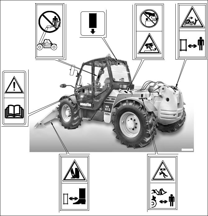
2.1 SAFETY, NOISE AND VIBRATION PLATES
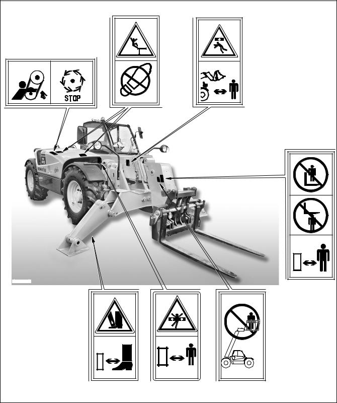
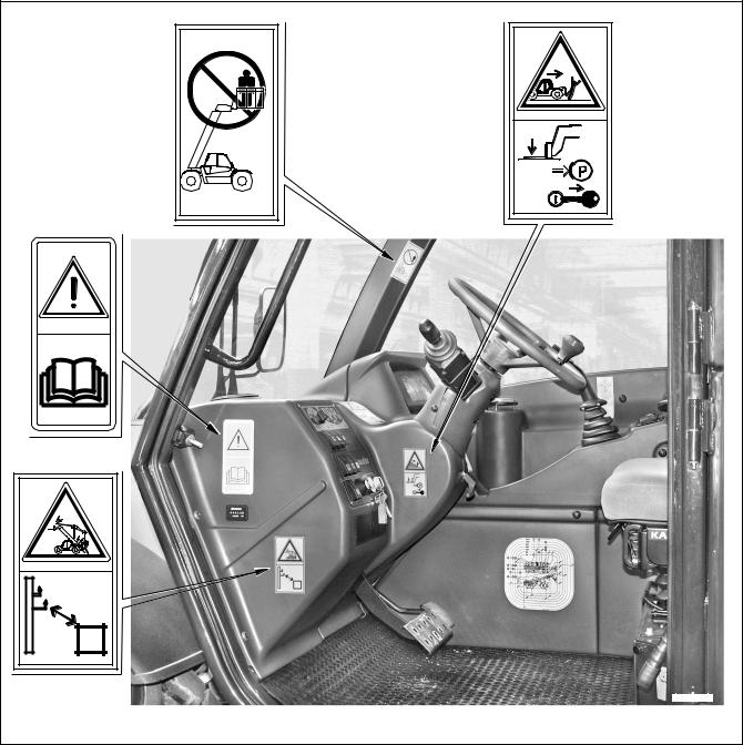
2.1.1 POSITION OF THE SAFETY PLATES
•The safety plates must always be legible and in good conditions; for this reason, if they are dirty with dust, oil or grease, it is necessary to clean them with a solution made of water and detergent.
Do not use fuel, petrol or solvents.
•If the plates are damaged, ask for new ones to Komatsu Utility or to your Komatsu Utility Dealer.
•In case of replacement of a component provided with a safety plate, make sure that this plate is applied also to the new piece.
•The machine can be provided with other plates in addition to those indicated below: keep also to the instructions given in the additional plates, in any case.
RKAA0390 |
20 |
SAFETY, NOISE AND VIBRATION PLATES
395-93-11391 |
RKAA0400 |
21 |

SAFETY, NOISE AND VIBRATION PLATES
RKAA0740 |
RKAA0720 |
22 |
SAFETY, NOISE AND VIBRATION PLATES
RKAA0710 |
23
SAFETY, NOISE AND VIBRATION PLATES
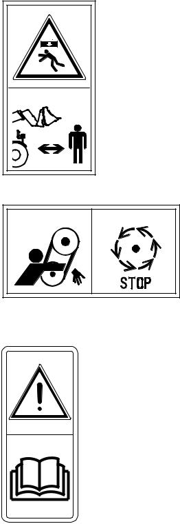
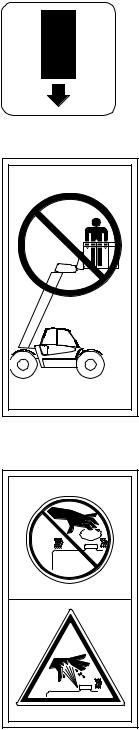
2.1.2 PICTOGRAMS AND RELEVANT MEANINGS
The warning and danger signs applied onto the machine are accompanied by or illustrated through pictograms. The personnel in charge with handling and maintenance operations must know the symbols contained in the pictograms perfectly; the symbols and the relevant meanings are explained in the following list.
WORK AREA
•Do not stand within the operating range of the equipment when it is lifted and loaded.
395-93-11361 |
RKA00150 |
DO NOT OPEN THE HOOD
• Do not open or remove the hood while the engine is running.
20M-98-RB26071
RKA00140
CONSULT THE MANUAL
•Carefully read the contents of the manual before using the machine or performing maintenance operations.
37A-98-12280
RKA00130
24
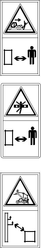
SAFETY DISTANCE
• Do not get near or stand within the machine operating area.
RISK OF ELECTROCUTION
SAFETY, NOISE AND VIBRATION PLATES
395-93-11400 |
RKA00160 |
395-93-11920 |
RKA01670 |
395-93-11351 |
RKA00170 |
25
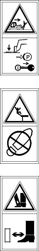
BEFORE LEAVING THE WORK POSITION
DO NOT CLIMB ON THE ENGINE HOOD
RISK OF CRUSHING
SAFETY, NOISE AND VIBRATION PLATES
395-93-11341 |
RKA00180 |
395-93-11391 |
RKA00700 |
395-93-11380 |
RKA00690 |
26
SAFETY, NOISE AND VIBRATION PLATES
EMERGENCY EXIT
DO NOT USE AS A PLATFORM
DO NOT OPEN THE RADIATOR AND THE HYDRAULIC OIL TANK WHEN THE ENGINE IS HOT
20N-98-RB26101 |
RKA00520 |
395-93-11511 |
RKA00790 |
395-93-11320
RKA00660
27
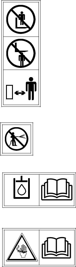
KEEP AT A SAFETY DISTANCE FROM THE EQUIPMENT – DO NOT CLIMB ON THE FORKS, NOR STAND UNDER THEM
SAFETY, NOISE AND VIBRATION PLATES
395-93-11471 |
RKA00770 |
DO NOT WASH THE ENGINE CENTRAL UNIT WITH HIGH-PRESSURE JETS
395-93-11491 |
RKA00780 |
FILLING THE HYDRAULIC SYSTEM WITH
OIL
•Only for machines in which synthetic biodegradable oil type HEES is used.
BIO-OIL
RKA00630
PRECAUTIONS TO BE TAKEN WHEN HANDLING THE BATTERY
395-93-11370 |
RKA00680 |
28
Loading...