


 Loading...
Operation & |
EEAM006011 |
|
|
||
Maintenance Manual |
|
|
|
|
|
|
|
|
|
|
|
|
|
|
|
|
|
|
|
|
PC210, PC210LC-6K
PC240LC,PC240NLC-6K
HYDRAULIC EXCAVATOR
SERIAL NUMBER |
|
PC210-6K |
- K34552 and up |
PC210LC-6K |
- K34552 and up |
PC240LC-6K |
- K34227 and up |
PC240NLC-6K |
- K34227 and up |
WARNING
Unsafe use of this machine may cause serious injury or death. Operators and maintenance personnel must read this manual before operating or maintaining this machine. This manual should be kept inside the cab for reference and periodically reviewed by all personel who will come into contact with the machine.

FOREWORD
FOREWORD
This manual provides rules and guidelines which will help you use this machine safely and effectively. Keep this manual handy and have all personnel read it periodically. If this manual has been lost or has become dirty and can not be read, request a replacement manual from Komatsu or your Komatsu distributor.
If you sell the machine, be sure to give this manual to the new owners.
Continuing improvements in the design of this machine can lead to changes in detail which may not be reflected in this manual. Consult Komatsu or your Komatsu distributor for the latest available information for your machine or for questions regarding information in this manual.
 WARNING
●This operation & maintenance manual may contain attachments and optional equipment that are not available in your area. Please consult your local Komatsu distributor for those items you require.
●This machine complies with EC directive (89/392/EEC). Machines complying with this directive display the CE mark
●Improper operation and maintenance of this machine can be hazardous and could result in serious injury or death.
●Operators and maintenance personnel should read this manual thoroughly before beginning operation or maintenance.
●Some actions involved in operation and maintenance of the machine can cause a serious accident, if they are not done in a manner described in this manual.
●The procedures and precautions given in this manual apply only to intended uses of the machine. If you use your machine for any unintended uses that are not specifically prohibited, you must be sure that it is safe for you and others. In no event should you or others engage in prohibited uses or actions as described in this manual.
●Komatsu delivers machines that comply with all applicable regulations and standards of the country to which it has been shipped. If this machine has been purchased in another country or purchased from someone in another country, it may lack certain safety devices and specifications that are necessary for use in your country. If there is any question about whether your product complies with the applicable standards and regulations of your country, consult Komatsu or your Komatsu distributor before operating the machine.
●The description of safety is given in see “SAFETY INFORMATION” on page 2. and in "SAFETY" from page 17.
1

SAFETY INFORMATION
SAFETY INFORMATION
SAFETY MESSAGES
Most accidents are caused by the failure to follow fundamental safety rules for the operation and maintenance of machines.
To avoid accidents, read, understand and follow all precautions and warnings in this manual and on the machine before performing operation and maintenance.
To identify hazards on the machine pictorial decals are used (see “POSITION FOR ATTACHING SAFETY LABELS” on page 49).
 RED WARNING TRIANGLE - This is used on safety labels where there is a high probability of serious injury or death if the hazard is not avoided. These safety messages or labels usually describe precautions that must be taken to avoid the hazard. Failure to avoid this hazard may also result in serious damage to the machine.
 ORANGE WARNING TRIANGLE - This is used on safety labels where there is a potentially dangerous situation which could result in serious injury or death if the hazard is not avoided. These safety messages or labels usually describe precautions that must be taken to avoid the hazard. Failure to avoid this hazard may also result in serious damage of the machine
 YELLOW SAFETY TRIANGLE - This is used on safety labels for hazards which could result in minor or moderate injury if the hazard is not avoided. This word might also be used for a hazard where the only result could be damage to the machine.
NOTICE
This word is used for precautions that must be taken to avoid actions which could shorten the life of the machine.
Safety precautions are described in "SAFETY" from page 17.
Komatsu cannot predict every circumstance that might involve a potential hazard in operation and maintenance. Therefore the safety message in this manual and on the machine may not include all possible safety precautions. If any procedures or actions not specifically recommended or allowed in this manual are used, you must be sure that you and others can do such procedures and actions safely and without damaging the machine. If you are unsure about the safety of some procedures, contact Komatsu or your Komatsu distributor.
2

SAFETY INFORMATION
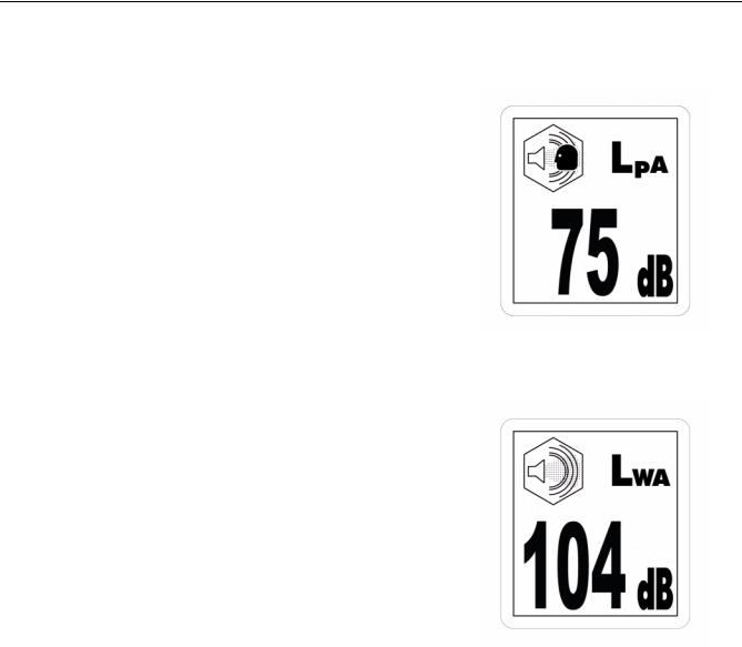
NOISE PC210, PC210LC-6K
Valid until 31 December 2001
●Operator ears noise value (Sound pressure level)
LpA
95/27/EC
●Ambient noise value (Sound power level)
LWA
105
95/27/EC
Noise level indicated is the guaranteed value as specified in the directive 86/662/EEC as amended by 95/27/EC
3
SAFETY INFORMATION
Valid as of 1 January 2002
●Sound pressure level at the operator's station, measured according to ISO6396 (Dynamic test method, simulated working cycle)
●Sound power level emitted. This is the guaranteed value as specified in European directive 2000/14/EC.
4

SAFETY INFORMATION
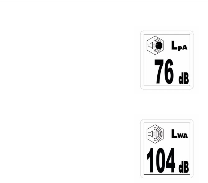
NOISE PC240LC, PC240NLC-6K
Valid until 31 December 2001
●Operator ears noise value (Sound pressure level)
LpA
95/27/EC
●Ambient noise value (Sound power level)
LWA
105
95/27/EC
Noise level indicated is the guaranteed value as specified in the directive 86/662/EEC as amended by 95/27/EC
5
SAFETY INFORMATION
Valid as of 1 January 2002
●Sound pressure level at the operator's station, measured according to ISO6396 (Dynamic test method, simulated working cycle)
●Sound power level emitted. This is the guaranteed value as specified in European directive 2000/14/EC.
VIBRATION
The weighted root mean square acceleration value to which the operator’s arms are subjected does not exceed 2.5 m/s²
The weighted root mean square acceleration value to which the operator’s body is subjected does not exceed 0.5 m/s²
These results were obtained by accelerometers during trench digging.
6

INTRODUCTION
INTRODUCTION
INTENDED USE
This Komatsu HYDRAULIC EXCAVATOR is designed to be used mainly for the following work:
●Digging
●Smoothing work
●Ditching work
●Loading work
See the section “WORK POSSIBLE USING HYDRAULIC EXCAVATOR” on page 129 for further details
FEATURES
●This Komatsu HYDRAULIC EXCAVATOR is equipped with various controls based on an advanced electronics system.
●The monitor panel greatly facilitates daily maintenance and self-diagnosis.
●Working mode, travel speed and swing priority are selectable.
●Digging and lifting force can be increased by light-touch control. (For details, see operation section.)
●Adjustable wrist control levers make operations smooth and easy.
●Fresh filtered air conditioner assures comfortable operation.
●Low noise level and smart urban style design and colouring.
●Superb operation performance provided by powerful engine and high-performance hydraulic pumps.
●Low fuel consumption controlled by an electronic control system provides an environment-friendly machine.
7

INTRODUCTION
BREAKING IN YOUR NEW MACHINE
Your Komatsu machine has been thoroughly adjusted and tested before shipment.
However, operating the machine under severe conditions at the beginning can adversely affect the performance and shorten the machine life.
Be sure to break in the machine for the initial 100 hours (as indicated by the hour meter.)
During breaking in:
●Idle the engine for 5 minutes after starting it up.
●Avoid operation with heavy loads or at high speeds.
●Sudden starting or acceleration, unnecessarily abrupt braking and sharp turning should be avoided except in cases of emergency.
Additionally for the first 20 hours
●Avoid operating engine for prolonged periods at constant speed (including idle.)
●Avoid high speed travelling for periods of more than 5 minutes.
Pay particular attention to oil pressure and temperature indicators & check coolant and oil levels frequently during breaking in.
The precautions given in this manual for operating, maintenance, and safety procedures are only those that apply when this product is used for the specified purpose. If the machine is used for a purpose that is not listed in this manual, Komatsu cannot bear any responsibility for safety. All consideration of safety in such operations is the responsibility of the user.
Operations that are prohibited in this manual must never be carried out under any circumstances.
8
LOCATION OF PLATES, TABLES TO ENTER SERIAL NO. AND DISTRIBUTOR
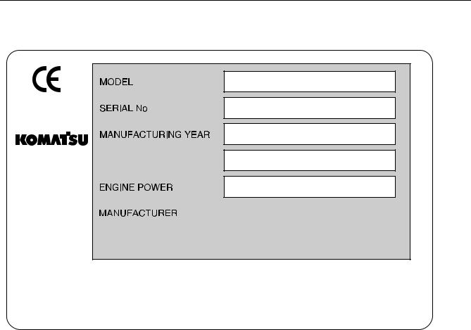
LOCATION OF PLATES, TABLES TO ENTER SERIAL NO. AND DISTRIBUTOR
MACHINE SERIAL NO. PLATE POSITION
On the front bottom right of the operator’s cab
AM088910
ENGINE SERIAL NO. PLATE POSITION
On the upper side of the engine cylinder head cover.
TABLE TO ENTER SERIAL NO. AND DISTRIBUTOR
Machine serial No.
Engine serial No.
Manufacturers name: |
KOMATSU UK Ltd. |
Address: |
Durham Road |
|
Birtley |
|
Chester-Le street |
|
County Durham DH32QX |
United Kingdom
Distributor
Address
Phone
9
LOCATION OF PLATES, TABLES TO ENTER SERIAL NO. AND DISTRIBUTOR
MACHINE SERIAL PLATE.
MASS
Komatsu UK Ltd, Birtley, Co. Durham, United Kingdom
205-00-K1290
10

CONTENTS |
|
FOREWORD ........................................................................................................................................................... |
1 |
SAFETY INFORMATION ........................................................................................................................................ |
2 |
SAFETY MESSAGES .................................................................................................................................. |
2 |
NOISE PC210, PC210LC-6K ........................................................................................................................ |
3 |
NOISE PC240LC, PC240NLC-6K ................................................................................................................ |
5 |
VIBRATION ................................................................................................................................................... |
6 |
INTRODUCTION ..................................................................................................................................................... |
7 |
INTENDED USE ........................................................................................................................................... |
7 |
FEATURES ................................................................................................................................................... |
7 |
BREAKING IN YOUR NEW MACHINE ........................................................................................................ |
8 |
LOCATION OF PLATES, TABLES TO ENTER SERIAL NO. |
|
AND DISTRIBUTOR ............................................................................................................................................... |
9 |
MACHINE SERIAL NO. PLATE POSITION .................................................................................................. |
9 |
ENGINE SERIAL NO. PLATE POSITION .................................................................................................... |
9 |
TABLE TO ENTER SERIAL NO. AND DISTRIBUTOR ................................................................................ |
9 |
MACHINE SERIAL PLATE. ........................................................................................................................ |
10 |
SAFETY.............................................................................................................. |
17 |
GENERAL PRECAUTIONS ................................................................................................................................. |
18 |
PRECAUTIONS DURING OPERATION .............................................................................................................. |
26 |
BEFORE STARTING ENGINE ................................................................................................................... |
26 |
OPERATING MACHINE ............................................................................................................................. |
28 |
TRANSPORTATION ................................................................................................................................... |
35 |
BATTERY ................................................................................................................................................... |
36 |
TOWING ..................................................................................................................................................... |
37 |
BUCKET WITH HOOK ................................................................................................................................ |
38 |
PRECAUTIONS FOR MAINTENANCE ................................................................................................................ |
41 |
BEFORE CARRYING OUT MAINTENANCE ............................................................................................. |
41 |
DURING MAINTENANCE ........................................................................................................................... |
44 |
POSITION FOR ATTACHING SAFETY LABELS ................................................................................................ |
49 |
POSITION FOR ATTACHING SAFETY LABELS ....................................................................................... |
49 |
OPERATION....................................................................................................... |
55 |
GENERAL VIEW .................................................................................................................................................. |
56 |
GENERAL VIEW OF MACHINE ................................................................................................................. |
56 |
GENERAL VIEW OF CONTROLS AND GAUGES ..................................................................................... |
57 |
11

EXPLANATION OF COMPONENTS .................................................................................................................... |
59 |
MACHINE MONITOR ................................................................................................................................. |
59 |
METERS ..................................................................................................................................................... |
65 |
SWITCHES ................................................................................................................................................. |
70 |
CONTROL LEVERS, PEDALS ................................................................................................................... |
76 |
AIR CONDITIONER .................................................................................................................................... |
87 |
CAB RADIO ................................................................................................................................................ |
90 |
FUSE .......................................................................................................................................................... |
91 |
FUSIBLE LINK ............................................................................................................................................ |
92 |
CONTROLLERS ......................................................................................................................................... |
92 |
TOOL BOX .................................................................................................................................................. |
92 |
REFUELLING PUMP .................................................................................................................................. |
93 |
HANDLING THE ACCUMULATOR ............................................................................................................ |
94 |
OPERATION ......................................................................................................................................................... |
95 |
CHECK BEFORE STARTING ENGINE ...................................................................................................... |
95 |
STARTING ENGINE ................................................................................................................................. |
106 |
OPERATIONS AND CHECKS AFTER STARTING ENGINE ................................................................... |
108 |
MOVING MACHINE OFF .......................................................................................................................... |
114 |
STEERING MACHINE .............................................................................................................................. |
117 |
STOPPING MACHINE .............................................................................................................................. |
119 |
SWINGING ............................................................................................................................................... |
120 |
OPERATION OF WORK EQUIPMENT .................................................................................................... |
121 |
HANDLING ACTIVE MODE ...................................................................................................................... |
122 |
WORKING MODE SELECTION ............................................................................................................... |
123 |
PROHIBITIONS FOR OPERATION ......................................................................................................... |
125 |
PRECAUTIONS FOR OPERATION ......................................................................................................... |
127 |
PRECAUTIONS WHEN TRAVELLING UP OR DOWN HILLS ................................................................. |
128 |
HOW TO ESCAPE FROM MUD ............................................................................................................... |
129 |
WORK POSSIBLE USING HYDRAULIC EXCAVATOR ........................................................................... |
129 |
REPLACEMENT AND INVERSION OF BUCKET .................................................................................... |
131 |
PARKING THE MACHINE ........................................................................................................................ |
133 |
CHECK AFTER FINISHING WORK ......................................................................................................... |
134 |
STOPPING ENGINE ................................................................................................................................. |
134 |
CHECK AFTER STOPPING ENGINE ...................................................................................................... |
135 |
TRANSPORTATION ........................................................................................................................................... |
137 |
LOADING, UNLOADING WORK .............................................................................................................. |
137 |
COLD WEATHER OPERATION ........................................................................................................................ |
142 |
PRECAUTIONS FOR LOW TEMPERATURE .......................................................................................... |
142 |
PRECAUTIONS AFTER COMPLETION OF WORK ................................................................................ |
143 |
LONG-TERM STORAGE .................................................................................................................................... |
145 |
BEFORE STORAGE ................................................................................................................................. |
145 |
DURING STORAGE ................................................................................................................................. |
145 |
AFTER STORAGE .................................................................................................................................... |
146 |
STARTING MACHINE AFTER LONG-TERM STORAGE ........................................................................ |
146 |
12

TROUBLESHOOTING ........................................................................................................................................ |
147 |
PHENOMENA THAT ARE NOT FAILURES ............................................................................................. |
147 |
METHOD OF TOWING MACHINE ........................................................................................................... |
147 |
USING METHOD FOR LIGHT-WEIGHT TOWING HOLE ........................................................................ |
148 |
PRECAUTIONS ON PARTICULAR JOBSITES ....................................................................................... |
148 |
IF BATTERY IS DISCHARGED ................................................................................................................ |
149 |
OTHER TROUBLE ................................................................................................................................... |
152 |
OPERATION INSTRUCTIONS FOR HIGH REACH WORK EQUIPMENT FOR PC240-6 ................................ |
157 |
PRECAUTIONS WHEN OPERATING ...................................................................................................... |
157 |
CHECK BEFORE STARTING .................................................................................................................. |
163 |
OPERATION ............................................................................................................................................. |
164 |
RAISING WORK EQUIPMENT ................................................................................................................. |
165 |
WORKING RANGE AND USING RANGE OF BOOM .............................................................................. |
165 |
WORKING RANGE AND RANGE OF USE OF BOOM ............................................................................ |
166 |
TRANSPORTATION (HIGH REACH DEMOLITION) ............................................................................... |
167 |
MAINTENANCE ............................................................................................... |
169 |
GUIDES TO MAINTENANCE ............................................................................................................................. |
170 |
OUTLINES OF SERVICE ................................................................................................................................... |
173 |
OUTLINE OF OIL, FUEL, COOLANT ....................................................................................................... |
173 |
EXPLANATION OF LUBRICATION CHART DECAL ............................................................................... |
176 |
OUTLINE OF ELECTRICAL SYSTEM ..................................................................................................... |
178 |
OUTLINE OF HYDRAULIC SYSTEM ....................................................................................................... |
178 |
WEAR PARTS LIST ........................................................................................................................................... |
180 |
USE OF FUEL, COOLANT AND LUBRICANTS ACCORDING TO AMBIENT TEMPERATURE .................... |
181 |
STANDARD TIGHTENING TORQUES FOR BOLTS AND NUTS ..................................................................... |
185 |
LIST OF NECESSARY TOOLS ................................................................................................................ |
185 |
TORQUE LIST .......................................................................................................................................... |
186 |
PERIODIC REPLACEMENT OF SAFETY CRITICAL PARTS .......................................................................... |
187 |
MAINTENANCE SCHEDULE CHART ............................................................................................................... |
190 |
MAINTENANCE SCHEDULE CHART |
|
|
190 |
MAINTENANCE WHEN USING HYDRAULIC BREAKER ....................................................................... |
193 |
SERVICE PROCEDURE .................................................................................................................................... |
194 |
INITIAL 250 HOURS SERVICE ................................................................................................................ |
194 |
WHEN REQUIRED ................................................................................................................................... |
194 |
CHECK BEFORE STARTING .................................................................................................................. |
206 |
EVERY 100 HOURS SERVICE ............................................................................................................... |
211 |
EVERY 250 HOURS SERVICE ................................................................................................................ |
214 |
EVERY 500 HOURS SERVICE ................................................................................................................ |
218 |
13

EVERY 1000 HOURS SERVICE .............................................................................................................. |
224 |
EVERY 2000 HOURS SERVICE .............................................................................................................. |
227 |
EVERY 4000 HOURS SERVICE .............................................................................................................. |
229 |
EVERY 5000 HOURS SERVICE .............................................................................................................. |
229 |
SPECIFICATIONS............................................................................................ |
233 |
SPECIFICATIONS .............................................................................................................................................. |
234 |
PC210-6K, PC210LC-6K .......................................................................................................................... |
234 |
SPECIFICATIONS .............................................................................................................................................. |
238 |
PC240LC-6K, PC240NLC-6K ................................................................................................................... |
238 |
explanation of LIFTING CAPACITY CHART ............................................................................................ |
241 |
OPTIONS, ATTACHMENTS ............................................................................ |
251 |
PRECAUTIONS RELATED TO SAFETY ........................................................................................................... |
252 |
PRECAUTIONS WHEN INSTALLING ATTACHMENTS .......................................................................... |
253 |
HANDLING BUCKET WITH HOOK ................................................................................................................... |
254 |
CHECKING FOR DAMAGE TO BUCKET WITH HOOK .......................................................................... |
254 |
PROHIBITED OPERATIONS ................................................................................................................... |
254 |
PRECAUTIONS DURING OPERATIONS ................................................................................................ |
254 |
MACHINES READY FOR ATTACHMENTS ...................................................................................................... |
255 |
EXPLANATION OF COMPONENTS ........................................................................................................ |
255 |
ATTACHMENT MOUNTING/DISMOUNTING PROCEDURE .................................................................. |
259 |
INTRODUCTION OF ATTACHMENTS .............................................................................................................. |
264 |
SPECIFICATION, USE ............................................................................................................................. |
264 |
ATTACHMENT INSTALLATION COMBINATION TABLE ........................................................................ |
266 |
SELECTION OF TRACK SHOES ............................................................................................................. |
268 |
SELECTION OF BUCKET TEETH ........................................................................................................... |
270 |
HANDLING TRAPEZOIDAL BUCKET ...................................................................................................... |
270 |
USING THE EXTENSION ARM ................................................................................................................ |
272 |
HANDLING THE CLAMSHELL BUCKET ................................................................................................. |
272 |
EXTENDING MACHINE SERVICE LIFE ............................................................................................................ |
273 |
HYDRAULIC BREAKER ........................................................................................................................... |
273 |
POWER RIPPER ...................................................................................................................................... |
277 |
MAIN FIELDS OF APPLICATIONS .......................................................................................................... |
277 |
FORK GRAB ............................................................................................................................................. |
278 |
GRAPPLE BUCKET ................................................................................................................................. |
280 |
SCRAP GRAPPLE .................................................................................................................................... |
281 |
CRUSHER & SMASHER .......................................................................................................................... |
283 |
HYDRAULIC PILE DRIVER ...................................................................................................................... |
284 |
HYDRAULIC EXCAVATOR WITH MULTIPURPOSE CRANE ................................................................. |
286 |
14

2-PC BOOM .............................................................................................................................................. |
288 |
6.4 M STRAIGHT BOOM .......................................................................................................................... |
293 |
FRONT DOZER BLADE ........................................................................................................................... |
298 |
15

16

SAFETY
 WARNING
Read and follow all safety precautions. Failure to do so may result in serious injury or death.
This safety section also contains precautions for optional equipment and attachments.
17
GENERAL PRECAUTIONS |
SAFETY |
WARNING: For reasons of safety, always follow these safety precautions.
GENERAL PRECAUTIONS
SAFETY RULES
●ONLY trained and authorised personnel can operate and maintain the machine.
●Follow all safety rules, precautions and instructions when operating or performing maintenance on the machine.
●When working with another operator or a person on worksite traffic duty, be sure all personnel understand all hand signals that are to be used.
●A seat belt must be worn at all times when operating machinery.
SAFETY LABELS
●Please read and understand the safety labels stuck to the machine.
●Always keep the safety labels clean.
●If the safety label comes off or is lost or damaged, stick it on again or contact your Komatsu distributor and replace it with a new part.
SAFETY FEATURES
●Be sure all guards and covers are in their proper position. Have guards and covers repaired if damaged.
●Use safety features such as safety lock lever properly.
●NEVER remove any safety features. ALWAYS keep them in
good operating condition.
Safety lever, see “PARKING THE MACHINE” on page 133.
Seat belt → see “USING THE SEAT BELT” on page 103.
AB30576C
●Improper use of safety features could result in serious bodily injury or death.
18
SAFETY |
GENERAL PRECAUTIONS |
WARNING: Failure to follow these safety precautions may lead to a serious accident.
CLOTHING AND PERSONAL PROTECTIVE ITEMS
●Avoid loose clothing, jewellery, and loose long hair. They can catch on controls or in moving parts and cause serious injury or death. Also, do not wear oily cloths because they are flam-
mable.
● Wear a hard hat, safety glasses, safety shoes, mask or gloves when operating or maintaining the machine. Always wear safety goggles, hard hat and heavy gloves if your job involves scattering metal chips or minute materials <—> this is so particularly when driving pins with a hammer and when cleaning the air cleaner element with compressed air.
●Check also that there is no one near the machine.
Driving in pins, see “REPLACEMENT AND INVERSION OF BUCKET” on page 131.
Cleaning of air cleaner element, see “WHEN REQUIRED” on page 194.
UNAUTHORISED MODIFICATION
Any modification made without authorisation from Komatsu can create hazards.
Before making a modification, consult your Komatsu distributor. Komatsu will not be responsible for any injury or damage caused by any unauthorised modification.
ALWAYS APPLY LOCK WHEN LEAVING OPERATOR’S SEAT
●When standing up from the operator’s seat, always place the safety lock lever securely in the LOCK position. If you accidentally touch the travel or swing lever when they are not locked, the work equipment may suddenly move and cause serious injury or damage.
● When leaving the machine, lower the work equipment completely to the ground, set the safety lock lever to the LOCK position, then stop the engine and use the key to lock all the equipment. Always take the key with you.
Work equipment posture see “PARKING THE MACHINE” |
AB30576C |
|
|
on page 133. |
|
19

GENERAL PRECAUTIONS |
SAFETY |
WARNING: For reasons of safety, always follow these safety precautions.
MOUNTING AND DISMOUNTING
●NEVER jump on or off the machine. NEVER get on or off a moving machine.
● When mounting or dismounting, always face the machine and use the handrails, machine or track frame steps, and track shoes.
● Do not hold any control levers when getting on or off the machine.
AM088940
●Ensure safety by always maintaining at least three-point contact of hands and feet with the handrails, steps or track shoes.
●Always remove any oil or mud from the handrails, steps and
track shoes. If they are damaged, repair them and tighten any loose bolts.
AM088950
●If grasping the door handrail when mounting or dismounting or moving on the track, open and lock the door securely in the open position. Otherwise, the door may move suddenly, causing you to lose balance and fall.
FIRE PREVENTION FOR FUEL AND OIL
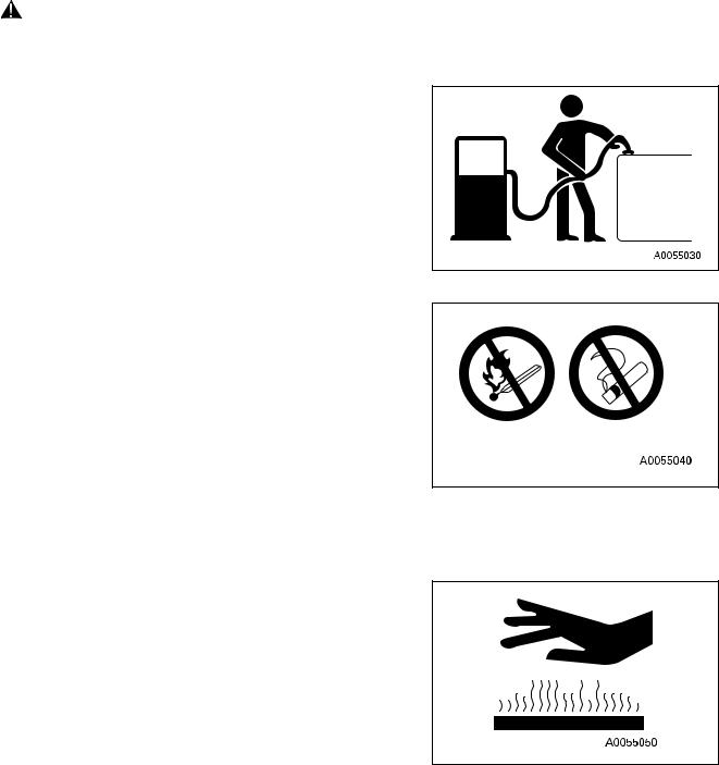
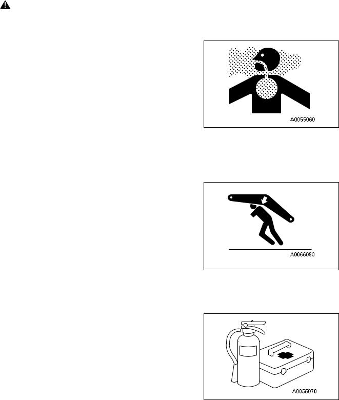
Fuel, oil, and antifreeze can be ignited by a flame. Fuel is particularly FLAMMABLE and can be HAZARDOUS.
● Keep flames away from flammable fluids.
● Stop the engine and do not smoke when refuelling.
20
SAFETY |
GENERAL PRECAUTIONS |
WARNING: Failure to follow these safety precautions may lead to a serious accident.
Tighten all fuel and oil caps securely.
Refuelling and oiling should be carried out in well ventilated areas.
Keep oil and fuel in a secure place and do not allow unauthorised persons to enter.
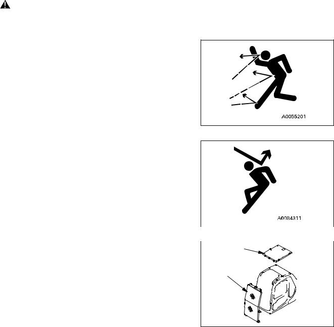
PRECAUTIONS WHEN HANDLING AT HIGH TEMPERATURES
Immediately after operations are stopped, the engine coolant, engine oil, and hydraulic oil are at high temperatures, and are still under pressure. Attempting to remove the cap, drain the oil or water, or replace the filters may lead to serious burns. Always wait for the temperature to go down, and follow the specified procedures when carrying out these operations.
To prevent hot water from spurting out:
Turn engine off.
Allow water to cool.
Slowly loosen cap to relieve pressure before removing.
To prevent hot oil from spurting out:
Turn engine off.
Allow oil to cool.
Slowly loosen cap to relieve pressure before removing.
21
GENERAL PRECAUTIONS |
SAFETY |
WARNING: For reasons of safety, always follow these safety precautions.
ASBESTOS DUST HAZARD PREVENTION
Asbestos dust can be HAZARDOUS to your health if it is inhaled.
Your Komatsu machine and genuine Komatsu spare parts do not contain any asbestos. Use only genuine Komatsu spare parts. If spare parts containing asbestos are used, the following precautions must be observed:
● NEVER use compressed air for cleaning.
●Use water for cleaning to keep down the dust.
● Operate the machine with the wind to your back, whenever possible.
●Use an approved respirator if necessary.
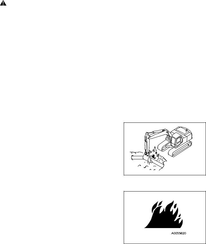
CRUSHING OR CUTTING PREVENTION
Do not enter, or put your hand or arm or any other part of your body between movable parts such as between the work equipment and cylinders, or between the machine and work equipment.
If the work equipment is operated, the clearance will change and this may lead to serious damage or personal injury.
FIRE EXTINGUISHER AND FIRST AID KIT
Know how to use fire extinguisher (if installed).
Provide a first aid kit at the storage point.
Know what to do in the event of a fire.
Be sure you know the phone numbers of persons you should contact in case of an emergency.
22
SAFETY |
GENERAL PRECAUTIONS |
WARNING: Failure to follow these safety precautions may lead to a serious accident.
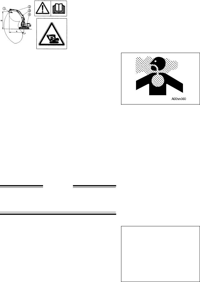
PROTECTION AGAINST FALLING OR FLYING OBJECTS
If there is any danger of falling or flying objects hitting the operator, install protective guards in place to protect the operator as required for each particular situation.
● For work with breakers, install a front guard on the windshield. Also, place a laminate coating sheet over the windshield.
● For demolition or shear work, install a front guard on the windshield and a top guard on the cab. Also, place a laminate coating sheet over the windshield.
●For work in mines, quarries, demolition, tunnels or other places where there is danger of falling rocks, put FOPS (falling object protective structure) in place. Also, place a laminate coating sheet over the windshield.
The above comments are made with regards to typical work- |
|
|
ing conditions. By all means you should put on other guards if |
|
|
required by conditions at your particular site. |
|
|
For details of safety guards, please contact your Komatsu dis- |
|
|
tributor. |
|
|
Also, even for other types of work, if there is any danger of |
|
|
|
||
being hit by falling or flying objects or of objects entering the |
|
|
(B) |
||
operator’s cab, select and install a guard that matches the |
||
|
||
working conditions. |
|
|
Be sure to close the front window before commencing work. |
(C) |
|
|
||
Level 1 acceptance is intended for protection from small fall- |
|
|
ing rocks, flying objects and other debris encountered in oper- |
|
|
ations such as highway maintenance, landscaping and light |
|
|
construction site services |
|
AB30052C
Level 1 Guards:
Fitted directly onto the roof and front of the cab.
(B): Top guard |
(C): Front guard (I) |
|
|
23
GENERAL PRECAUTIONS |
SAFETY |
WARNING: For reasons of safety, always follow these safety precautions.
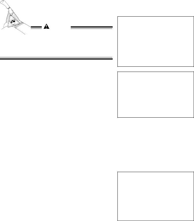
When carrying out the above operations, make sure to keep all persons other than the operator outside the range of falling
or flying objects. Be particularly sure to maintain a proper dis- (A) tance when carrying out shear operations.
(A): FOPS |
(B) Front guard |
(B) |
|
||
|
|
|
Level 2 acceptance is intended for protection from large falling rocks, flying objects and other debris encountered in oper-
ations such as demolition work, building constructions and
AB30053C
general heavy site work.
Level 2 Guards
Fops fitted directly to the revolving frame
Front guard fitted directly to front of the fops
NOTE: The above guards are the minimum required for typical working conditions as described above and are in accordance with the latest requirements of ISO/DIS 10262 (draft standard).
PRECAUTIONS FOR ATTACHMENTS
●When installing and using an optional attachment, read the instruction manual for the attachment and the information related to attachments in this manual.
●Do not use attachments that are not authorised by Komatsu or your Komatsu distributor. Use of unauthorised attachments could create a safety problem and adversely affect the proper operation and useful life of the machine.
●Any injuries, accidents, product failures resulting from the use of unauthorised attachments will not be the responsibility of Komatsu.
MACHINES WITH ACCUMULATOR
On machines equipped with an accumulator, for a short time after the engine is stopped, the work equipment will lower under its own weight when the work equipment control lever is shifted to LOWER. After the engine is stopped, set the safety lock lever to the lock position (and also lock the attachment pedal with the lock pin).
When releasing the pressure inside the work equipment circuit on machines equipped with an accumulator, follow the procedure given in the inspection and maintenance section.
Method of releasing pressure see “HANDLING THE |
AB30576C |
|
|
ACCUMULATOR” on page 94. |
|
The accumulator is filled with high-pressure nitrogen gas, and it is extremely dangerous if it is handled in the wrong way. Always observe the following precautions.
24
SAFETY |
GENERAL PRECAUTIONS |
WARNING: Failure to follow these safety precautions may lead to a serious accident.
●Never make any hole in the accumulator or expose it to flame or fire.
●Do not weld anything to the accumulator.
●When carrying out disassembly or maintenance of the accumulator, or when disposing of the accumulator, it is necessary to release the gas from the accumulator. A special air bleed valve is necessary for this operation, so please contact your Komatsu distributor.
Gas in accumulator see “HANDLING THE ACCUMULATOR” on page 94.
EMERGENCY EXIT
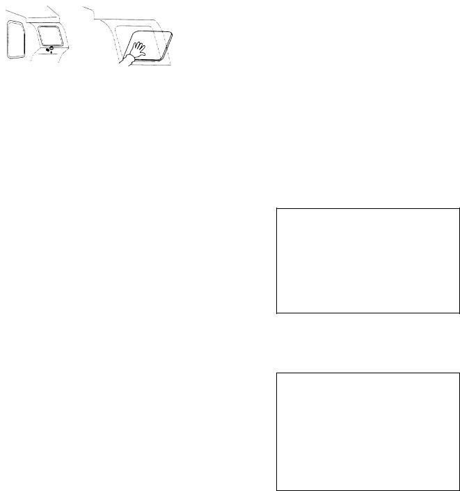
●When exit by normal means is prevented in an emergency you can get out through the emergency exit (rear window).
●Pull the ring at the bottom of the window and remove strip. This will allow you to push out glass.
ROTATING BEACON (Option)
When the machine is operated on or beside a road, a rotating beacon is required to avoid a traffic accident.
Contact your Komatsu distributor to install beacon lamp.
ELECTROMAGNETIC INTERFERENCE
When this machine is operating close to a source of high electromagnetic interference, such as a radar station, some abnormal phenomena may be observed.
●The display on the monitor panel may behave erratically.
●The warning buzzer may sound.
These effects do not signify a malfunction and the machine will return to normal as soon as the source of interference is removed.
25
PRECAUTIONS DURING OPERATION |
SAFETY |
WARNING: For reasons of safety, always follow these safety precautions.
PRECAUTIONS DURING OPERATION
BEFORE STARTING ENGINE
SAFETY AT WORKSITE
●Before starting the engine, thoroughly check the area for any unusual conditions that could be dangerous.
●Before starting the engine, examine the terrain and soil conditions of the worksite. Determine the best and safest method of operation.
●Make the slope as horizontal as possible before continuing operations.
●If you need to operate on a street, protect pedestrians and cars by designating a person for worksite traffic duty or by installing fences around the worksite.
●If water lines, gas lines, and high-voltage electrical lines may be buried under the worksite, contact each utility and identify their locations. Be careful not to sever or cut any of these lines.
●Check the depth and flow of water before operating in water or crossing a river. NEVER be in water which is in excess of the permissible water depth.
Permissible water depth see “PRECAUTIONS FOR OPERATION” on page 127.
AE341030A |
FIRE PREVENTION
●Thoroughly remove wood chips, leaves, paper and other flammable things accumulated on the engine compartment. They could cause a fire.
●Check fuel, lubrication, and hydraulic systems for leaks. Have any leaks repaired. Wipe up any excess oil, fuel or other flammable fluids.
Check point see “WALK-AROUND CHECK” on page 95.
●Be sure a fire extinguisher is present and working.
IN OPERATOR’S CAB
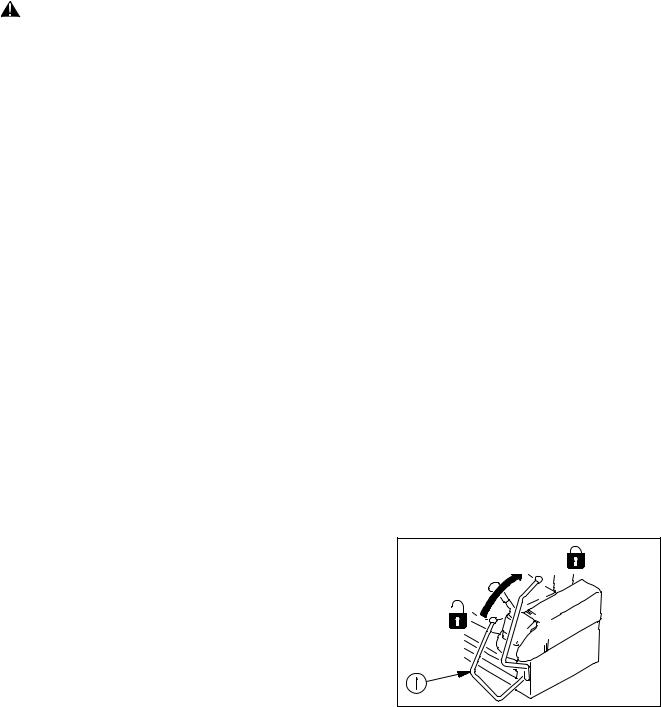
●Do not leave tools or spare parts lying around in the operator’s compartment. They may damage or break the control levers or switches. Always put them in the tool box on the left or right side of the machine.
26
SAFETY |
PRECAUTIONS DURING OPERATION |
WARNING: Failure to follow these safety precautions may lead to a serious accident.
●Keep the cab floor, controls, steps and handrails free of oil, grease, snow, and excess dirt.
Handling seat belt → see “USING THE SEAT BELT” on page 103.
VENTILATION FOR ENCLOSED AREAS
●If it is necessary to start the engine within an enclosed area,
provide adequate ventilation. Exhaust fumes from the engine can KILL.
PRECAUTIONS FOR MIRRORS, WINDOWS AND LIGHTS
● Remove all dirt from the surface of the windows and lights to ensure that you can see well.
●Adjust the rear view mirror so that you can see clearly from
the operator’s seat, and always keep the surface of the mirror clean. If any glass is broken, replace it with a new part.
●Check that the head lamps and working lamps are installed to match the operating conditions. Check also that they light up properly.
PRECAUTIONS WHEN HANDLING (TWO PIECE BOOM)
When operating the boom arm 2-piece type, select a specialist operator and do not allow any other person to operate the machine.
●Check that the ground inside the operating range is flat and firm.
●Always operate the work equipment slowly.
 WARNING
Especially when lowering the work equipment, move it as slowly as possible to prevent any shock to the machine (operate the work equipment in the same way as when operating a crane).
●Pay attention to warning decal in the cab.
27
PRECAUTIONS DURING OPERATION |
SAFETY |
WARNING: For reasons of safety, always follow these safety precautions.
WARNING |
|
If the bucket is operated in a certain way, it comes in contact |
|
with the machine body (operator’s cab, upper boom, cylin- |
|
ders and undercarriage). When operating the work equip- |
|
ment, take sufficient care not to bring it in contact with the |
|
machine body. |
Interference |
|
Interference
OPERATING MACHINE
WHEN STARTING THE ENGINE
●Walk around your machine again just before mounting it, to check for people and objects that might be in the way.
●NEVER start the engine if a warning tag has been attached to the wrist control.
●When starting the engine, sound the horn as an alert.
●Start and operate the machine only while seated.
●Fasten your seat belt securely at all times during operation.
●Do not allow anyone other than the operator to ride in the cab or on the machine body.
●For machines equipped with a travel alarm buzzer, check that the warning device operates correctly.
28
Loading...