


 Loading...
Komatsu PC210-11, PC240-11, PC290-11, PC360-11, PC390-11 Service Manual
...333514B
Mobile Lubrication Library
Komatsu PC210-11/PC240-11/PC290-11
and PC360-11/ PC390-11/PC490-11
Excavator Installation Instructions
Instructions for installing a Graco automatic lubrication system on a Komatsu PC210-11/PC240-11/PC290-11 and PC360-11/PC390-11/PC490-11 Excavator.
Part No. 17J900
Maximum System Working Pressure: 2750 psi (18.96 MPa, 189.6 bar)
Important Safety Information
 Read all warnings and instructions in all Graco related component manuals and all Komatsu equipment manuals. Save all instructions.
Related Graco Component Manuals*
Manual No. Manual Title
332291 |
G3 Pump |
3A2960 GLC2200 Controller
312497 MSP Divider Valves
*Refer to these instruction manuals for additional information related to the installation and operation of system components.
 WARNING
FLUID INJECTION HAZARD
Fluid leaks from incorrectly installed or ruptured components, and/or failure to verify the components are properly installed and tested, can result in serious injury such as fluid spraying in the eyes or on skin and fluid injection, or equipment damage. Installation must be done by a qualified professional or Komatsu certified technician and tested prior to use.
The information contained in this document is only a recommendation for an automatic lubrication system and is not intended to replace the installation and maintenance instructions provided by the original equipment manufacturer.
Table of Contents
Table of Contents
Installation Checklist . . . . . . . . . . . . . . . . . . . . . . . . 3
Recommended Tools and Supplies . . . . . . . . . . . . 4
Installation Notes . . . . . . . . . . . . . . . . . . . . . . . . 4
Typical Installation . . . . . . . . . . . . . . . . . . . . . . . . . 5
Installation . . . . . . . . . . . . . . . . . . . . . . . . . . . . . . . . 6
Before You Start . . . . . . . . . . . . . . . . . . . . . . . . . 6
Bearing Point Fittings . . . . . . . . . . . . . . . . . . . . . . . 7
MSP Divider Valves . . . . . . . . . . . . . . . . . . . . . . . . 14
MSP Valve Component Identification . . . . . . . . 14
MSP Divider Valve Assembly . . . . . . . . . . . . . . 14
MSP Divider Valve Assembly . . . . . . . . . . . . . . 16
Weld Stud Guidelines . . . . . . . . . . . . . . . . . . . . . . 17
G3 Pump . . . . . . . . . . . . . . . . . . . . . . . . . . . . . . . . . 21
G3 Mounting Bracket Installation . . . . . . . . . . . 23
Remote Fill Installation . . . . . . . . . . . . . . . . . . . . . 24
GLC2200 Controller . . . . . . . . . . . . . . . . . . . . . . . . 28
GLC2200 Controller Wiring . . . . . . . . . . . . . . . . . . 30
Hose Assemblies . . . . . . . . . . . . . . . . . . . . . . . . . . 33
Hose Assembly Instructions . . . . . . . . . . . . . . . 33
Hose Routing . . . . . . . . . . . . . . . . . . . . . . . . . . . . . 34
Hose Installation . . . . . . . . . . . . . . . . . . . . . . . . 34
Arm and Bucket Valve . . . . . . . . . . . . . . . . . . . . 37
Boom and Swing Circle Valve . . . . . . . . . . . . . . 40
GLC2200 Controller Programming . . . . . . . . . . . . 43
Filling and Purging . . . . . . . . . . . . . . . . . . . . . . . . 46
Testing . . . . . . . . . . . . . . . . . . . . . . . . . . . . . . . . . . 47
Routine Service and Equipment Maintenance . . 47
Troubleshooting . . . . . . . . . . . . . . . . . . . . . . . . . . . 48
Parts . . . . . . . . . . . . . . . . . . . . . . . . . . . . . . . . . . . . 50
Notes . . . . . . . . . . . . . . . . . . . . . . . . . . . . . . . . . . . . 51
Graco Information . . . . . . . . . . . . . . . . . . . . . . . . . 52
2 |
NOTE: Photographs may include optional equipment. |
Installation Checklist
Installation Checklist
The following checklist is provided as a tool to ensure all installation procedures are completed.
Completed |
Description |
Page |
|
|
|
|
Walk around the equipment; use a grease gun to verify that all lube points receive grease. |
6 |
|
|
|
|
Grease all zerks, before removal |
6 |
|
|
|
|
Remove zerks and Komatsu extensions. |
6 |
|
|
|
|
Install bearing point fittings |
7 |
|
|
|
|
Assemble MSP Divider Valves |
14 |
|
|
|
|
Install P-clamp, anchor and MSP valve weld studs |
19 |
|
|
|
|
Assemble the G3 pump and fittings |
21 |
|
|
|
|
Install G3 pump |
22 |
|
|
|
|
Install remote fill |
24 |
|
|
|
|
Install and route G3 power cable |
25 |
|
|
|
|
Install GLC2200 controller |
28 |
|
|
|
|
Wire GLC2200 controller and pump |
30 |
|
|
|
|
Route and wrap hoses between divider valves, bearing points and pump |
34 |
|
|
|
|
Install P-clamps, zip ties, and other anchors |
34 |
|
|
|
|
Program GLC2200 controller |
43 |
|
|
|
|
Fill the G3 pump reservoir with grease; purge the main feed lines |
46 |
|
|
|
|
Run test program; verify all connections are tight; verify all points are receiving lubricant |
47 |
|
|
|
NOTE: Photographs may include optional equipment. |
3 |

Recommended Tools and Supplies
Recommended Tools and Supplies
|
Size/Description |
||
Tool |
|
|
|
US |
|
Metric |
|
|
|
|
|
Combination wrench* |
1/4 in. - 3/4 in. |
|
6 mm - 20 mm |
Socket set, standard and deep well with ratchet* |
3/8 in. - 3/4 in. |
|
9.5 mm - 20 mm |
Screwdrivers: standard and Phillips |
1 short; 1 long |
|
|
Adjustable wrench |
1 small; 1 medium |
|
|
High speed drill (corded or cordless) |
|
|
|
Drill bit - steel, high quality |
5/16 in., 11/16 in. |
|
|
Center punch |
fine point |
|
|
Pipe taper tap |
1/8 in. NPT |
|
|
Hammer |
|
|
|
Angle grinder |
|
|
|
Grinding disc |
Heavy grade grinding disc |
||
Flap disc |
60 - 80 grit |
|
|
Cutoff disc |
High quality disc |
|
|
Cutting blade / knife |
Razor blade cutting tool |
|
|
Standard pliers |
Rubber handle |
|
|
Needle nose pliers |
Rubber handle |
|
|
Side cut pliers (diagonal cutters) |
Rubber handle |
|
|
Slip joint pliers |
Rubber handle |
|
|
Locking pliers |
Small or medium |
|
|
Electrician’s wire striper / crimper |
General duty wire striper / crimper |
||
Soldering iron |
30 watt minimum |
|
|
Electrical solder |
|
|
|
Soldering flux |
|
|
|
Shrink tubing |
Various sizes |
|
|
Electrical tape |
Black, small roll |
|
|
Thread sealant |
Liquid thread sealant such as Loctite® 656 |
||
Multi-tester / voltmeter |
Must test DC/AC/Ohms |
|
|
Electrical connectors |
Ring connectors (14 gauge) |
||
Tape measure |
Standard / metric |
|
|
Komatsu primer and paint |
Color should match the Komatsu equipment |
||
Documentation / writing implements |
Small note pad, pen, pencil, marker |
||
*Both US and Metric sizes of these tools are recommended.
Loctite® is a registered trademark of the Henkel Corporation.
All other Trademarks used herein are the property of their respective owners.
Installation Notes
• Do not use PTFE tape on fitting threads. Liquid pipe |
• Prime and paint all bare metal surfaces prior to |
sealant is recommended for use in lubrication sys- |
installation with matching Komatsu primer and paint. |
tems to eliminate the potential for contamination. If |
|
you must use PTFE tape, always skip the first two |
|
threads on the fitting. |
|
• Refer to the Installation Checklist provided on page |
|
3 to ensure all installation procedures have been |
|
completed. |
|
4 |
NOTE: Photographs may include optional equipment. |
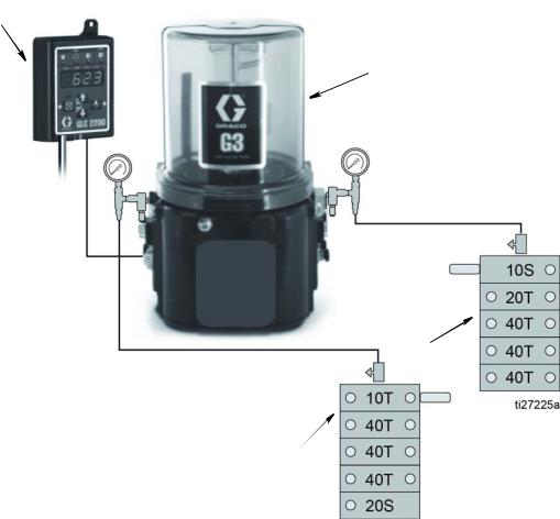
Typical Installation
Typical Installation
A
 B
B
D
C
Key
AGLC2200 Controller
BG3 Automatic Lubrication Pump
CMSP Divider Valve - Boom and Swing Circle Valve
DMSP Divider Valve - Arm and Bucket Valve
Run Time
MODEL |
Pump ON Time |
Pump OFF Time |
|
|
|
PC210-11/PC240-11 |
1 minutes and 45 seconds |
1 hour |
PC290-11/PC360-11 |
2 minutes |
1 hour |
PC390-11/PC490-11 |
2 minutes and 10 seconds |
1 hour |
NOTE: Photographs may include optional equipment. |
5 |
Installation
Installation
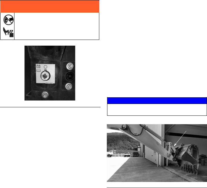
Before You Start
 WARNING
Disconnect battery before installing the lubrication equipment. Installing lubrication equipment on powered machinery could result in serious injury from skin injection or parts moving unexpectedly.
FIG. 1: Battery Disconnect
1.Walk around the machine with a grease gun and verify that every bearing point is accepting grease. (Refer to FIG. 3, page 7 to identify lubrication points). This will ensure that the valves can dispense grease to the bearing points by identifying potentially blocked passages from the grease zerk to the bearing point.
Zerk Fittings
a.Use a clean cloth or rag to remove excessive grease, contaminants and dirt from the work area.
b.Remove all grease zerks and Komatsu extensions from their installation locations.
c.Use a clean cloth or rag to remove any remaining grease, contaminants or dirt from the area around the passage way to the bearing points.
d.If required use 1/8 in. NPT pipe tap to chase the passage threads.
2.Flip over the H-link on the excavator bucket (FIG. 2). (The zerk fittings must face the inside of the arm.)
3.After the H-link is reversed, manually grease the lube points again to verify grease is being accepted.
NOTICE
It may be necessary to rotate the pins while greasing to get the grease to purge.
H-Link
FIG. 2
6 |
NOTE: Photographs may include optional equipment. |

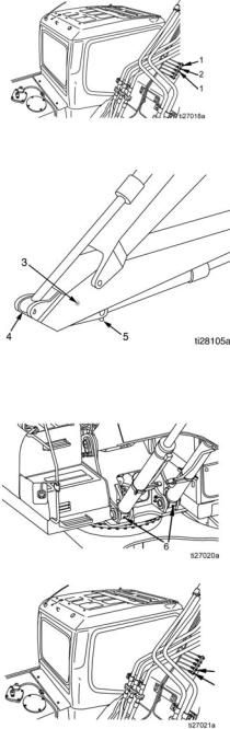
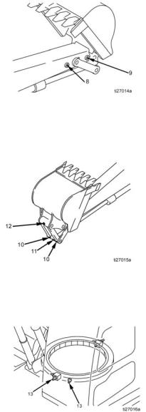
Bearing Point Fittings
Bearing Point Fittings
1.Apply thread sealant to supplied bearing point fittings.
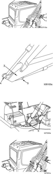
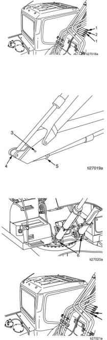
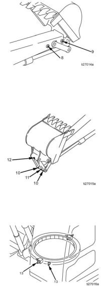
2.Install fittings in bearing points. Refer to FIG. 3 and the Bearing Point Fitting Table, page 8 for installation locations and parts.
3.Refer to Bearing Point Fitting Table, beginning on page 8, to determine the location of the bearing points on your model.
4
5
3
6
13
13 6
10 |
|
11 |
|
12 |
8 |
|
|
10 |
9 |
FIG. 3
NOTE: Photographs may include optional equipment. |
7 |
Bearing Point Fittings
Bearing Point Fittings Table: PC210-11/PC240-11 Models
NOTE: Before starting a lube cycle, set the machine to the greasing posture. If you are unsure of this procedure, see the Komatsu Excavator instruction manual.
Ref |
|
|
|
|
No. |
Location |
Part No. |
Description |
|
|
|
|
|
|
1 |
Boom cylinder rod |
17K062 |
Adapter, long, BSPT x NPT |
|
|
|
|
||
pins (2 places) |
556763 |
Elbow, JIC 90° 1/8 inch x 4 |
|
|
|
|
|||
|
|
|
||
|
|
|
|
|
2 |
Arm cylinder foot pin |
17K062 |
Adapter, long, BSPT x NPT |
|
(1 place) |
556763 |
Elbow, JIC 90° 1/8 inch x 4 |
|
|
|
|
|||
|
|
|
||
|
|
|
|
|
3 |
Boom and arm con- |
17G422 |
Adapter, short, BSPT x NPT |
|
nection pin (1 place) |
556763 |
Elbow, JIC 90° 1/8 inch x 4 |
|
|
|
|
|||
|
|
|
|
|
4† |
Arm cylinder rod |
556763 |
Elbow, JIC 90° 1/8 inch x 4 |
|
end (1 place) |
|
|||
|
|
|
|
|
|
|
|
|
|
5 |
Bucket cylinder foot |
17G422 |
Adapter, short, BSPT x NPT |
|
|
|
|
||
pin (1 place) |
556763 |
Elbow, JIC 90° 1/8 inch x 4 |
|
|
|
|
|||
|
|
|
||
|
|
|
|
|
6 |
Boom cylinder foot |
17G422 |
Adapter, short, BSPT x NPT |
|
|
|
|
||
pins (2 places) |
556763 |
Elbow, JIC 90° 1/8 inch x 4 |
|
|
|
|
|||
|
|
|
||
|
|
|
|
|
7 |
|
17K062 |
Adapter, long, BSPT x NPT |
|
|
556763 |
Elbow, JIC 90° 1/8 inch x 4 |
|
|
|
|
|
||
|
Boom foot pins (2 |
|
|
|
|
|
|
|
|
|
places) |
17K062 |
Adapter, long, BSPT x NPT |
7 |
7* |
|
17K061 |
Adapter, street elbow, BSPT x NPT |
7 |
|
|
|||
|
|
555749 |
Connector, #4, JIC, 1/8 PM |
|
|
|
|
|
|
8 |
NOTE: Photographs may include optional equipment. |
Bearing Point Fittings
8 |
Arm and link con- |
17K061 |
Adapter, street elbow, BSPT x NPT |
|
|
|
|
||
|
nection pin (1 place) |
555749 |
Connector, #4, JIC, 1/8 PM |
|
|
|
|
|
|
9 |
Arm and bucket con- |
17K061 |
Adapter, street elbow, BSPT x NPT |
|
nection pin (1 place) |
555749 |
Connector, #4, JIC, 1/8 PM |
|
|
|
|
|||
|
|
|
|
|
10 |
H-Link connecting |
17G422 |
Adapter, short, BSPT x NPT |
|
|
|
|
||
pins (2 places) |
556763 |
Elbow, JIC 90° 1/8 inch x 4 |
|
|
|
|
|||
|
|
|
||
|
|
|
|
|
11 |
Bucket cylinder rod |
17K061 |
Adapter, street elbow, BSPT x NPT |
|
|
|
|
||
|
pin (1 place) |
555749 |
Connector, #4, JIC, 1/8 PM |
|
|
|
|
||
|
|
|
|
|
12 |
Bucket and link con- |
17G422 |
Adapter, short, BSPT x NPT |
|
nection pin (1 place) |
556763 |
Elbow, JIC 90° 1/8 inch x 4 |
|
|
|
|
|||
|
|
|
|
|
13 |
Swing circle (2 |
17K062 |
Adapter, long, BSPT x NPT |
|
|
|
|
||
places) |
556763 |
Elbow, JIC 90° 1/8 inch x 4 |
|
|
|
|
|||
|
|
|
||
|
|
|
|
|
†Tap rod end with 1/8 NPT tap. Rod end may need to be flipped over to allow clearance for fittings during articulation
Grind slot in cap around zerk wide enough to tighten fittings approximately 1-1/4 inch wide.
NOTE: Photographs may include optional equipment. |
9 |
Bearing Point Fittings
Bearing Point Fittings Table: PC290-11/PC360-11 Models
NOTE: Before starting a lube cycle, set the machine to the greasing posture. If you are unsure of this procedure, see the Komatsu Excavator instruction manual.
Ref |
|
|
|
|
|
No. |
Location |
Part No. |
Description |
|
|
|
|
|
|
|
|
1 |
Boom cylinder rod |
17K062 |
Adapter, long, BSPT x NPT |
|
|
|
|
|
|||
pins (2 places) |
556763 |
Elbow, JIC 90° 1/8 inch x 4 |
|
||
|
|
||||
|
|
|
|||
|
|
|
|
|
|
2 |
Arm cylinder foot pin |
17K062 |
Adapter, long, BSPT x NPT |
|
|
(1 place) |
556763 |
Elbow, JIC 90° 1/8 inch x 4 |
|
||
|
|
||||
|
|
|
|||
|
|
|
|
|
|
3 |
Boom and arm con- |
17K061 |
Adapter, street elbow, BSPT x NPT |
|
|
nection pin (1 place) |
555749 |
Connector, #4, JIC, 1/8 PM |
|
||
|
|
||||
|
|
|
|
|
|
4† |
Arm cylinder rod |
556763 |
Elbow, JIC 90° 1/8 inch x 4 |
|
|
end (1 place) |
|
||||
|
|
|
|
||
|
|
|
|
|
|
5 |
Bucket cylinder foot |
17G422 |
Adapter, short, BSPT x NPT |
|
|
|
|
|
|||
pin (1 place) |
556763 |
Elbow, JIC 90° 1/8 inch x 4 |
|
||
|
|
||||
|
|
|
|||
|
|
|
|
|
|
6 |
Boom cylinder foot |
17G422 |
Adapter, short, BSPT x NPT |
|
|
|
|
|
|||
|
pins (2 places) |
556763 |
Elbow, JIC 90° 1/8 inch x 4 |
|
|
|
|
|
|||
|
|
|
|
|
|
|
Boom foot pins (2 |
17K062 |
Adapter, long, BSPT x NPT |
|
|
7 |
places) |
|
|||
556763 |
Elbow, JIC 90° 1/8 inch x 4 |
7 |
|||
|
|
||||
|
|
|
|
7 |
|
|
|
|
|
|
10 |
NOTE: Photographs may include optional equipment. |
Bearing Point Fittings
8 |
Arm and link con- |
17K061 |
Adapter, street elbow, BSPT x NPT |
|
|
|
|
||
|
nection pin (1 place) |
555749 |
Connector, #4, JIC, 1/8 PM |
|
|
|
|
|
|
9 |
Arm and bucket con- |
17K061 |
Adapter, street elbow, BSPT x NPT |
|
nection pin (1 place) |
555749 |
Connector, #4, JIC, 1/8 PM |
|
|
|
|
|||
|
|
|
|
|
10 |
H-Link connecting |
17G422 |
Adapter, short, BSPT x NPT |
|
|
|
|
||
pins (2 places) |
556763 |
Elbow, JIC 90° 1/8 inch x 4 |
|
|
|
|
|||
|
|
|
||
|
|
|
|
|
11 |
Bucket cylinder rod |
17K061 |
Adapter, street elbow, BSPT x NPT |
|
|
|
|
||
|
pin (1 place) |
555749 |
Connector, #4, JIC, 1/8 PM |
|
|
|
|
||
|
|
|
|
|
12 |
Bucket and link con- |
17K062 |
Adapter, long, BSPT x NPT |
|
nection pin (1 place) |
556763 |
Elbow, JIC 90° 1/8 inch x 4 |
|
|
|
|
|||
|
|
|
|
|
13 |
Swing circle (2 |
17K062 |
Adapter, long, BSPT x NPT |
|
|
|
|
||
places) |
556763 |
Elbow, JIC 90° 1/8 inch x 4 |
|
|
|
|
|||
|
|
|
||
|
|
|
|
|
† Tap rod end with 1/8 NPT tap. Rod end may need to be flipped over to allow clearance for fittings during articulation. Remove plug from cylinder end and install plug on opposite side of cylinder where zerk was located.
Grind slot in cap around zerk wide enough to tighten fittings approximately 1-1/4 inch wide.
NOTE: Photographs may include optional equipment. |
11 |
Bearing Point Fittings
Bearing Point Fittings Table: PC390-11/PC490-11 Models
NOTE: Before starting a lube cycle, set the machine to the greasing posture. If you are unsure of this procedure, see the Komatsu Excavator instruction manual.
Ref |
|
|
|
|
|
No. |
Location |
Part No. |
Description |
|
|
|
|
|
|
|
|
1 |
Boom cylinder rod |
17K062 |
Adapter, long, BSPT x NPT |
|
|
|
|
|
|||
pins (2 places) |
556763 |
Elbow, JIC 90° 1/8 inch x 4 |
|
||
|
|
||||
|
|
|
|||
|
|
|
|
|
|
2 |
Arm cylinder foot pin |
17K062 |
Adapter, long, BSPT x NPT |
|
|
(1 place) |
556763 |
Elbow, JIC 90° 1/8 inch x 4 |
|
||
|
|
||||
|
|
|
|||
|
|
|
|
|
|
3 |
Boom and arm con- |
17K061 |
Adapter, street elbow, BSPT x NPT |
|
|
nection pin (1 place) |
555749 |
Connector, #4, JIC, 1/8 PM |
|
||
|
|
||||
|
|
|
|
|
|
|
|
17K062 |
Adapter, long, BSPT x NPT |
|
|
4 |
Arm cylinder rod |
15K783 |
Elbow, street |
|
|
end (1 place) |
|
||||
|
|
|
|
||
|
|
555749 |
Connector, #4, JIC, 1/8 PM |
|
|
5 |
Bucket cylinder foot |
17G422 |
Adapter, short, BSPT x NPT |
|
|
|
|
|
|||
pin (1 place) |
556763 |
1/8 inch x 4 JIC 90° elbow |
|
||
|
|
||||
|
|
|
|||
|
|
|
|
|
|
6 |
Boom cylinder foot |
17G422 |
Adapter, short, BSPT x NPT |
|
|
|
|
|
|||
pins (2 places) |
556763 |
Elbow, JIC 90° 1/8 inch x 4 |
|
||
|
|
|
|||
|
|
|
|
|
|
7 |
Boom foot pins (2 |
17K062 |
Adapter, long, BSPT x NPT |
|
|
|
|
|
|||
places) |
556763 |
Elbow, JIC 90° 1/8 inch x 4 |
7 |
||
|
|||||
|
|
|
|
7 |
|
|
|
|
|
|
12 |
NOTE: Photographs may include optional equipment. |
Bearing Point Fittings
8 |
Arm and link con- |
17K062 |
Adapter, long, BSPT x NPT |
|
|
|
|
||
|
nection pin (1 place) |
556763 |
Elbow, JIC 90° 1/8 inch x 4 |
|
|
|
|
|
|
9 |
Arm and bucket con- |
17K061 |
Adapter, street elbow, BSPT x NPT |
|
nection pin (1 place) |
555749 |
Connector, #4, JIC, 1/8 PM |
|
|
|
|
|||
|
|
|
|
|
10 |
H-Link connecting |
17K062 |
Adapter, long, BSPT x NPT |
|
|
|
|
||
pins (2 places) |
556763 |
Elbow, JIC 90° 1/8 inch x 4 |
|
|
|
|
|||
|
|
|
||
|
|
|
|
|
11 |
Bucket cylinder rod |
17K061 |
Adapter, street elbow, BSPT x NPT |
|
|
|
|
||
|
pin (1 place) |
555749 |
Connector, #4, JIC, 1/8 PM |
|
|
|
|
||
|
|
|
|
|
12 |
Bucket and link con- |
17K062 |
Adapter, long, BSPT x NPT |
|
nection pin (1 place) |
556763 |
Elbow, JIC 90° 1/8 inch x 4 |
|
|
|
|
|||
|
|
|
|
|
13 |
Swing circle (2 |
17K062 |
Adapter, long, BSPT x NPT |
|
|
|
|
||
places) |
556763 |
Elbow, JIC 90° 1/8 inch x 4 |
|
|
|
|
|||
|
|
|
||
|
|
|
|
|
Remove plug from cylinder end and install plug on opposite side of cylinder where zerk was located.
Grind slot in cap around zerk wide enough to tighten fittings approximately 1-1/4 inch wide.
NOTE: Photographs may include optional equipment. |
13 |
MSP Divider Valves
MSP Divider Valves
The Divider Valve Assembly includes the following components:
•MSP divider valve base
•MSP divider valve assembly
•1/8 in. x 4 JIC straight outlet fittings
•Inlet fittings
•Cycle indicators
•Performance indicators
Prepare a clean, flat area to assemble the valves.
MSP Divider Valve Assembly
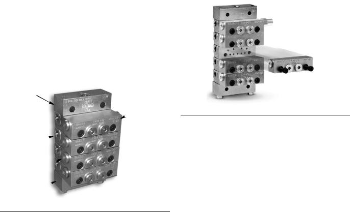
1.The MSP Divider Valves require assembly (FIG. 5).
NOTE: Refer to the MSP Divider Valve Assembly Table and MSP Divider Valve and Lube Points Assembly reference illustrations, FIG. 12 - FIG. 13 (page 16), to verify assembly orientation.
a.Remove components from packaging.
b.Assemble metering valves to base plates as shown in FIG. 5.
MSP Valve Component Identification
NOTE: The MSP Divider Valves shown in FIG. 4 - FIG. 10 are provided for reference only. The MSP Divider Valves used in your installation may include fewer or more blocks and appear slightly different than those shown in the reference figures.
B
A
FIG. 5
C
D
E
FIG. 4
Key:
AValve Section
BInlet Section
CIndicator / Port Plug
DEnd Plug
EEnd Section
14 |
NOTE: Photographs may include optional equipment. |
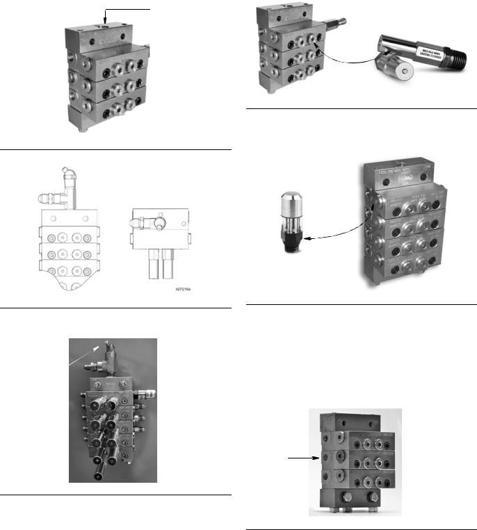
2.Install inlet fitting assembly in ports (FIG. 6).
•Inlet fitting assembly includes: a 1/4 inch tee, a 1/4 x 4 JIC and a zerk fitting
•Orient zerk fitting so it is always easily accessible (see FIG. 6 and FIG. 7).
FIG. 6
MSP Divider Valves
5.Install 1500 psi (10.34 bar, 103.4 MPa) performance indicators in ports (FIG. 9):
NOTE: Refer to the MSP Divider Valve Assembly (page 16) to verify assembly orientation.
Performance
Indicator
FIG. 9
6.Install cycle indicators in valves (FIG. 10).
• Magnetic Cycle indicators (quantity 2)
Cycle Indicator
FIG. 7
3. Install grease zerk fittings and zerk cover (FIG. 8).
zerk
FIG. 8
4.Remove end plugs and indicator port plugs before installing performance and cycle indicators in the MSP Divider Valve assembly.
FIG. 10
7.Install outlet plugs in all open ports as shown in the MSP Divider Valve Assembly reference illustrations (FIG. 12 and FIG. 13, page 16.
8.Install outlet fittings in all ports (FIG. 11).
•All outlets use 1/8 in. x 4 JIC straight fittings (included in kit).
Outlet
Port
FIG. 11
NOTE: Photographs may include optional equipment. |
15 |

MSP Divider Valves
MSP Divider Valve Assembly
Boom and Swing |
|
|
Arm and |
Circle Valve |
|
|
Bucket Valve |
(FIG. 12) |
|
|
(FIG. 13) |
|
|
Plug |
|
10T |
|
10S |
|
40T |
|
|
20T |
40T |
|
|
40T |
40T |
|
|
40T |
20S |
Plug |
|
40T |
MSP Divider Valve and Lube Points Assembly
Boom and Swing Circle Valve (FIG. 12)
FIG. 12
Arm and Bucket Valve (FIG. 13)
FIG. 13
16 |
NOTE: Photographs may include optional equipment. |
Loading...