


 Loading...
Operation & Maintenance |
WEAM006000 |
|
|
Manual |
|
|
|
|
|
|
|
|
|
WB93R-5
BACKHOE-LOADER
SERIAL NUMBER
WB93R-5 F50003 and up

 ATTENTION
Unsafe use of this machine may cause serious injury or death. Operators and maintenance personnel must read this manual before operating or maintaining this machine.
This manual should be kept inside the cab for reference and periodically reviewed by all personnel who will come into contact with the machine.

FOREWORD
1.1 FOREWORD
q This manual has been produced by Komatsu Utility S.p.A. in order to supply their customers with all the necessary information on the machine and the safety regulations related to it, together with the use and maintenance instructions that enable the operator to exploit the capacity of the machine with optimal results and to keep the machine efficient over time.
q The operation manual, together with the spare parts catalogue, is an integral part of the machine and must accompany it, even when it is resold, until its final disposal.
q The manual must be handled with the greatest care and always kept on board the machine, so that it can be consulted at any moment; it must be placed in the appropriate compartment behind the seat, where also the ownership documents and the logbook are usually kept (see "3.5.9 TECHNICAL DOCUMENTATION").
q This manual must be given to the persons who have to use the machine and carry out the routine maintenance operations; they must read the contents carefully more than once, in such a way as to clearly understand what are the correct operating conditions and the dangerous conditions that must be avoided.§
In case of loss or damage, request a new copy to Komatsu or your Komatsu Dealer.
qThe illustrations contained in this manual may represent machine configurations available on request.
The machines are constantly upgraded in order to increase their efficiency and reliability; this manual sums up all the information regarding the state of the art at the moment when the machine is launched on the market. Contact your Komatsu Dealer for updated information.
qPunctual periodic annotations regarding the maintenance operations that have been carried out are important to have a clear prospect of the situation and to know exactly what has been done and what has to be done after the next maintenance interval. Therefore, it is advisable to consult both the hour meter and the maintenance plan frequently.
q Komatsu Dealers have gathered a considerable amount of experience over years of work in close contact with the users.
If more information is needed, do not hesitate to contact your Komatsu Dealer: he always knows how to get the best performance from the machine, he can recommend the equipment that is most suitable for specific needs and can provide the technical assistance necessary for any change that may be required to conform the machine to the safety standards and traffic rules.
Komatsu Dealers also provide assistance for the supply of original Komatsu spare parts, which alone guarantee safety and interchangeability.
qThe table included in this manual must be filled in with the machine data, which are the data that must always be indicated to the Dealer when requiring assistance and ordering spare parts.
CAUTION
q The incorrect use of the machine and inappropriate maintenance operations may cause serious injury and even death.
qOperators and maintenance personnel must carefully read this manual before using the machine or performing maintenance operations.
q Some actions involved in the operation and maintenance of the machine may cause serious injury or even death, if they are not performed in compliance with the instructions given herein.
q The procedures and precautions described in this manual are valid for application to the machine only when it is used correctly.
If the machine is used for any purpose or in any way other than those described herein, the operator shall be responsible for his own safety and for the safety of any other person involved.
1

INFORMATION ON SAFETY
1.2 INFORMATION ON SAFETY
Many accidents are caused by insufficient knowledge of and failure to comply with the safety regulations prescribed for the maintenance operations that must be performed on the machine.
In order to avoid accidents, before starting work and before carrying out any maintenance operation, carefully read and be sure to understand all the information and warnings contained in this manual and given on the plates applied onto the machine.
To allow the operator to use the machine in total safety, precautions and safety plates are described in this manual and applied to the machine in order to supply information regarding situations that involve potential risks and the measures that may be adopted to avoid such situations.
Terminology used in the signs
The following terms are used in the signs to inform the user that there is a situation of potential danger that may cause injury or damage.
In this manual and in the plates applied to the machine the following terms are used to indicate potential dangers.
DANGER
q Indicates a situation of imminent danger that, if not avoided, may cause serious injury and even death.
The use of this term must be limited to situations of extreme danger.
WARNING
q Indicates a situation of potential danger that, if not avoided, may cause serious injury and even death.
CAUTION
q Indicates a situation of potential danger that, if not avoided, may cause moderate injury. This term can also be used as a warning in case of dangerous procedures.
Other terms used in the signs
In addition to those indicated above, the following warning terms are used to recommend the precautions to be taken to protect the machine or to supply useful information.
IMPORTANT
q This term is used to indicate precautions that must be taken in order to avoid actions that may reduce the life of the machine.
NOTE
q This word is used to indicate a useful piece of information.
Komatsu cannot reasonably predict every circumstance that might involve a potential hazard during the operation or maintenance of the machine; for this reason, the safety messages included in this manual and applied onto the machine may not include all possible safety precautions.
If all the procedures and operations prescribed for this machine are kept to, you can be sure that the operator and the persons in the vicinity will work in total safety, with no risk of damaging the machine. In case of doubt regarding the safety measures necessary for some procedures, contact Komatsu or your local Dealer.
2

INFORMATION ON SAFETY
DANGER
q Before starting any maintenance operation, position the machine on firm and level ground, engage the safety locks of the equipment and of the controls, stop the engine and apply the parking brake.
DANGER
q To make the information clearer, some illustrations in this manual represent the machine without safety guards. Do not use the machine without guards and do not start the engine when the hood is open, unless this is expressly prescribed for certain maintenance operations.
WARNING
q It is strictly forbidden to modify the setting of the hydraulic system safety valves; Komatsu cannot be held liable for any personal injury, or damage to property or the machine, if this has been tampered with by modifying the standard setting of the hydraulic system.
WARNING
q Before carrying out any electric welding operation, disconnect the battery and the alternator. (See
"2.8.13 PRECAUTIONS CONCERNING THE BATTERY AND THE ALTERNATOR").
WARNING
q Install only authorized additional equipment (See "6.1 AUTHORIZED OPTIONAL EQUIPMENT").
WARNING
q The machine can travel on roads only if equipped with suitable lighting, signalling and safety devices and if this type of use is authorized by the logbook.
Before travelling on roads, make sure that the equipment with which the machine is provided is homologated and that the safety locks are correctly engaged.
DANGER
qIt is absolutely forbidden to manoeuvre the machine while standing on the ground.
Each operation must be carried out by the operator correctly seated in the driving position.
3

INTRODUCTION
1.3 INTRODUCTION
1.3.1 INTENDED USES
The Komatsu BACKHOE LOADERS described in this manual have been designed and constructed to be used mainly with the following functions:
q LOADER
q EXCAVATOR
Through the installation of optional equipment, the machine can also be used for the following applications: q HANDLING OF MATERIALS (4IN1 BUCKET - PALLET FORKS)
q SNOWPLOUGH (ANGLEDOZER BLADE - SNOWPLOUGH)
q DEMOLITION (HAND HAMMER - HAMMER ON THE BACKHOE) q DITCH CLEANING AND DIGGING (SPECIAL BUCKETS)
1.3.2 IMPROPER OR UNAUTHORIZED USE
CAUTION
qThis paragraph describes some improper or unauthorized uses of the machine; since it is impossible to predict all possible improper uses, if the machine is going to be used for particular applications, contact your Komatsu Dealer before carrying out the work.
IMPORTANT
q The instructions regarding the authorized optional equipment are given in the relevant operation and maintenance manuals; if the equipment is supplied by Komatsu, these publications are enclosed to this manual.
qThe instructions regarding the assembly of the authorized equipment, the controls requiring special arrangements on the machine and the hydraulic couplings necessary for the operation of the equipment are grouped in the final section of this manual.
Komatsu BACKHOE LOADERS are constructed exclusively for the handling, excavation and treatment of inert materials; therefore, the following uses are absolutely forbidden:
q USE OF THE MACHINE BY MINORS OR INEXPERIENCED PERSONS. q USE OF THE MACHINE FOR LIFTING PERSONS OR OBJECTS.
q TRANSPORTATION OF PERSONS even if they are in the operator’s cab.
q TRANSPORTATION OF CONTAINERS with fluids, flammable fluids, loose material, without the appropriate slinging equipment.
q TRANSPORTATION AND LIFTING (EVEN IF IN EXCEPTIONAL CASES) OF EQUIPMENT OR MATERIALS THAT PROTRUDE FROM THE BUCKET OR ARE NOT SECURED TO THE BUCKET BY MEANS OF ROPES OR CHAINS.
q USE OF THE BUCKET FOR DRIVING OR EXTRACTING PILES.
q USE OF THE MACHINE FOR TOWING DAMAGED VEHICLES ON ROADS. q USE OF THE MACHINE FOR LIFTING DAMAGED VEHICLES.
4
INTRODUCTION
1.3.3 MAIN CHARACTERISTICS
q Simple and easy operation.
q Servo-assisted steering with priority hydraulic system.
q4-gear mechanical gearshift and transmission with hydraulic converter; reversal controlled by a lever positioned under the steering wheel.
q Loader control through a single servo lever ensuring also combined movements that can be modulated proportionally and continually.
qBackhoe controls through mechanical levers ensuring also combined movements that can be modulated proportionally and continually. On request, the backhoe can be controlled by means of two servo levers.
q Complete series of instruments visible from the two operating positions (loader or backhoe). q Separate accelerator controls for the two operating positions.
q Foot brake control.
q Easy maintenance with simplified intervals.
1.3.4 RUNNING-IN
Every machine is scrupulously adjusted and tested before delivery.
A new machine, however, must be used carefully for the first 100 hours, in order to ensure proper running-in of the various components.
If the machine is subjected to an excessive work load at the beginning of its service life, its productivity and functionality will be untimely reduced.
Every new machine must be used carefully, paying special attention to the following indications:
q After the start, let the engine idle for 5 minutes, in such a way as to warm it up gradually before actual operation. q Avoid operating the machine with the limit loads allowed or at high speed.
q Avoid abrupt starts or accelerations, useless sudden decelerations and abrupt reversals.
qAfter the first 250 hours of use, carry out the following operations, in addition to those to be performed every 250 hours:
1 - Change the hydraulic transmission oil and filter.
2 - Change the differential unit oil (front and rear axle).
3 - Change the final reduction gear oil (front and rear axle). 4 - Change the hydraulic circuit oil filter.
SYNTHETIC BIODEGRADABLE OIL TYPE HEES
On machines in which the synthetic biodegradable oil type HEES is used, the following operations are to be performed together with the standard maintenance operations.
q After the first 50 hours of operation, change the hydraulic circuit drain filter. q After the first 500 hours of operation, change the hydraulic circuit oil.
IMPORTANT
q When changing the oil filters (cartridges), check their innner part to make sure that there are no deposits. If abundant deposits are observed, find out what may have caused their accumulation before starting the machine.
q The number of operation hours is indicated by the hour meter.
5
PRODUCT IDENTIFICATION
1.4 PRODUCT IDENTIFICATION
The Komatsu backhoe loader and its main components are identified by serial numbers stamped on the identification plates. The serial number and the identification numbers of the components are the only numbers that must be indicated to the Dealer when requiring assistance and ordering spare parts.
1.4.1MACHINE IDENTIFICATION NUMBER (PIN)
The machine identification number "PIN" is stamped on the right side of the frame front.
RKAB2670
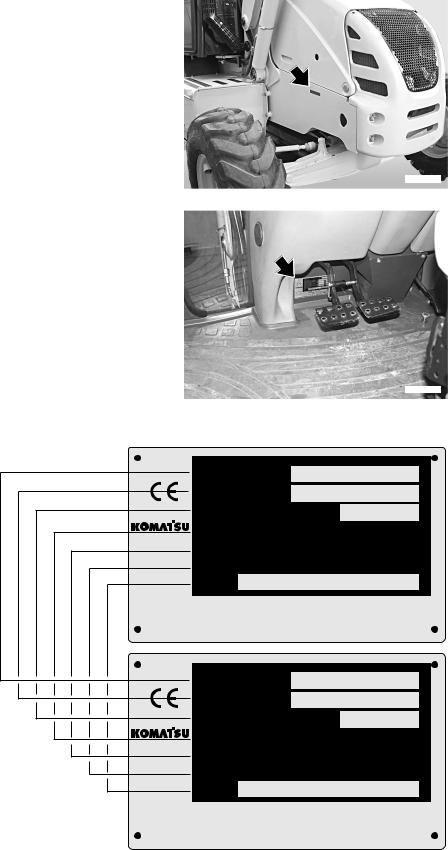
1.4.2MACHINE IDENTIFICATION PLATE AND PRODUCT IDENTIFICATION NUMBER (PIN)
(alternatively for some markets)
The Komatsu BACKHOE LOADERS described in this manual are CE marked, in fact they are in full compliance with the EU harmonised standards. The Product Identification Number (PIN) is stamped on the lower part of the plate. The customer must be able to indicate the PIN at any time, that is why it must
compulsorily be written in the following table. The plate with RKAB2680 the CE marking is applied inside the cab, on the left vertical
wall of the frame, at the height of the brake pedals.
MODELLO - MODEL
TYP - MODELE
MATRICOLA N˚ - SERIAL N˚
FABR. NR. - SERIE NR.
ANNO - YEAR
BAUJAHR - ANNEE
MASSA TOTALE - TOTAL WEIGHT
GESAMTGEWICHT - POIDS TOTAL
POTENZA MOTORE - ENGINE POWER
LEISTUNG - PUISSANCE MOTEUR
Product Identification Number
PIN
MANUFACTURED BY KOMATSU UTILITY EUROPE S.p.A.
36025 NOVENTA VICENTINA (VI) - ITALY
MODEL
SERIAL N˚
YEAR
TOTAL WEIGHT
ENGINE POWER
Product Identification Number
PIN
 kg
kg  kw
kw
37A-98-11820
37A-98-11820
RKA14970
 kg
kg  kw
kw
MANUFACTURED BY KOMATSU UTILITY EUROPE S.p.A.
36025 NOVENTA VICENTINA (VI) - ITALY
6
PRODUCT IDENTIFICATION
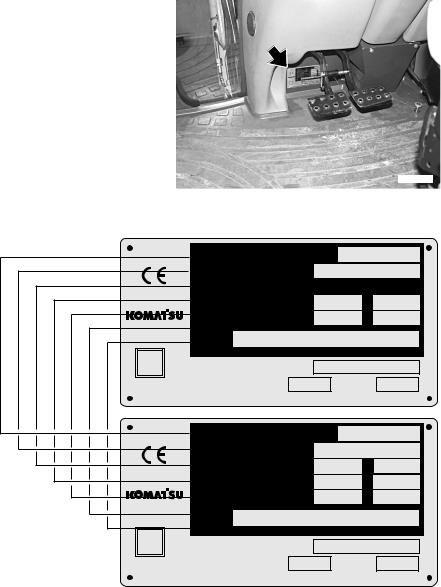
1.4.3MACHINE IDENTIFICATION PLATE AND PRODUCT IDENTIFICATION NUMBER (PIN)
The Komatsu BACKHOE LOADERS described in this manual are CE marked, in fact they are in full compliance with the EU harmonised standards.
The Product Identification Number (PIN) is stamped on the lower part of the plate. The customer must be able to indicate the PIN at any time, that is why it must compulsorily be written in the following table. The plate with the CE marking is applied
inside the cab, on the left vertical wall of the frame, at the RKAB2680 height of the brake pedals.
TIPO
TYPE - MODEL
NUMERO DI OMOLOGAZIONE
HOMOLOGATION NUMBER
MASSA TOTALE AMMISSIBILE |
DA |
kg |
A |
kg |
TOTAL MASS WEIGHT |
FROM |
TO |
CARICO AMMISSIBILE ASSE ANT. |
DA |
kg |
A |
kg |
WEIGHT FRONT AXLE |
FROM |
|
TO |
|
CARICO AMMISSIBILE ASSE POST. |
DA |
kg |
A |
kg |
WEIGHT REAR AXLE |
FROM |
|
TO |
|
Product Identification Number |
|
|
|
|
PIN |
|
|
|
|
- Massa rimorchiabile: non atto |
|
|
|
|
MATRICOLA |
|
|
|
|
SERIAL NUMBER |
|
|
|
|
POTENZA MOTORE |
kW |
ANNO |
|
|
MANUFACTURED BY KOMATSU UTILITY EUROPE S.p.A. 36025 NOVENTA VIC. (VI) -ITALY |
37A-98-11840 |
|||
|
|
|
|
RKA16060 |
TYPE |
|
|
|
|
HOMOLOGATION NUMBER |
|
|
|
|
TOTAL MASS WEIGHT |
FROM |
kg TO |
kg |
|
WEIGHT FRONT AXLE |
FROM |
kg TO |
kg |
|
WEIGHT REAR AXLE |
FROM |
kg TO |
kg |
|
Product Identification Number |
|
|
|
|
PIN |
|
|
|
|
- Towable weight: not suitable |
|
|
|
|
SERIAL NUMBER |
|
|
|
|
ENGINE POWER |
kW |
YEAR |
|
|
MANUFACTURED BY KOMATSU UTILITY EUROPE S.p.A. 36025 NOVENTA VIC. (VI) -ITALY |
37A-98-11840 |
|||
7
PRODUCT IDENTIFICATION
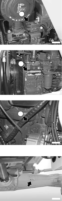
1.4.4ENGINE SERIAL NUMBER AND EXHAUST GAS EMISSION PLATE
The identification plate (1) is fixed above the engine head and indicates the engine model, total displacement and serial number.
The identification plate (2) is fixed to the left side of the engine block, bears the Manufacturer’s mark and contains the following data:
1 - Engine type
2 - Engine family
3 - Serial number
4 - EC Type Approval
5 - EPA
The serial number (3) is also stamped on the right side of the cylinder block, on the upper part of the oil cooling heat exchanger.
1.4.5 FRONT AXLE SERIAL NUMBER
The serial number of the front axle is stamped on the plate positioned on the right side of the axle body.
1
RKAB2690
2
RKAB2700
3
RKAB2710
RKAB2720
8
PRODUCT IDENTIFICATION
1.4.6 REAR AXLE SERIAL NUMBER
The serial number of the rear axle is stamped on the plate positioned on the right side of the axle body.
RKAB2730
1.4.7 TRANSMISSION SERIAL NUMBER
The transmission serial number is stamped on the plate postioned on the right side of the transmission case.
RKAB2750
1.4.8 CAB SERIAL NUMBER
The cab serial number is stamped on the plate postioned on the left side of the rear wall.
RKAB2740
9

PRODUCT IDENTIFICATION
1.4.9 SERIAL NUMBERS AND DEALER’S ADDRESS
Machine no. |
|
|
|
|
|
Mod. |
|
|||
Product identification number (PIN) |
|
|
|
|
||||||
|
|
|
|
|||||||
Engine no. |
|
|
|
|
||||||
|
|
|
|
|||||||
Front axle no. |
|
|
|
|
|
|||||
Rear axle no. |
|
|
|
|
|
|||||
Transmission no. |
|
|
|
|
||||||
Cab no. |
|
|
|
|
|
|||||
|
|
|
|
|
|
|
|
|
|
|
|
|
|
|
|
|
|
|
|
|
|
Dealer:
Address:
Tel.
Contact person:
NOTES:
10
TABLE OF CONTENTS
TABLE OF CONTENTS
FOREWORD
1.1 |
FOREWORD.......................................................................................................................................... |
1 |
|
1.2 |
INFORMATION ON SAFETY................................................................................................................ |
2 |
|
1.3 |
INTRODUCTION ................................................................................................................................... |
4 |
|
|
1.3.1 |
INTENDED USES .................................................................................................................... |
4 |
|
1.3.2 |
IMPROPER OR UNAUTHORIZED USE .................................................................................. |
4 |
|
1.3.3 |
MAIN CHARACTERISTICS...................................................................................................... |
5 |
|
1.3.4 |
RUNNING-IN ............................................................................................................................ |
5 |
1.4 |
PRODUCT IDENTIFICATION ............................................................................................................... |
6 |
|
|
1.4.1 |
MACHINE IDENTIFICATION NUMBER (PIN) ......................................................................... |
6 |
|
1.4.2 |
MACHINE IDENTIFICATION PLATE AND PRODUCT IDENTIFICATION NUMBER |
|
|
|
(PIN) (alternatively for some markets) ..................................................................................... |
6 |
|
1.4.3 |
MACHINE IDENTIFICATION PLATE AND PRODUCT IDENTIFICATION NUMBER (PIN) .... |
7 |
|
1.4.4 |
ENGINE SERIAL NUMBER AND EXHAUST GAS EMISSION PLATE ................................... |
8 |
|
1.4.5 |
FRONT AXLE SERIAL NUMBER............................................................................................. |
8 |
|
1.4.6 |
REAR AXLE SERIAL NUMBER ............................................................................................... |
9 |
|
1.4.7 |
TRANSMISSION SERIAL NUMBER........................................................................................ |
9 |
|
1.4.8 |
CAB SERIAL NUMBER............................................................................................................ |
9 |
|
1.4.9 |
SERIAL NUMBERS AND DEALER’S ADDRESS .................................................................... |
10 |
|
TABLE OF CONTENTS ........................................................................................................................ |
11 |
|
SAFETY AND ACCIDENT PREVENTION |
|
||
2.1 SAFETY, NOISE AND VIBRATION PLATES....................................................................................... |
20 |
||
|
2.1.1 |
POSITION OF THE SAFETY PLATES .................................................................................... |
20 |
|
2.1.2 |
PICTOGRAMS AND RELEVANT MEANINGS......................................................................... |
22 |
|
2.1.3 |
POSITION OF THE NOISE PLATES ON MACHINES WITH CAB .......................................... |
28 |
|
2.1.4 |
VIBRATIONS TO WHICH THE OPERATOR IS SUBJECTED ................................................ |
29 |
2.2 |
GENERAL PRECAUTIONS .................................................................................................................. |
30 |
|
|
2.2.1 |
GENERAL SAFETY RULES .................................................................................................... |
30 |
|
2.2.2 |
SAFETY DEVICES AND GUARDS.......................................................................................... |
30 |
|
2.2.3 |
CLOTHING AND PERSONAL PROTECTION ITEMS ............................................................. |
30 |
|
2.2.4 |
UNAUTHORIZED MODIFICATIONS ....................................................................................... |
30 |
|
2.2.5 |
LEAVING THE OPERATOR’S SEAT ....................................................................................... |
31 |
|
2.2.6 |
GETTING ON AND OFF THE MACHINE................................................................................. |
32 |
|
2.2.7 |
CHECKING THE REAR-VIEW MIRRORS .............................................................................. |
32 |
|
2.2.8 |
PREVENTING FIRES DUE TO FUEL AND OIL ..................................................................... |
33 |
|
2.2.9 |
PREVENTING BURNS ............................................................................................................ |
33 |
|
2.2.10 |
PREVENTING DAMAGE DUE TO ASBESTOS POWDER .................................................... |
34 |
|
2.2.11 |
PREVENTING DAMAGE CAUSED BY THE WORK EQUIPMENT ........................................ |
34 |
|
2.2.12 |
FIRE EXTINGUISHERS AND FIRST AID KIT ........................................................................ |
35 |
|
2.2.13 |
PRECAUTIONS CONCERNING THE CAB STRUCTURE ...................................................... |
35 |
|
2.2.14 |
PRECAUTIONS CONCERNING THE EQUIPMENT ............................................................... |
35 |
2.3 PRECAUTIONS TO BE TAKEN BEFORE STARTING THE ENGINE ................................................. |
36 |
||
|
2.3.1 |
SAFETY ON THE WORK SITE ............................................................................................... |
36 |
|
2.3.2 |
FIRE PREVENTION ................................................................................................................ |
36 |
|
2.3.3 |
PRECAUTIONS TO BE TAKEN FOR THE OPERATOR'S CAB ............................................. |
36 |
|
2.3.4 |
ROOM VENTILATION ............................................................................................................. |
37 |
|
2.3.5 |
CLEANING WINDOWS, MIRRORS AND LIGHTS - CHECKING THE WINDSHIELD |
|
|
|
WIPER BLADES AND THE BULBS ......................................................................................... |
37 |
11
TABLE OF CONTENTS |
|
|
2.4 PRECAUTIONS TO BE TAKEN DURING WORK................................................................................ |
38 |
|
2.4.1 |
WHEN STARTING THE ENGINE............................................................................................. |
38 |
2.4.2 |
RULES FOR TRAVELLING ON ROADS.................................................................................. |
38 |
2.4.3 |
HAND SIGNALS ....................................................................................................................... |
39 |
2.4.4 |
CHECKS FOR TRAVELLING IN REVERSE ............................................................................ |
44 |
2.4.5 |
MOVING THE MACHINE ......................................................................................................... |
44 |
2.4.6 |
WORKING ON SLOPES ......................................................................................................... |
45 |
2.4.7 |
PREVENTING ELECTROCUTION .......................................................................................... |
46 |
2.4.8 |
VISIBILITY ................................................................................................................................ |
47 |
2.4.9 |
WORKING ON ICY OR SNOW-COVERED SURFACES......................................................... |
47 |
2.4.10 |
PREVENTING DAMAGE CAUSED BY THE WORK EQUIPMENT ......................................... |
47 |
2.4.11 |
WORKING ON LOOSE GROUND ........................................................................................... |
47 |
2.4.12 |
PARKING THE MACHINE........................................................................................................ |
48 |
2.5 TRANSPORTING THE MACHINE ON OTHER VEHICLES ................................................................. |
49 |
|
2.5.1 |
LOADING AND UNLOADING THE MACHINE ........................................................................ |
49 |
2.5.2 |
TRANSPORT............................................................................................................................ |
49 |
2.6 BATTERY .............................................................................................................................................. |
50 |
|
2.6.1 |
PREVENTING RISKS THAT MAY BE DUE TO THE BATTERY ............................................. |
50 |
2.6.2 |
STARTING WITH BOOSTER CABLES ................................................................................... |
50 |
2.7 PRECAUTIONS FOR EMERGENCY RECOVERY............................................................................... |
51 |
|
2.8 PRECAUTIONS TO BE TAKEN DURING MAINTENANCE................................................................. |
52 |
|
2.8.1 |
WARNING PLATES.................................................................................................................. |
52 |
2.8.2 |
TOOLS ..................................................................................................................................... |
52 |
2.8.3 |
PERSONNEL............................................................................................................................ |
53 |
2.8.4 |
EQUIPMENT ........................................................................................................................... |
53 |
2.8.5 |
WORKING UNDER THE MACHINE ........................................................................................ |
53 |
2.8.6 |
KEEPING THE MACHINE CLEAN .......................................................................................... |
54 |
2.8.7 |
USE OF THE ENGINE DURING MAINTENANCE ................................................................... |
54 |
2.8.8 |
PERIODICAL CHANGE OF THE SAFETY RELATED PARTS................................................ |
54 |
2.8.9 |
STOP THE ENGINE BEFORE CARRYING OUT ANY MAINTENANCE OPERATION |
|
|
OR INSPECTION .................................................................................................................... |
55 |
2.8.10 |
RULES TO BE FOLLOWED DURING FUEL OR OIL TOPPING UP ...................................... |
56 |
2.8.11 |
CHECKING THE COOLANT LEVEL IN THE RADIATOR........................................................ |
56 |
2.8.12 |
USING LAMPS ......................................................................................................................... |
56 |
2.8.13 |
PRECAUTIONS CONCERNING THE BATTERY AND THE ALTERNATOR .......................... |
57 |
2.8.14 |
PRECAUTIONS CONCERNING THE STARTER .................................................................... |
57 |
2.8.15 |
HANDLING HIGH-PRESSURE PIPES..................................................................................... |
58 |
2.8.16 PRECAUTIONS TO BE TAKEN WHEN WORKING ON HIGHPRESSURE SYSTEMS ....... |
58 |
|
2.8.17 PRECAUTIONS FOR MAINTENANCE WORK INVOLVING HIGH TEMPERATURES |
|
|
|
AND PRESSURES ................................................................................................................... |
58 |
2.8.18 |
HYDRAULIC ACCUMULATOR ................................................................................................ |
59 |
2.8.19 |
COOLING FAN AND FAN BELT .............................................................................................. |
59 |
2.8.20 |
WASTE MATERIALS................................................................................................................ |
59 |
2.8.21 |
PRECAUTIONS CONCERNING TECHNOPOLYMERS AND ELASTOMERS........................ |
60 |
2.8.22 |
PRECAUTIONS TO BE TAKEN WHEN INFLATING THE TYRES ......................................... |
60 |
2.8.23 PRECAUTIONS FOR THE INSTALLATION OF THE EXHAUST SYSTEM TAILPIPE............ |
61 |
|
2.8.24 PRECAUTIONS TO BE TAKEN WHEN USING SYNTHETIC BIODEGRADABLE |
|
|
|
OIL TYPE «HEES»................................................................................................................... |
61 |
12
|
|
|
TABLE OF CONTENTS |
|
DESCRIPTION AND USE OF THE MACHINE |
|
|||
3.1 |
SAFETY LOCKS ................................................................................................................................... |
|
64 |
|
|
3.1.1 |
FRONT LOADER LOCKS ........................................................................................................ |
64 |
|
|
3.1.2 |
BACKHOE LOCKS................................................................................................................... |
66 |
|
3.2 |
GENERAL VIEWS................................................................................................................................. |
|
68 |
|
|
3.2.1 |
FRONT GENERAL VIEW......................................................................................................... |
68 |
|
|
3.2.2 |
BACKHOE GENERAL VIEW.................................................................................................... |
69 |
|
|
3.2.3 |
CAB INSIDE GENERAL VIEW................................................................................................. |
70 |
|
|
|
3.2.3.1 CAB INSIDE GENERAL VIEW (mechanical backhoe controls).............................. |
70 |
|
|
|
3.2.3.2 CAB INSIDE GENERAL VIEW (backhoe servo controls) ....................................... |
71 |
|
3.3 |
INSTRUMENTS AND CONTROLS ....................................................................................................... |
72 |
||
|
3.3.1 |
FRONT INSTRUMENTS .......................................................................................................... |
72 |
|
|
3.3.2 |
SIDE INSTRUMENTS .............................................................................................................. |
76 |
|
|
3.3.3 PUSH BUTTONS ON THE FRONT LOADER CONTROL LEVER .......................................... |
84 |
||
|
3.3.4 |
PUSH BUTTON ON THE GEARSHIFT LEVER....................................................................... |
85 |
|
|
3.3.5 |
CAB SWITCHES AND ELECTRIC ACCESSORIES................................................................ |
86 |
|
|
3.3.6 |
MACHINE CONTROLS ............................................................................................................ |
89 |
|
|
|
3.3.6.1 MACHINE CONTROLS (version with mechanically-controlled backhoe) .............. |
89 |
|
|
|
3.3.6.2 MACHINE CONTROLS (version with servo-assisted backhoe) ............................. |
91 |
|
|
|
3.3.6.3 |
ADJUSTING THE CONTROLS .............................................................................. |
111 |
3.4 |
FUSES AND RELAYS........................................................................................................................... |
114 |
||
|
3.4.1 CENTRAL UNIT FUSES – RELAYS AND ENGINE LINE........................................................ |
114 |
||
|
|
3.4.1.1 |
FUSES ................................................................................................................... |
114 |
|
|
3.4.1.2 |
RELAYS .................................................................................................................. |
116 |
|
3.4.2 |
VENTILATION, HEATING AND AIR CONDITIONING FUSES AND RELAYS ........................ |
117 |
|
|
|
3.4.2.1 |
FUSES ................................................................................................................... |
117 |
|
|
3.4.2.2 |
RELAYS ................................................................................................................. |
117 |
3.5 GUARDS, CAB AND DRIVER’S SEAT ................................................................................................ |
118 |
|||
|
3.5.1 |
ENGINE HOOD ........................................................................................................................ |
118 |
|
|
3.5.2 |
CAB .......................................................................................................................................... |
|
119 |
|
3.5.3 |
VENTILATION AND HEATING ................................................................................................ |
122 |
|
|
3.5.4 |
AIR CONDITIONER (if installed) .............................................................................................. |
123 |
|
|
3.5.5 |
SEAT ........................................................................................................................................ |
|
125 |
|
|
3.5.5.1 |
SEAT (STANDARD) ............................................................................................... |
125 |
|
|
3.5.5.2 |
SEAT (OPTIONAL) ................................................................................................ |
126 |
|
3.5.6 |
SAFETY BELT.......................................................................................................................... |
127 |
|
|
3.5.7 |
FIRE EXTINGUISHER ............................................................................................................ |
127 |
|
|
3.5.8 |
FIRST AID KIT ......................................................................................................................... |
127 |
|
|
3.5.9 |
TECHNICAL DOCUMENTATION ........................................................................................... |
127 |
|
|
3.5.10 |
STORAGE COMPARTMENT .................................................................................................. |
128 |
|
3.6 USE OF THE MACHINE........................................................................................................................ |
129 |
|||
|
3.6.1 |
CHECKS TO BE CARRIED OUT BEFORE STARTING THE ENGINE ................................... |
129 |
|
|
|
3.6.1.1 |
VISUAL CHECKS.................................................................................................... |
129 |
|
|
3.6.1.2 |
OPERATIONAL CHECKS ...................................................................................... |
130 |
|
3.6.2 |
STARTING THE ENGINE ........................................................................................................ |
131 |
|
|
|
3.6.2.1 STARTING WITH WARM ENGINE OR IN TEMPERATE CLIMATES ................... |
131 |
|
|
|
3.6.2.2 STARTING WITH COLD ENGINE OR IN COLD CLIMATES ................................ |
132 |
|
|
3.6.3 |
WARMING THE ENGINE......................................................................................................... |
133 |
|
|
3.6.4 |
HEATING THE HYDRAULIC OIL............................................................................................. |
133 |
|
|
3.6.5 |
HOW TO MOVE THE MACHINE ............................................................................................. |
134 |
|
|
|
3.6.5.1 |
DIFFERENTIAL LOCKING...................................................................................... |
135 |
|
|
3.6.5.2 ENGAGING THE FOUR-WHEEL DRIVE ............................................................... |
135 |
|
13
TABLE OF CONTENTS |
|
|
||
|
|
3.6.5.3 |
WORKING ON SLOPES ........................................................................................ |
136 |
|
|
3.6.5.4 |
MAXIMUM IMMERSION DEPTH ............................................................................ |
137 |
3.7 |
PARKING THE MACHINE .................................................................................................................... |
138 |
||
|
3.7.1 PARKING ON LEVEL GROUND .............................................................................................. |
138 |
||
|
3.7.2 |
PARKING ON SLOPES............................................................................................................ |
139 |
|
3.8 |
STOPPING THE ENGINE ..................................................................................................................... |
140 |
||
3.9 |
TRANSPORTING THE MACHINE ON OTHER VEHICLES ................................................................. |
141 |
||
|
3.9.1 |
LOADING AND UNLOADING THE MACHINE......................................................................... |
141 |
|
|
3.9.2 |
TRANSPORT............................................................................................................................ |
142 |
|
3.10 |
PRECAUTIONS TO BE TAKEN IN THE COLD SEASON ................................................................... |
143 |
||
|
3.10.1 |
FUEL AND LUBRICANTS ........................................................................................................ |
143 |
|
|
3.10.2 |
COOLANT |
................................................................................................................................ |
143 |
|
3.10.3 |
BATTERY ................................................................................................................................. |
|
144 |
|
3.10.4 |
OTHER PRECAUTIONS .......................................................................................................... |
144 |
|
|
3.10.5 |
PRECAUTIONS TO BE TAKEN AT THE END OF WORK ...................................................... |
144 |
|
3.11 |
PRECAUTIONS TO BE TAKEN AT THE END OF THE WINTER........................................................ |
145 |
||
3.12 |
USING THE MACHINE AS A LOADER................................................................................................ |
146 |
||
|
3.12.1 |
BUCKET POSITION INDICATOR ............................................................................................ |
146 |
|
|
3.12.2 |
ORGANIZING THE WORK AREA............................................................................................ |
146 |
|
|
|
3.12.2.1 LOADING HEAPED AND LEVEL MATERIAL ........................................................ |
147 |
|
|
|
3.12.2.2 LOADING OPERATIONS ON SLOPES.................................................................. |
148 |
|
|
3.12.3 |
CHANGING THE STANDARD FRONT BUCKET ................................................................... |
148 |
|
3.13 |
USING THE MACHINE AS AN EXCAVATOR...................................................................................... |
149 |
||
|
3.13.1 |
POSITIONING THE BUCKET ACCORDING TO THE WORK THAT MUST |
|
|
|
|
BE CARRIED OUT .................................................................................................................. |
149 |
|
|
3.13.2 |
POSITIONING THE MACHINE FOR DIGGING OPERATIONS............................................... |
150 |
|
|
3.13.3 |
SLIDING THE BACKHOE UNIT SIDEWARDS ........................................................................ |
151 |
|
|
3.13.4 |
DIGGING METHOD.................................................................................................................. |
152 |
|
|
|
3.13.4.1 CHANGING THE BACKHOE BUCKET................................................................... |
153 |
|
3.14 |
LONG PERIODS OF INACTIVITY ........................................................................................................ |
154 |
||
|
3.14.1 |
PREPARING THE MACHINE FOR A LONG PERIOD OF INACTIVITY .................................. |
154 |
|
|
3.14.2 |
PREPARING THE ENGINE FOR A LONG PERIOD OF INACTIVITY..................................... |
156 |
|
|
3.14.3 |
MAINTENANCE DURING A PERIOD OF INACTIVITY ........................................................... |
156 |
|
|
3.14.4 |
RESTARTING THE ENGINE.................................................................................................... |
157 |
|
|
3.14.5 |
AFTER THE PERIOD OF INACTIVITY .................................................................................... |
157 |
|
3.15 |
TROUBLESHOOTING .......................................................................................................................... |
158 |
||
|
3.15.1 |
HOW TO REMOVE THE MACHINE......................................................................................... |
158 |
|
|
3.15.2 |
AFTER THE FUEL HAS RUN OUT.......................................................................................... |
158 |
|
|
3.15.3 |
IF THE BATTERY HAS RUN DOWN ....................................................................................... |
159 |
|
|
|
3.15.3.1 STARTING WITH BOOSTER CABLES .................................................................. |
160 |
|
|
3.15.4 |
OTHER TROUBLES................................................................................................................. |
161 |
|
|
|
3.15.4.1 |
ELECTRICAL CIRCUIT........................................................................................... |
161 |
|
|
3.15.4.2 |
HYDRAULIC SYSTEM............................................................................................ |
161 |
|
|
3.15.4.3 |
BRAKING SYSTEM ................................................................................................ |
162 |
|
|
3.15.4.4 |
CONVERTER.......................................................................................................... |
162 |
|
|
3.15.4.5 |
ENGINE................................................................................................................... |
162 |
14
|
|
|
TABLE OF CONTENTS |
|
MAINTENANCE |
|
|
||
4.1 |
GUIDE TO MAINTENANCE.................................................................................................................. |
166 |
||
4.2 |
MAINTENANCE NOTES....................................................................................................................... |
168 |
||
|
4.2.1 NOTES REGARDING THE ENGINE ....................................................................................... |
168 |
||
|
|
4.2.1.1 |
ENGINE OIL ............................................................................................................ |
168 |
|
|
4.2.1.2 |
COOLANT ............................................................................................................... |
168 |
|
|
4.2.1.3 |
FUEL ....................................................................................................................... |
169 |
|
4.2.2 NOTES REGARDING THE HYDRAULIC SYSTEM................................................................. |
169 |
||
|
4.2.3 NOTES REGARDING THE ELECTRIC SYSTEM.................................................................... |
170 |
||
|
4.2.4 |
NOTES REGARDING LUBRICATION ..................................................................................... |
170 |
|
|
4.2.5 PARTS SUBJECT TO WEAR THAT PERIODICALLY NEED CHANGING.............................. |
171 |
||
4.3 FUEL, COOLANT AND LUBRICANTS ................................................................................................ |
172 |
|||
|
4.3.1 |
LUBRICATION WITH GREASE ............................................................................................... |
173 |
|
|
4.3.2 HOMOLOGATED SYNTHETIC BIODEGRADABLE LUBRICANTS “HEES” ........................... |
174 |
||
4.4 |
DRIVING TORQUES ............................................................................................................................. |
175 |
||
|
4.4.1 STANDARD DRIVING TORQUES FOR SCREWS AND NUTS .............................................. |
175 |
||
|
4.4.2 SPECIFIC DRIVING TORQUES FOR SCREWS AND NUTS ................................................. |
176 |
||
|
4.4.3 STANDARD DRIVING TORQUES FOR HOSES WITH ORFS................................................ |
176 |
||
4.5 |
LUBRICATION |
...................................................................................................................................... |
177 |
|
|
4.5.1 |
LUBRICATION ........................................................................................................DIAGRAM |
177 |
|
|
4.5.2 LUBRICATION ........................................................DIAGRAM (4in1 bucket and pallet forks) |
178 |
||
|
4.5.3 LUBRICATION ........................................................DIAGRAM (front bucket quick couplings) |
179 |
||
|
4.5.4 LUBRICATION ................................................................................DIAGRAM (offset device) |
180 |
||
4.6 PERIODICAL CHANGE ..............................................OF THE SAFETY RELATED COMPONENTS |
181 |
|||
|
4.6.1 |
SAFETY .....................................................................................................RELATED PARTS |
182 |
|
|
|
4.6.1.1 ...................................................................................................... |
FUEL SYSTEM |
182 |
|
|
4.6.1.2 ........................................................................ |
DELIVERY HYDRAULIC SYSTEM |
183 |
|
|
4.6.1.3 ...............................................................FRONT LOADER HYDRAULIC SYSTEM |
184 |
|
|
|
4.6.1.4 ............................................................................ |
BACKHOE HYDRALIC SYSTEM |
185 |
|
|
4.6.1.5 ......................................................................................... |
OPERATOR’S SAFETY |
186 |
4.7 |
MAINTENANCE ..........................................................................................................................PLAN |
187 |
||
4.8 |
MAINTENANCE ..........................................................................................................PROCEDURES |
189 |
||
|
4.8.1 |
WHEN ...................................................................................................................REQUIRED |
189 |
|
|
|
4.8.1.a ................ |
CHECKING, CLEANING OR CHANGING THE ENGINE AIR FILTERS |
189 |
|
|
4.8.1.b ............................................CHECKING AND CLEANING THE CAB AIR FILTER |
190 |
|
|
|
4.8.1.c CHECKING AND CLEANING THE AIR RECIRCULATION FILTER |
|
|
|
|
................................................................... |
(only for machines with air conditioner) |
191 |
|
|
4.8.1.d CHECKING THE DETERGENT LEVEL IN THE WINDSHIELD WASHER |
|
|
|
|
........................................................................................................... |
RESERVOIR |
191 |
|
|
4.8.1.e ..................................................CHECKING THE WINDSHIELD WIPER BLADES |
192 |
|
|
|
4.8.1.f .............................................................LUBRICATING THE CAB DOOR HINGES |
192 |
|
|
|
4.8.1.g ...................................................FUSES AND RELAYS – CHECK AND CHANGE |
192 |
|
|
|
4.8.1.h .....................................................................BLEEDING THE BRAKING CIRCUIT |
193 |
|
|
|
4.8.1.i .............................. |
CHECKING AND ADJUSTING THE FRONT WHEEL TOE - IN |
194 |
|
|
4.8.1.j .............................................................. |
CHECKING THE BRAKING EFFICIENCY |
194 |
|
|
4.8.1.k .........................................CHECKING AND ADJUSTING THE PARKING BRAKE |
195 |
|
|
|
4.8.1.l ............................. |
CHECKING AND ADJUSTING THE BRAKE PEDAL STROKE |
196 |
|
|
4.8.1.m ADJUSTING THE AUTOMATIC RETURN-TO-DIG DEVICE OF THE |
|
|
|
|
................................................................................. |
FRONT BUCKET (if installed) |
196 |
|
|
4.8.1.n ....................................CHECKING AND ADJUSTING THE STABILIZER SLACK |
197 |
|
|
4.8.2 MAINTENANCE ..............INTERVALS IN CASE OF USE OF THE DEMOLITION HAMMER |
198 |
||
|
|
4.8.2.a ...........................................................CHANGING THE HYDRAULIC OIL FILTER |
198 |
|
15
TABLE OF CONTENTS |
|
|
|
|
4.8.2.b |
CHANGING THE HYDRAULIC OIL ........................................................................ |
198 |
4.8.3 |
CHECKS TO BE CARRIED OUT BEFORE STARTING THE ENGINE ................................... |
199 |
|
|
4.8.3.a |
VARIOUS CHECKS ................................................................................................ |
199 |
|
4.8.3.b |
CHECKING THE COOLANT LEVEL....................................................................... |
199 |
|
4.8.3.c |
CHECKING THE FUEL LEVEL............................................................................... |
200 |
|
4.8.3.d |
CHECKING THE ENGINE OIL LEVEL ................................................................... |
200 |
4.8.4 MAINTENANCE EVERY 10 HOURS OF OPERATION ........................................................... |
201 |
||
|
4.8.4.a |
LUBRICATING THE JOINTS .................................................................................. |
201 |
4.8.5 MAINTENANCE AFTER THE FIRST 50 HOURS OF OPERATION |
|
||
|
(Only for machines in which synthetic biodegradable oil type HEES is used).......................... |
203 |
|
4.8.6 MAINTENANCE EVERY 50 HOURS OF OPERATION ........................................................... |
203 |
||
|
4.8.6.a |
CHECKING THE HYDRAULIC OIL LEVEL ............................................................ |
203 |
|
4.8.6.b |
CHECKING THE FLUID LEVEL IN THE RADIATOR ............................................. |
204 |
|
4.8.6.c CHECKING THE BRAKING SYSTEM OIL LEVEL ................................................. |
204 |
|
|
4.8.6.d |
LUBRICATING THE PROPELLER SHAFTS .......................................................... |
205 |
|
4.8.6.e |
LUBRICATING THE FRONT AXLE JOINTS AND CENTRAL COUPLING ............ |
206 |
|
4.8.6.f |
CHECKING THE TYRE PRESSURE ..................................................................... |
206 |
|
4.8.6.g |
DRAINING THE WATER SEPARATOR ................................................................. |
207 |
4.8.7 |
MAINTENANCE AFTER THE FIRST 250 HOURS OF OPERATION ...................................... |
208 |
|
4.8.8 MAINTENANCE EVERY 250 HOURS OF OPERATION ......................................................... |
208 |
||
|
4.8.8.a |
CHECKING THE ALTERNATOR-FAN BELT.......................................................... |
208 |
|
4.8.8.b CHECKING AND ADJUSTING THE A/C COMPRESSOR BELT TENSION |
|
|
|
|
(only for machines with air conditioner)................................................................... |
209 |
|
4.8.8.c |
CHECKING THE BATTERY ELECTROLYTE LEVEL ............................................ |
210 |
|
4.8.8.d |
CHECKING THE FRONT AXLE OIL LEVELS ........................................................ |
211 |
|
4.8.8.e |
CHECKING THE REAR AXLE OIL LEVEL ............................................................. |
211 |
|
4.8.8.f |
CHECKING THE HYDRAULIC TRANSMISSION OIL LEVEL ............................... |
212 |
|
4.8.8.g |
CHECKING THE WHEEL NUT DRIVING TORQUE............................................... |
212 |
4.8.9 MAINTENANCE AFTER THE FIRST 500 HOURS OF OPERATION |
|
||
|
(Only for machines in which synthetic biodegradable oil type HEES is used).......................... |
213 |
|
4.8.10 MAINTENANCE EVERY 500 HOURS OF OPERATION ......................................................... |
213 |
||
|
4.8.10.a |
CHANGING THE ENGINE OIL ............................................................................... |
213 |
|
4.8.10.b |
CHANGING THE ENGINE OIL FILTER.................................................................. |
214 |
|
4.8.10.c |
CHANGING THE HYDRAULIC SYSTEM OIL FILTER ........................................... |
214 |
|
4.8.10.d |
CHANGING THE FUEL FILTER ............................................................................. |
217 |
|
4.8.10.e |
DRAINING THE FUEL TANK.................................................................................. |
218 |
|
4.8.10.f |
DRAINING THE HYDRAULIC OIL TANK |
|
|
|
(only for machines in which synthetic biodegradable oil type HEES is used) ......... |
219 |
|
4.8.10.g |
CLEANING THE OUTSIDE OF THE RADIATOR .................................................. |
220 |
|
4.8.10.h |
CLEANING THE OUTSIDE OF THE A/C CONDENSER |
|
|
|
(only for machines with air conditioner) .................................................................. |
221 |
4.8.11 MAINTENANCE EVERY 1000 HOURS OF OPERATION ....................................................... |
222 |
||
|
4.8.11.a |
CHANGING THE FRONT AXLE OIL ...................................................................... |
222 |
|
4.8.11.b |
CHANGING THE REAR AXLE OIL......................................................................... |
223 |
|
4.8.11.c |
CHANGING THE HYDRAULIC TRANSMISSION OIL............................................ |
224 |
|
4.8.11.d |
CHANGING THE HYDRAULIC TRANSMISSION OIL FILTER .............................. |
225 |
4.8.12 MAINTENANCE EVERY 2000 HOURS OF OPERATION ....................................................... |
226 |
||
|
4.8.12.a |
CHANGING THE HYDRAULIC OIL AND CLEANING THE INTAKE FILTER......... |
226 |
|
4.8.12.b |
CHANGING THE COOLANT ................................................................................. |
228 |
|
4.8.12.c |
CHANGING THE BRAKING SYSTEM OIL ............................................................. |
229 |
|
4.8.12.d |
CHECKING THE ALTERNATOR AND THE STARTER ......................................... |
230 |
|
4.8.12.e |
CHANGING THE ALTERNATOR BELT.................................................................. |
230 |
|
4.8.12.f |
CHECKING THE A/C COOLING GAS QUANTITY |
|
|
|
(only for machines with air conditioner)................................................................... |
230 |
4.8.13 MAINTENANCE EVERY 3000 HOURS OF OPERATION ....................................................... |
231 |
||
16
TABLE OF CONTENTS
4.8.13.a CHECKING THE ENGINE RETAINING SCREWS AND DAMPING ELEMENTS ..
4.8.13.b CHECKING AND ADJUSTING THE ENGINE VALVE CLEARANCE AND
THE INJECTION TIMING ADVANCE .....................................................................
4.8.14 MAINTENANCE EVERY 4000 HOURS OF OPERATION .......................................................
4.8.14.a CHANGING THE A/C DEWATERING FILTER
(Only for machines with air conditioner) .................................................................
4.8.14.b CHECKING THE OPERATING CONDITIONS OF THE A/C COMPRESSOR
(Only for machines with air conditioner) .................................................................
4.8.14.c CHANGING THE ENGINE THERMOSTATIC VALVE ............................................
TECHNICAL SPECIFICATIONS
231
231
232
232
232
232
5.1 TECHNICAL DATA ............................................................................................................................... |
234 |
|
5.1.1 |
STANDARD OVERALL DIMENSIONS .................................................................................... |
234 |
|
5.1.1.1 OVERALL DIMENSIONS WITH STANDARD ARM ................................................ |
234 |
|
5.1.1.2 OVERALL DIMENSIONS WITH TELESCOPIC ARM ............................................. |
234 |
5.1.2 |
TECHNICAL CHARACTERISTICS .......................................................................................... |
235 |
5.1.3 |
LIFTING CAPACITIES ............................................................................................................. |
237 |
|
5.1.3.1 SYMBOL TABLE..................................................................................................... |
237 |
|
5.1.3.2 LIFTING CAPACITIES (STANDARD ARM) ............................................................ |
238 |
|
5.1.3.3 LIFTING CAPACITIES (TELESCOPIC ARM) ......................................................... |
239 |
AUTHORIZED OPTIONAL EQUIPMENT |
|
|
6.1 AUTHORIZED OPTIONAL EQUIPMENT ............................................................................................. |
242 |
|
6.1.1 |
PRECAUTIONS REGARDING SAFETY.................................................................................. |
242 |
6.1.2 PRECAUTIONS REGARDING THE INSTALLATION OF EQUIPMENT.................................. |
243 |
|
6.1.3 |
CHARACTERISTICS OF THE OPTIONAL EQUIPMENT........................................................ |
244 |
6.2 FRONT EQUIPMENT QUICK COUPLING DEVICES .......................................................................... |
245 |
|
6.2.1 |
MANUAL QUICK COUPLING .................................................................................................. |
245 |
6.2.2 HYDRAULIC QUICK COUPLING FOR STANDARD BUCKET ............................................... |
246 |
|
6.2.3 |
HYDRAULIC QUICK COUPLING FOR 4in1 BUCKET AND OPTIONAL EQUIPMENT |
|
|
WITH UNIDIRECTIONAL OIL FLOW ...................................................................................... |
246 |
6.3 4in1 BUCKET........................................................................................................................................ |
247 |
|
6.3.1 |
DESCRIPTION AND CONTROLS .......................................................................................... |
247 |
6.3.2 |
SAFETY DEVICES .................................................................................................................. |
247 |
6.3.3 INSTALLING THE 4in1 BUCKET ............................................................................................ |
248 |
|
6.3.4 USING THE 4in1 BUCKET ...................................................................................................... |
249 |
|
6.3.5 |
MAINTENANCE ....................................................................................................................... |
249 |
6.4 PALLET FORKS ................................................................................................................................... |
250 |
|
6.4.1 |
DESCRIPTION ......................................................................................................................... |
250 |
6.4.2 |
SAFETY DEVICES .................................................................................................................. |
251 |
6.4.3 |
USING THE FORKS ................................................................................................................ |
251 |
|
6.4.3.1 PREPARING THE PALLET FORKS FOR USE ..................................................... |
252 |
|
6.4.3.2 OVERTURNING THE FORKS FOR TRAVEL ON ROADS ................................... |
252 |
6.4.4 |
REMOVING THE FORKS ........................................................................................................ |
253 |
6.4.5 |
INSTALLING THE FORKS ....................................................................................................... |
253 |
6.4.6 |
MAINTENANCE ....................................................................................................................... |
253 |
6.5 BACKHOE TELESCOPIC ARM............................................................................................................ |
254 |
|
6.5.1 |
DESCRIPTION AND CONTROL.............................................................................................. |
254 |
|
6.5.1.1 CONTROL (version with mechanically-controlled backhoe) .................................. |
254 |
|
6.5.1.2 CONTROL (version with servo-assisted backhoe).................................................. |
254 |
6.5.2 |
SAFETY DEVICES................................................................................................................... |
255 |
6.5.3 USING THE TELESCOPIC ARM ............................................................................................. |
255 |
|
6.5.4 |
MAINTENANCE ....................................................................................................................... |
256 |
|
6.5.4.1 ADJUSTING THE GUIDE SLACK........................................................................... |
256 |
17
TABLE OF CONTENTS |
|
|
|
6.6 CONFIGURATION FOR THE INSTALLATION OF THE DEMOLITION HAMMER ............................. |
258 |
||
6.6.1 |
DESCRIPTION AND CONTROL .............................................................................................. |
258 |
|
|
6.6.1.1 CONTROL (version with mechanically-controlled backhoe) ................................... |
258 |
|
|
6.6.1.2 CONTROL (version with servo-assisted backhoe).................................................. |
258 |
|
6.6.2 USE OF THE DEMOLITION HAMMER AND RULES TO BE OBSERVED ............................. |
259 |
||
6.6.3 INSTALLING AND REMOVING THE DEMOLITION HAMMER ............................................... |
263 |
||
|
6.6.3.1 |
INSTALLING THE HAMMER .................................................................................. |
263 |
|
6.6.3.2 |
REMOVING THE HAMMER.................................................................................... |
265 |
6.6.4 |
USING THE HAMMER ............................................................................................................. |
265 |
|
6.6.5 |
MAINTENANCE........................................................................................................................ |
265 |
|
6.7 APPLICATION OF THE OFFSET DEVICE........................................................................................... |
266 |
||
6.7.1 |
DESCRIPTION AND CONTROL ............................................................................................. |
266 |
|
|
6.7.1.1 |
CONTROL (version with mechanically-controlled backhoe) ................................... |
266 |
|
6.7.1.2 |
CONTROL (version with servo-assisted backhoe).................................................. |
267 |
6.7.2 |
MAINTENANCE........................................................................................................................ |
267 |
|
6.8 CONFIGURATION FOR THE USE OF OPTIONAL EQUIPMENT WITH |
|
|
UNIDIRECTIONAL OIL FLOW.............................................................................................................. |
268 |
|
6.8.1 |
DESCRIPTION AND CONTROL ............................................................................................. |
268 |
|
6.8.1.1 CONTROL (version with mechanically-controlled backhoe) ................................... |
268 |
|
6.8.1.2 CONTROL (version with servo-assisted backhoe).................................................. |
268 |
6.8.2 INSTALLING AND CONNECTING THE EQUIPMENT ........................................................... |
269 |
|
6.8.3 |
MAINTENANCE........................................................................................................................ |
269 |
6.9 CONFIGURATION FOR THE USE OF THE CLAMSHELL BUCKET .................................................. |
270 |
|
6.9.1 |
DESCRIPTION AND CONTROL .............................................................................................. |
270 |
|
6.9.1.1 CONTROL (version with mechanically-controlled backhoe) ................................... |
270 |
|
6.9.1.2 CONTROL (version with servo-assisted backhoe).................................................. |
271 |
6.9.2 INSTALLING THE CLAMSHELL BUCKET............................................................................... |
272 |
|
6.9.3 USING THE CLAMSHELL BUCKET ........................................................................................ |
273 |
|
6.9.4 |
MAINTENANCE........................................................................................................................ |
273 |
6.10 CONFIGURATION FOR THE USE OF THE HAND HYDRAULIC HAMMER....................................... |
274 |
|
6.10.1 |
DESCRIPTION AND CONTROL .............................................................................................. |
274 |
6.10.2 INSTALLING AND REMOVING THE HAND HAMMER .......................................................... |
275 |
|
|
6.10.2.1 CONNECTING THE HAND HAMMER.................................................................... |
275 |
|
6.10.2.2 REMOVING THE CONNECTIONS ........................................................................ |
276 |
6.10.3 |
USING THE HAMMER ............................................................................................................. |
276 |
6.10.4 |
MAINTENANCE........................................................................................................................ |
276 |
6.11 |
LOAD STABILIZER SYSTEM (LSS) (Optional) .................................................................................. |
277 |
|
|
6.11.1 LOAD STABILIZER SYSTEM (LSS) ACCUMULATOR ........................................................... |
277 |
|
6.12 |
REAR EQUIPMENT MECHANICAL QUICK COUPLING DEVICE ...................................................... |
278 |
|
|
6.12.1 |
EQUIPMENT COUPLING AND RELEASE PROCEDURE ...................................................... |
279 |
|
6.12.2 |
MAINTENANCE........................................................................................................................ |
280 |
18
SAFETY AND ACCIDENT PREVENTION
19
SAFETY, NOISE AND VIBRATION PLATES
2.1 SAFETY, NOISE AND VIBRATION PLATES
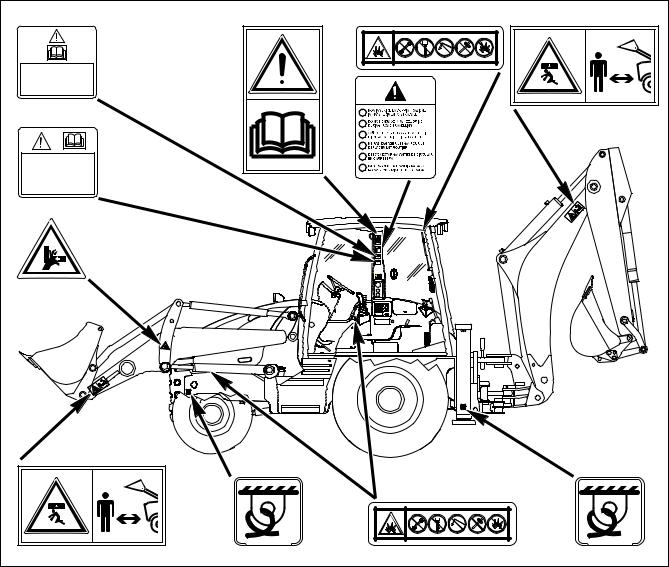
2.1.1 POSITION OF THE SAFETY PLATES
qThe safety plates must always be legible and in good conditions; for this reason, if they are dirty with dust, oil or grease, it is necessary to clean them with a solution made of water and detergent. Do not use fuel, petrol or solvents.
q If the plates are damaged, ask for new ones to Komatsu or to your Komatsu Dealer.
q In case of replacement of a component provided with a safety plate, make sure that this plate is applied also on the new piece.
qThe machine can be provided with other plates in addition to those indicated below; in any case, keep also to the instructions given in the additional plates.
DURANTE I TRASFERIMENTI |
|
|
SU STRADA I PEDALI FRENO |
|
|
DEVONO ESSERE COLLEGATI |
|
|
CON APPOSITO SPINOTTO |
|
|
|
I |
|
|
GB |
|
|
D |
|
|
F |
|
|
E |
|
PRIMA DI PARTIRE PER IL |
P |
|
TRASFERIMENTO SU |
||
|
||
STRADA BLOCCARE LA LEVA |
|
|
COMANDO PALA! |
|
|
|
kg |
|
|
000 |
|
|
L1 |
|
|
SW |
|
|
RKA13480 |
|
20 |
|

SAFETY, NOISE AND VIBRATION PLATES
SWL |
10 |
00 |
|
|
kg |
||
|
|
|
|
|
|
|
RKA13490 |
42N-93-11320 |
42N-93-11310 |
RKAB4740 |
21 |

SAFETY, NOISE AND VIBRATION PLATES
2.1.2 PICTOGRAMS AND RELEVANT MEANINGS
The warning and danger signs applied onto the machine are accompanied by or illustrated through pictograms. The personnel in charge with handling and maintenance operations must know the symbols contained in the pictograms perfectly; the symbols and the relevant meanings are explained in the following list.
WORK AREA
q Do not approach or stand in the equipment operating radius when the boom and the bucket are lifted.
42N-93-11380
DO NOT OPEN THE ENGINE HOOD
q Do not open or remove the hood when the engine is running.
RKA14690
42N-93-11370 |
RKA14700 |
HYDRAULIC OIL TOPPING UP
q (Only for machines in which synthetic biodegradable oil type HEES is used)
OVERTURNING THE FORKS
q When overturning the forks for use or storage, be very careful, since hands and feet may be seriously injured or even cut off.
BIO-OIL
42N-93-11370
RKA14710
RKA14720 |
22
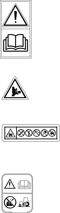
CONSULT THE MANUAL
q Carefully read the contents of the manual before using the machine or performing maintenance operations.
SAFETY, NOISE AND VIBRATION PLATES
42N-93-11130 |
RKA14730 |
RISK OF CRUSHING
q Do not touch or stand near moving parts, since your hands may be crushed or cut off.
42N-93-11220
RKA14740
PRECAUTIONS TO BE TAKEN WHEN HANDLING THE GAS SHOCK ABSORBERS
q Do not remove the shock absorber.
q Do not bring the shock absorber near sparks or naked flames.
qDo not make holes in the shock absorber, do not weld or use oxyhydrogen flames.
q Do not hit the shock absorber.
DO NOT START THE ENGINE WITH INCORRECT PROCEDURES
q Start the engine and operate the machine only while seated with fastened safety belt.
q Do not attempt to start the engine by causing a short-circuit with the terminals of the starter.
This may cause serious injury and even death.
395-93-11330
RKA14750
42N-93-11350
RKA14760
23

SAFETY, NOISE AND VIBRATION PLATES
LOCK THE LOADER CONTROL
q When it is necessary to travel on roads, lock the loader control lever before starting.
PRIMA DI PARTIRE PER IL
TRASFERIMENTO SU
STRADA BLOCCARE LA LEVA
COMANDO PALA!
42N-93-12460
RKA14770
CONNECT THE BRAKE PEDALS
q When the machine travels on roads, the brake pedals must be connected with the apposite pin.
DURANTE I TRASFERIMENTI
SU STRADA I PEDALI FRENO
DEVONO ESSERE COLLEGATI
CON APPOSITO SPINOTTO
42N-93-11110
RKA14780
DO NOT ENGAGE THE 4WD
q When the machine travels on roads, do not engage the 4WD.
I
GB 


D
F
E
P
42N-93-11120
RKA14790
HYDRAULIC OIL TOPPING UP
37A-98-12210
RKA14800
HYDRAULIC OIL LEVEL
37A-98-12290
RKA14810
24

SAFETY, NOISE AND VIBRATION PLATES
HYDRAULIC OIL FILTER
37A-98-12310
RKA14820
REFUELLING
D
37A-98-12240
RKA14830
FUEL FILTER
D
37A-98-12250
RKA14840
ENGINE LUBRICATING OIL FILTER
37A-98-12230
RKA14850
ENGINE AIR SUCTION FILTER
37A-98-12260
RKA14860
ENGINE COOLANT
37A-98-12340
RKA14870
25

SAFETY, NOISE AND VIBRATION PLATES
COOLANT PRESSURE
37A-98-12270
RKA14880
TRANSMISSION OIL LEVEL
395-93-11440
RKA14590
TRANSMISSION OIL FILTER
395-93-11420
RKA14580
POWER OUTLET
12 V
42N-93-11270
RKA14890
BOOM LOCK
42N-93-11320
RKA14900
SWING LOCK
42N-93-11310
RKA14910
26

SAFETY, NOISE AND VIBRATION PLATES
ANCHORAGE POINT
42N-93-11360
RKA14920
EMERGENCY EXIT
42N-93-11260
RKA14930
BRAKE OIL
B
AKE R
OI L
L IO
EKAR
B
RKA14940
DO NOT LIFT MORE THAN 1000 kg

 SWL 1000 Kg

RKA14950
27
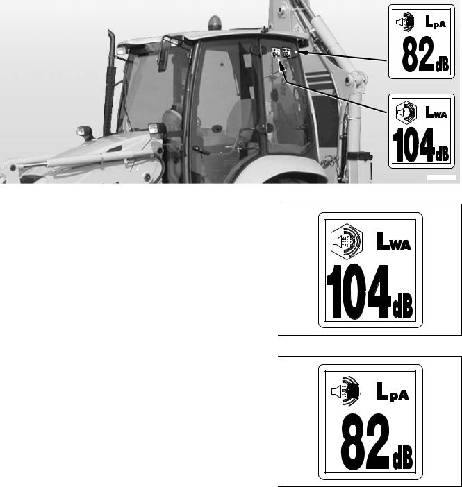
SAFETY, NOISE AND VIBRATION PLATES
2.1.3 POSITION OF THE NOISE PLATES ON MACHINES WITH CAB
q The noise plates must always be legible and in good conditions; for this reason, if they are dirty with dust, oil or grease, it is necessary to clean them with a solution made of water and detergent.
Do not use fuel, petrol or solvents.
q If the plates are damaged, ask for new ones to Komatsu or to your Komatsu Dealer.
q In case of replacement of a component provided with a noise plate, make sure that this plate is applied also on the new piece.
ISO 6396
2000/14/EC
RKAB4750
NOISE OUTSIDE THE CAB
q This value indicates the noise level outside the machine and refers to the noise perceived by persons in the vicinity of the work area.
RWA37720
NOISE INSIDE THE CAB
q This value indicates the maximum noise level perceived by the operator’s ears inside the cab when this is completely closed.
RWA37730
28
Loading...