


 Loading...
SEBM006410
DIESEL ENGINE
© 2003 1 |
|
All Rights Reserved |
00-1 |
Printed in Japan 05-03(01) |
(10)
CONTENTS
01 GENERAL |
No. of page |
......................................................................... 01-1 |
11 STRUCTURE AND FUNCTION ....................................... |
11-1 |
12 TESTING AND ADJUSTING ........................................... |
12-1 |
13 DISASSEMBLY AND ASSEMBLY .................................. |
13-1 |
14 MAINTENANCE STANDARD .......................................... |
14-1 |
15 REPAIR AND REPLACEMENT OF PARTS ..................... |
15-1 |
00-2
615002
2

LIST OF REVISED PAGES
The affected pages are indicated by the use of the following marks. It is requested that necessary actions be taken to these pages according to the table below.
Mark |
Indication |
Action required |
|
|
|
|
|
|
○ |
Page to be newly added |
Add |
|
|
|
|
|
‡ |
Page to be replaced |
Replace |
|
|
|
|
( |
) |
Page to be deleted |
Discard |
|
|
|
|
Pages having no marks are those previously revised or made additions.
615002
LIST OF REVISED PAGE
Mark |
Page |
Time of |
Mark |
Page |
Time of |
Mark |
Page |
Time of |
Mark |
Page |
Time of |
Mark |
Page |
Time of |
revision |
revision |
revision |
revision |
revision |
||||||||||
|
|
|
|
|
|
|
|
|
|
|
|
|
|
|
o |
00-1 |
(10) |
|
01-2 |
(9) |
|
01-9-15 |
(9) |
|
11-8 |
|
|
11-34 |
|
|
00-2 |
(2) |
|
01-3 |
(9) |
|
01-10 |
(9) |
|
11-10 |
(7) |
|
11-35 |
(9) |
o |
00-2-1 (10) |
|
01-3-1 |
(9) |
|
01-11 |
(9) |
|
11-11 |
|
|
11-36 |
|
|
o |
00-2-2 (10) |
|
01-3-2 |
(9) |
|
01-11-1 (9) |
|
11-12 |
|
|
11-37 |
|
||
o |
00-2-3 (10) |
|
01-4 |
(9) |
|
01-11-2 (9) |
|
11-14 |
|
|
11-38 |
|
||
o |
00-3 |
|
|
01-4-1 |
(8) |
|
01-11-3 (9) |
|
11-15 |
|
|
11-39 |
(8) |
|
o |
00-4 |
|
|
01-4-2 |
(9) |
|
01-11-4 (9) |
|
11-16 |
|
|
11-40 |
|
|
o |
00-5 |
|
|
01-4-3 |
(9) |
|
01-11-5 (9) |
|
11-17 |
|
|
11-41 |
(8) |
|
o |
00-6 |
|
|
01-4-4 |
(9) |
|
01-11-6 (9) |
|
11-17-1 (9) |
|
11-42 |
|
||
o |
00-7 |
|
|
01-5 |
(3) |
|
01-11-7 (9) |
|
11-17-2 (8) |
|
11-43 |
|
||
o |
00-8 |
|
|
01-6 |
(2) |
|
01-11-8 (9) |
|
11-17-3 (8) |
|
11-44 |
(8) |
||
o |
00-9 |
|
|
01-7 |
(2) |
|
01-11-9 |
(9) |
|
11-17-4 (8) |
|
11-45 |
(9) |
|
o |
00-10 |
|
|
01-8 |
(2) |
|
01-11-10 (9) |
|
11-18 |
(8) |
|
11-47 |
|
|
o |
00-11 |
|
|
01-9 |
(2) |
|
01-12 |
(9) |
|
11-20 |
|
|
11-48 |
(9) |
o |
00-12 |
|
|
01-9-1 |
(8) |
|
01-12-1 (9) |
|
11-21 |
|
|
11-49 |
|
|
o |
00-13 |
|
|
01-9-2 |
(8) |
|
01-12-2 (9) |
|
11-22 |
|
|
11-50 |
(9) |
|
o |
00-14 |
|
|
01-9-3 |
(8) |
|
01-12-3 (9) |
|
11-22-1 (8) |
|
11-51 |
|
||
o |
00-15 |
|
|
01-9-4 |
(8) |
|
01-12-4 (8) |
|
11-22-2 (9) |
|
11-52 |
(9) |
||
o |
00-16 |
|
|
01-9-5 |
(8) |
|
01-13 |
(9) |
|
11-24 |
|
|
11-53 |
|
o |
00-17 |
|
|
01-9-6 |
(8) |
|
01-14 |
(9) |
|
11-25 |
|
|
11-54 |
(9) |
o |
00-18 |
|
|
01-9-7 |
(8) |
|
|
|
|
11-26 |
(8) |
|
11-55 |
(9) |
o |
00-19 |
|
|
01-9-8 |
(8) |
|
11-1 |
(9) |
|
11-27 |
(8) |
|
11-56 |
(9) |
o |
00-20 |
|
|
01-9-9 |
(8) |
|
11-2 |
|
|
11-28 |
(8) |
|
11-57 |
(9) |
o |
00-21 |
|
|
01-9-10 |
(8) |
|
11-3 |
(9) |
|
11-29 |
(8) |
|
11-58 |
(9) |
o |
00-22 |
|
|
01-9-11 |
(9) |
|
11-4 |
|
|
11-30 |
|
|
11-59 |
(9) |
|
|
|
|
01-9-12 |
(9) |
|
11-5 |
|
|
11-31 |
|
|
11-60 |
(9) |
|
01-1 |
(8) |
|
01-9-13 |
(9) |
|
11-6 |
(9) |
|
11-32 |
|
|
11-61 |
(9) |
|
01-1-1 |
(9) |
|
01-9-14 |
(9) |
|
11-7 |
|
|
11-33 |
|
|
11-62 |
(9) |
|
|
|
|
|
|
|
|
|
|
|
|
|
|
|
00-2-1
(10)

LIST OF REVISED PAGES
Mark |
Page |
Time of |
Mark |
Page |
Time of |
Mark |
Page |
Time of |
Mark |
Page |
Time of |
Mark |
Page |
Time of |
revision |
revision |
revision |
revision |
revision |
||||||||||
|
|
|
|
|
|
|
|
|
|
|
|
|
|
|
|
11-63 |
(9) |
o |
12-11-1 |
(10) |
|
12-101 |
|
|
13-1 |
(1) |
|
13-42 |
(1) |
|
11-64 |
(9) |
|
12-12 |
(5) |
|
12-102 |
|
|
13-2 |
(1) |
|
13-43 |
(1) |
|
11-65 |
(9) |
|
12-12-1 (5) |
|
12-103 |
|
|
13-3 |
(1) |
|
13-44 |
(1) |
|
|
11-67 |
|
|
12-12-2 (4) |
|
12-104 |
|
|
13-4 |
(1) |
|
13-45 |
(4) |
|
|
11-68 |
|
o |
12-12-3 |
(10) |
|
12-105 |
|
|
13-5 |
(1) |
|
13-46 |
(4) |
|
11-69 |
|
|
12-12-4 (9) |
|
12-106 |
|
|
13-6 |
(1) |
|
13-47 |
(1) |
|
|
11-70 |
|
o |
12-12-5 |
(10) |
|
12-107 |
|
|
13-7 |
(1) |
|
13-48 |
(1) |
|
11-71 |
|
o |
12-12-6 |
(10) |
o |
12-108 |
(10) |
|
13-8 |
(1) |
|
13-49 |
(1) |
|
11-72 |
(9) |
|
12-12-8 (9) |
o |
12-109 |
(10) |
|
13-9 |
(1) |
|
13-50 |
(1) |
|
|
11-73 |
(3) |
|
12-12-9 |
(4) |
|
12-110 |
(8) |
|
13-10 |
(1) |
|
13-51 |
(4) |
|
11-74 |
(3) |
|
12-12-10 (4) |
o |
12-111 |
(10) |
|
13-11 |
(1) |
|
13-52 |
(1) |
|
|
11-75 |
(7) |
|
12-12-11 (8) |
o |
12-112 |
(10) |
|
13-12 |
(1) |
|
13-53 |
(1) |
|
|
11-76 |
(9) |
|
12-12-12 (8) |
|
12-113 |
(8) |
|
13-13 |
(1) |
|
13-54 |
(1) |
|
|
11-77 |
(9) |
|
12-12-13 (9) |
o |
12-114 |
(10) |
|
13-14 |
(1) |
|
13-55 |
(1) |
|
|
11-78 |
(9) |
|
12-12-14 (9) |
o |
12-115 |
(10) |
|
13-15 |
(1) |
|
|
|
|
|
11-79 |
(9) |
|
12-12-15 (9) |
|
12-116 |
(8) |
|
13-16 |
(1) |
|
|
|
|
|
11-80 |
(9) |
o |
12-12-16 (10) |
|
12-117 |
|
|
13-17 |
(1) |
|
14-1 |
|
|
o |
11-81 |
(10) |
o |
12-12-17 (10) |
|
12-118 |
(8) |
|
13-18 |
(1) |
|
14-2 |
(4) |
|
9 |
11-81-1 |
(10) |
|
12-12-18 (8) |
|
12-119 |
|
|
13-19 |
(1) |
|
14-3 |
|
|
o |
11-82 |
(10) |
|
12-12-19 (6) |
|
12-120 |
(8) |
|
13-21 |
(1) |
|
14-4 |
(8) |
|
o |
11-83 |
(10) |
|
12-12-20 (7) |
|
12-121 |
|
|
13-22 |
(4) |
|
14-6 |
(2) |
|
|
11-86 |
|
o |
12-12-21 (10) |
|
12-122 |
(8) |
|
13-23 |
(1) |
|
14-7 |
|
|
|
11-87 |
|
9 |
12-12-22 (10) |
|
12-123 |
(8) |
|
13-24 |
(1) |
|
14-8 |
(3) |
|
|
|
|
|
12-13 |
(4) |
|
12-124 |
(8) |
|
13-25 |
(1) |
|
14-9 |
|
|
|
|
|
12-13-1 (8) |
|
12-125 |
(5) |
|
13-26 |
(4) |
|
14-10 |
|
|
|
12-1 |
|
|
12-13-2 (9) |
|
12-126 |
(1) |
|
13-27 |
(4) |
|
14-11 |
|
|
|
12-2 |
|
|
12-13-3 (9) |
|
12-128 |
(9) |
|
13-28 |
(4) |
|
14-12 |
|
|
|
12-3 |
|
|
12-14 |
(9) |
|
12-129 |
(9) |
|
13-29 |
(1) |
|
14-13 |
|
|
12-4 |
(4) |
|
12-15 |
(9) |
|
12-130 |
(9) |
|
13-30 |
(1) |
|
14-14 |
|
|
12-5 |
(4) |
|
12-15-1 (9) |
|
12-131 |
(9) |
|
13-31 |
(4) |
|
14-15 |
|
|
|
12-6 |
(1) |
|
12-15-2 (9) |
|
12-132 |
(9) |
|
13-32 |
(4) |
|
14-16 |
|
|
|
12-7 |
(9) |
|
12-16 |
(9) |
|
12-133 |
(9) |
|
13-33 |
(4) |
|
14-18 |
(2) |
|
12-7-1 |
(1) |
|
12-17 |
(9) |
|
12-134 |
(9) |
|
13-34 |
(4) |
|
14-19 |
|
|
12-7-2 |
(1) |
|
12-18 |
(9) |
|
12-135 |
(9) |
|
13-35 |
(1) |
|
14-20 |
|
|
12-7-3 |
(9) |
|
12-19 |
(9) |
|
12-136 |
(9) |
|
13-36 |
(1) |
|
14-21 |
|
|
12-7-4 |
(1) |
|
12-20 |
(9) |
|
12-137 |
(9) |
|
13-37 |
(5) |
|
14-22 |
|
|
12-8 |
(1) |
|
12-21 |
(9) |
|
12-138 |
(9) |
|
13-38 |
(1) |
|
14-23 |
(4) |
|
12-9 |
|
|
12-22 |
(9) |
|
12-139 |
(9) |
|
13-39 |
(1) |
|
14-24 |
(4) |
|
12-10 |
|
|
12-23 |
(9) |
|
|
|
|
13-40 |
(1) |
|
14-25 |
|
o |
12-11 |
(10) |
|
|
|
|
|
|
|
13-41 |
(1) |
|
14-26 |
(8) |
|
|
|
|
|
|
|
|
|
|
|
|
|
|
|
00-2-2
615002
(10)

LIST OF REVISED PAGES
615002
Mark Page |
Time of |
Mark Page |
Time of |
Mark Page |
Time of |
Mark Page |
Time of |
Mark Page |
Time of |
revision |
revision |
revision |
revision |
revision |
14-27
14-28
14-29
14-30
o |
15-1 |
(10) |
|
15-2 |
|
|
15-3 |
|
|
15-4 |
(3) |
|
15-5 |
(8) |
|
15-6 |
|
|
15-7 |
(4) |
|
15-8 |
|
|
15-9 |
(4) |
|
15-10 |
|
|
15-11 |
|
|
15-12 |
(8) |
|
15-13 |
|
|
15-14 |
|
|
15-15 |
|
|
15-16 |
|
|
15-17 |
|
|
15-18 |
(9) |
|
15-18-1 |
(8) |
915-18-2 (10)
915-18-3 (10)
15-19 (9)
15-20
15-21
15-22
15-23
15-24 (9)
15-25 (9)
15-26
15-27
15-28
00-2-3
(10)

SAFETY |
SAFETY NOTICE |
SAFETY
SAFETY NOTICE
IMPORTANT SAFETY NOTICE
Proper service and repair is extremely important for safe machine operation. The service and repair techniques recommended by Komatsu and described in this manual are both effective and safe. Some of these techniques require the use of tools specially designed by Komatsu for the specific purpose.
To prevent injury to workers, the symbol ¤is used to mark safety precautions in this manual. The cautions accompanying these symbols should always be followed carefully. If any dangerous situation arises or may possibly arise, first consider safety, and take the necessary actions to deal with the situation.
GENERAL PRECAUTIONS
Mistakes in operation are extremely dangerous. Read the Operation and Maintenance Manual carefully BEFORE operating the machine.
1.Before carrying out any greasing or repairs, read all the precautions given on the decals which are fixed to the machine.
2.When carrying out any operation, always wear safety shoes and helmet. Do not wear loose work clothes, or clothes with buttons missing.
•Always wear safety glasses when hitting parts with a hammer.
•Always wear safety glasses when grinding parts with a grinder, etc.
3.If welding repairs are needed, always have a trained, experienced welder carry out the work. When carrying out welding work, always wear welding gloves, apron, hand shield, cap and other clothes suited for welding work.
4.When carrying out any operation with two or more workers, always agree on the operating procedure before starting. Always inform your fellow workers before starting any step of the operation. Before starting work, hang UNDER REPAIR signs on the controls in the operator's compartment.
5.Keep all tools in good condition and learn the correct way to use them.
6.Decide a place in the repair workshop to keep tools and removed parts. Always keep the tools and parts in their correct places. Always keep the work area clean and make sure that there is no dirt or oil on the floor. Smoke only in the areas provided for smoking. Never smoke while working.
PREPARATIONS FOR WORK
7.Before adding oil or making any repairs, park the machine on hard, level ground, and block the wheels or tracks to prevent the machine from moving.
8.Before starting work, lower blade, ripper, bucket or any other work equipment to the ground. If this is not possible, insert the safety pin or use blocks to prevent the work equipment from falling. In addition, be sure to lock all the control levers and hang warning signs on them.
9.When disassembling or assembling, support the machine with blocks, jacks or stands before starting work.
10.Remove all mud and oil from the steps or other places used to get on and off the machine. Always use the handrails, ladders or steps when getting on or off the machine. Never jump on or off the machine. If it is impossible to use the handrails, ladders or steps, use a stand to provide safe footing.
00-3
SAFETY |
SAFETY NOTICE |
PRECAUTIONS DURING WORK
11.When removing the oil filler cap, drain plug or hydraulic pressure measuring plugs, loosen them slowly to prevent the oil from spurting out.
Before disconnecting or removing components of the oil, water or air circuits, first remove the pressure completely from the circuit.
12.The water and oil in the circuits are hot when the engine is stopped, so be careful not to get burned.
Wait for the oil and water to cool before carrying out any work on the oil or water circuits.
13.Before starting work, remove the leads from the battery. Always remove the lead from the negative (–) terminal first.
14.When raising heavy components, use a hoist or crane.
Check that the wire rope, chains and hooks are free from damage.
Always use lifting equipment which has ample capacity.
Install the lifting equipment at the correct places. Use a hoist or crane and operate slowly to prevent the component from hitting any other part. Do not work with any part still raised by the hoist or crane.
15.When removing covers which are under internal pressure or under pressure from a spring, always leave two bolts in position on opposite sides. Slowly release the pressure, then slowly loosen the bolts to remove.
16.When removing components, be careful not to break or damage the wiring. Damaged wiring may cause electrical fires.
17.When removing piping, stop the fuel or oil from spilling out. If any fuel or oil drips onto the floor, wipe it up immediately. Fuel or oil on the floor can cause you to slip, or can even start fires.
18.As a general rule, do not use gasoline to wash parts. In particular, use only the minimum of gasoline when washing electrical parts.
19.Be sure to assemble all parts again in their original places.
Replace any damaged parts with new parts.
•When installing hoses and wires, be sure that they will not be damaged by contact with other parts when the machine is being operated.
20.When installing high pressure hoses, make sure that they are not twisted. Damaged tubes are dangerous, so be extremely careful when installing tubes for high pressure circuits. Also, check that connecting parts are correctly installed.
21.When assembling or installing parts, always use the specified tightening torques. When installing protective parts such as guards, or parts which vibrate violently or rotate at high speed, be particularly careful to check that they are installed correctly.
22.When aligning two holes, never insert your fingers or hand. Be careful not to get your fingers caught in a hole.
23.When measuring hydraulic pressure, check that the measuring tool is correctly assembled before taking any measurements.
24.Take care when removing or installing the tracks of track-type machines.
When removing the track, the track separates suddenly, so never let anyone stand at either end of the track.
00-4

FOREWORD |
GENERAL |
FOREWORD
GENERAL
This shop manual has been prepared as an aid to improve the quality of repairs by giving the serviceman an accurate understanding of the product and by showing him the correct way to perform repairs and make judgements. Make sure you understand the contents of this manual and use it to full effect at every opportunity.
This shop manual mainly contains the necessary technical information for operations performed in a service workshop. For ease of understanding, the manual is divided into the following chapters; these chapters are further divided into the each main group of components.
STRUCTURE AND FUNCTION
This section explains the structure and function of each component. It serves not only to give an understanding of the structure, but also serves as reference material for troubleshooting.
In addition, this section may contain hydraulic circuit diagrams, electric circuit diagrams, and maintenance standards.
TESTING AND ADJUSTING
This section explains checks to be made before and after performing repairs, as well as adjustments to be made at completion of the checks and repairs.
Troubleshooting charts correlating "Problems" with "Causes" are also included in this section.
DISASSEMBLY AND ASSEMBLY
This section explains the procedures for removing, installing, disassembling and assembling each component, as well as precautions for them.
MAINTENANCE STANDARD
This section gives the judgment standards for inspection of disassembled parts. The contents of this section may be described in STRUCTURE AND FUNCTION.
OTHERS
This section mainly gives hydraulic circuit diagrams and electric circuit diagrams.
In addition, this section may give the specifications of attachments and options together.
NOTICE
The specifications contained in this shop manual are subject to change at any time and without any advance notice. Use the specifications given in the book with the latest date.
00-5
FOREWORD |
HOW TO READ THE SHOP MANUAL |
HOW TO READ THE SHOP MANUAL
VOLUMES
Shop manuals are issued as a guide to carrying out repairs. They are divided as follows:
Chassis volume: Issued for every machine model Engine volume: Issued for each engine series
Electrical volume: |
Each issued as one |
|
}· modelsvolume to cover all |
||
Attachments volume: |
These various volumes are designed to avoid duplicating the same information. Therefore, to deal with all repairs for any model , it is necessary that chassis, engine, electrical and attachment volumes be available.
DISTRIBUTION AND UPDATING
Any additions, amendments or other changes will be sent to KOMATSU distributors. Get the most up-to- date information before you start any work.
FILING METHOD
1.See the page number on the bottom of the page. File the pages in correct order.
2.Following examples show how to read the page number.
Example 1 (Chassis volume):
10 - 3
Item number (10. Structure and Function)
Consecutive page number for each item.
Example 2 (Engine volume):
12 - 5
Unit number (1. Engine)
Item number (2. Testing and Adjusting)
Consecutive page number for each item.
3.Additional pages: Additional pages are indicated by a hyphen (-) and number after the page number. File as in the example.
Example:
10-4 |
|
|
|
|
12-203 |
|
10-4-1 |
|
|
Added pages |
|
|
12-203-1 |
|
|
|
|
|||
10-4-2 |
|
|
|
|
12-203-2 |
|
|
|
|
|
|
||
10-5 |
|
|
|
|
12-204 |
|
REVISED EDITION MARK
When a m anual is revis ed, an edition mark (123....) is recorded on the bottom of the pages.
REVISIONS
Revised pages are shown in the LIST OF REVISED PAGES next to the CONTENTS page.
SYMBOLS
So that the shop manual can be of ample practical use, important safety and quality portions are marked with the following symbols.
Symbol |
Item |
Remarks |
|
|
|
|
|
|
|
Special safety precautions |
|
¤ |
Safety |
are necessary when per- |
|
|
|
forming the work. |
|
|
|
|
|
|
|
Special technical precau- |
|
|
|
tions or other precautions |
|
s |
Caution |
for preserving standards |
|
|
|
are necessary when per- |
|
|
|
forming the work. |
|
|
|
|
|
|
|
Weight of parts of sys- |
|
|
|
tems. Caution necessary |
|
4 |
Weight |
when selecting hoisting |
|
|
|
wire, or when working pos- |
|
|
|
ture is important, etc. |
|
|
|
|
|
3 |
Tightening |
Places that require special |
|
attention for the tightening |
|||
|
torque |
||
|
torque during assembly. |
||
|
|
||
|
|
|
|
|
|
Places to be coated with |
|
2 |
Coat |
adhesives and lubricants, |
|
|
|
etc. |
|
|
|
|
|
|
|
Places where oil, water or |
|
5 |
Oil, water |
fuel must be added, and |
|
|
|
the capacity. |
|
|
|
|
|
|
|
Places where oil or water |
|
6 |
Drain |
m u s t b e d r a in e d , a nd |
|
|
|
quantity to be drained. |
|
|
|
|
00-6
FOREWORD |
HOISTING INSTRUCTIONS |
HOISTING INSTRUCTIONS
HOISTING
¤Heavy parts (25 kg or more) must be lifted with a hoist, etc. In the DISASSEMBLY AND ASSEMBLY section, every part weighing 25 kg or more is indicated clearly with the symbol 4
•If a part cannot be smoothly removed from the machine by hoisting, the following checks should be made:
1)Check for removal of all bolts fastening the part to the relative parts.
2)Check for existence of another part causing interference with the part to be removed.
WIRE ROPES
1)Use adequate ropes depending on the weight of parts to be hoisted, referring to the table below:
Wire ropes (Standard "Z" or "S" twist ropes
without galvanizing)
Rope diameter |
Allowable load |
|
|
|
|
mm |
kN |
tons |
|
|
|
10 |
9.8 |
1.0 |
11.5 |
13.7 |
1.4 |
12.5 |
15.7 |
1.6 |
14 |
21.6 |
2.2 |
16 |
27.5 |
2.8 |
18 |
35.3 |
3.6 |
20 |
43.1 |
4.4 |
22.4 |
54.9 |
5.6 |
30 |
98.1 |
10.0 |
40 |
176.5 |
18.0 |
50 |
274.6 |
28.0 |
60 |
392.2 |
40.0 |
|
|
|
The allowable load value is estimated to be onesixth or one-seventh of the breaking strength of the rope used.
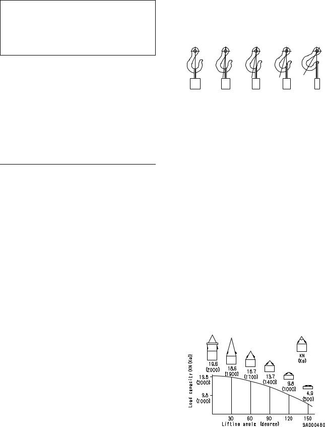
2)Sling wire ropes from the middle portion of the hook.
Slinging near the edge of the hook may cause the rope to slip off the hook during hoisting, and a serious accident can result. Hooks have maximum strength at the middle portion.
100% |
88% |
79% |
71% |
41% |
SAD00479
3)Do not sling a heavy load with one rope alone, but sling with two or more ropes symmetrically wound onto the load.
¤Slinging with one rope may cause turning of the load during hoisting, untwisting of the rope, or slipping of the rope from its original winding position on the load, which can result in a dangerous accident.
4)Do not sling a heavy load with ropes forming a wide hanging angle from the hook.
When hoisting a load with two or more ropes, the force subjected to each rope will increase with the hanging angles. The table below shows the variation of allowable load kN {kg} when hoisting is made with two ropes, each of which is allowed to sling up to 9.8 kN {1000 kg} vertically, at various hanging angles.
When two ropes sling a load vertically, up to 19.6 kN {2000 kg} of total weight can be suspended. This weight becomes 9.8 kN {1000 kg} when two ropes make a 120° hanging angle. On the other hand, two ropes are subjected to an excessive force as large as 39.2 kN {4000 kg} if they sling a 19.6 kN {2000 kg} load at a lifting angle of 150°.
00-7
FOREWORD METHOD OF DISASSEMBLING, CONNECTING PUSH-PULL TYPE COUPLER
METHOD OF DISASSEMBLING, CONNECTING PUSH-PULL TYPE COUPLER
¤Before carrying out the following work, release |
Type 1 |
the residual pressure from the hydraulic tank. |
|
For details, see TESTING AND ADJUSTING, |
|
Releasing residual pressure from hydraulic |
|
tank. |
|
¤Even if the residual pressure is released from |
|
the hydraulic tank, some hydraulic oil flows out |
|
when the hose is disconnected. Accordingly, |
|
prepare an oil receiving container. |
|
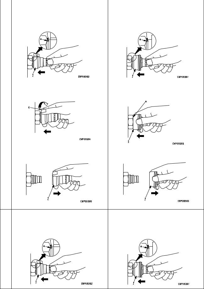
Disconnection
1)Release the residual pressure from the hydraulic tank. For details , see TES TIN G AN D ADJUSTING, Releasing residual pressure from hydraulic tank.
2)Hold adapter (1) and push hose joint (2) into mating adapter (3). (See Fig. 1)
The adapter can be pushed in about 3.5 mm.
Do not hold rubber cap portion (4).
3)After hose joint (2) is pushed into adapter (3), press rubber cap portion (4) against (3) until it clicks. (See Fig. 2)
4)Hold hose adapter (1) or hose (5) and pull it out. (See Fig. 3)
Since some hydraulic oil flows out, prepare an oil receiving container.
Connection
1)Hold hose adapter (1) or hose (5) and insert it in mating adapter (3), aligning them with each other. (See Fig. 4)
Do not hold rubber cap portion (4).
2)After inserting the hose in the mating adapter
perfectly, pull it back to check its connecting condition. (See Fig. 5)
When the hose is pulled back, the rubber cap portion moves toward the hose about 3.5 mm. This does not indicate abnormality, however.
00-8
FOREWORD |
METHOD OF DISASSEMBLING, CONNECTING PUSH-PULL TYPE COUPLER |
|
|
|
|
|
Type 2 |
Type 3 |
|
|
|
1) Hold the mouthpiece of the tightening portion |
1) Hold the mouthpiece of the tightening portion |
|
and push body (2) in straight until sliding pre- |
and push body (2) in straight until sliding pre- |
|
vention ring (1) contacts contact surface a of |
vention ring (1) contacts contact surface a of |
|
the hexagonal portion at the male end. |
the hexagonal portion at the male end. |
|
2) Hold in the condition in Step 1), and turn |
2) Hold in the condition in Step 1), and push |
lever (4) to the right (clockwise). |
until cover (3) contacts contact surface a of |
|
the hexagonal portion at the male end. |
Disassembly
3) Hold in the condition in Steps 1) and 2), and |
3) Hold in the condition in Steps 1) and 2), and |
pull out whole body (2) to disconnect it. |
pull out whole body (2) to disconnect it. |
• Hold the mouthpiece of the tightening portion • |
Hold the mouthpiece of the tightening portion |
and push body (2) in straight until sliding pre- |
and push body (2) in straight until sliding pre- |
vention ring (1) contacts contact surface a of |
vention ring (1) contacts contact surface a of |
the hexagonal portion at the male end to con- |
the hexagonal portion at the male end to con- |
nect it. |
nect it. |
Connection
00-9
FOREWORD |
COATING MATERIALS |
COATING MATERIALS
The recommended coating materials such as adhesives, gasket sealants and greases used for disassembly and assembly are listed below.
For coating materials not listed below, use the equivalent of products shown in this list.
Category |
Komatsu code |
Part No. |
Q'ty |
Container |
|
Main applications, featuresr |
|||
|
|
|
|
|
|
||||
|
|
|
|
|
• Used to prevent rubber gaskets, |
||||
|
LT-1A |
790-129-9030 |
150 g |
Tube |
|
rubber cushions, and cock plug |
|||
|
|
|
|
|
|
from coming out. |
|
||
|
|
|
|
|
|
||||
|
|
|
|
|
• Used in places requiring an imme- |
||||
|
|
|
|
|
|
diately effective, strong adhesive. |
|||
|
LT-1B |
790-129-9050 |
20 g |
Polyethylene |
|
Used for plastics (except polyeth- |
|||
|
(2 pcs.) |
container |
|
ylene, polyprophylene, tetrafluor- |
|||||
|
|
|
|
||||||
|
|
|
|
|
|
oethlene and vinyl chloride), |
|||
|
|
|
|
|
|
rubber, metal and non-metal. |
|||
|
|
|
|
|
|
||||
|
|
|
|
|
• Features: Resistance to heat and |
||||
|
LT-2 |
09940-00030 |
50 g |
Polyethylene |
|
chemicals |
|
|
|
|
container |
• |
Used for anti-loosening and seal- |
||||||
|
|
|
|
||||||
|
|
|
|
|
|
ant purpose for bolts and plugs. |
|||
|
|
|
|
|
|
||||
|
|
790-129-9060 |
Adhesive: |
|
• Used as adhesive or sealant for |
||||
|
|
1 kg |
|
|
metal, glass and plastic. |
||||
|
|
(Set of |
Hardenin |
Can |
|
|
|
|
|
|
LT-3 |
adhesive and |
|
|
|
|
|
||
|
g |
|
|
|
|
|
|||
|
|
hardening |
|
|
|
|
|
|
|
|
|
agent: |
|
|
|
|
|
|
|
|
|
agent) |
|
|
|
|
|
|
|
Adhesives |
|
500 g |
|
|
|
|
|
|
|
|
|
|
|
|
|
|
|
||
|
|
|
|
|
|
|
|
|
|
|
|
|
|
|
|
|
|
|
|
|
LT-4 |
790-129-9040 |
250 g |
Polyethylene |
• |
Used |
as |
sealant |
for machined |
|
container |
|
holes. |
|
|
|
|||
|
|
|
|
|
|
|
|
||
|
|
|
|
|
|
|
|||
|
Holtz |
790-126-9120 |
75 g |
Tube |
• |
Used as heat-resisting sealant for |
|||
|
MH 705 |
|
repairing engine. |
|
|||||
|
|
|
|
|
|
||||
|
|
|
|
|
• Quick hardening type adhesive |
||||
|
Three bond |
790-129-9140 |
50 g |
Polyethylene |
• |
Cure time: within 5 sec. to 3 min. |
|||
|
1735 |
container |
• |
Used mainly for adhesion of met- |
|||||
|
|
|
|||||||
|
|
|
|
|
|
als, rubbers, plastics and woods. |
|||
|
|
|
|
|
|
||||
|
|
|
|
|
• Quick hardening type adhesive |
||||
|
Aron-alpha |
|
|
Polyethylene |
• Quick cure type (max. strength af- |
||||
|
790-129-9130 |
2 g |
|
ter 30 minutes) |
|
||||
|
201 |
container |
|
|
|||||
|
|
|
• Used mainly for adhesion of rub- |
||||||
|
|
|
|
|
|||||
|
|
|
|
|
|
bers, plastics and metals. |
|||
|
|
|
|
|
|
||||
|
Loctite |
|
|
Polyethylene |
• Resistance to heat, chemicals |
||||
|
79A-129-9110 |
50 cc |
• Used at joint portions subject to |
||||||
|
648-50 |
container |
|||||||
|
|
|
|
high temperatures. |
|
||||
|
|
|
|
|
|
|
|||
|
|
|
|
|
|
||||
|
|
|
|
|
• Used as adhesive or sealant for |
||||
|
LG-1 |
790-129-9010 |
200 g |
Tube |
|
gaskets and packing of power |
|||
|
|
|
|
|
|
train case, etc. |
|
||
|
|
|
|
|
|
|
|
|
|
|
|
|
|
|
• Used |
as |
sealant |
for various |
|
|
|
|
|
|
|
threads, pipe joints, flanges. |
|||
|
LG-5 |
790-129-9070 |
1 kg |
Can |
• |
Used as sealant for tapered |
|||
Gasket |
|
|
|
|
|
plugs, elbows, nipples of hydrau- |
|||
sealant |
|
|
|
|
|
lic piping. |
|
|
|
|
|
|
|
|
|
|
|||
|
|
|
|
|
• |
Features: Silicon based, resist- |
|||
|
|
|
|
|
|
ance to heat, cold |
|
||
|
LG-6 |
790-129-9020 |
200 g |
Tube |
• Used as sealant for flange sur- |
||||
|
|
face, tread. |
|
||||||
|
|
|
|
|
|
|
|||
|
|
|
|
|
• mab Used as sealant for oil pan, |
||||
|
|
|
|
|
|
final drive case, etc. |
|||
|
|
|
|
|
|
|
|
|
|
00-10
FOREWORD |
COATING MATERIALS |
Category |
Komatsu code |
Part No. |
Q'ty |
Container |
|
Main applications, featuresr |
|
|
|
|
|
|
|
|
|
|
|
|
• Ftures: Silicon based, quick hard- |
|
|
|
|
|
|
|
ening type |
|
LG-7 |
790-129-9070 |
1 g |
Tube |
• |
Used as sealant for flywheel |
Adhesives |
|
|
|
|
|
housing, intake manifold, oil an, |
|
|
|
|
|
thermostat housing, etc. |
|
|
|
|
|
|
|
|
|
Three bond |
790-129-9090 |
100 g |
Tube |
• Used as heat-resisting sealant for |
|
|
1211 |
|
repairing engine. |
|||
|
|
|
|
|
||
|
|
|
|
|
|
|
|
LM-G |
09940-00051 |
60 g |
Can |
• Used as lubricant for sliding por- |
|
|
|
tion (to prevent from squeaking). |
||||
|
|
|
|
|
|
|
Molybdenum |
|
|
|
|
|
|
|
|
|
|
• Used to prevent seizure or scuf- |
||
disulphide |
|
|
|
|
||
|
|
|
|
|
fling of the thread when press fit- |
|
lubricant |
|
|
|
|
|
|
LM-P |
09940-00040 |
200 g |
Tube |
|
ting or shrink fitting. |
|
|
|
|||||
|
|
|
|
|
• Used as lubricant for linkage, |
|
|
|
|
|
|
|
bearings, etc. |
|
|
|
|
|
|
|
|
|
SYG2-400LI |
|
|
• |
General purpose type |
|
|
SYG2-350LI |
|
|
|
|
|
G2-LI |
SYG2-400LI-A |
Various |
Various |
|
|
|
|
SYG2-160LI |
|
|
|
|
|
|
SYGA-160CNLI |
|
|
|
|
|
|
|
|
|
|
|
|
|
SYG2-400CA |
|
|
• |
Used for normal temperature, |
Grease |
|
SYG2-350CA |
|
|
|
light load bearing at places in con- |
|
G2-CA |
SYG2-400CA-A |
Various |
Various |
|
tact with water or steam. |
|
|
SYG2-160CA |
|
|
|
|
|
|
SYGA-160CNCA |
|
|
|
|
|
|
|
|
|
|
|
|
Molybdenum |
|
400 g |
|
• Used for places with heavy load |
|
|
disulphide |
SYG2-400M |
(10 per |
Belows type |
|
|
|
lubricant |
|
case) |
|
|
|
|
|
|
|
|
|
|
00-11
FOREWORD |
STANDARD TIGHTENING TORQUE |
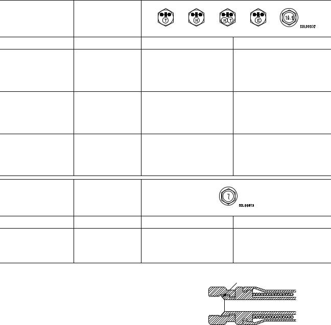
STANDARD TIGHTENING TORQUE
STANDARD TIGHTENING TORQUE TABLE (WHEN USING TORQUE WRENCH)
In the case of metric nuts and bolts for which there is no special instruction, tighten to the torque given in the table below.
Thread diameter |
Width across |
|
|
|
|
|
|
of bolt |
flats |
|
|
|
|
|
|
mm |
mm |
Nm |
|
kgm |
|||
6 |
10 |
13.2 |
0 |
1.4 |
1.35 |
0 |
0.15 |
8 |
13 |
31 0 3 |
3.2 |
0 |
0.3 |
||
10 |
17 |
66 0 7 |
6.7 |
0 |
0.7 |
||
12 |
19 |
113 0 10 |
11.5 0 1 |
||||
14 |
22 |
177 0 19 |
18 0 2 |
||||
16 |
24 |
279 0 30 |
28.5 0 3 |
||||
18 |
27 |
382 0 39 |
39 0 4 |
||||
20 |
30 |
549 0 59 |
56 0 6 |
||||
22 |
32 |
745 0 83 |
76 0 8.5 |
||||
24 |
36 |
927 0 103 |
94.5 |
0 |
10.5 |
||
27 |
41 |
1320 0 140 |
135 0 15 |
||||
30 |
46 |
1720 0 190 |
175 0 20 |
||||
33 |
50 |
2210 0 240 |
225 0 25 |
||||
36 |
55 |
2750 0 290 |
280 0 30 |
||||
39 |
60 |
3290 0 340 |
335 0 35 |
||||
Thread diameter |
Width across |
|
|
|
|
|
|
of bolt |
flats |
|
|
|
|
|
|
mm |
mm |
Nm |
|
kgm |
|||
6 |
10 |
7.85 0 1.95 |
0.8 |
0 |
0.2 |
||
8 |
13 |
18.6 0 4.9 |
1.9 |
0 |
0.5 |
||
10 |
14 |
40.2 0 5.9 |
4.1 |
0 |
0.6 |
||
12 |
27 |
82.35 0 7.85 |
8.4 |
0 |
0.8 |
||
Sealing surface
TABLE OF TIGHTENING TORQUES FOR FLARED NUTS
In the case of flared nuts for which there is no special instruction, tighten to the torque given in
the table below. |
|
|
|
|
|
SAD00483 |
|
|
|
|
|
|
|
|
|
|
|
|
|
|
Thread diameter |
Width across flat |
|
|
|
Tightening torque |
|
|
|
|
|
|
|
|
mm |
mm |
Nm |
|
|
kgm |
|
|
|
|
|
|
|
|
14 |
19 |
24.5 |
0 |
4.9 |
|
2.5 0 0.5 |
18 |
24 |
49 0 19.6 |
|
5 0 2 |
||
22 |
27 |
78.5 0 19.6 |
|
8 0 2 |
||
24 |
32 |
137.3 |
0 |
29.4 |
|
14 0 3 |
30 |
36 |
176.5 |
0 |
29.4 |
|
18 0 3 |
33 |
41 |
196.1 0 49 |
|
20 0 5 |
||
36 |
46 |
245.2 0 49 |
|
25 0 5 |
||
42 |
55 |
294.2 0 49 |
|
30 0 5 |
||
|
|
|
|
|
|
|
00-12
FOREWORD |
STANDARD TIGHTENING TORQUE |
TABLE OF TIGHTENING TORQUES FOR SPLIT FLANGE BOLTS
In the case of split flange bolts for which there is no special instruction, tighten to the torque given in the table below.
Thread diameter |
Width across flat |
|
|
|
Tightening torque |
|
|
|
|
|
|
|
|
mm |
mm |
Nm |
|
|
kgm |
|
|
|
|
|
|
|
|
10 |
14 |
65.7 |
0 |
6.8 |
|
6.7 0 0.7 |
12 |
17 |
112 0 9.8 |
|
11.5 0 1 |
||
16 |
22 |
279 |
0 |
29 |
|
28.5 0 3 |
|
|
|
|
|
|
|
TABLE OF TIGHTENING TORQUES FOR O-RING BOSS PIPING JOINTS
Unless there are special instructions, tighten the O-ring boss piping joints to the torque below.
|
Thread diameter |
Width across flat |
|
|
Tightening torque |
|
|
|
Norminal No. |
|
|
|
|
|
|
|
|
mm |
mm |
Nm |
|
kgm |
||||
|
|
|||||||
|
|
|
|
|
|
|
|
|
02 |
14 |
|
34.3 |
0 |
4.9 |
3.5 |
0 |
0.5 |
03, 04 |
20 |
Varies depending |
93.1 |
0 |
9.8 |
9.5 0 1 |
||
05, 06 |
24 |
on type of |
142.1 |
0 |
19.6 |
14.5 0 2 |
||
10, 12 |
33 |
connector. |
421.4 |
0 |
58.8 |
43 0 6 |
||
14 |
42 |
|
877.1 0 132.3 |
89.5 |
0 |
13.5 |
||
|
|
|
|
|
|
|
|
|
TABLE OF TIGHTENING TORQUES FOR O-RING BOSS PLUGS
Unless there are special instructions, tighten the O-ring boss plugs to the torque below.
|
Thread diameter |
Width across flat |
|
|
Tightening torque |
|
|
Norminal No. |
|
|
|
|
|
|
|
mm |
mm |
Nm |
|
kgm |
|||
|
|
||||||
|
|
|
|
|
|
||
08 |
08 |
14 |
7.35 0 1.47 |
0.75 |
0 0.15 |
||
10 |
10 |
17 |
11.27 0 |
1.47 |
1.15 |
0 0.15 |
|
12 |
12 |
19 |
17.64 |
0 |
1.96 |
1.8 |
0 0.2 |
14 |
14 |
22 |
22.54 |
0 |
1.96 |
2.3 |
0 0.2 |
16 |
16 |
24 |
29.4 |
0 |
4.9 |
3 0 0.5 |
|
18 |
18 |
27 |
39.2 |
0 |
4.9 |
4 0 0.5 |
|
20 |
20 |
30 |
49 0 4.9 |
5 0 0.5 |
|||
24 |
24 |
32 |
68.6 |
0 |
9.8 |
7 |
0 1 |
30 |
30 |
32 |
107.8 |
0 |
14.7 |
11 0 1.5 |
|
33 |
33 |
n |
127.4 |
0 |
19.6 |
13 0 2 |
|
36 |
36 |
36 |
151.9 |
0 |
24.5 |
15.5 0 2.5 |
|
42 |
42 |
n |
210.7 |
0 |
29.4 |
21.5 0 3 |
|
52 |
52 |
n |
323.4 |
0 |
44.1 |
33 0 4.5 |
|
|
|
|
|
|
|
|
|
00-13
FOREWORD |
STANDARD TIGHTENING TORQUE |
TIGHTENING TORQUE FOR 102 ENGINE SERIES
1)BOLT AND NUTS
Use these torques for bolts and nuts (unit: mm) of Cummins Engine.
Thread diameter |
|
Tightening torque |
|
|
|
|
|
mm |
Nm |
|
kgm |
|
|
|
|
6 |
10 0 2 |
|
1.02 0 0.20 |
8 |
24 0 4 |
|
2.45 0 0.41 |
10 |
43 0 6 |
|
4.38 0 0.61 |
12 |
77 0 12 |
|
7.85 0 1.22 |
|
|
|
|
2)EYE JOINTS
Use these torques for eye joints (unit: mm) of Cummins Engine.
Thread diameter |
|
Tightening torque |
|
|
|
|
|
mm |
Nm |
|
kgm |
|
|
|
|
6 |
8 0 2 |
|
0.81 0 0.20 |
8 |
10 0 2 |
|
1.02 0 0.20 |
10 |
12 0 2 |
|
1.22 0 0.20 |
12 |
24 0 4 |
|
2.45 0 0.41 |
14 |
36 0 5 |
|
3.67 0 0.51 |
|
|
|
|
3)TAPERED SCREWS
Use these torques for tapered screws (unit: inch) of Cummins Engine.
Thread diameter |
|
Tightening torque |
|
|
|
|
|
inch |
Nm |
|
kgm |
|
|
|
|
1 / 16 |
3 0 1 |
|
0.31 0 0.10 |
1 / 8 |
8 0 2 |
|
0.81 0 0.20 |
1 / 4 |
12 0 2 |
|
1.22 0 0.20 |
3 / 8 |
15 0 2 |
|
1.53 0 0.41 |
1 / 2 |
24 0 4 |
|
2.45 0 0.41 |
3 / 4 |
36 0 5 |
|
3.67 0 0.51 |
1 |
60 0 9 |
|
6.12 0 0.92 |
|
|
|
|
TIGHTENING TORQUE TABLE FOR HOSES (TAPER SEAL TYPE AND FACE SEAL TYPE)
Tighten the hoses (taper seal type and face seal type) to the following torque, unless otherwise specified.
Apply the following torque when the threads are coated (wet) with engine oil.
|
|
Tightening torque (Nm {kgm}) |
Taper seal |
|
Face seal type |
|||
|
|
type |
|
|||||
Nominal size |
Width across |
|
|
|
|
|
|
|
|
|
|
|
|
|
|
||
of hose |
flats |
|
Range |
Target |
Thread size |
Nominal thread |
Root diameter |
|
|
|
|
size - Threads per |
|||||
|
|
|
|
|
(mm) |
inch, Thread series |
(mm) (Reference) |
|
|
|
|
|
|
|
|
|
|
02 |
19 |
35 - 63 {3.5 - 6.5} |
44 {4.5} |
14 |
9 |
- 18UNF |
14.3 |
|
– |
||||||||
|
|
|
|
|
|
16 |
|
|
|
22 |
54 - 93 {5.5 - 9.5} |
74 {4.5} |
– |
11 |
- 16UN |
17.5 |
|
03 |
– |
|||||||
|
|
|
|
|
16 |
|
|
|
|
24 |
59 - 98 {6.0 - 10.0} |
78 {8.0} |
18 |
|
– |
– |
|
|
|
|
|
|
|
|
|
|
04 |
27 |
84 |
- 132 {8.5 - 13.5} |
103 {10.5} |
22 |
13 |
- 16UN |
20.7 |
– |
||||||||
|
|
|
|
|
|
16 |
|
|
05 |
32 |
128 |
- 186 {13.0 - 19.0} |
157 {16.0} |
24 |
1 - 14UNS |
25.4 |
|
|
|
|
|
|
|
|
|
|
06 |
36 |
177 |
- 245 {18.0 - 25.0} |
216 {22.0} |
30 |
3 |
- 12UNF |
30.3 |
1 – |
||||||||
|
|
|
|
|
|
16 |
|
|
(10) |
41 |
177 |
- 245 {18.0 - 25.0} |
216 {22.0} |
33 |
|
– |
– |
|
|
|
|
|
|
|
|
|
(12) |
46 |
197 |
- 294 {20.0 - 30.0} |
245 {25.0} |
36 |
|
– |
– |
|
|
|
|
|
|
|
|
|
(14) |
55 |
246 |
- 343 {25.0 - 35.0} |
294 {30.0} |
42 |
|
– |
– |
|
|
|
|
|
|
|
|
|
00-14

FOREWORD |
ELECTRIC WIRE CODE |
ELECTRIC WIRE CODE
In the wiring diagrams, various colors and symbols are employed to indicate the thickness of wires. This wire code table will help you understand WIRING DIAGRAMS.
Example: 5WB indicates a cable having a nominal number 5 and white coating with black stripe.
CLASSIFICATION BY THICKNESS
|
|
Copper wire |
|
|
|
|
|
Norminal |
|
|
|
Cable O.D. |
Current |
|
|
|
Dia. of |
Cross |
rating |
Applicable circuit |
|||
number |
Number of |
(mm) |
|||||
(A) |
|
||||||
|
strands |
section |
|
|
|||
|
strands |
(mm2) |
(mm2) |
|
|
|
|
|
|
|
|
|
|
|
|
0.85 |
11 |
0.32 |
0.88 |
2.4 |
12 |
Starting, lighting, signal |
|
etc. |
|||||||
|
|
|
|
|
|
||
|
|
|
|
|
|
|
|
2 |
26 |
0.32 |
2.09 |
3.1 |
20 |
Lighting, signal etc. |
|
|
|
|
|
|
|
|
|
5 |
65 |
0.32 |
5.23 |
4.6 |
37 |
Charging and signal |
|
|
|
|
|
|
|
|
|
15 |
84 |
0.45 |
13.36 |
7.0 |
59 |
Starting (Glow plug) |
|
|
|
|
|
|
|
|
|
40 |
85 |
0.80 |
42.73 |
11.4 |
135 |
Starting |
|
|
|
|
|
|
|
|
|
60 |
127 |
0.80 |
63.84 |
13.6 |
178 |
Starting |
|
|
|
|
|
|
|
|
|
100 |
217 |
0.80 |
109.1 |
17.6 |
230 |
Starting |
|
|
|
|
|
|
|
|
CLASSIFICATION BY COLOR AND CODE
Priori- |
Circuits |
|
|
|
|
|
|
|
||
|
|
Charging |
Ground |
Starting |
Lighting |
Instrument |
Signal |
Other |
||
ty |
Classi- |
|||||||||
|
|
|
|
|
|
|
||||
|
fication |
|
|
|
|
|
|
|
||
|
|
|
|
|
|
|
|
|
|
|
|
Pri- |
Code |
W |
B |
B |
R |
Y |
G |
L |
|
1 |
|
|
|
|
|
|
|
|
||
mary |
Color |
White |
Black |
Black |
Red |
Yellow |
Green |
Blue |
||
|
||||||||||
|
|
|||||||||
|
|
|
|
|
|
|
|
|
|
|
|
|
Code |
WR |
|
BW |
RW |
YR |
GW |
LW |
|
2 |
|
|
|
|
|
|
|
|
|
|
|
Color |
White & Red |
|
White & Black |
Red & White |
Rellow & Red |
Green & White |
Blue & White |
||
|
|
|
||||||||
|
|
|
|
|
|
|
|
|
|
|
|
|
Code |
WB |
|
BY |
RB |
YB |
GR |
LR |
|
3 |
|
|
|
|
|
|
|
|
|
|
|
Color |
White & Black |
|
Black & Yellow |
Red & Black |
Yellow & Black |
Green & Red |
Blue & Yellow |
||
|
|
|
||||||||
|
|
|
|
|
|
|
|
|
|
|
|
|
Code |
WL |
|
BR |
RY |
YG |
GY |
LY |
|
4 |
Auxi- |
|
|
|
|
|
|
|
|
|
|
|
|
|
|
|
|
|
|||
liary |
|
|
|
|
|
Yellow & |
Green & |
|
||
|
Color |
White & Blue |
|
Black & Red |
Red & Yellow |
Blue & Yellow |
||||
|
|
|
Green |
Yellow |
||||||
|
|
|
|
|
|
|
|
|||
|
|
|
|
|
|
|
|
|
|
|
|
|
Code |
WG |
|
|
RG |
YL |
GB |
LB |
|
5 |
|
|
|
|
|
|
|
|
|
|
|
Color |
White & Green |
|
|
Red & Green |
Yellow & Blue |
Green & Black |
Blue & Black |
||
|
|
|
|
|||||||
|
|
|
|
|
|
|
|
|
|
|
|
|
Code |
|
|
|
RL |
YW |
GL |
|
|
6 |
|
|
|
|
|
|
|
|
|
|
|
Color |
|
|
|
Red & Blue |
Yellow & White |
Green & Blue |
|
||
|
|
|
|
|
|
|||||
|
|
|
|
|
|
|
|
|
|
|
00-15

FOREWORD |
CONVERSION TABLE |
CONVERSION TABLE
METHOD OF USING THE CONVERSION TABLE
The Conversion Table in this section is provided to enable simple conversion of figures. For details of the method of using the Conversion Table, see the example given below.
EXAMPLE
•Method of using the Conversion Table to convert from millimeters to inches
1.Convert 55 mm into inches.
(1)Locate the number 50 in the vertical column at the left side, take this as A, then draw a horizontal line from A.
(2)Locate the number 5 in the row across the top, take this as B, then draw a perpendicular line down from B.
(3)Take the point where the two lines cross as C. This point C gives the value when converting from millimeters to inches. Therefore, 55 mm = 2.165 inches.
2.Convert 550 mm into inches.
(1)The number 550 does not appear in the table, so divide by 10 (move the decimal point one place to the left) to convert it to 55 mm.
(2)Carry out the same procedure as above to convert 55 mm to 2.165 inches.
(3)The original value (550 mm) was divided by 10, so multiply 2.165 inches by 10 (move the decimal point one place to the right) to return to the original value. This gives 550 mm = 21.65 inches.
B
Millimeters to inches
|
|
|
|
|
|
|
|
|
|
|
|
1 mm = 0.03937 in |
|
|
|
|
|
|
|
|
|
|
|
|
|
|
|
|
|
0 |
1 |
2 |
3 |
4 |
5 |
|
6 |
7 |
8 |
9 |
|
|
|
|
|
|
|
|
|
|
|
|
|
|
|
|
0 |
0 |
0.039 |
0.079 |
0.118 |
0.157 |
0.197 |
|
0.236 |
0.276 |
0.315 |
0.354 |
|
|
10 |
0.394 |
0.433 |
0.472 |
0.512 |
0.551 |
0.591 |
|
0.630 |
0.669 |
0.709 |
0.748 |
|
|
20 |
0.787 |
0.827 |
0.866 |
0.906 |
0.945 |
0.984 |
|
1.024 |
1.063 |
1.102 |
1.142 |
|
|
30 |
1.181 |
1.220 |
1.260 |
1.299 |
1.339 |
1.378 |
|
1.417 |
1.457 |
1.496 |
1.536 |
|
|
40 |
1.575 |
1.614 |
1.654 |
1.693 |
1.732 |
1.772 |
|
1.811 |
1.850 |
1.890 |
1.929 |
|
|
|
|
|
|
|
|
C |
|
|
|
|
||
|
|
|
|
|
|
|
|
|
|
2.205 |
2.244 |
2.283 |
2.323 |
A |
50 |
1.969 |
2.008 |
2.047 |
2.087 |
2.126 |
|
2.165 |
|
||||
60 |
2.362 |
2.402 |
2.441 |
2.480 |
2.520 |
2.559 |
|
2.598 |
2.638 |
2.677 |
2.717 |
||
|
|
||||||||||||
|
70 |
2.756 |
2.795 |
2.835 |
2.874 |
2.913 |
2.953 |
|
2.992 |
3.032 |
3.071 |
3.110 |
|
|
80 |
3.150 |
3.189 |
3.228 |
3.268 |
3.307 |
3.346 |
|
3.386 |
3.425 |
3.465 |
3.504 |
|
|
90 |
3.543 |
3.583 |
3.622 |
3.661 |
3.701 |
3.740 |
|
3.780 |
3.819 |
3.858 |
3.898 |
|
|
|
|
|
|
|
|
|
|
|
|
|
|
|
00-16

FOREWORD |
|
|
|
|
|
|
|
CONVERSION TABLE |
||
Millimeters to Inches |
|
|
|
|
|
|
|
|
|
|
|
|
|
|
|
|
|
|
|
1 mm = 0.03937 in |
|
|
|
|
|
|
|
|
|
|
|
|
|
0 |
1 |
2 |
3 |
4 |
5 |
6 |
7 |
8 |
9 |
|
|
|
|
|
|
|
|
|
|
|
0 |
0 |
0.039 |
0.079 |
0.118 |
0.157 |
0.197 |
0.236 |
0.276 |
0.315 |
0.354 |
10 |
0.394 |
0.433 |
0.472 |
0.512 |
0.551 |
0.591 |
0.630 |
0.669 |
0.709 |
0.748 |
20 |
0.787 |
0.827 |
0.866 |
0.906 |
0.945 |
0.984 |
1.024 |
1.063 |
1.102 |
1.142 |
30 |
1.181 |
1.220 |
1.260 |
1.299 |
1.339 |
1.378 |
1.417 |
1.457 |
1.496 |
1.536 |
40 |
1.575 |
1.614 |
1.654 |
1.693 |
1.732 |
1.772 |
1.811 |
1.850 |
1.890 |
1.929 |
50 |
1.969 |
2.008 |
2.047 |
2.087 |
2.126 |
2.165 |
2.205 |
2.244 |
2.283 |
2.323 |
60 |
2.362 |
2.402 |
2.441 |
2.480 |
2.520 |
2.559 |
2.598 |
2.638 |
2.677 |
2.717 |
70 |
2.756 |
2.795 |
2.835 |
2.874 |
2.913 |
2.953 |
2.992 |
3.032 |
3.071 |
3.110 |
80 |
3.150 |
3.189 |
3.228 |
3.268 |
3.307 |
3.346 |
3.386 |
3.425 |
3.465 |
3.504 |
90 |
3.543 |
3.583 |
3.622 |
3.661 |
3.701 |
3.740 |
3.780 |
3.819 |
3.858 |
3.898 |
|
|
|
|
|
|
|
|
|
|
|
Kilogram to Pound
1 kg = 2.2046 lb
|
0 |
1 |
2 |
3 |
4 |
5 |
6 |
7 |
8 |
9 |
|
|
|
|
|
|
|
|
|
|
|
0 |
0 |
2.20 |
4.41 |
6.61 |
8.82 |
11.02 |
13.23 |
15.43 |
17.64 |
19.84 |
10 |
22.05 |
24.25 |
26.46 |
28.66 |
30.86 |
33.07 |
35.27 |
37.48 |
39.68 |
41.89 |
20 |
44.09 |
46.30 |
48.50 |
50.71 |
51.91 |
55.12 |
57.32 |
59.53 |
61.73 |
63.93 |
30 |
66.14 |
68.34 |
70.55 |
72.75 |
74.96 |
77.16 |
79.37 |
81.57 |
83.78 |
85.98 |
40 |
88.18 |
90.39 |
92.59 |
94.80 |
97.00 |
99.21 |
101.41 |
103.62 |
105.82 |
108.03 |
50 |
110.23 |
112.44 |
114.64 |
116.85 |
119.05 |
121.25 |
123.46 |
125.66 |
127.87 |
130.07 |
60 |
132.28 |
134.48 |
136.69 |
138.89 |
141.10 |
143.30 |
145.51 |
147.71 |
149.91 |
152.12 |
70 |
154.32 |
156.53 |
158.73 |
160.94 |
163.14 |
165.35 |
167.55 |
169.76 |
171.96 |
174.17 |
80 |
176.37 |
178.57 |
180.78 |
182.98 |
185.19 |
187.39 |
189.60 |
191.80 |
194.01 |
196.21 |
90 |
198.42 |
200.62 |
202.83 |
205.03 |
207.24 |
209.44 |
211.64 |
213.85 |
216.05 |
218.26 |
|
|
|
|
|
|
|
|
|
|
|
00-17
FOREWORD |
|
|
|
|
|
|
|
CONVERSION TABLE |
||
Liter to U.S. Gallon |
|
|
|
|
|
|
|
|
|
|
|
|
|
|
|
|
|
|
|
1l = 0.2642 U.S. Gal |
|
|
|
|
|
|
|
|
|
|
|
|
|
0 |
1 |
2 |
3 |
4 |
5 |
6 |
7 |
8 |
9 |
|
|
|
|
|
|
|
|
|
|
|
0 |
0 |
0.264 |
0.528 |
0.793 |
1.057 |
1.321 |
1.585 |
1.849 |
2.113 |
2.378 |
10 |
2.642 |
2.906 |
3.170 |
3.434 |
3.698 |
3.963 |
4.227 |
4.491 |
4.755 |
5.019 |
20 |
5.283 |
5.548 |
5.812 |
6.076 |
6.340 |
6.604 |
6.869 |
7.133 |
7.397 |
7.661 |
30 |
7.925 |
8.189 |
8.454 |
8.718 |
8.982 |
9.246 |
9.510 |
9.774 |
10.039 |
10.303 |
40 |
10.567 |
10.831 |
11.095 |
11.359 |
11.624 |
11.888 |
12.152 |
12.416 |
12.680 |
12.944 |
50 |
13.209 |
13.473 |
13.737 |
14.001 |
14.265 |
14.529 |
14.795 |
15.058 |
15.322 |
15.586 |
60 |
15.850 |
16.115 |
16.379 |
16.643 |
16.907 |
17.171 |
17.435 |
17.700 |
17.964 |
18.228 |
70 |
18.492 |
18.756 |
19.020 |
19.285 |
19.549 |
19.813 |
20.077 |
20.341 |
20.605 |
20.870 |
80 |
21.134 |
21.398 |
21.662 |
21.926 |
22.190 |
22.455 |
22.719 |
22.983 |
23.247 |
23.511 |
90 |
23.775 |
24.040 |
24.304 |
24.568 |
24.832 |
25.096 |
25.361 |
25.625 |
25.889 |
26.153 |
|
|
|
|
|
|
|
|
|
|
|
Liter to U.K. Gallon
1l = 0.21997 U.K. Gal
|
0 |
1 |
2 |
3 |
4 |
5 |
6 |
7 |
8 |
9 |
|
|
|
|
|
|
|
|
|
|
|
0 |
0 |
0.220 |
0.440 |
0.660 |
0.880 |
1.100 |
1.320 |
1.540 |
1.760 |
1.980 |
10 |
2.200 |
2.420 |
2.640 |
2.860 |
3.080 |
3.300 |
3.520 |
3.740 |
3.950 |
4.179 |
20 |
4.399 |
4.619 |
4.839 |
5.059 |
5.279 |
5.499 |
5.719 |
5.939 |
6.159 |
6.379 |
30 |
6.599 |
6.819 |
7.039 |
7.259 |
7.479 |
7.969 |
7.919 |
8.139 |
8.359 |
8.579 |
40 |
8.799 |
9.019 |
9.239 |
9.459 |
9.679 |
9.899 |
10.119 |
10.339 |
10.559 |
10.778 |
50 |
10.998 |
11.281 |
11.438 |
11.658 |
11.878 |
12.098 |
12.318 |
12.528 |
12.758 |
12.978 |
60 |
13.198 |
13.418 |
13.638 |
13.858 |
14.078 |
14.298 |
14.518 |
14.738 |
14.958 |
15.178 |
70 |
15.398 |
15.618 |
15.838 |
16.058 |
16.278 |
16.498 |
16.718 |
16.938 |
17.158 |
17.378 |
80 |
17.598 |
17.818 |
18.037 |
18.257 |
18.477 |
18.697 |
18.917 |
19.137 |
19.357 |
19.577 |
90 |
19.797 |
20.017 |
20.237 |
20.457 |
20.677 |
20.897 |
21.117 |
21.337 |
21.557 |
21.777 |
|
|
|
|
|
|
|
|
|
|
|
00-18

FOREWORD |
|
|
|
|
|
|
|
CONVERSION TABLE |
||
kgm to ft. lb |
|
|
|
|
|
|
|
|
|
|
|
|
|
|
|
|
|
|
|
1 kgm = 7.233 ft. lb |
|
|
|
|
|
|
|
|
|
|
|
|
|
0 |
1 |
2 |
3 |
4 |
5 |
6 |
7 |
8 |
9 |
|
|
|
|
|
|
|
|
|
|
|
0 |
0 |
7.2 |
14.5 |
21.7 |
28.9 |
36.2 |
43.4 |
50.6 |
57.9 |
65.1 |
10 |
72.3 |
79.6 |
86.8 |
94.0 |
101.3 |
108.5 |
115.7 |
123.0 |
130.2 |
137.4 |
20 |
144.7 |
151.9 |
159.1 |
166.4 |
173.6 |
180.8 |
188.1 |
195.3 |
202.5 |
209.8 |
30 |
217.0 |
224.2 |
231.5 |
238.7 |
245.9 |
253.2 |
260.4 |
267.6 |
274.9 |
282.1 |
40 |
289.3 |
296.6 |
303.8 |
311.0 |
318.3 |
325.5 |
332.7 |
340.0 |
347.2 |
354.4 |
50 |
361.7 |
368.9 |
376.1 |
383.4 |
390.6 |
397.8 |
405.1 |
412.3 |
419.5 |
426.8 |
60 |
434.0 |
441.2 |
448.5 |
455.7 |
462.9 |
470.2 |
477.4 |
484.6 |
491.8 |
499.1 |
70 |
506.3 |
513.5 |
520.8 |
528.0 |
535.2 |
542.5 |
549.7 |
556.9 |
564.2 |
571.4 |
80 |
578.6 |
585.9 |
593.1 |
600.3 |
607.6 |
614.8 |
622.0 |
629.3 |
636.5 |
643.7 |
90 |
651.0 |
658.2 |
665.4 |
672.7 |
679.9 |
687.1 |
694.4 |
701.6 |
708.8 |
716.1 |
100 |
723.3 |
730.5 |
737.8 |
745.0 |
752.2 |
759.5 |
766.7 |
773.9 |
781.2 |
788.4 |
110 |
795.6 |
802.9 |
810.1 |
817.3 |
824.6 |
831.8 |
839.0 |
846.3 |
853.5 |
860.7 |
120 |
868.0 |
875.2 |
882.4 |
889.7 |
896.9 |
904.1 |
911.4 |
918.6 |
925.8 |
933.1 |
130 |
940.3 |
947.5 |
954.8 |
962.0 |
969.2 |
976.5 |
983.7 |
990.9 |
998.2 |
1005.4 |
140 |
1012.6 |
1019.9 |
1027.1 |
1034.3 |
1041.5 |
1048.8 |
1056.0 |
1063.2 |
1070.5 |
1077.7 |
150 |
1084.9 |
1092.2 |
1099.4 |
1106.6 |
1113.9 |
1121.1 |
1128.3 |
1135.6 |
1142.8 |
1150.0 |
160 |
1157.3 |
1164.5 |
1171.7 |
1179.0 |
1186.2 |
1193.4 |
1200.7 |
1207.9 |
1215.1 |
1222.4 |
170 |
1129.6 |
1236.8 |
1244.1 |
1251.3 |
1258.5 |
1265.8 |
1273.0 |
1280.1 |
1287.5 |
1294.7 |
180 |
1301.9 |
1309.2 |
1316.4 |
1323.6 |
1330.9 |
1338.1 |
1345.3 |
1352.6 |
1359.8 |
1367.0 |
190 |
1374.3 |
1381.5 |
1388.7 |
1396.0 |
1403.2 |
1410.4 |
1417.7 |
1424.9 |
1432.1 |
1439.4 |
|
|
|
|
|
|
|
|
|
|
|
00-19

FOREWORD |
|
|
|
|
|
|
|
CONVERSION TABLE |
|||
kg/cm2 to lb/in2 |
|
|
|
|
|
|
|
|
|
|
|
|
|
|
|
|
|
|
|
|
1kg/cm2 = 14.2233 lb/in2 |
||
|
|
|
|
|
|
|
|
|
|
|
|
|
|
0 |
1 |
2 |
3 |
4 |
5 |
6 |
7 |
8 |
9 |
|
|
|
|
|
|
|
|
|
|
|
|
0 |
|
0 |
14.2 |
28.4 |
42.7 |
56.9 |
71.1 |
85.3 |
99.6 |
113.8 |
128.0 |
10 |
|
142.2 |
156.5 |
170.7 |
184.9 |
199.1 |
213.4 |
227.6 |
241.8 |
256.0 |
270.2 |
20 |
|
284.5 |
298.7 |
312.9 |
327.1 |
341.4 |
355.6 |
369.8 |
384.0 |
398.3 |
412.5 |
30 |
|
426.7 |
440.9 |
455.1 |
469.4 |
483.6 |
497.8 |
512.0 |
526.3 |
540.5 |
554.7 |
40 |
|
568.9 |
583.2 |
597.4 |
611.6 |
625.8 |
640.1 |
654.3 |
668.5 |
682.7 |
696.9 |
50 |
|
711.2 |
725.4 |
739.6 |
753.8 |
768.1 |
782.3 |
796.5 |
810.7 |
825.0 |
839.2 |
60 |
|
853.4 |
867.6 |
881.8 |
896.1 |
910.3 |
924.5 |
938.7 |
953.0 |
967.2 |
981.4 |
70 |
|
995.6 |
1010 |
1024 |
1038 |
1053 |
1067 |
1081 |
1095 |
1109 |
1124 |
80 |
|
1138 |
1152 |
1166 |
1181 |
1195 |
1209 |
1223 |
1237 |
1252 |
1266 |
90 |
|
1280 |
1294 |
1309 |
1323 |
1337 |
1351 |
1365 |
1380 |
1394 |
1408 |
100 |
|
1422 |
1437 |
1451 |
1465 |
1479 |
1493 |
1508 |
1522 |
1536 |
1550 |
110 |
|
1565 |
1579 |
1593 |
1607 |
1621 |
1636 |
1650 |
1664 |
1678 |
1693 |
120 |
|
1707 |
1721 |
1735 |
1749 |
1764 |
1778 |
1792 |
1806 |
1821 |
1835 |
130 |
|
1849 |
1863 |
1877 |
1892 |
1906 |
1920 |
1934 |
1949 |
1963 |
1977 |
140 |
|
1991 |
2005 |
2020 |
2034 |
2048 |
2062 |
2077 |
2091 |
2105 |
2119 |
150 |
|
2134 |
2148 |
2162 |
2176 |
2190 |
2205 |
2219 |
2233 |
2247 |
2262 |
160 |
|
2276 |
2290 |
2304 |
2318 |
2333 |
2347 |
2361 |
2375 |
2389 |
2404 |
170 |
|
2418 |
2432 |
2446 |
2460 |
2475 |
2489 |
2503 |
2518 |
2532 |
2546 |
180 |
|
2560 |
2574 |
2589 |
2603 |
2617 |
2631 |
2646 |
2660 |
2674 |
2688 |
190 |
|
2702 |
2717 |
2731 |
2745 |
2759 |
2773 |
2788 |
2802 |
2816 |
2830 |
200 |
|
2845 |
2859 |
2873 |
2887 |
2901 |
2916 |
2930 |
2944 |
2958 |
2973 |
210 |
|
2987 |
3001 |
3015 |
3030 |
3044 |
3058 |
3072 |
3086 |
3101 |
3115 |
220 |
|
3129 |
3143 |
3158 |
3172 |
3186 |
3200 |
3214 |
3229 |
3243 |
3257 |
230 |
|
3271 |
3286 |
3300 |
3314 |
3328 |
3343 |
3357 |
3371 |
3385 |
3399 |
240 |
|
3414 |
3428 |
3442 |
3456 |
3470 |
3485 |
3499 |
3513 |
3527 |
3542 |
|
|
|
|
|
|
|
|
|
|
|
|
00-20
FOREWORD |
CONVERSION TABLE |
Temperature
Fahrenheit-Centigrade Conversion ; a simple way to convert a Fahrenheit temperature reading into a Centigrade temperature reading or vice versa is to enter the accompanying table in the center or boldface column of figures.
These figures refer to the temperature in either Fahrenheit or Centigrade degrees.
If it is desired to convert from Fahrenheit to Centigrade degrees, consider the center column as a table of Fahrenheit temperatures and read the corresponding Centigrade temperature in the column at the left.
If it is desired to convert from Centigrade to Fahrenheit degrees, consider the center column as a table of Centigrade values, and read the corresponding Fahrenheit temperature on the right.
|
|
|
|
|
|
|
|
|
|
|
1°C = 33.8°F |
|
|
|
|
|
|
|
|
|
|
|
|
|
|
°C |
|
°F |
°C |
|
°F |
°C |
|
°F |
°C |
|
|
°F |
|
|
|
|
|
|
|
|
|
|
|
|
|
–40.4 |
–40 |
–40.0 |
–11.7 |
11 |
51.8 |
7.8 |
46 |
114.8 |
27.2 |
81 |
|
117.8 |
–37.2 |
–35 |
–31.0 |
–11.1 |
12 |
53.6 |
8.3 |
47 |
116.6 |
27.8 |
82 |
|
179.6 |
–34.4 |
–30 |
–22.0 |
–10.6 |
13 |
55.4 |
8.9 |
48 |
118.4 |
28.3 |
83 |
|
181.4 |
–31.7 |
–25 |
–13.0 |
–10.0 |
14 |
57.2 |
9.4 |
49 |
120.2 |
28.9 |
84 |
|
183.2 |
–28.9 |
–20 |
–4.0 |
–9.4 |
15 |
59.0 |
10.0 |
50 |
122.0 |
29.4 |
85 |
|
185.0 |
–28.3 |
–19 |
–2.2 |
–8.9 |
16 |
60.8 |
10.6 |
51 |
123.8 |
30.0 |
86 |
|
186.8 |
–27.8 |
–18 |
–0.4 |
–8.3 |
17 |
62.6 |
11.1 |
52 |
125.6 |
30.6 |
87 |
|
188.6 |
–27.2 |
–17 |
1.4 |
–7.8 |
18 |
64.4 |
11.7 |
53 |
127.4 |
31.1 |
88 |
|
190.4 |
–26.7 |
–16 |
3.2 |
–7.2 |
19 |
66.2 |
12.2 |
54 |
129.2 |
31.7 |
89 |
|
192.2 |
–26.1 |
–15 |
5.0 |
–6.7 |
20 |
68.0 |
12.8 |
55 |
131.0 |
32.2 |
90 |
|
194.0 |
–25.6 |
–14 |
6.8 |
–6.1 |
21 |
69.8 |
13.3 |
56 |
132.8 |
32.8 |
91 |
|
195.8 |
–25.0 |
–13 |
8.6 |
–5.6 |
22 |
71.6 |
13.9 |
57 |
134.6 |
33.3 |
92 |
|
197.6 |
–24.4 |
–12 |
10.4 |
–5.0 |
23 |
73.4 |
14.4 |
58 |
136.4 |
33.9 |
93 |
|
199.4 |
–23.9 |
–11 |
12.2 |
–4.4 |
24 |
75.2 |
15.0 |
59 |
138.2 |
34.4 |
94 |
|
201.2 |
–23.3 |
–10 |
14.0 |
–3.9 |
25 |
77.0 |
15.6 |
0 |
140.0 |
35.0 |
95 |
|
203.0 |
–22.8 |
–9 |
15.8 |
–3.3 |
26 |
78.8 |
16.1 |
61 |
141.8 |
35.6 |
96 |
|
204.8 |
–22.2 |
–8 |
17.6 |
–2.8 |
27 |
80.6 |
16.7 |
62 |
143.6 |
36.1 |
97 |
|
206.6 |
–21.7 |
–7 |
19.4 |
–2.2 |
28 |
82.4 |
17.2 |
63 |
145.4 |
36.7 |
98 |
|
208.4 |
–21.1 |
–6 |
21.2 |
–1.7 |
29 |
84.2 |
17.8 |
64 |
147.2 |
37.2 |
99 |
|
210.2 |
–20.6 |
–5 |
23.0 |
–1.1 |
30 |
86.0 |
18.3 |
65 |
149.0 |
37.8 |
100 |
|
212.0 |
–20.0 |
–4 |
24.8 |
–0.6 |
31 |
87.8 |
18.9 |
66 |
150.8 |
40.6 |
105 |
|
221.0 |
–19.4 |
–3 |
26.6 |
0 |
32 |
89.6 |
19.4 |
67 |
152.6 |
43.3 |
110 |
|
230.0 |
–18.9 |
–2 |
28.4 |
0.6 |
33 |
91.4 |
20.0 |
68 |
154.4 |
46.1 |
115 |
|
239.0 |
–18.3 |
–1 |
30.2 |
1.1 |
34 |
93.2 |
20.6 |
69 |
156.2 |
48.9 |
120 |
|
248.0 |
–17.8 |
0 |
32.0 |
1.7 |
35 |
95.0 |
21.1 |
70 |
158.0 |
51.7 |
125 |
|
257.0 |
–17.2 |
1 |
33.8 |
2.2 |
36 |
96.8 |
21.7 |
71 |
159.8 |
54.4 |
130 |
|
266.0 |
–16.7 |
2 |
35.6 |
2.8 |
37 |
98.6 |
22.2 |
72 |
161.6 |
57.2 |
135 |
|
275.0 |
–16.1 |
3 |
37.4 |
3.3 |
38 |
100.4 |
22.8 |
73 |
163.4 |
60.0 |
140 |
|
284.0 |
–15.6 |
4 |
39.2 |
3.9 |
39 |
102.2 |
23.3 |
74 |
165.2 |
62.7 |
145 |
|
293.0 |
–15.0 |
5 |
41.0 |
4.4 |
40 |
104.0 |
23.9 |
75 |
167.0 |
65.6 |
150 |
|
302.0 |
–14.4 |
6 |
42.8 |
5.0 |
41 |
105.8 |
24.4 |
76 |
168.8 |
68.3 |
155 |
|
311.0 |
–13.9 |
7 |
44.6 |
5.6 |
42 |
107.6 |
25.0 |
77 |
170.6 |
71.1 |
160 |
|
320.0 |
–13.3 |
8 |
46.4 |
6.1 |
43 |
109.4 |
25.6 |
78 |
172.4 |
73.9 |
165 |
|
329.0 |
–12.8 |
9 |
48.2 |
6.7 |
44 |
111.2 |
26.1 |
79 |
174.2 |
76.7 |
170 |
|
338.0 |
–12.2 |
10 |
50.0 |
7.2 |
45 |
113.0 |
26.7 |
80 |
176.0 |
79.4 |
175 |
|
347.0 |
|
|
|
|
|
|
|
|
|
|
|
|
|
00-21
FOREWORD |
UNITS |
UNITS
In this manual, the measuring units are indicated with Internatinal System of units (SI).
As for reference, conventionally used Gravitational System of units are indicated in parentheses { }.
Example:
N {kg} Nm {kgm}
MPa {kg/cm2} kPa {mmH2O} kPa {mmHg} kW/rpm {HP/rpm} g/kWh {g/HPh}
00-22

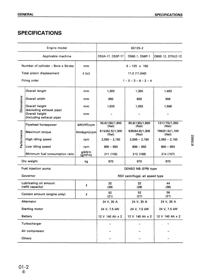
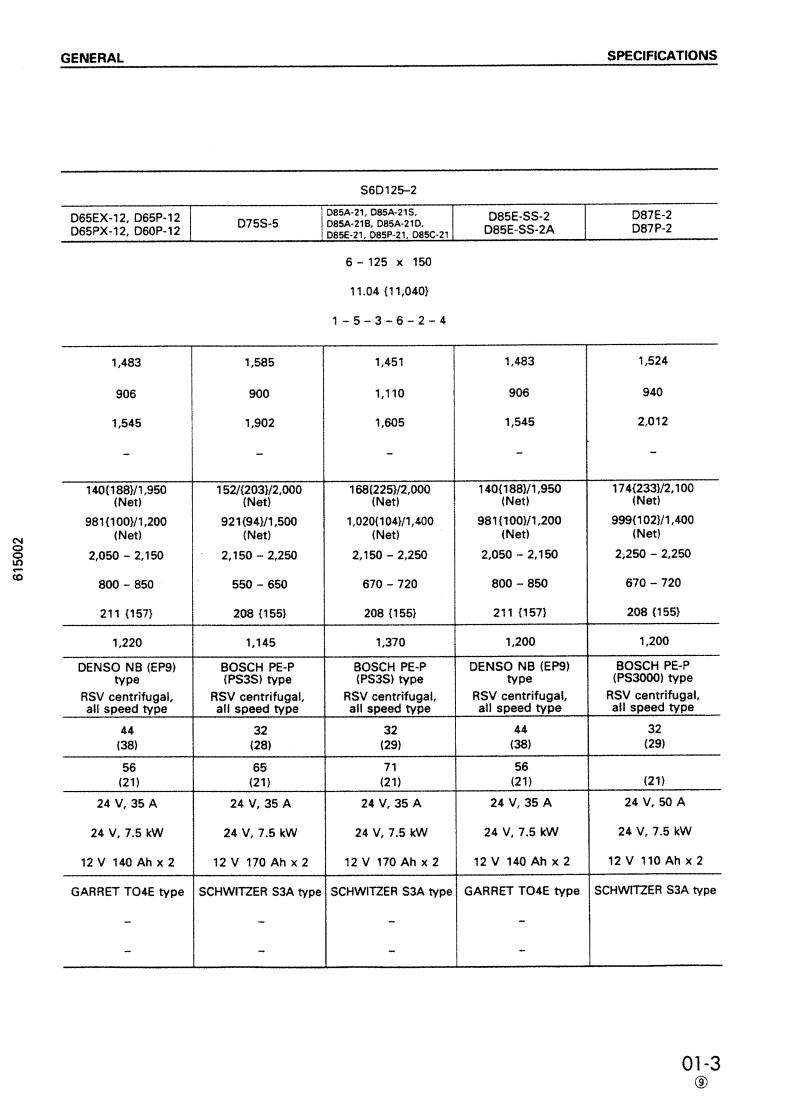
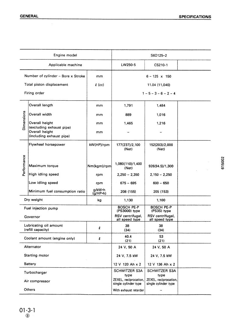 Loading...