

Data Logging and
Remote Control Software
for the XG Series
XG VisionTerminal
96107E
User's Manual
Read this manual before using this system.
Always keep this manual in a safe place
for future reference.
Introduction
Introduction
This manual explains how to install, handle, and operate the data logging and remote control software for
the machine vision system XG Series (XG-8000/XG-7000: herein referred to as the [XG Series], XG
VisionTerminal [herein referred to as XG Vision Terminal]. It also covers precautions regarding use of the
software. Read this manual thoroughly to understand the XG VisionTerminal functions in order to
maximize performance of the system.
Additionally, this manual can be used in conjunction with Ver. 5.∗ for the XG-8000 or Ver.4.∗ for the XG-
7000 but understand that in addition to the restrictions for the specific version that are described as
"notes" there may be slight differences in the screen structure and other such elements when reading this
manual.
Always keep this manual in a safe place for future reference.
Please ensure the manual is passed to the end user of the software.
Related manuals
When using the XG Vision Terminal, read all the various manuals included with the XG Series that will be
used.
Symbols
The following warning symbols are used to ensure safety and to prevent human injury and/or damage to
property when using the system.
DANGER
Indicates that the operator is at risk of death or serious physical injury if the system is improperly
operated or this precaution is not followed.
Warning
Indicates that the operator is at risk of physical injury if the system is improperly operated or this
precaution is not followed.
Caution
Indicates that property could be damaged (product malfunction, etc.) if the system is improperly
operated or this precaution is not followed.
Note
Indicates important operating procedures that could be easily overlooked.
Reference
Indicates items to enhance system understanding and other useful information.
2

Introduction
Trademarks
• Microsoft, Windows, Windows Vista ,and Excel are either registered trademarks or trademarks of
Microsoft Corporation in the United States and/or other countries.
• "SD Memory Card" is a registered trademark of the SD Association.
• Other company names and product names noted in this document are registered trademarks or
trademarks of their respective companies. The ™ mark and ® mark have been omitted in this manual.
3

Introduction
General Cautions
• Before using the XG VisionTerminal to communicate with the XG Series controller, confirm that all
system functions of the XG controller are working properly.
• Before starting or operating the system, check to make sure all system functions are working correctly.
• If the system is operated beyond its published specifications or if the system is modified, its functions
and performance cannot be guaranteed.
• Please note that when the system is used in combination with other devices, its functions and
performance may be negatively affected.
• Do not use the system to protect the human body.
Precautions
• Do not launch more than one instance of the XG VisionTerminal.
4

Software License Agreement
Software License Agreement
NOTICE TO USER: PLEASE READ THIS SOFTWARE LICENSE AGREEMENT ("THIS AGREEMENT")
CAREFULLY. BY USING ALL OR ANY PORTION OF THE XG VisionTerminal ("THIS SOFTWARE"), YOU
ARE AGREEING TO BE BOUND BY ALL THE TERMS AND CONDITONS OF THIS AGREEMENT. IF YOU
DO NOT AGREE TO THE TERMS OF THIS AGREEMENT, DO NOT USE THIS SOFTWARE.
If you install, copy and or use all or a portion of this Software on a device or computer, you will be
deemed to have agreed to all the terms of this Agreement, and this Agreement will come into effect.
1. Definitions
1.1 "Use" or "using" refers to the accessing, installing, downloading, copying, operating and or
otherwise benefiting from the utilization of this Software.
1.2 "This Software" denotes the software and all associated documentation provided by KEYENCE.
1.3 "User" or "User's" infers the company or persons who have had the license to use this Software
granted to them by KEYENCE.
2. Grant of License.
2.1 In compliance with all of the terms and conditions of this Agreement, KEYENCE grants the non-
exclusive and non-transferable license to install and use this Software.
2.2 The granting of the license permits the single reproduction and or copying of this Software for the
User's backing up or archiving purposes.
2.3. This Software maybe installed on multiple devices and computers for the User's benefit and use.
2.4. The transfer of this Software via devices and computers with this Software installed on them by the
User to third parties is permitted. In such a case, the third party who receives this Software may
continue to use this Software in the same manner as the previous User.
2.5. With the transfer of this Software to a third party, the original User may install this Software to
additional devices and computers for further use as required. In such a case, the third party who
receives this Software may continue to use this Software in the same manner as the previous User.
2.6. The User maintains and guarantees that any thirdparties (as detailed in the previous two sections)
who receive and use this Software agree to this license Agreement and comply with all the terms
and conditions.
3. Restrictions.
3.1. This Software may not be modified by the User in any form except from the installation of updates or
new functions provided by KEYENCE.
3.2. The reverse engineering, decompiling or disassembling of this Software by any persons are not
permitted.
3.3. Without the prior permission of KEYENCE, the User may not reproduce or copy this Software for
selling or distributing to a third party
4. Intellectual Property Rights.
Except as stated herein, KEYENCE reserves all rights, titles and interests in this Software, along with all
associated copyrights, trademarks, and other intellectual property rights.
5

Software License Agreement
5. Disclaimer.
This Software is licensed to the User "AS IS" and without any warranty of any kind. In no event does
KEYENCE or its suppliers accept or assume any liability for any damages, claims, costs or profit loss as
a result of operating this Software.
6. Termination.
6.1 Under this Agreement the User's license will automatically terminate if this Software and any
associated copies of this Software are destroyed or voluntarily returned to KEYENCE.
6.2 Under this Agreement the User's license will terminate immediately and automatically without any
notice from KEYENCE if there is any failure to comply with any of the terms and conditions of this
Agreement. Upon termination, the using of this Software shall cease, and all copies (full or partial)
of this Software should be destroyed or returned to KEYENCE.
6.3 Compensation will be sought by KEYENCE should any violation or breach of this Agreement result
in any incurred costs or lost profit to KEYENCE.
7. Governing Law.
7.1 This Agreement will be governed by and construed in accordance with the substantive laws of
Japan.
7.2 If any part of this Agreement is found void and unenforceable, the rest of this Agreement will remain
intact, valid and enforceable according to the associated terms and conditions.
6

Contents
Contents
Introduction .............................................................2
General Cautions ..................................................4
Precautions ...........................................................4
Software License Agreement ..................................5
Contents ..................................................................7
Chapter 1 Introduction
Confirming the Package Contents ...................... 1-1
Overview of the XG VisionTerminal .................... 1-2
System Configuration .......................................... 1-3
System Operating Environment .......................... 1-4
Chapter 2 Preparations
Installing the XG VisionTerminal ......................... 2-1
New Installation from the CD-ROM ....................2-1
Uninstalling the Software ...................................2-3
Downloading and Installing the Latest
Version .........................................................2-3
Starting and Exiting XG VisionTerminal .............. 2-5
Starting XG VisionTerminal ................................2-5
Exiting XG VisionTerminal ..................................2-5
Understanding the Respective Windows ............ 2-6
Basic Window ....................................................2-6
Toolbar ...............................................................2-7
Connecting to the XG Series ............................... 2-8
Before Connecting .............................................2-8
Ethernet (1:1) Connection ..................................2-8
LAN Connection ................................................2-9
USB Connection ..............................................2-10
Chapter 3 Typical Uses
Typical Uses of XG VisionTerminal ..................... 3-1
Controlling the XG Series Remotely
(Remote Desktop) .......................................... 3-2
1. Registering a Controller .................................3-2
2. Connecting to the Controller ..........................3-3
3. Displaying the Remote Desktop ....................3-3
4. Controlling the Remote Desktop ....................3-4
Logging Data from the XG Series ....................... 3-6
1. Registering a Controller .................................3-6
2. Connecting to the Controller ..........................3-7
3. Start Logging .................................................3-7
4. Viewing the Log .............................................3-8
Chapter 4 XG VisionTerminal
Application Menu
XG VisionTerminal Application Menu .................. 4-1
File Menu ............................................................. 4-2
Creating a New Settings File (New) ..................4-2
Opening a Settings File (Open) .........................4-2
Saving the Settings File (Save) ..........................4-2
Saving the Settings File (Save as) ..................... 4-3
Exiting the XG VisionTerminal (Exit) ..................4-3
View Menu ........................................................... 4-4
Show/Hide the Connections view
(Connections) ..............................................4-4
Operating the Remote Desktop
(Show Handheld Controller View) ................ 4-4
Temporarily Disabling Remote Desktop
Operations (Locking Handheld Controller) .. 4-6
Changing the Displayed Contents for Each
Connection ...................................................4-6
Connections Menu .............................................. 4-9
Registering a New Connection
(Add Connection) ........................................4-9
Operation Menu ................................................. 4-10
Connecting to All Registered XG Series
controllers (Connect All) ............................4-10
Disconnecting the Connected XG Series
Controllers (Disconnect All) ....................... 4-10
Starting Logging (Start Logging) .....................4-10
Stopping Logging (Stop Logging) ..................4-10
Window Menu .................................................... 4-11
Switching View Layout in the XG VisionTerminal
Window (Select Layout). ............................4-11
Aligning the Views in the XG VisionTerminal
Window (Arrangement) ..............................4-11
Bringing a View to the front (View Name) ........4-11
Settings Menu ................................................... 4-12
Acquiring a File From a Connected
XG Series Controller (Acquire File) ............ 4-12
Changing the XG VisionTerminal Global
Settings (Options) ......................................4-13
Observing 3D images (3D viewer) ..................4-14
Help Menu ......................................................... 4-16
Displaying the Help File (Help) .......................4-16
Displaying the Version Number of the XG
VisionTerminal (Version Info) .....................4-16
Chapter 5 Appendix
Error Messages ................................................... 5-2
7

Contents
8
Chapter
Introduction
1
Confirming the Package Contents
This package contains the following equipment and
accessories. Check that all accessories are included
before using this system.
V-Works for XG (Integrated Management Software for
the XG Series machine vision system)
(Model Number: XG-H7E or XG-H8NE)
1 x CD-ROM
• This disc contains the installer, program files, and PDF
instruction manual files for the XG VisionTerminal. Keep
this disc in a safe place following installation.
• A backup should be made in case the CD-ROM or case
are accidently damaged.
Note
While we have taken the utmost care in packing these
components, should you find any items missing or damaged,
please notify your nearest KEYENCE sales office.
Introduction
Reference
For details on the contents of the CD-ROM, see the Installation CD
Instructions found in the CD-ROM case.
1-1
Overview of the XG VisionTerminal
Overview of the XG VisionTerminal
The XG VisionTerminal is specifically designed for the
machine vision system XG Series.
Overview
The XG VisionTerminal uses a remote desktop function that
allows you to issue console commands from the PC and
view the monitor output from the XG Series on your PC.
Connection via Ethernet or USB
The XG VisionTerminal also collects image and
measurement data from the XG Series via an Ethernet or
USB connection.
Note
The XG Vision Terminal Ver. 4.* has some items that are
unsupported for log data collection and remote desktop
between it and the XG-8000 Series.
When connecting with XG-8000 Series, use XG
VisionTerminal Ver.5.0 or later, and when using the 3D
viewer (Page 4-14), use XG VisionTerminal Ver.5.3 or later.
Major functions
Remote desktop
The XG VisionTerminal allows you to view the monitor
output from the XG Series on a PC. Not only is it possible to
update and check image output in real time, it is also
possible to operate the XG Series directly with a PC
mouse.
Data acquisition (logging)
The XG VisionTerminal can collect and store inspection
results, images, and archived data output from the XG
Series. A log view provides the most recent results in real
time.
Console input
While using the remote desktop, users can send console
button instructions to the XG Series. In addition to clicking
console buttons visualized on the PC, users can also use a
joypad connected to the PC to send instructions.
File acquisition
The XG VisionTerminal can acquire files from the SD1 or
SD2 card of the XG Series controller containing program
files, global settings, and archived images for storage on
the PC.
1-2
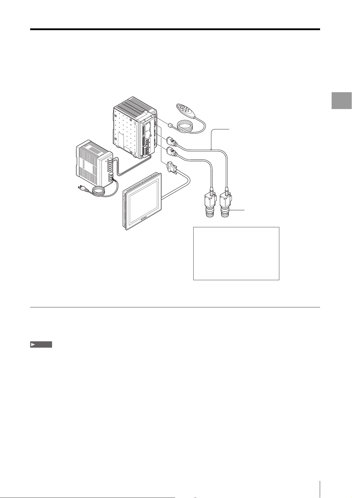
System Configuration
Example of a standard system of XG-7000 Series setup with two cameras using the XG VisionTerminal.
Controller
XG-7700/7500/7000
Handheld Controller
(OP-84231, option)
SD card (OP-87133, 512 MB*)
(Loaded in slot SD1 on controller)
*XG-7700 comes with 1 GB
Camera cable
CA-CN3 (3 m)/
CA-CH3* (3 m) (option)
* Used to connect
high-speed cameras
System Configuration
Introduction
24 V DC power supply
CA-U3 (option)
Monitor
CA-MP81
(option)
Camera 1
Supported
cameras
(option)
Camera 2
XG-200C
XG-S200C
XG-200M
XG-S200M
XG-H100C
XG-H100M
XG-H500C
XG-H500M
Lenses (option)
1
*
/XG-035C
1
*
/XG-S035C
1
*
/XG-035M
1
*
/XG-S035M
1
*
/XG-H035C
1
*
/XG-H035M
2
*
/XG-H200C
2
*
/XG-H200M
*1 XG-7700/7500 only.
*2 XG-7700 only.
Connection cable product numbers
• Ethernet cable (1 Gbps, cross): OP-66843
• USB cable (Ver 2.0): OP-66844
Note
• Ethernet connection supports up to 8 controllers.
• Ethernet and USB connections may be used at the same time, but only one USB connection is allowed.
1
*
1
*
1-3
System Operating Environment
System Operating Environment
The XG VisionTerminal requires a personal computer that meets the following conditions.
Supported OS Microsoft Windows XP Home Edition/Professional SP 2 or later
Microsoft Windows Vista Home Basic, Home Premium, Business, Ultimate, Enterprise
Microsoft Windows 7 Home Premium, Professional, Ultimate, Enterprise
• Supports the 32bit/64-bit version of Microsoft Windows 7 only. For all other operating systems,
only the 32-bit version is supported.
• Operating systems not listed are not supported.
Runtime environment • CPU:
Minimum: Core2Duo (1.06 GHz or faster) or an equivalent processor.
Recommended: Core2Duo (1.80 GHz or faster) or an equivalent processor.
• RAM: 1 GB or more (2 GB or higher for Ver. 5.0 or later).
• HDD: 500 MB or higher available space. *Additional available space is required for storing
images.
• Monitor: 1024 x 768 resolution of higher (1280 x 1024 resolution or higher recommended).
• Optical drive: An optical drive is required to use the installation CD-ROM.
• USB port: USB port must be Ver. 2.0 compatible if using the USB connection.
Note
Only one XG Series controller can be connected to the USB port.
1-4
Chapter
Preparations
Installing the XG VisionTerminal
2
Installation procedures will differ depending on whether
the program is being installed from the CD-ROM or by
downloading from the User Support page.
Reference
This example below explains the installation procedures for
Windows XP.
Preparations
New Installation from the CD-ROM
Install the XG VisionTerminal from the CD-ROM by using
the following procedures.
Note
• If the PC you are installing to does not have the necessary
runtime components used by this software, you will be asked to
install those components. Follow the instructions and install all
components as necessary.
• Do not connect the USB cable to the PC and XG Series
controller prior to installation.
• Installation must be performed by a user with Administrator
privileges.
• Uninstall any previous version of this software (Page 2-3).
• When installing on a notebook PC, be sure to connect the AC
adapter power supply.
1 Insert the XG-H7N or XG-H8N CD-ROM into the CD-
ROM drive of the PC.
The installation guide appears.
Reference
If the installation guide does not appear, double-click
\XG\VisionTerminal\setup.exe located on the CD-ROM.
2 Click [Install XG VisionTerminal Ver.[the version the
will be installed]].
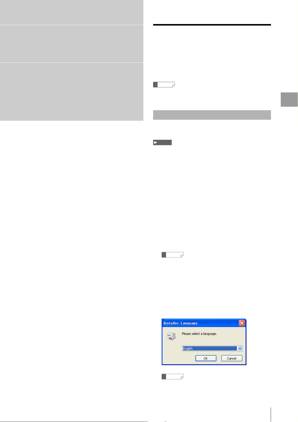
The installer launches and the [Installer Language]
appears.
Reference
If the installer does not appear, double-click setup.exe in the
CD-ROM menu.
2-1
Installing the XG VisionTerminal
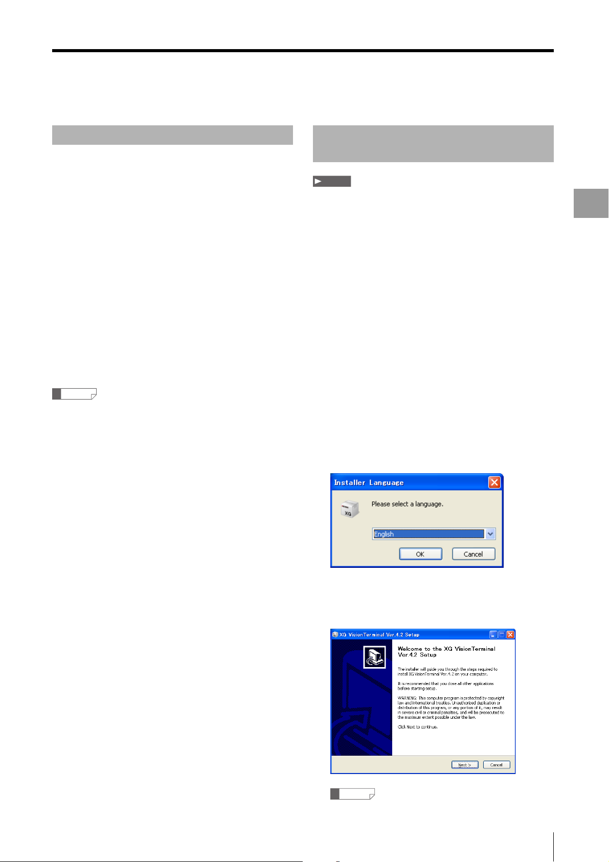
3 Select language and click [OK].
[Setup Wizard for XG VisionTerminal] appears.
Reference
The version number will differ depending on the model and
period when purchased.
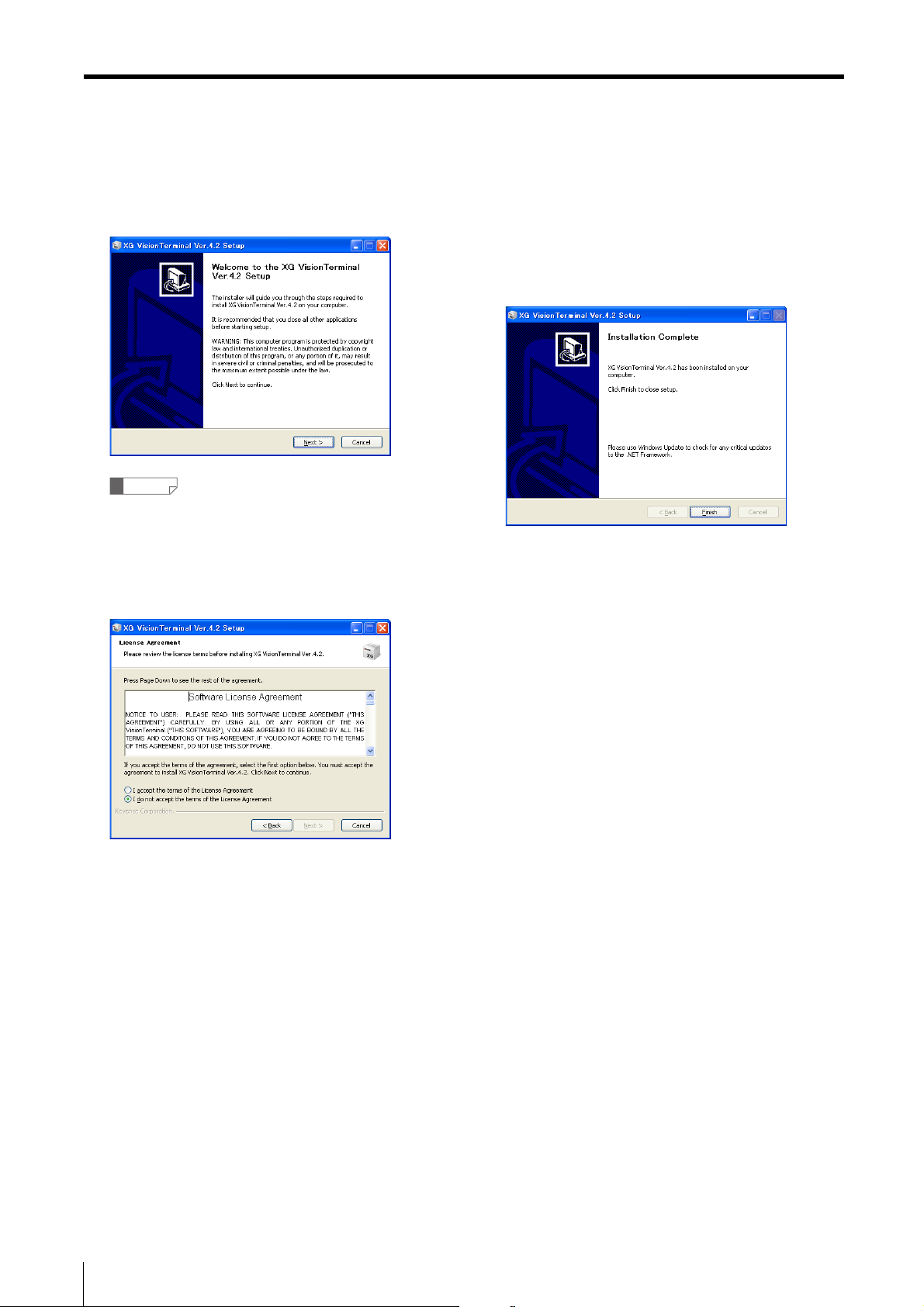
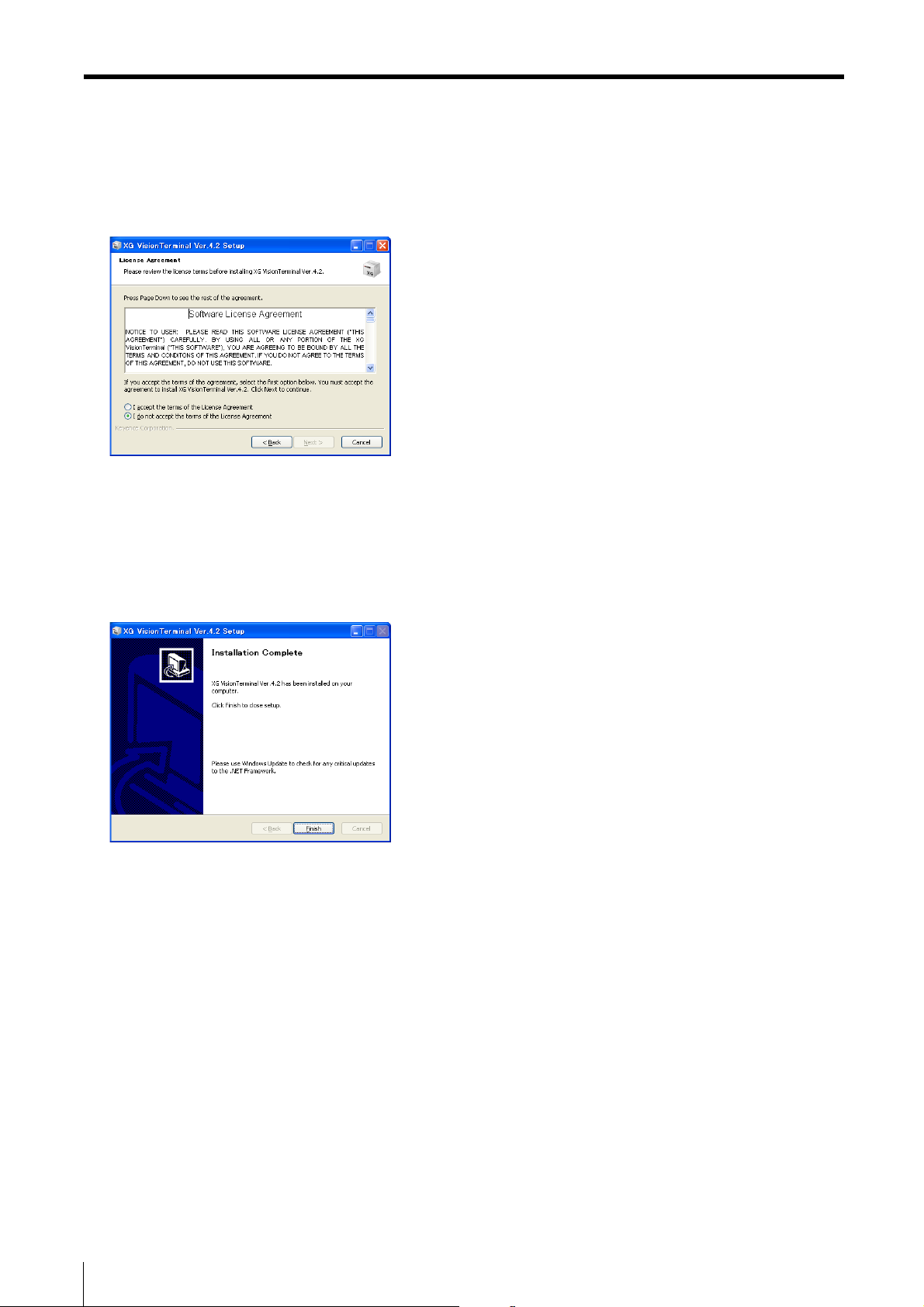
4 Click [Next].
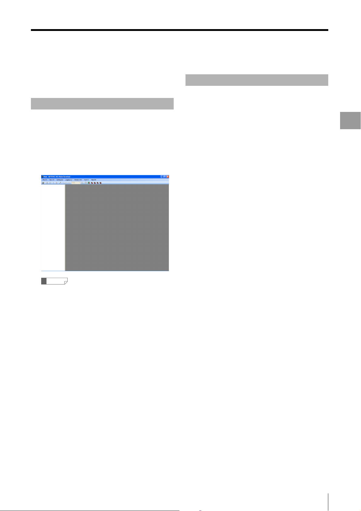
The [User License Agreement] appears.
5 Follow the on-screen instructions to complete the
installation.
6 When the [Installation completed] menu appears,
click [Finish].
The XG VisionTerminal installation is completed.
• The shortcut icon for the [XG VisionTerminal Ver. ∗.∗]
appears on the desktop.
• A shortcut will be added to the Windows Start menu under
KEYENCE Applications → V-Works for XG Ver. ∗.∗ → XG
VisionTerminal Ver. ∗.∗.
2-2
Installing the XG VisionTerminal
Uninstalling the Software Downloading and Installing the
Uninstall the XG VisionTerminal using [Add/Remove
Programs] in the Windows Control Panel.
1 Click the Start menu and select [Control Panel].
The [Control Panel] appears.
2 Double-click the [Add/Remove Programs] icon.
The [Add/Remove Programs] menu appears.
Latest Version
Note
• If the PC you are installing to does not have the necessary
runtime components used by this software, you will be asked to
install those components. Follow the instructions and install all
components.
• Do not connect the USB cable to the PC and XG Series prior to
installation.
• Installation must be performed by a user with Administrator
privileges.
Preparations
3 Select [XG VisionTerminal Ver. ∗.∗] and click
[Remove].
A confirmation screen appears.
4 Click [Yes].
The XG VisionTerminal is removed.
Reference
If asked to confirm whether to delete shared files, click [Yes] to
remove all files.
1 Uninstall any previous version of the XG
VisionTerminal.
2 Download the latest files from the User Support
page.
XG Series Users Support page
http://www.keyence.com.sg/support/index.php
3 Double-click the downloaded file.
The installer launches and the [Installer Language]
appears.
4 Select language and click [OK].
[Setup Wizard for XG VisionTerminal] appears.
Reference
The version number will differ depending on the model and
period when purchased.
2-3
Installing the XG VisionTerminal
5 Click [Next].
The [User License Agreement] appears.
6 Follow the on-screen instructions to complete the
installation.
7 When the [Installation completed] menu appears,
click [Finish].
The XG VisionTerminal installation is completed.
• The shortcut icon for the [XG VisionTerminal Ver. ∗.∗]
appears on the desktop.
• A shortcut will be added to the Windows Start menu under
KEYENCE Applications → V-Works for XG Ver. ∗.∗ → XG
VisionTerminal Ver. ∗.∗.
2-4
Starting and Exiting XG VisionTerminal
Starting and Exiting XG VisionTerminal
This section explains how to start and exit the XG
VisionTerminal.
Starting XG VisionTerminal
Click the shortcut in the Windows Start menu under
All Programs → KEYENCE Applications → V-Work s
for XG Ver. ∗.∗ → XG VisionTerminal Ver. ∗.∗.
Or, double-click the shortcut icon for the [XG
VisionTerminal Ver.
The initial window appears.
∗.∗] on the desktop.
Exiting XG VisionTerminal
Click [File], and then [Exit].
Or, click the close button at the upper right of the
window.
The XG VisionTerminal exits.
Preparations
Reference
• After the XG VisionTerminal has been launched for the first
time, it will automatically load the last saved settings files.
• If [Automatic connection on startup] and [Start logging on
startup] are selected in the [Options] menu (Page 4-13),
the XG VisionTerminal will automatically begin logging the
next time it is started.
2-5
Understanding the Respective Windows
Understanding the Respective Windows
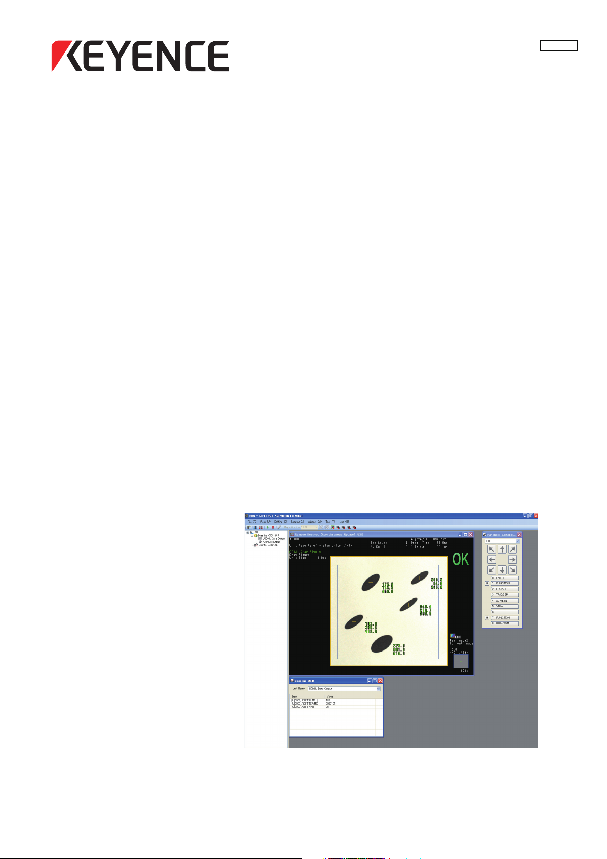
(5) Remote desktop
Basic Window
The basic window for the XG VisionTerminal is outlined
below.
(1) (3)(2)
This view shows monitor output from the connected XG
Series controller. See "Controlling the XG Series Remotely
(Remote Desktop)" (Page 3-2) for more details.
(1) Controller view
This view displays the name of the XG Series controllers
that the XG VisionTerminal is connected to, as well as
logging information and a remote desktop operation menu.
(2) Menu bar
This bar displays the menus for executing commands. See
"XG VisionTerminal Application Menu" (Page 4-1) for more
details.
(3) Toolbar
This bar contains button icons for the major commands.
Clicking an icon executes the command. See "Toolbar"
(Page 2-7) for more details.
(4) Log Summary view
This view shows the most recent data as it is being logged.
See "Viewing logs (Log Summary)" (Page 4-6) for more
details.
(6) Handheld controller view
This view allows you to operate the handheld controller
from the XG VisionTerminal while displaying the remote
desktop view. See "Operating the Remote Desktop (Show
Handheld Controller View)" (Page 4-4) for more details.
2-6
(7) 3D viewer
By using information acquired from the 3D camera or LJ-V,
the 3D image of object for the inspection is displayed
(supported by XG VisionTerminal Ver.5.3 or later versions).
See "Observing 3D images (3D viewer)" (Page 4-14) for
more details.

Understanding the Respective Windows
Toolbar
The most frequently used functions and settings in the XG
VisionTerminal can be accessed by clicking these icons on
the toolbar.
Icons and names
on the toolbar
Add
Connection
Connect All
Disconnect
All
Start
Logging
Stop
Logging
Options
Zoom Ratio
(%)
Auto-fit
Update
Remote
Desktop
View
Layouts 1 to
5
Functions
Registers a XG Series controller
connection to log data from and to the
monitor using the remote desktop
function in the XG VisionTerminal. See
"Connecting to the XG Series" (Page 2-
8) for more details.
Connection to all registered XG Series
controllers begins. See "Connecting to
All Registered XG Series controllers
(Connect All)" (Page 4-10) for more
details.
Disconnects all connected XG Series
controllers. See "Disconnecting the
Connected XG Series Controllers
(Disconnect All)" (Page 4-10) for more
details.
Logging from all connected XG Series
controllers begins. See "Starting
Logging (Start Logging)" (Page 4-10)
for more details.
Logging from all XG Series controllers
for which logging is in progress stops.
See "Stopping Logging (Stop Logging)"
(Page 4-10) for more details.
Changes the XG VisionTerminal global
settings. Displays the [Options] menu.
See "Changing the XG VisionTerminal
Global Settings (Options)" (Page 4-13)
for more details.
Changes the zoom ratio of the remote
desktop window.
Automatically adjusts the zoom ratio of
the remote desktop to fit the window
size of the XG VisionTerminal.
Manually update the remote desktop
display. See "Switching the update
method for the remote desktop" (Page
4-7) for more details.
Switches through each view layout of
the XG VisionTerminal window. See
"Switching View Layout in the XG
VisionTerminal Window (Select Layout)."
(Page 4-11) for more details.
Icons and names
on the toolbar
3D viewer
Functions
By using information acquired from the
3D camera or LJ-V, the 3D image of
object for the inspection is displayed
(supported by XG VisionTerminal
Ver.5.3 or later versions). See
"Observing 3D images (3D viewer)"
(Page 4-14) for more details.
Preparations
2-7

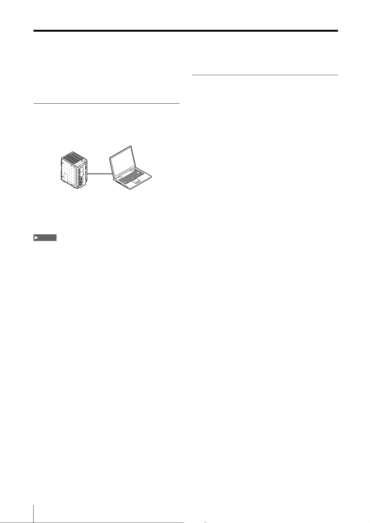
Connecting to the XG Series
Connecting to the XG Series
After connecting the PC with XG VisionTerminal installed
and a XG Series controller, the controller must be
registered as the connection.
Before Connecting
Check the following settings.
Settings on the PC
Set the information required for the Ethernet connection (IP
address, Subnet mask, Port number, etc.). For more
details, see the PC and XG Series manuals.
Ethernet (1:1) Connection
Connect the XG Series directly to the PC using an Ethernet
cable (cross cable: OP-66843).
Ethernet connection
Settings on the XG Series
Start up the XG Series controller and verify the Ethernet
settings are correct. For details, see the user manual for
the XG series that will be used.
Connecting to the XG Series
Connect the Ethernet cable (cross cable: OP-66843) to
the Ethernet ports on the XG Series controller and the
PC.
Registering the XG Series in the XG
VisionTerminal
The XG Series must be registered as a connection so that
the XG VisionTerminal can recognize it.
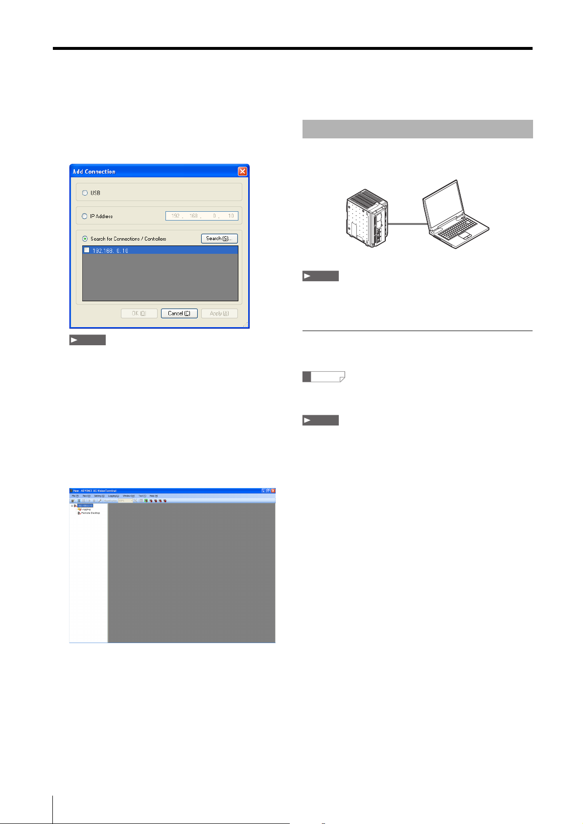
1 From the [Connections] menu, click [Add Connection].
The [Add Connection] menu appears.
2-8
2 Select [Search for Connections/Controllers].

3 Click [Search].
The XG Series connected to the PC appears in the list.
Connecting to the XG Series
LAN Connection
Connect the XG Series and PC over an Ethernet-based
LAN.
Preparations
HUB
(Router)
Note
• Clicking [Search] will only display controllers that exist in
the same subnet.
• The controller may not show up initially if there are multiple
controllers on the network. In this case, repeat the search a
few times.
4 Check the box next to the XG Series controller to
register it as a connection and click [OK].
The new connection is added and appears in the
system view.
Connecting to the XG Series
Connect the Ethernet cable (commercial straight
cable) to the Ethernet ports on the XG Series
controller and a hub or LAN port device.
Registering the XG Series in XG
VisionTerminal
The XG Series must be registered as a connection so that
the XG VisionTerminal can recognize it.
1 From the [Connections] menu, click [Add Connection].
The [Add Connection] menu appears.
2 Select [Search for Connections/Controllers].
2-9
Connecting to the XG Series
3 Click [Search].
The XG Series controllers that are connected on the
LAN appear in the list.
USB Connection
Connect the XG Series directly to the PC using a USB
cable.
USB connection
Note
The XG VisionTerminal and XG VisionEditor cannot connect over
the USB cable simultaneously.
Note
• Clicking [Search] will only display controllers that exist in
the same subnet.
• When there are multiple controllers connected to the
network, some of them may not show up initially. Repeat
the search as necessary.
4 Check the box next to the XG Series controller to
register it as a connection and click [OK].
The new connection is added and appears in the
system view.
Installing the driver
Connect the XG Series and PC and install the driver.
Reference
The driver installation is not required if the USB driver was already
installed for the XG VisionEditor.
Note
• The installation wizard does not appear on Windows 7. To
install on Windows 7, connect the system and the PC, then use
Device Manager to manually install the USB driver.
In Device Manager, click [Update driver] on the property page
for the [XG-8000/7000 Series] under [Other devices], and
specify the folder that contains the USB driver.
• The USB driver is stored in \driver\USB in the enclosed
CDROM. Note, this driver is also installed in the
[c:\drivers\VWorks for XG] (For Ver. 5.∗, c:\drivers\V-Works for
XG H8N) following installation of the XG VisionTerminal.
• When using Windows 7 64-bit version, execute dpinst.exe
located in \drivers\USB\x64\ in the enclosed CDROM and then
install the USB driver.
2-10

Connecting to the XG Series
1 Connect the XG Series to the PC using the optional
USB cable (OP-66844).
[Found New Hardware Wizard] will appear on the PC
screen.
2 Select "No, not this time", and click [Next].
3 Select [Install from the list or specified location]
and specify the folder that contains the USB driver.
Installation of the USB driver starts.
Reference
• The USB driver is stored in \driver\USB in the enclosed CD-
ROM. Note, this driver is also installed in the [c:\drivers\V-
Works for XG] (For Ver. 5.∗, c:\drivers\V-Works for XG H8N)
following installation of the XG VisionTerminal.
• When you install a driver in the Windows XP environment,
Windows may display a warning message. When a
warning message appears, click [Continue] to complete
the driver installation.
Registering the XG Series in the XG
VisionTerminal
The XG Series must be registered as a connection so that
the XG VisionTerminal can recognize it.
Note
Only one XG Series can be registered as a USB connection.
1 From the [Connections] menu, click [Add Connection].
The [Add Connection] menu appears.
2 Click [USB].
3 Click [OK].
The new connection is added and appears in the
system view.
Preparations
4 When the USB driver installation is completed,
click [Finish].
The XG Series and PC are now connected through the
USB.
2-11

Connecting to the XG Series
2-12

Chapter
Typical Uses
Typical Uses of XG VisionTerminal
3
This Chapter explains the operations outlined below used
to accomplish basic tasks in the XG VisionTerminal.
• Controlling the XG Series remotely (remote desktop)
(Page 3-2).
• Logging data from the XG Series (Page 3-6).
Reference
To utilize the other features available in the XG VisionTerminal, see
"XG VisionTerminal Application Menu" (Page 4-1).
Typical Uses
3-1

Controlling the XG Series Remotely (Remote Desktop)
Controlling the XG Series Remotely
(Remote Desktop)
View the monitor output from the XG Series controller in XG
VisionTerminal.
Note
XGA image output is not supported in Ver. 4.∗.∗∗∗.
1. Registering a Controller
Register the XG Series controller as a connection in the XG
VisionTerminal to view the screen output.
1 From the [Connections] menu, click [Add
Connection].
The [Add Connection] menu appears.
3 Click [OK].
The new connection is added and appears in the
system view.
2 Specify the XG Series controller to register it as a
connection.
For a USB connection
Click [USB].
For an Ethernet connection
Select [Search for Connections/Controllers], and then
click [Search]. The XG Series connected to the PC
appears in the list. Check the box next to the XG
Series controller you wish to register as a connection.
Note
• Clicking [Search] will only display controllers that exist in
the same subnet.
• When there are multiple controllers connected to the
network, some of them may not show up initially. Repeat
the search as necessary.
Reference
To register an XG Series controller that does not display as
connected to the network after searching, select [IP Address]
and manually enter the IP address.
3-2

Controlling the XG Series Remotely (Remote Desktop)
2. Connecting to the Controller 3. Displaying the Remote Desktop
This procedure connects the XG Series controllers that are
registered as connections in the XG VisionTerminal.
Click [Connect All] from the [Operation] menu.
When the connection is completed, icons for each
connection in the system view change from to
.
Reference
You can also connect to the controllers by clicking icon on
the toolbar.
Note
• If any of the connections fail, a confirmation screen will appear.
• When multiple connections are registered, it is not possible
select individual controllers to connect to, all of them will be
connected.
• The XG VisionTerminal and XG VisionEditor cannot connect
over the USB cable simultaneously.
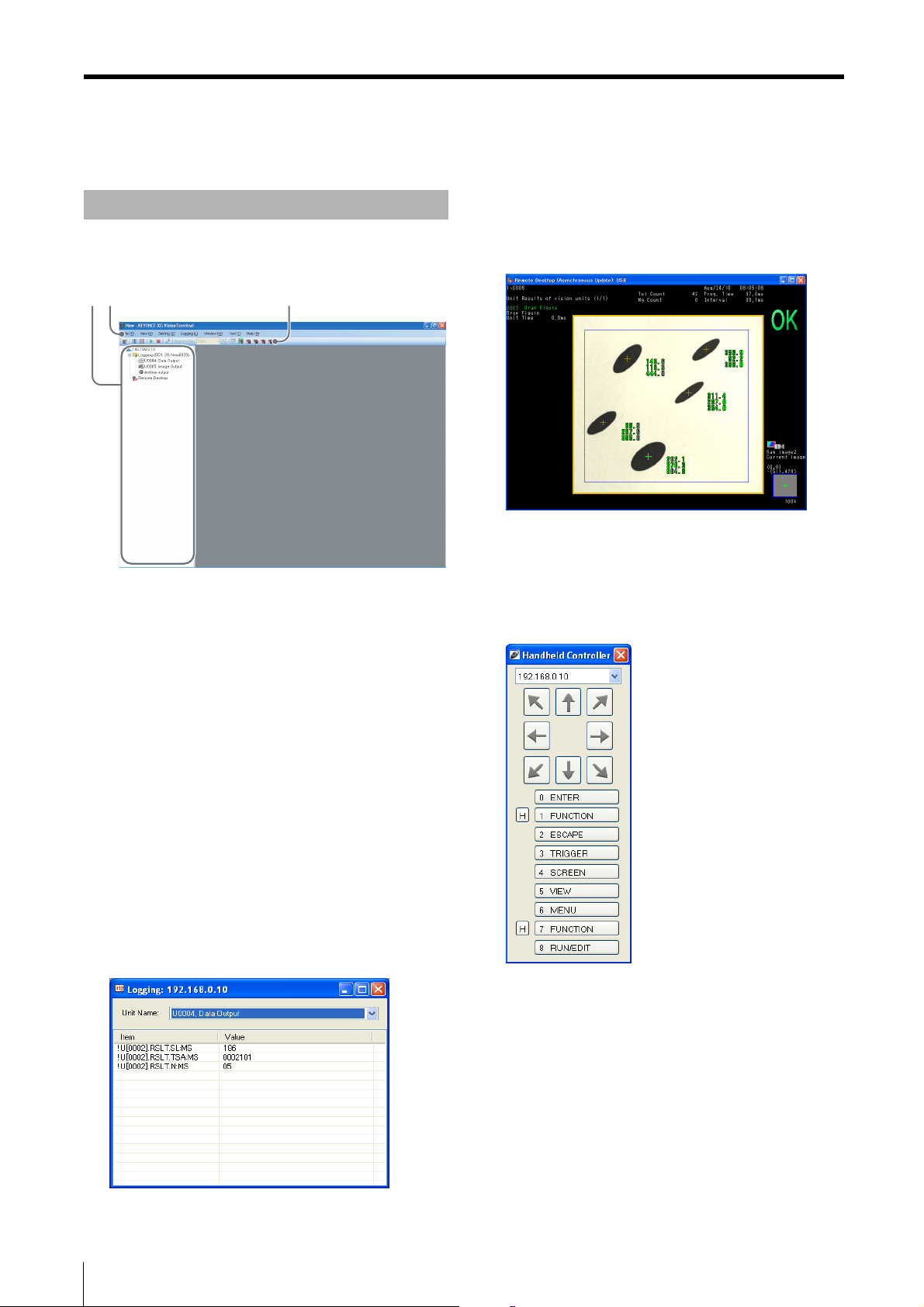
This procedure displays the monitor output from the
connected XG Series controller.
Note
XGA image output is not supported in Ver. 4.∗.∗∗∗.
1 From the [View] menu, select the desired XG series
connection and then click [Launch Remote
Desktop].
The remote desktop window appears.
Typical Uses
Note
If you select [Launch Remote Desktop] from the XG
VisionTerminal for a controller already displayed in a remote
desktop window in the XG VisionEditor, operations for that
remote desktop will take priority.
2 If required, you can change how the remote
desktop screen is updated. To do this, click the
[View] menu - and select the desired connection
and change the screen update method.
There are three methods available for updating the
remote desktop. Choose the method based on the
operating conditions of the XG Series connected and/
or the PC running XG VisionTerminal.
• Asynchronous: Updates at regular intervals.
Continuous: Updates in real time.
•
•
Manual: Updates by clicking [Update] under the [View]
menu for the selected connection.
3-3

Controlling the XG Series Remotely (Remote Desktop)
Reference
• Displaying remote desktops for multiple controllers using
[Continuous] may result in slow screen updates for all
connected XG Series controllers. In this case, select
[Asynchronous].
• The update interval for [Asynchronous] cannot be user
specified to an arbitrary value because the interval is
determined automatically based on the current connection
status.
• A check mark will appear next to the selected update method
when the menu is displayed.
• You can also specify the update method from the shortcut
menu displayed by right-clicking on the remote desktop
window.
• The remote desktop icon for connections in the system view will
reflect the update method selected.
- : asynchronous or continuous
- : manual
Closing the remote desktop
Click the close button on the upper right side of the remote
desktop window.
4. Controlling the Remote Desktop
Sending remote console keystrokes
This procedure displays the console view for operating the
XG Series controller currently displayed in the remote
desktop window.
In addition to sending remote console keystrokes by
clicking buttons visualized in the console view, users can
also use the keyboard or joypad connected to the PC.
1 From the [View] menu, click [Handheld Controller].
The [Handheld Controller] window appears.
3-4
Reference
You can also display the handheld controller view by clicking
[Handheld Controller] in the shortcut menu displayed by
right-clicking on the remote desktop window.
2 Operation using the handheld controller window.
Targ et
Select the XG Series controller to operate from the
drop down list.
Cursor button
Click to move through the screen as the 8-way button
does on the handheld controller.
Buttons 0 to 8
Click to execute the same action assigned to the
button on the handheld controller.
Functions assigned to each button number are listed
to the right of the number.

Controlling the XG Series Remotely (Remote Desktop)
H button
This button is used to enter multiple key combinations.
Click the H button next to buttons 1 or 7 then click the
other button in the key combination to simulate the key
combination on the handheld controller.
Reference
• You can also send keystrokes using the keyboard or joypad.
The button assignments can be set in the [Options] menu
(Page 4-13).
• The console view must be displayed to enter keystrokes from
the keyboard.
• If multiple remote desktop windows are open, you can change
the operating target for the handheld controller window as
follows.
- Select the operating target from the drop down list at the top
of the handheld controller window.
- From the [View] menu, select the desired connection and
click [Handheld controller].
- The active connection in the handheld controller window is
indicated by a check mark next to the remote desktop
icon in the system view.
Closing the handheld controller window
Click the close button on the upper right of the handheld
controller window.
Operating with a mouse
Mouse control can be used for most of the operations of
the XG Series currently monitored in the remote desktop.
The main operations are as follows.
• Selecting items: Use the mouse to click the button that you
wish to select on the remote desktop.
• Displaying the function menu: Right click with the mouse on
the remote desktop.
• Displaying the touch menu: Use the mouse the click areas
that are not displayed on the remote desktop (Ver. 4.1 or later
controller only).
• Closing the screen: Click (Close), displayed in the upper-
right corner of the screen that you wish to close.
Saving the remote desktop screen to a file
(Capture screen)
This procedure saves the contents of the currently
displayed remote desktop as an image file.
From the [View] menu, select the connected controller
and then click [Capture Screen].
The image shown in the current remote desktop will be
saved to a 24-bit bitmap image file (.bmp) on the PC.
The file will be stored in the [Capture] folder located
under the path set in the [Save file to this base path]
field on the [Options] menu (Page 4-13).
Typical Uses
Reference
• You can also save the remote desktop by clicking [Capture
screen] in the shortcut menu displayed by right-clicking on the
remote desktop window.
• The destination folder can be changed in the [Downloaded File
Basepath] field in the [Options] menu.
3-5

Logging Data from the XG Series
Logging Data from the XG Series
The XG VisionTerminal can log (collect) inspection results,
images, and archived data output from the XG Series
during operation.
Note
• To log data, the flowchart program created in XG VisionEditor
must include either a data output step, an output image step, or
an archived output location step that specifies the [PC
program] as the destination device. For more details, see the
XG VisionEditor Reference Manual (Programming Edition).
• To store images and archived data output from the XG-8000
Series as logs, Ver. 5.0 or higher is required.
1. Registering a Controller
Register the XG Series controller as a connection in the XG
VisionTerminal to log data from it.
1 From the [Connections] menu, click [Add
Connection].
The [Add Connection] menu appears.
2 Specify the XG Series controller to register it as a
connection.
For a USB connection
Click [USB].
For an Ethernet connection
Select [Search for Connections/Controllers], and click
[Search]. The XG Series connected to the PC appears
in the list. Check the box next to the XG Series
controller you wish to register as a connection.
Note
• Clicking [Search] will only display controllers that exist in
the same subnet.
• When there are multiple controllers connected to the
network, some of them may not show up initially. Repeat
the search as necessary.
Reference
To register an XG Series controller that does not display as
connected to the network after searching, click [IP Address]
and manually enter the IP address.
3 Click [OK].
The new connection is added and appears in the
system view.
3-6

Logging Data from the XG Series
2. Connecting to the Controller
This procedure connects the XG Series controllers that are
registered as connections in the XG VisionTerminal.
Click [Connect All] from the [Operation] menu.
When the connection is completed, icons for each
connection in the system view will change from
to .
Reference
You can also connect to the controllers by clicking on the
toolbar.
Note
• If any of the connections fail, a confirmation screen will appear.
• When multiple connections are registered, it is not possible
select individual controllers to connect to, all of them will be
connected.
3. Start Logging
This procedure starts logging data from the XG Series
connected and enabled as a logging target.
From the [Operation] menu, click [Start Logging].
Logging starts and the logging icon in the system view
changes from to .
Clicking on the [+] to the left of the logging icon
expands the logging targets.
Log file destination
Log files are output to [Documents\KEYENCE\XG
VisionTerminal\(IP address or [USB]] (by default) for the
user currently logged in.
Example:
If the destination folder in the data output step
programmed in XG VisionEditor is set to [SD2:\xg\result\],
the default log destination will noted as follows.
• For Windows versions other than Vista/7:
C:\Documents and Settings\name of logged in user\My
Documents\KEYENCE\XG VisionTerminal\(IP address or
[USB])\SD2\xg\result
• For Windows Vista/7:
C:\Users\name of logged in user\Documents\
KEYENCE\XG VisionTerminal\(IP address or
[USB])\SD2\xg\result
Reference
• The logging destination can be changed in the [Downloaded
File Basepath] field. See "Changing the XG VisionTerminal
Global Settings (Options)" (Page 4-13) for more details.
• The log file destination folder can be opened directly by
clicking [Open destination] in the properties menu displayed
by right-clicking on each logging icon, or by double-clicking
the icon. When archiving is in progress, this shortcut always
opens the following location.
- For Windows versions other than Vista/7:
C:\Documents and Settings\name of logged in user\My
Documents\KEYENCE\XG VisionTerminal\(IP address or
[USB]).
- For Windows Vista/7:
C:\Users\name of logged in user\Documents\KEYENCE\XG
VisionTerminal\(IP address or [USB]).
Typical Uses
3-7

Logging Data from the XG Series
4. Viewing the Log
This procedure opens the log summary which displays the
latest data as it is being logged.
Reference
• Up to 32 log views can be displayed at one time.
• The log summary only displays the output results.
1 From the [View] menu, click the [(XG Series
controller to operate)] and then [Show log view].
The [Log Summary] appears.
2 Select the data output step for the log you wish to
view from the [Unit Name] box.
The most recent log data of the selected data output
unit appears in the menu.
Understanding the log view
• Unit name: Select the data output unit for the log you
wish to view.
Log display: The most recently logged items and values
•
for the selected output unit will be displayed.
Note
The display updates may be delayed if multiple log summary
windows are open.
Closing the log summary
Click the close button on the upper right corner of the log
summary window.
3-8

Chapter
4
XG VisionTerminal Application Menu
XG VisionTerminal
Application Menu
Commands in the XG VisionTerminal are organized under
the following seven menus.
• File (Page 4-2)
• View (Page 4-4)
• Connections (Page 4-9)
• Operation (Page 4-10)
• Window (Page 4-11)
• Settings (Page 4-12)
• Help (Page 4-16)
Note
The commands available depend on the type of window being
displayed.
XG VisionTerminal Application Menu
4-1

File Menu
File Menu
This section explains the commands in the [File] menu.
Creating a New Settings File (New)
This command creates a new settings file for the XG
VisionTerminal.
1 From the [File] menu, click [New].
A confirmation screen to save your changes appears.
Reference
If clicking [New] is the very first operation performed after the
XG VisionTerminal starts, the confirmation screen will not
appear (and those steps following 2 are not required).
2 Clicking [Yes] opens up the [Save as] menu.
Reference
• If you click [No] on the confirmation screen, any changes
to the current settings will not be saved and a new file will
be created.
• Clicking [Cancel] will not create any new files.
Opening a Settings File (Open)
This command opens an existing settings file.
1 From the [File] menu, click [Open].
The [Open file] menu appears.
If the currently open file has unsaved changes
A confirmation screen appears. To save the settings,
click [Yes]. Otherwise click [No].
2 Select the settings file and click [Open].
All XG VisionTerminal windows open at this point are
closed, and then a new XG VisionTerminal window
opens under a new settings file.
Saving the Settings File (Save)
This command will save the settings to the current file
overwriting the previous file.
3 Enter the file name, then click [Save].
All XG VisionTerminal windows open at this point are
saved together with the specified settings file, and
then a new XG VisionTerminal window opens under a
new settings file.
Reference
The settings file contains the following information.
• List of XG Series controllers registered as connections in the
XG VisionTerminal.
• View layout information.
• Settings on the [Options] menu (Page 4-13).
• The folder path of the controller for the last list acquired using
the acquire files command (Page 4-12).
• Window size and display position of the XG VisionTerminal.
• Logging targets.
From the [File] menu, click [Save].
This command overwrites the settings file that is
currently open.
Reference
If the settings file is being saved for the first time, the [Save as]
menu appears instead.
4-2

Saving the Settings File (Save as)
This command saves the settings file currently open to a
file with a different name.
1 From the [File] menu, click [Save as].
The [Save as] menu appears.
2 Enter the file name, then click [Save].
The file is saved as a [Settings file] with the extension
".xgn".
Exiting the XG VisionTerminal (Exit)
File Menu
XG VisionTerminal Application Menu
This command exits the XG VisionTerminal.
From the [File] menu, click [Exit].
The XG VisionTerminal exits. If there are any unsaved
changes, a confirmation screen to save the changes
will appear. Click [OK] to save the changes, [No] to
disregard changes and exit, or [Cancel] to return to
VisionTerminal.
4-3

View Menu
View Menu
This section explains the commands in the [View] menu.
Show/Hide the Connections view (Connections)
The connections view is displayed when a check mark
appears next to this command.
With the check mark visible, open the [View] menu
and click [Connections].
This hides the connections view.
Reference
By default, a check mark appears next to this command and the
connections view is displayed.
To show the connection view again
From the [View] menu, click [Connections] again to restore
the check mark.
Operating the Remote Desktop (Show Handheld Controller View)
This command shows the handheld controller view which
is used to operate the XG Series controller currently
monitored in the remote desktop.
In addition to sending remote console keystrokes by
clicking buttons visualized in the handheld controller view,
users can also use the keyboard or joypad connected to
the PC.
From the [View] menu, click [Handheld Controller].
The [Handheld Controller] appears.
Closing the handheld controller view
Click the close button on the handheld controller view.
4-4

View Menu
Using the handheld controller view
Targ et
Select the connected XG Series to operate.
Arrow buttons
Clicking the arrow buttons navigates through the screen in
the same way the 8 way button on the handheld controller
does.
Buttons 0 to 8
These buttons perform the same function as the 0 to 8
buttons on the handheld controller.
Functions assigned to each button number are listed to the
right of the number.
H button
This button is used to enter key combinations with the
function key.
Click the H button next to buttons 1 or 7 then click the other
button to simulate the key combination on the handheld
controller.
Reference
• You can also send keystrokes using the keyboard or joypad. To
do this, change the button assignments in the [Options] menu
(Page 4-13).
• If multiple remote desktop windows are open, you can change
the operating target for the console view as follows.
- Select the operating target from the drop down list at the top
of the console view.
- From the [View] menu, click the [(XG Series controller to
operate)] and then [Capture console operation focus].
Button numbers for each input device
Button numbers on the console
Each button on the console corresponds to the numbers
shown below.
(7)
(0)
FUNCTION TRIGGER
(1)
(4)
ESCAPE
SCREEN MENU
VIEW
(5)
Button numbers when using a joypad
Each button on the joypad corresponds to the numbers
shown below by default (example using an Elecom joypad
JC-U2410TBK).
(8)
(3)
(6)
(2)
(0)
(5)
(2)
(3)
(7)
XG VisionTerminal Application Menu
(6)
(5)
(4)
(1)
USB joypads tested by KEYENCE
• Elecom:
Model: JC-U241-TBK
• Sanwa Supply:
Model: JY-P68US
• Logicool:
Model: GPX-200
Note
Other joypads that have not been tested by KEYENCE may not
function correctly.
4-5

View Menu
Temporarily Disabling Remote Desktop Operations (Locking Handheld Controller)
This command temporarily disables input from the remote
desktop using the handheld controller view to prevent
unintentional operation.
From the [View] menu, click [Lock Handheld
Controller].
"Locked" will appear in the handheld controller view's
title bar and the buttons will be grayed out.
To unlock the handheld controller
From the [View] menu, click [Unlock Handheld Controller].
Note
Closing the handheld controller view will also unlock it as well.
Changing the Displayed Contents for Each Connection
The sub menu located within each connection under the
[View] menu allows the you to change the information
displayed for each connection.
Viewing logs (Log Summary)
This command opens a log summary view that displays
the latest data as it is being logged.
Reference
Up to 32 log summary views can be displayed at once.
1 From the [View] menu, select the desired controller
connection and then click [Log Summary].
The [Log Summary view] appears.
4-6
2 Select the data output step for the log you wish to
view from the [Unit Name] box.
The log for the selected data output unit appears in
the menu.
Closing the log summary view
Click the close button on the log summary view.
Understanding the log summary view
• Unit name: Select the data output unit for the log you
wish to view.
• Log Summary display: The latest value for each item of
the selected data output unit being logged will be
displayed.

View Menu
Monitoring the XG Series remotely (View
remote desktop)
This procedure displays the screen output from the
connected XG Series controller.
Note
XGA image output is not supported in Ver. 4.∗.∗∗∗.
From the [View] menu, select the controller connection
to operate and click [Launch Remote Desktop].
The remote desktop appears.
Saving the remote desktop screen to a file
(Screen Capture)
This procedure saves the contents of the currently
displayed remote desktop screen as an image file.
From the [View] menu, select the controller
connection and then click on [Screen Capture].
The image shown in the current remote desktop will be
saved to a 24-bit bitmap image file (.bmp) on the PC.
The file will be stored in the [Capture] folder located
under the path set in the [Downloaded File Basepath]
field in the [Options] menu (Page 4-13).
Reference
• The destination folder can be changed in the [Options] menu.
• The captured image file will be named as follows: "controller
name_year-month-date_hour-min-sec.bmp".
Changing the target in handheld controller
view
XG VisionTerminal Application Menu
Closing the remote desktop
Click the close button on the remote desktop window.
Switching the update method for the
remote desktop
Change the update method based on the processing load
of the XG Series connections and the PC that is running
the XG VisionTerminal.
From the [View] menu, select the XG Series
connection and then select the desired update
method.
The following three update methods are available.
• Asynchronous: Updates at regular intervals.
Continuous: Updates in real time.
•
Manual: Updates manually by clicking [Update] under
•
the controller connection in the [View] menu.
Reference
• Displaying remote desktops for multiple controllers using
[Continuous] may result in slow screen updates for all
connected XG Series controllers. In this case, select
[Asynchronous].
• The update interval for [Asynchronous] cannot be specified to
an arbitrary value because the interval is determined
automatically based on the current connection status.
• A check mark will appear next to the selected update method
when the menu is displayed.
This command changes the target controller for the
handheld controller view when multiple XG Series are
connected.
From the [View] menu, select the desired controller
connection and then click [Handheld Controller].
The selected XG Series controller becomes the target
of handheld controller view operations.
Reference
You can switch the target controller from the drop down list at the
top of the handheld controller view.
Note
Controllers cannot be selected unless they appear in a remote
desktop window.
4-7

View Menu
Viewing the properties of an XG Series
connection (Properties)
This command displays the properties menu of an XG
Series connection.
1 From the [View] menu, select the desired
connection and then click [Properties].
The [Properties] menu for the specified XG Series
connection appears.
Reference
• Clicking [Reference] opens the log file destination folder.
- Default location for Windows versions other than Vista/7:
C:\Documents and Settings\name of logged in user\My
Documents\KEYENCE\XG VisionTerminal\(IP address or
[USB]).
- Default location for Windows Vista/7:
C:\Users\name of logged in user\Documents\KEYENCE\XG
VisionTerminal\(IP address or [USB]).
• The logging destination can be changed in the
[Downloaded File Basepath] field. See "Changing the XG
VisionTerminal Global Settings (Options)" (Page 4-13) for
more details.
2 After confirming the properties, click [OK].
4-8

Connections Menu
Connections Menu
This section explains the commands on the [Connections]
menu.
Registering a New Connection (Add Connection)
1 From the [Connections] menu, click [Add
Connection].
The [Add Connection] menu appears.
3 Click [OK].
The new connection is added and appears in the
connection view.
XG VisionTerminal Application Menu
Deleting connections
Note
Always disconnect the connection before deleting it.
2 Specify the XG Series controller to register it as a
connection.
For a USB connection
Click [USB].
For an Ethernet connection
Select [Search for Connections/Controllers], and then
click [Search]. The XG Series connected to the PC
appears in the list. Check the box next to the XG
Series controller you wish to register as a connection.
Note
Clicking [Search] will only display controllers that exist in the
same subnet.
Reference
To register an XG Series controller that does not display as
connected to the network, click [IP address] and manually
enter the IP address of the connected controller.
1 Click [Delete connection] from the shortcut menu
displayed by right-clicking on the connection in the
connection view.
A confirmation screen appears.
2 Click [Yes].
The XG Series controller selected in Step 1 is deleted
from the list of connections. Click [No] to exit without
deleting the connection.
4-9

Operation Menu
Operation Menu
This section explains the commands on the [Operation]
menu.
Connecting to All Registered XG Series controllers (Connect All)
This procedure connects the XG Series controllers that are
registered as connections in the XG VisionTerminal.
Click [Connect All] from the [Operation] menu.
When the connection is completed, icons for each
connection in the system view change from to
.
Note
• If any of the connections fail, a confirmation screen will appear.
• When multiple connections are registered, it is not possible
select individual controllers to connect to, all of them will be
connected.
Disconnecting the Connected XG Series Controllers (Disconnect All)
This command disconnects all connected XG Series
controllers.
From the [Operation] menu, click [Disconnect All].
When all connections are disconnected, icons for
each connection in the system view change from
to .
Note
• A confirmation screen will appear if logging is in progress.
• When multiple connections are registered, it is not possible
select individual controllers to disconnect, all of them will be
disconnected.
Starting Logging (Start Logging)
This procedure starts logging data from the XG Series
connected and specified as a logging target.
Note
To store images and archived data output from the XG-8000
Series as logs, Ver. 5.0 or higher is required.
From the [Operation] menu, click [Start Logging].
Logging starts and the logging icon in the system view
changes from to .
Specifying the XG Series controller as a
logging target
Remove the check mark be clicking [Enable Logging]
from the shortcut menu displayed by right-clicking
those connections in the system view you wish to
exclude from logging.
The specified XG Series controllers are excluded as
logging targets.
Reference
By default, all controllers have a check mark and are set as
logging targets.
Setting a connection as a logging target
From the shortcut menu displayed by right-clicking the
desired connection, click on [Enable Logging] to restore
the check mark.
Stopping Logging (Stop Logging)
This command stops logging data from all controllers for
which logging is in progress.
4-10
From the [Operation] menu, click [Stop Logging].
Logging stops and the logging icon in the system view
changes from to .
Note
It is not possible to stop logging on only a selected controller, all
logging will be stopped.
Reference
Logging will stop the moment the connection is excluded as a
logging target. To resume logging, specify it as a logging target,
then click [Start logging].

Window Menu
Window Menu
This section explains the commands in the [Window]
menu.
Switching View Layout in the XG VisionTerminal Window (Select Layout).
The XG VisionTerminal can store up to 5 view layouts
(window locations and layout), from No. 1 to No. 5. The
view layout can be changed by specifying the view layout
number.
From the [Window] menu, highlight [Select Layout]
and click the desired [Layout No.(1 - 5)].
The view layout changes to the selected view layout
number.
Aligning the Views in the XG VisionTerminal Window (Arrangement)
Bringing a View to the front (View Name)
This command brings the desired view to the front when
multiple log views and remote desktops are displayed in
the XG VisionTerminal window.
From the [Window] menu, click [(name of view)].
The selected view appears in front of the others.
XG VisionTerminal Application Menu
This command aligns the log summary views and remote
desktops displayed in the XG VisionTerminal window.
Splitting the views
From the [Window] menu, click [Arrangement] - [Tile].
This command will automatically arrange the views
side by side within the VisionTerminal screen.
Cascading the views
From the [Window] menu, click [Arrangement] -
[Cascade].
This command will automatically arrange the views so
that they are overlapping each other.
4-11

Settings Menu
Settings Menu
This section explains the commands on the [Settings]
menu.
Acquiring a File From a Connected XG Series Controller (Acquire File)
The XG VisionTerminal can download files from connected
XG Series controllers such as programs, global settings,
and registered images for storage on the PC.
1 From the [Settings] menu, click [Download from
Controller].
The [Download from Controller] menu appears.
3 In the files list, click the file to download and select
it.
4 In the [Transfer To] box, specify the destination
path to store the downloaded files on the PC.
Enter the location directly, or click [Reference] to
specify the destination.
5 Click [Execute].
The files specified in Step 3 are stored in the location
specified in Step 4.
6 When the files have been downloaded click the
close button on the [Download from Controller]
menu.
Note
Files cannot be downloaded if the target XG Series controller is
not connected.
2 Specify the location where the files to download
are stored.
Connection/Controller name
Select the XG Series controller to download files from.
Path
Specify the folder location directly, or click the folder in
the files list where the files you wish to acquire are
currently stored.
• Double-clicking a folder will display the contents of that
folder.
• Double-clicking ".." will return one level higher in the folder
hierarchy.
File List
This button displays a list of the latest files in the
specified folders at the [Path].
4-12

Settings Menu
Changing the XG VisionTerminal Global Settings (Options)
This command changes the XG VisionTerminal operating
environment settings.
1 From the [Settings] menu, click [Option].
The [Option] menu appears.
Handheld controller button assignments
The commands assigned to the buttons in the
handheld controller view are configurable. For more
details, see "Changing the handheld controller button
assignments" (Page 4-13).
3 After completing the changes, click [OK].
Changing the handheld controller button
assignments
When using a keyboard or a joypad to operate the buttons
in the handheld controller view, each key can be assigned
a desired button.
1 From the [Settings] menu, click [Option].
The [Option] menu appears.
2 Under Keyboard Input, click [Key Assign].
The [Key Assign] menu appears.
XG VisionTerminal Application Menu
2 Change the settings as required.
Selecting [Automatic connection on startup]
When this option is checked, the XG VisionTerminal
will automatically connect to all registered XG Series
connections when it is started.
Selecting [Start logging on startup]
When this option is checked, the XG VisionTerminal
will automatically start logging from all registered XG
Series connections when it is started.
Reference
This option can only be checked if the [Turn on automatic
connection] option is checked.
Downloaded File Basepath
This option defines the base path used for storing
captured screens (Page 4-7) and acquired files (Page
4-12). Click [Reference] to specify the destination.
Note
The [Reference] button is disabled when logging is in
process.
3 Change the key assignments as required.
To change the assignments for keyboard operation
• Change the column labeled [Keyboard].
• The keys labeled [NUM] indicate the numeric keypad.
To change the assignments for joypad operation
• Change the column labeled [Joypad].
• Specify the button number on the joypad for each button
on the console.
4 After completing the changes, click [OK].
5 Click [OK] to exit the [Option] menu.
Automatically adjust remote desktop window size
If this option is checked, the XG Series controller
screen in the remote desktop will automatically adjust
according to the size of the window.
4-13

Settings Menu
Observing 3D images (3D viewer)
By using images acquired from the 3D camera or LJ-V, the
3D images of the objects for the inspection are displayed
(supported by XG VisionTerminal Ver.5.3 or later versions).
Note
In order to use the 3D viewer, "Height Image" and "Grayscale
(excluding LJ-V)" that are captured by the 3D camera or LJ-V are
necessary. In particular, if "Height Image" is not provided, no
image will be displayed.
1 Select [3D Viewer] from [Settings] menu.
[3D Viewer] screen opens.
Switches the height display
Color
Palette
Reference
Changing the height-display range is possible by directly
operating the color bars with a mouse.
method (Rainbow1 (initial set
value)/Rainbow2/Cyan/Magenta/
Yellow).
2 Specify a folder storing "Height Image" and
"Grayscale" which are necessary for the 3D image
display, by clicking (Open Files) on the tool
bar.
Specifies folders, in which "Height Image" and
"Grayscale" are stored respectively. (Specified folders
will stay effective from the next or further start-ups.)
Next Image 3D image display is executed.
Previous
Image
Open
Files
Wide Range Expands the height range.
Narrow Range Reduces the height range.
Range
Shift (Low)
Range
Shift (High)
Range
Fit
Range
Reset
3D image display is executed in a
reverse direction.
Specify a folder that is storing
"Height Image" and "Grayscale"
which are necessary for 3D image
display.
Shifts the height range to the
lower direction (further direction
from the camera).
Shifts the height range to the
higher direction (nearer direction
to the camera).
Displays in colors by fitting to the
height range currently being
displayed.
Displays in colors by fitting to the
upper/lower limits of the height
measurable range of the 3D
camera.
Note
When "Height Image" and "Grayscale" are stored in one
folder, proper folder processing will be unavailable.
Therefore, use different folders.
Reference
When "Height Image" file is directly dragged and dropped in
the view window, a height distribution image can be
temporarily displayed.This display disappears when "Next
Image" or "Previous Image" in step 3 is executed.
3 Click (Next Image) or (Previous Image) on
the tool bar.
The 3D image synthesized by using "Height Image"
and "Grayscale" is displayed on the view window.
Reference
• When the "C" key is pressed while the "Ctrl" key is kept
pressed, the view window image currently displayed can
be copied on the clip board.
• File names of "Height Image" and "Grayscale" which are
used for the currently displayed 3D image, can be
checked on the status bar at the bottom of the view
window.
4-14

4 Change the display method by using a mouse.
Adjusting the distribution of the height image and
the Grayscale image.
Move the "Height <-->Grayscale" slider. When the
slider is moved to the left end, only the height image is
displayed. When the slider is moved to the right end,
only the Grayscale image is displayed.
Return the display location of the 3D image.
Click "Reset Position" or double-click the right button of
the mouse.
Rotating the 3D image
Drag the image while continuing to press the mouse
button.
Settings Menu
XG VisionTerminal Application Menu
Zooming in/zooming out on the 3D image
Scroll the mouse wheel.
When the image is dragged while the mouse wheel is
kept pressed, the display position moves to the Z
direction.
Translating and displaying the 3D image
Drag the image while continuing to press the right
mouse button.
Always Display in Front
When a checkmark is put, hiding the 3D viewer while
operating XG VisionTerminal or other applications
operating on the PC can be avoided.
5 Exiting the 3D viewer
Clicking the close button at the upper right corner of
the 3D viewer screen allows exiting the 3D viewer.
Reference
When XG VisionTerminal is exited while the 3D viewer is being
displayed, the 3D viewer is also exited. When only the 3D image
display is exited, click the close button at the upper right corner of
the 3D viewer.
4-15

Help Menu
Help Menu
This section explains the commands in the [Help] menu.
Displaying the Help File (Help)
This command displays the PDF version of this manual.
From the [Help] menu, click [Help].
This manual appears.
Displaying the Version Number of the XG VisionTerminal (Version Info)
This command displays the version number of the XG
VisionTerminal.
Note
Always provide the version number of the XG VisionTerminal when
contacting Keyence for technical support.
From the [Help] menu, click [About XG
VisionTerminal].
The [XG VisionTerminal Version information] menu
appears.
4-16

Chapter
Appendix
5
Appendix
5-1

Error Messages
Error Messages
Message Cause Remedy
Connection to the controller
(connection) failed.
A communication error occurred.
Results logging from the
(connection) failed.
A communication error occurred.
Image logging from the
(connection) failed.
The controller at the connection is
disconnected from the network
physically or otherwise. (Only
applies to Ethernet connections.)
The IP address is set incorrectly.
(Only applies to Ethernet
connections.)
The USB cable is not connected
properly. (Only applies to USB
connections.)
The controller has no power. Check the power to the controller.
The connection failed due to a slow
response caused by heavy network
traffic.
The camera cable is unplugged. Check that the camera cable is connected correctly to
• Check that the LAN cable is connected correctly
between the controller, PC and the hub.
• Make sure power to the hub is turned on.
• Check the IP address settings for the controller.
• Register the connection again using the correct IP
address (Page 2-8, 2-9).
• Check that the USB cable is connected correctly
between the controller and the PC.
• Do not use a USB hub. Connect the PC and
controller directly using a single USB cable.
Close all applications using the network bandwidth.
the controller.
5-2

Message Cause Remedy
A communication error occurred.
Archive logging from the
(connection) failed.
An error occurred while trying to
install the XG VisionTerminal.
A communication error occurred.
Failed to establish a remote
desktop (connection).
A communication error occurred.
Console commands to the
(connection) failed.
The controller at the connection is
disconnected from the network
physically or otherwise. (Only
applies to Ethernet connections.)
The IP address is set incorrectly.
(Only applies to Ethernet
connections.)
The USB cable is not connected
properly. (Only applies to USB
connections.)
The controller has no power. Check the power to the controller.
The connection failed due to a slow
response caused by heavy network
traffic.
The camera cable is unplugged. Check that the camera cable is connected correctly to
The XG VisionTerminal is already
installed.
The controller at the connection is
disconnected from the network
physically or otherwise. (Only
applies to Ethernet connections.)
The IP address is set incorrectly.
(Only applies to Ethernet
connections.)
The USB cable is not connected
properly. (Only applies to USB
connections.)
The controller has no power. Check the power to the controller.
The connection failed due to a slow
response caused by heavy network
traffic.
The camera cable is unplugged. Check that the camera cable is connected correctly to
• Check that the LAN cable is connected correctly
between the controller, PC and the hub.
• Make sure power to the hub is turned on.
• Check the IP address settings for the controller.
• Register the connection again using the correct IP
address (Page 2-8, 2-9).
• Check that the USB cable is connected correctly
between the controller and the PC.
• Do not use a USB hub. Connect the PC and
controller directly using a single USB cable.
Close all applications using the network bandwidth.
the controller.
Uninstall any previous visions of XG VisionTerminal,
then re-install it.
• Check that the LAN cable is connected correctly
between the controller, PC and the hub.
• Make sure power to the hub is turned on.
• Check the IP address settings for the controller.
• Register the connection again using the correct IP
address (Page 2-8, 2-9).
• Check that the USB cable is connected correctly
between the controller and the PC.
• Do not use a USB hub. Connect the PC and
controller directly using a single USB cable.
Close all applications using the network bandwidth.
the controller.
Error Messages
Appendix
5-3

Error Messages
Message Cause Remedy
A communication error occurred.
File list acquisition from the
(connection) failed.
A communication error occurred.
File acquisition from the
(connection) failed.
The number of controllers that can
be registered exceeded.
Could not start logging from the
controller (connection).
Failed to write unit result file(s) due
to low disk space.
Could not start logging from the
controller (connection).
Failed to write image data due to
low disk space.
Could not start logging from the
controller (connection).
Failed to write archive data due to
low disk space.
Could not start logging from the
controller (connection).
The controller at the connection is
disconnected from the network
physically or otherwise. (Only
applies to Ethernet connections.)
The IP address is set incorrectly.
(Only applies to Ethernet
connections.)
The USB cable is not connected
properly. (Only applies to USB
connections.)
The controller has no power. Check the power to the controller.
The connection failed due to a slow
response caused by heavy network
traffic.
The camera cable is unplugged. Check that the camera cable is connected correctly to
The maximum number of controllers
that can be added to the connection
view is 256.
Not enough memory on the PC. Close any unused applications and retry logging.
Not enough disk space available at
the destination.
Not enough disk space available at
the destination.
Not enough disk space available at
the destination.
• Check that the LAN cable is connected correctly
between the controller, PC and the hub.
• Make sure power to the hub is turned on.
• Execute the [Connect all] command (Page 4-10).
• Check the IP address settings for the controller.
• Register the connection again using the correct IP
address (Page 2-8, 2-9).
• Check that the USB cable is connected correctly
between the controller and the PC.
• Do not use a USB hub. Connect the PC and
controller directly using a single USB cable.
Close all applications using the network bandwidth.
the controller.
• Check that the LAN cable is connected correctly
between the controller, PC and the hub.
• Make sure power to the hub is turned on.
• Check the IP address settings for the controller.
• Register the connection again using the correct IP
address (Page 2-8, 2-9).
• Check that the USB cable is connected correctly
between the controller and the PC.
• Do not use a USB hub. Connect the PC and
controller directly using a single USB cable.
Close all applications using the network bandwidth.
the controller.
Delete unnecessary connections, then add the desired
connection (Page 4-9).
Make space available by deleting files on the PC.
Make space available by deleting files on the PC.
Make space available by deleting files on the PC.
5-4

Message Cause Remedy
Failed to write results data. Could
not start logging from the controller
(connection).
Failed to write image data. Could
not start logging from the controller
(connection).
Failed to write archived data.
Could not start logging from the
controller (connection).
The selected remote desktop view
is disconnected.
The specified folder does not exist
on the controller (connection).
No SD card inserted in the
controller (connection).
No SD card inserted in the
controller (connection).
Failed to write the files due to
insufficient disk space.
Abort file acquisition from the
controller (connection)
Failed to write the files.
Abort file acquisition from the
controller (connection)
Connection to the controller
(connection) failed.
An error occurred while
communication was in progress.
The drive at the destination could
not be found.
The number of output items in the
data output unit exceeds the output
buffer.
The drive at the destination could
not be found.
The drive at the destination could
not be found.
A remote desktop connection has
not been established for the target
controller.
The specified folder path does not
exist on the controller.
An illegal path was entered. Specify a folder path that exists on the controller.
The controller does not contain the
SD card targeted for acquiring a file
list.
The SD card is not inserted. • Properly insert an SD card that has been tested by
The file that existed when the list
was acquired has since been
deleted from the controller.
Not enough disk space available at
the destination.
Connection not established. Execute the [Connect all] command (Page 4-10).
The controller at the connection is
disconnected from the network
physically or otherwise. (Only
applies to Ethernet connections.)
The USB cable is not connected
properly. (Only applies to USB
connections.)
The controller has no power. Check the power to the controller.
The camera cable is unplugged. Check that the camera cable is connected correctly to
• Make sure the drive specified in the file destination
base path (Page 4-13) exists.
• Specify a drive that currently exists in the
downloaded file basebath (Page 4-13).
• Make sure the drive specified in the file destination
base path (Page 4-13) exists.
• Specify a drive that currently exists in the file
downloaded file basebath (Page 4-13).
• Make sure the drive specified in the file destination
base path (Page 4-13) exists.
• Specify a drive that currently exists in the file
downloaded file basebath (Page 4-13).
• Make sure the drive specified in the file destination
base path (Page 4-13) exists.
• Specify a drive that currently exists in the file
downloaded file basebath (Page 4-13).
Connect the remote desktop (Page 4-7) and retry.
Create the required folder in the [View Files] screen on
the controller.
Insert an SD card targeted for acquiring a file list.
KEYENCE.
• If the SD card is already inserted, remove it and
reinsert it again.
Check the list of latest files on the controller by clicking
[File List] on the [Download Files from Controller] menu
(Page 4-12).
Make space available by deleting unneeded files on
the PC.
• Check that the LAN cable is connected correctly
between the controller, PC and the hub.
• Make sure power to the hub is turned on.
• Check that the LANcard on the PC is not disabled.
• Check that the USB cable is connected correctly
between the controller and the PC.
• Do not use a USB hub. Connect the PC and
controller directly using a single USB cable.
the controller.
Error Messages
Appendix
5-5

Error Messages
Message Cause Remedy
The settings file contains corrupt
or invalid data.
Starting with a new file.
Failed to save the settings file. - Contact your local KEYENCE office.
Failed to save the captured image
file.
Not enough disk space at the
destination.
Failed to save the captured image
file.
Failed to stop logging. The controller power was off, or the
The [Folder location] path or the
[File destination] path is invalid.
Failed to launch XG
VisionTerminal.
A communication error occurred
while detecting all controllers.
A communication error occurred
while detecting controllers.
Failed to display the log view. An internal processing problem may
The remote desktop failed to
connect to the controller
(connection).
The remote desktop failed to
disconnect from the controller
(connection).
Continuous updates with the
controller (connection) failed.
Failed to start up the 3D Viewer. It happens when displaying a 3D
Could not display because the
memory is insufficient.
Could not display because the
video memory is insufficient.
The monitor does not support 3D
display.
Failed to initialize Direct 3D. DirectX 9.0c is not installed. Install DirectX runtime.
The settings file is corrupt. Create a new settings file.
Tried to open an incompatible
settings file.
Not enough disk space available at
the destination.
The drive at the destination could
not be found.
cable was disconnected when
stopping the logging of results and
images.
The specified file name or
destination path is too long.
The PC may have insufficient
memory.
The LAN cable is unplugged from
the PC.
An internal processing problem may
have occurred in the application.
have occurred in the application.
The connection is not established. Execute the [Connect all] command (Page 4-10).
The connection is not established. Execute the [Connect all] command (Page 4-10).
The connection is not established. Execute the [Connect all] command (Page 4-10).
image is not possible due to a
deficiency of the PC memory and
video memory.
The PC memory capacity is
deficient.
The video memory capacity is
deficient.
Functions to display 3D viewer are
not supported.
Open a file compatible with the XG VisionTerminal.
Make space available by deleting unneeded files on
the PC.
• Make sure the drive specified in the file downloaded
file basepath (Page 4-13) exists.
• Specify a drive that currently exists in the
downloaded file basepath (Page 4-13).
• Make sure the power to the controller is turned on.
• Check whether the cable is connected correctly.
Make the file name shorter.
Check the operating environment of the PC.
Make sure the LAN cable is connected to the PC.
Contact your local KEYENCE office.
Contact your local KEYENCE office.
Use the PC with sufficient memory capacity and the
video card, for which 3D image display is available.
Re-activate the 3D viewer.
Change the video card.
Enter "dxdiag" on the command line. Check the display
on the opened dialog and check that "Direct3D
accelerator" is effective.
If it is not effective, change the status to effective.
If changing the status is not possible, change the
display to one that is supported.
5-6

Error Messages
Appendix
5-7

Revision History
Revision History
Printing date Edition Revision
January 2009 Official release
June 2009 2nd edition Changed version indication to Ver. 2.1.
February 2010 3rd edition Edited for Ver. 3.0.0000.
September 2010 4th edition
September 2011 5th edition Edition for Ver. 4.1/5.0
March 2012 6th edition Edition for Ver. 4.2/5.1
October 2012 7th edition Edition for Ver. 4.2.0020/5.1.0020
November 2013 8th edition Edition for Ver. 5.3.0000

WARRANTIES AND DISCLAIMERS
(1) KEYENCE warrants the Products to be free of defects in materials and workmanship for a period of one (1) year from
the date of shipment. If any models or samples were shown to Buyer, such models or samples were used merely to
illustrate the general type and quality of the Products and not to represent that the Products would necessarily
conform to said models or samples. Any Products found to be defective must be shipped to KEYENCE with all
shipping costs paid by Buyer or offered to KEYENCE for inspection and examination. Upon examination by
KEYENCE, KEYENCE, at its sole option, will refund the purchase price of, or repair or replace at no charge any
Products found to be defective. This warranty does not apply to any defects resulting from any action of Buyer,
including but not limited to improper installation, improper interfacing, improper repair, unauthorized modification,
misapplication and mishandling, such as exposure to excessive current, heat, coldness, moisture, vibration or
outdoors air. Components which wear are not warranted.
(2) KEYENCE is pleased to offer suggestions on the use of its various Products. They are only suggestions, and it is
Buyer's responsibility to ascertain the fitness of the Products for Buyer’s intended use. KEYENCE will not be
responsible for any damages that may result from the use of the Products.
(3) The Products and any samples ("Products/Samples") supplied to Buyer are not to be used internally in humans, for
human transportation, as safety devices or fail-safe systems, unless their written specifications state otherwise.
Should any Products/Samples be used in such a manner or misused in any way, KEYENCE assumes no
responsibility, and additionally Buyer will indemnify KEYENCE and hold KEYENCE harmless from any liability or
damage whatsoever arising out of any misuse of the Products/Samples.
(4) OTHER THAN AS STATED HEREIN, THE PRODUCTS/SAMPLES ARE PROVIDED WITH NO OTHER
WARRANTIES WHATSOEVER. ALL EXPRESS, IMPLIED, AND STATUTORY WARRANTIES, INCLUDING,
WITHOUT LIMITATION, THE WARRANTIES OF MERCHANTABILITY, FITNESS FOR A PARTICULAR PURPOSE,
AND NON-INFRINGEMENT OF PROPRIETARY RIGHTS, ARE EXPRESSLY DISCLAIMED. IN NO EVENT SHALL
KEYENCE AND ITS AFFILIATED ENTITIES BE LIABLE TO ANY PERSON OR ENTITY FOR ANY DIRECT,
INDIRECT, INCIDENTAL, PUNITIVE, SPECIAL OR CONSEQUENTIAL DAMAGES (INCLUDING, WITHOUT
LIMITATION, ANY DAMAGES RESULTING FROM LOSS OF USE, BUSINESS INTERRUPTION, LOSS OF
INFORMATION, LOSS OR INACCURACY OF DATA, LOSS OF PROFITS, LOSS OF SAVINGS, THE COST OF
PROCUREMENT OF SUBSTITUTED GOODS, SERVICES OR TECHNOLOGIES, OR FOR ANY MATTER ARISING
OUT OF OR IN CONNECTION WITH THE USE OR INABILITY TO USE THE PRODUCTS, EVEN IF KEYENCE OR
ONE OF ITS AFFILIATED ENTITIES WAS ADVISED OF A POSSIBLE THIRD PARTY’S CLAIM FOR DAMAGES
OR ANY OTHER CLAIM AGAINST BUYER. In some jurisdictions, some of the foregoing warranty disclaimers or
damage limitations may not apply.
BUYER'S TRANSFER OBLIGATIONS:
If the Products/Samples purchased by Buyer are to be resold or delivered to a third party, Buyer must provide such
third party with a copy of this document, all specifications, manuals, catalogs, leaflets and written information provided
to Buyer pertaining to the Products/Samples.
E 1101-3

Revision History
Copyright (c) 2010 KEYENCE CORPORATION. All rights reserved. 197032E 1113-8 96107E Printed in Japan
 Loading...