

Page 1

A
Multi Camera High Performance Machine
Vision System
96M13089
Introduction
This manual describes the hardware information. Read this manual
thoroughly to understand the performance and functions of the “Multi
Camera High Performance Machine Vision System XG8700T” in order to
maximize the performance of the system.
• Always keep this manual in a safe place for future reference.
• Ensure that the manual is passed to the end user in case of transfer of
the unit.
Controller Instruction Manual
Read this manual thoroughly before using the XG-8700T.
lways keep this manual in a safe place for future reference.
Trademarks
• “SD Memory Card” is a registered trademark of the SD association.
• Other company names and product names are registered trademarks
or trademarks of their respective companies. The TM mark and ® mark
are omitted in this manual.
Concerning the Library and Program
libjpeg
Copyright ©1991-2010, Thomas G. Lane.
This software is based in part on the work of the Independent JPEG Group.
Package Contents
The equipment and accessories listed below are included in the package
when shipped. Upon opening the carton, check that you have received all
of the equipment and accessories listed below.
Standard Package
• Controller Unit (XG-8700T(P))×1
• SD card (CA-SD1G (1GB))×1
(already installed in the SD card slot (lower)
of the controller)
• Controller instruction manual
(this document)
• Terminal block sticker package x 1
• To connect the controller to a camera, an optional camera input unit (XG-EC80T:
for 3D cameras, CA-EC80LJ/XG-EC80LJ: for the LJ-V, CA-EC80HX/CA-EC80L/
XG-EC80L: for HX Series cameras [when using 16x speed], or CA-EC80/
XG-EC80: for area scan cameras) is required.
• If you are using the CA-EC80HX/CA-EC80L/XG-EC80L: HX Series camera (when
using 16x speed) or the CA-EC80/XG-EC80 (for area scan cameras), see the
XG-8000 Series Setup Manual (Area Scan Camera Edition).
1
Page 2

Safety Precautions
Symbols
The following warning symbols are used to ensure safety and to prevent
human injury and/or damage to property when using the system.
Warning
Indicates that the operator is at risk of physical injury if the system is
improperly operated or this precaution is not followed.
Caution
Indicates that property could be damaged (product malfunction, etc.) if
the system is improperly operated or this precaution is not followed.
Indicates important operating procedures that could be easily overlooked.
It indicates tips for better understanding or useful information.
General Precautions
• Before starting work or before starting the system, confirm that all the
functions of the system are working properly.
• If any KEYENCE product fails, take full safety measures to prevent
damage before using the system again.
• If the system is used beyond published specifications or if the system
is modified, the functions and performance cannot be guaranteed.
• Please note that when the system is used in combination with other
instruments, its functions and performance may be degraded.
• Do not use this product for the purpose to protect a human body or a
part of human body.
• This product is not intended for use as explosion-proof product. Do not
use this product in hazardous location and/or potentially explosive
atmosphere.
• Do not subject this unit or connected devices to a sudden change of
temperature, as condensation may occur.
Warning
General
• Do not use with any power voltage other than 24 V DC. Doing so may
cause fire, electric shock, or product malfunction.
• Do not disassemble or modify this unit. Doing so may cause fire or
electric shock.
Operating Environment and Conditions
• To use the system properly and safely, avoid installing this unit in the
following locations: Doing so may cause fire, electric shock, or product
malfunction.
− Locations that contain moisture or dust, or that are poorly ventilated.
− Locations where the system is exposed to direct sunlight or
temperature increases.
− Locations where there are flammable or corrosive gases.
− Locations where the unit may be directly subjected to vibration or
impact.
− Locations where water, oil or chemicals may splash onto the unit.
− Locations where static electricity occurs.
• Keep this unit and cables away from high-tension cables or power
lines. Otherwise, noise may cause malfunction or accidents.
• Bundle cables with a spiral tubing material. Direct bundling will
concentrate the cable load on the bindings, which can result in cable
damage or short circuit.
• This unit and optional devices are precision components. Do not
subject them to vibration or impact.
Measures to be taken when an abnormality occurs
In the following cases, turn the power OFF immediately. Using the unit in an
abnormal condition may cause fire, electric shock, or product malfunction.
Contact your local KEYENCE office for repair.
• If water or debris enters the system
• If the system is dropped or the case is damaged
• If smoke or a burning smell emits from the system
Caution
Usage
• Before making any connections/disconnections, be sure to turn off the
power of this unit and connected devices. Failure to do so may result in
malfunction of the system or connected devices.
• Do not turn the power off while you are programming. Otherwise, all or
part of the program settings may be lost.
• Do not block the ventilation holes. Otherwise, the inside temperature
may rise and malfunction may occur.
• Do not allow an excessive amount of sunlight or bright indoor light to
enter the camera for a long period of time. Doing so may cause
damage to the imaging area inside the camera.
• Do not use the controller, cameras, and options in any combination other
than that specified by Keyence. Doing so may cause failure or
malfunction.
Note
Maintenance
• Do not clean with benzene, thinner, or alcohol.
• Doing so may cause discoloration or deformation of the unit. If the unit
has any dirt on it, wipe it off with a cloth moistened with a mild detergent,
then wipe with a dry cloth.
Precautions on Regulations and Standards
CE Marking
KEYENCE evaluates compliance with the requirements of the EC directive
according to how products fulfill the below conditions.
KEYENCE has confirmed that the XG-8700T meets these requirements.
When the XG-8700T is used in EU nations, take note of the following
precautions.
EMC Directive (2004/108/EC)
Applicable standard EMI: EN61326-1, Class A
EMS: EN61326-1
• Use cables shorter than 30 m to connect the controller unit and its external
devices.
• Use a category 7 Ethernet cable or above, or a 10GBASE-T-compatible
one when connecting the controller XG-8700T and LJ-V7000.
• When connecting a CC-Link unit CA-NCL10E, attach a ferrite core
(OP-84364, sold separately) within 300 mm on the CA-CNL10E side of
the CC-Link dedicated cable.
However, these precautions do not guarantee that the customer’s entire
machinery installation is compliant with the EMC Directive. The customer
is responsible for determining the compliance of the overall machinery
installation.
2
Page 3

Part Names and Functions
(1)
(2)
(4)
(3)
(5)
(6)
(7)
(8)
(15)
(9)
(10)
(11)
(12)
(13)
(14)
With the XG-EC80T installed
With the CA-EC80LJ/XG-EC80LJ installed
(6) USB connector
Use to connect to the USB cable.
(7) Expansion unit connector 1 (right side)
Use to connect the camera expansion unit CA-E800/XG-E800.
(8) CAMERA 1 connector
Use to connect a 3D camera as camera 1.
(9) RS-232C Port 2
Connect the RS-232C Cable for the Touch Panel (OP-87258: 3 m/
OP-87259: 10 m, sold separately) or a commercially available RS-232C
Cable (D-sub9 Pin female).
(10) RS-232C Port 1
Connect the RS-232C Communication Cable (OP-26487: 2.5 m,
sold separately) or the RS-232C Modular Cable for the Touch Panel
(OP-87264: 3 m/ OP-87265: 10 m, sold separately).
For the default settings of the RS-232C Port: Port 1 is for data output and command
control, and Port 2 is for CA Series Touch Panel use. Concerning changes in the
settings refer to the XG-8000 Series User’s Manual.
(11) Ethernet connector
Use to connect the Ethernet cable.
(12) OUT1/IN1 Connector (Terminal Block 1)
Use the signal Input/Output (OUT1/IN1).
(1) Parallel I/O connector
Use to connect the parallel input/output signals.
(2) SD2 slot (upper), SD1 slot (lower)
Insert an SD card.
The lower slot (SD1) holds the included SD Card (CA-SD1G: 1GB) as SD
Card 1.
SD Card 1 must be inserted while the device is operating.
(3) Camera slot
Use to connect the camera input unit (At the time of shipping, the slot
holds nothing).
If the firmware of the camera input unit is old, an error message will be displayed at
the startup of the device. In this case, execute an update with the latest firmware
with the camera input unit attached.
(4) CONSOLE (Modular) connector
Use to connect to the console (OP-84231/OP-84236, sold separately) or to the
console connector cable (OP-87260: 3 m/OP-87261: 10 m, sold separately).
(5) MONITOR (RGB output) terminal
Use to connect to an Analog RGB Monitor.
• When using a commercially available Analog RGB Monitor other than the SVGA
(800 x 600 pixels), or XGA (1024 x 768 pixels), due to the specifications of the
Monitor, the image quality may become worse or the screen may not display
correctly (recommended monitor: CA-MP120T/MP120/MP81).
• When a program setting where XGA output is set is used in the main unit, always
connect a monitor that supports the XGA. When using a monitor that supports the
SVGA only, the screen may not display correctly.
(13) Power Source/Grounding Terminal
Connect the power supply (24 VDC) and the grounding wire.
(14) Expansion unit connector 2 (left side)
Use to connect the illumination expansion unit CA-DC30E/DC21E or CC-Link
unit CA-NCL10E.
When connecting the lighting expansion unit CA-DC20E, the flash control is limited
to FLASH1-4.
(15) CAMERA 1 connector
Use to connect LJ-V as camera 1.
3
Page 4

Installing the Controller Unit
50mm
50mm 50mm
50mm
50mm
OUT
IN
PO
WER
LIGHT 2
4
3
2
1
LIGHT 1
4
3
2
1
OUT
IN
PO
WER
LIGHT 2
4
3
2
1
LIGHT 1
4
3
2
1
OUT
IN
PO
WER
LIGHT 2
4
3
2
1
LIGHT 1
4
3
2
1
When connecting
multiple units
Attachment
(Supplied to
the illumination expansion unit)
Illumination
expansion unit
OUT
IN
P
O
WER
LIGHT 2
4
3
2
1
LIGHT 1
4
3
2
1
Attachment (Supplied to
the illumination expansion unit)
Illumination
expansion unit
CC-Link unit
CA-NCL 10E
Install the controller unit to DIN rail, or use the holes on the bottom of the
controller to secure it with screws.
• Do not install the XG in a location with lots of dust or water vapor. The XG does
not have a mechanism to protect the XG from dust or water. Dust or water
entering the controller can cause damage to the XG.
• Turn off the power to the controller when connecting or removing an expansion
unit, a cable, or a terminal block. Connecting or removing the camera expansion
unit, the cable, or the terminal block while the power is being supplied may
damage the controller or peripheral devices.
• When an expansion unit is not connected, place the connector protection cover
back on the controller. Using the controller with the connector exposed may cause
damage to the controller.
Caution on Direction of Controller Mounting
• Install the controller in the direction indicated by the circle as shown
below. Do not install the controller in any other direction.
Installing the Expansion Unit
Installing the Camera Expansion Unit
When connecting three or more cameras,
after connecting the optional Camera
Input Unit to the optional Camera
Expansion Unit CA-E800/XG-E800,
install to the controller.
After detaching the protection sticker of
connector 1 to the right side of the main
controller, install the Camera Expansion
Unit.
Installing the Communication Expansion Unit
The optional CC-Link expansion unit
CA-NCL10E is used when
communicating with CC-Link devices.
Remove the protective cover of
connector 2 from the left side of the
controller and install the CC-Link
expansion unit.
Installing the Illumination Expansion Unit
A combination of up to 4 CA-DC21E and CA-DC30E illumination
expansion units (sold separately) may be connected for control of up to 8
individual lighting units. However, a maximum of 2 CA-DC30E units may
be connected for control of up to 4 individual lighting units.
• For ventilation, keep the space free of objects for 50 mm or more above
the controller and 50 mm or more for both sides. Keep the space free of
objects for 90 mm or more in the front of the connector panel to connect
the cables safely.
• When two or more controllers are installed side by side, keep the space
free of objects for 50 mm or more between controllers, and 50 mm or
more on top of both controllers.
• Do not block the ventilation openings on the top and bottom of the controller. If the
vents are blocked, heat is accumulated inside the machine and can cause system
failure.
• If the temperature inside the control panel (temperature at the upper part of the front
surface of the controller) exceeds the rating, use forced air-cooling or increase the free
space around the system to improve ventilation until the operating ambient temperature
drops below the rating.
When using the illumination expansion unit and CC-Link unit
simultaneously
Mount the CC-Link unit CA-NCL10E directly to the controller, then mount
the illumination expansion unit to the left side of the CC-Link unit.
4
• Turn off the power to the controller when connecting or removing each expansion
unit. Connecting or removing the each expansion unit while the power is being
supplied may damage the controller or peripheral devices.
• When an expansion unit is not connected, place the connector protection cover
back on the controller. Using the controller with the connector exposed may cause
damage to the controller.
• It is necessary to mount the supplied attachments before mounting the illumination
expansion unit.
Page 5
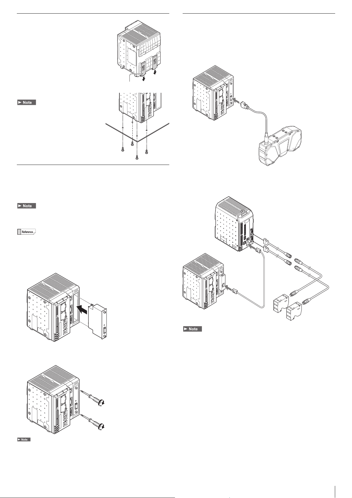
Installing the Controller
M4 screws
To Camera 1 connector
LJ-V Series Controller
(sold separately)
LJ-V Series Head
(sold separately)
Installing the Controller on a DIN Rail
The controller unit and the expansion unit
are designed to be mounted on a DIN rail.
Pull out the tab on the bottom in the
direction of the arrow to mount or
dismount the controller.
Connecting Camera Cables
Connect the camera to the camera connector of the controller.
If connecting only a single camera, attach it to the camera 1 connector.
When connecting a 3D camera XR-HT*** with the camera input unit
XG-EC80T (for 3D cameras) attached
Ta b
Installing the Controller at the Bottom
Mount the controller in a stable location that is
free from vibration.
Installing the Camera Input Unit
Mount the optional camera input unit (XG-EC80T: for 3D cameras,
CA-EC80LJ/XG-EC80LJ: for the LJ-V, CA-EC80HX/CA-EC80L/
XG-EC80L: for HX Series cameras [when using 16x speed], or CA-EC80/
XG-EC80: for area scan cameras) to the camera slot of the controller.
Make sure that there is no power to the controller before connecting the camera
input unit. Connecting the camera input unit while connected to a power source may
damage the unit or controller.
The figure below explains the installation procedure for the optional camera input
unit XG-EC80T (for 3D cameras). Use the same procedure to install other camera
input units.
1 Remove the protective cover from the camera slot, and install
the camera input unit.
To Camera 1 connector
Camera 1
When connecting LJ-V with the camera input unit CA-EC80LJ/
XG-EC80LJ (for LJ-V) attached
2 Tighten the upper and lower screws of the camera input unit to
fix the unit.
Tighten the screws to a torque of 1.5 [N·m].
• Bundle cables with a spiral tubing material. Direct bundling will concentrate the
cable load on the bindings, which can result in cable damage or short circuit.
• In the absence of other specifications, the minimum cable flexibility (R) should be 3
times the external diameter (5 times is recommended). Additionally, repeated
curvature and screw stress should be avoided. The minimum flexion is the same,
even when using flexible cable. Unless otherwise stated, use R100 or greater.
• Only CA-CH* camera cables can be used with high-speed cameras and 3D
cameras (XR-HT***).
• Use the Ethernet cable for LJ-V connection (OP-87736) or a commercial Ethernet
cable (category 7 or above, or 10GBASE-T-compatible one) when connecting LJ-V.
• If a different camera is connected, it may cause improper functioning, do not
connect to a different camera.
5
Page 6
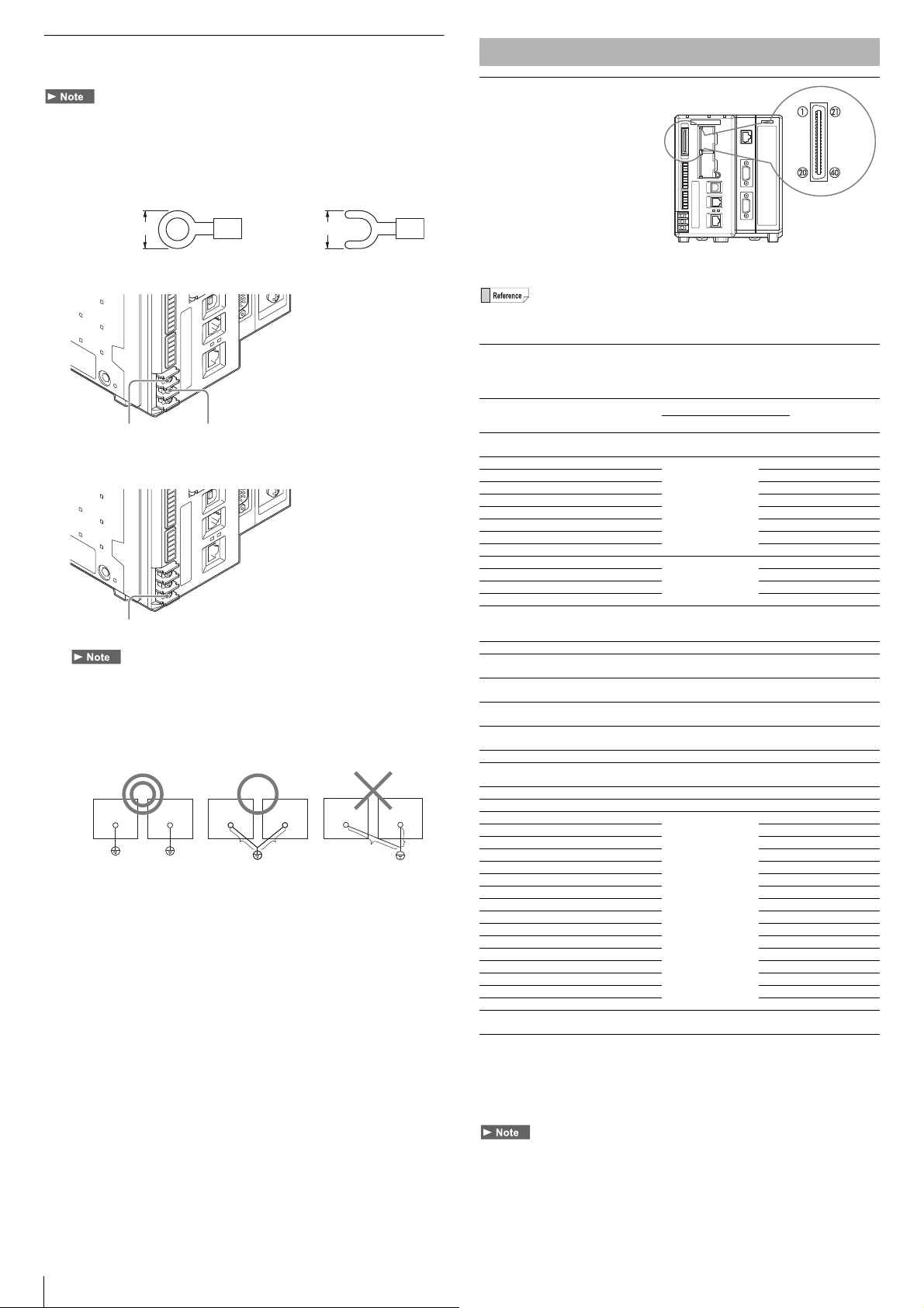
Connecting the 24 VDC Power Source
5.8 mm or less 5.8 mm or less
Ring terminal Y terminal
Connect the 24 VDC Connect the 0 VDC
Connect the ground wire
Peripheral
Device
Peripheral
Device
Peripheral
Device
A
B
A
B
D-type ground* (third ground)
(ground resistance 100 Ω)
A = B
D-type ground* (third ground)
(ground resistance 100 Ω)
A > B
A < B
Connect a 24 VDC power source to the power source/earth terminal.
• Use an AWG14 - AWG22 Power cable.
• Always connect the Frame Ground Terminal of the 24 VDC power source to
a D type ground.
• Use a Crimping Terminal the size shown below that matches an M3 screw.
• Securely tighten with a screw tightening torque of 0.5 - 0.75 [N·m].
1 Connect a 24 VDC and 0 V to the Power Terminal.
2 Connect the ground wire to the ground port.
• Ground each device separately.
• Use a D type ground.
• Keep ground resistance under 100 Ω.
• Keep the ground wire as short as possible.
• If it is not possible to ground each device separately, ground them together.
However, make sure that the electrical cables are the same as shown below.
Parallel I/O Interface
Connector Specifications
The following values show the
parallel I/O connector
specifications for the system.
Connector
FX2B-40SA-1.27R
(Hirose Electric)
Color Flat Cable
UL20028-FRX-CF-40 (Fujikura, equivalent wire gauge AWG28)
In normal situations, use the specialized parallel connection cable (3 m) OP-51657
(sold separately).
Parallel I/O Assignment: When Using Cable OP-51657
(Sold Separately)
Ter mi nal
No.
name
1 COMIN2
2IN0Input 0
3 IN1 Input 1 (for encoder) 1 A Orange
4 IN2 Input 2 (for encoder) 2 A Yellow
5 IN3 Input 3 (for encoder) 3 A Green
6 IN4 Input 4 4 B Blue
7 IN5 Input 5 5 B Purple
8IN6Input 6 6 BGray
9 IN7 Input 7 7 B White
10 IN8 Input 8
11 IN9 Input 9 1 B Brown
12 IN10 Input 10 2 B Red
13 IN11 Input 11 3 B Orange
14 IN12 Input 12
15 IN13 Input 13 Reset input 0 B Green
16 IN14 Input 14
17 COMOUT2
18 OUT0 Output 0
19 OUT1 Output 1
20 OUT2 Output 2 BUSY output 0 D Black
21 OUT3 Output 3
22 OUT4 Output 4 Trigger 1 ready output 0 D Red
23 OUT5 Output 5 Trigger 2 ready output 0 D Oran ge
24 OUT6 Output 6
25 OUT7 Output 7 1 D Green
26 OUT8 Output 8 2 D Blue
27 OUT9 Output 9 3 D Purple
28 OUT10 Output 10 4 D Gray
29 OUT11 Output 11 5 D White
30 OUT12 Output 12 6 D Black
31 OUT13 Output 13 7 D Brown
32 OUT14 Output 14 8 D Red
33 OUT15 Output 15 9 D Orange
34 OUT16 Output 16 10 D Yellow
35 OUT17 Output 17 11 D Green
36 OUT18 Output 18 12 D Blue
37 OUT19 Output 19 13 D Purple
38 OUT20 Output 20 14 D Gray
39 OUT21 Output 21 15 D White
40 COMOUT2
Reference
Common for Parallel
Inputs
Common for Parallel
Outputs (1 of 2)
Common for Parallel
Outputs (2 of 2)
Initial assignment status
Variable function
––BBrown
Custom command
parameter input
Custom command
No. input
Custom command
execution input
(terminal)
Output data switch
input
– – – Purple
Handshaking success
output
Handshaking failure
output
Custom command
ready output
System variables
%OutDataA data
output
–––Black
*1 Initial assignment status is a status that system variables are assigned to each
terminal by the initial environment settings value. This may be different from the
original description due to setting change.
*2 For more details on each variable function, see the "List of System Variables" of
XG VisionEditor reference manual.
*1
Circuit
*2
diagram
Bit
0BRed
0BBlack
0 B Yellow
0BBlue
0DGray
0DWhite
0DBrown
0 D Yellow
Color
6
• COMOUT2 for Pin 17 and Pin 40 are common.
• Power source 0 V and COMIN1, COMIN2 (Connector), COMIN2 (Terminal block),
COMOUT1, COMOUT2, COMOUT_F+, COMOUT_F-, COMOUT2_F+, and
COMOUT2_F- are all isolated.
• COMIN2 is a common terminal for input to the controller, via the parallel I/O terminals.
• COMOUT2 is a common terminal for output from the controller, via the parallel I/O
terminals.
Page 7
Terminal Block 1
INPUT
COMIN1
or
COMIN2
3.3kΩ
10kΩ
INPUT
6.2kΩ
4.7kΩ
COMIN1
or
COMIN2
10kΩ
1kΩ
40V
0.3A
COMOUT
OUTPUT
Poly Switch
10kΩ
22kΩ
33V
104
COMOUT_F+
COMOUT_F-
OUTPUT
0.3A
Poly Switch
10kΩ
1kΩ
33V
0.3A
OUTPUT
Poly Switch
COMOUT
Input/Output Circuit
Standard Specifications
The following values show the terminal block 1 specifications for the system.
Tightening with a force above the standard torque may cause damage to the terminal
block.
OUT1 connector
• Socket block:
MC1.5/9-ST-3.5BK
(Phoenix Contact)
• Compatible electric wires:
AWG16 to 28
• Terminal block screw torque:
0.25 N·m or less
IN1 connector
• Socket block:
MC1.5/6-ST-3.5BK
(Phoenix Contact)
• Compatible electric wires:
AWG16 to 28
• Terminal block screw torque:
0.25 N·m or less
Pin Settings
OUT1 connector
No.
1
2
3
4
5
6
7
8
9
Name
Terminal ID is noted in ( )
OUT22 (STO) Output 22
OUT23 (OR) Output 23
F_OUT2 (ERR) High speed output 2 Error 0 output 0 C
F_OUT3 (RUN) High speed output 3 Run mode output 0 C
COMOUT1
(COMOUT)
F_OUT0 (FLS1) High speed output 0 Strobe output 1 0 C
F_OUT1 (FLS2) High speed output 1 Strobe output 2 0 C
COMOUT1_F+
(COM1F+)
COMOUT1_F(COM1F-)
Reference
Common for terminal
block output (1, 2)
Common
for high speed output (+)
(3, 4 and 6, 7)
Common
for high speed output (-)
(3, 4 and 6, 7)
IN1 connector
No.
1
2
3
4
5
6
*1 Initial assignment status is a status that system variables are assigned to each
*2 For more details on each variable function, see the "List of System Variables" of
• Power source 0 V and COMIN1, COMIN2 (Connector), COMIN2 (Terminal block),
• COMOUT1 is the common terminal for output terminals 1 and 2.
• COMOUT_F+ and COMOUT_F- are the common terminal for output terminals 3, 4
• COMIN1 is the common terminal for input terminals 2 through to 6.
Name
Terminal ID is noted in ( )
COMIN1 (COMIN1)
IN15 (PLC) Input 15
F_IN0 (TRG1) High speed input 0 Trigger 1 input 0 A
F_IN1 (TRG2) High speed input 1 Trigger 2 input 0 A
F_IN2 (TEST) High speed input 2 Test run input 0 A
F_IN3 (EXT) High speed input 3 Disable trigger input 0 A
Reference
Common
for terminal block input
terminal by the initial environment settings value. This may be different from the
original description due to setting change.
XG VisionEditor reference manual.
COMOUT1, COMOUT2, COMOUT_F+, COMOUT_F-, COMOUT2_F+, and
COMOUT2_F- are all isolated.
and 6, 7.
Initial assignment status *
Variable function *
I/O terminal/
Parallel I/O output
change strobe
Outputs the total status
output
–––
–––
–––
Initial assignment status *
Variable function *
–––
Custom command
execution input (PLC)
1
2
Bit
0D
0D
1
2
Bit
0B
Circuit
diagram
Circuit
diagram
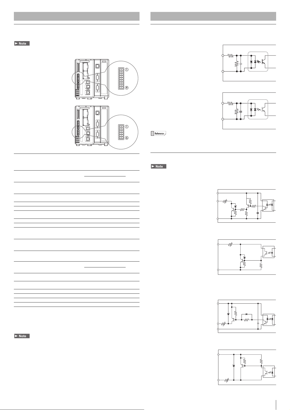
Input Circuit
Input circuit diagram
Circuit A
(compatible with F_IN0 to 7, EV)
• Max. superimposed voltage:
26.4 V
• ON voltage: 10.8 V or greater
• ON current: 3 mA or greater
• OFF voltage: 5 V or less
• OFF current: 1 mA or less
Circuit B (other inputs)
• Max. superimposed voltage:
26.4 V
• ON voltage: 10.8 V or greater
• ON current: 2 mA or greater
• OFF voltage: 3 V or less
• OFF current: 0.3 mA or less
For more details on the common to be connected, see the "Parallel I/O Interface"
(page 6), and "Terminal Block 1" (page 7).
Output Circuit
The working current of the Poly Switch for the over current is 1 A. Use the current of
1 A or more for the output.
Output circuit diagram (NPN output type)
Circuit C (F_OUT0 to 7)
• Max. superimposed voltage:
30 V
• Max. sink current:
50 mA
• Leakage current:
0.1 mA or less
• Residual voltage:
1.4 V or less (50 mA), 1.0 V or less (20 mA)
Circuit D (Other outputs)
• Max. superimposed voltage:
30 V
• Max. sink current:
50 mA
• Leakage current:
0.1 mA or less
• Residual voltage:
1.4 V or less (50 mA), 1.0 V or less (20 mA)
Output circuit diagram (PNP output type, when the model has P at
the end of the name)
Circuit C (F_OUT0 to 7)
• Max. superimposed voltage:
30 V
• Max. sink current:
50 mA
• Leakage current:
0.1 mA or less
• Residual voltage:
1.4 V or less (50 mA), 1.0 V or less (20 mA)
Circuit D (Other outputs)
• Max. superimposed voltage:
30 V
• Max. sink current:
50 mA
• Leakage current:
0.1 mA or less
• Residual voltage:
1.4 V or less (50 mA), 1.0 V or less (20 mA)
COMOUT_F+
OUTPUT
COMOUT_F-
0.3A
Poly Switch
10kΩ
22kΩ
22kΩ
22kΩ
22kΩ
104
40V
7
Page 8

Main Specifications
Model type XG-8700T
Pixels • With CA-HX500C/HX500M connected
Camera input • With CA-EC80L/XG-EC80L equipped: 1 color/monochrom e Area Scan Camera (Compatible with CA-HX500C/HX500M/HX200C/
Trigger input Simultaneous capture by up to 4 cameras/individual capture can be selected. (when CA-EC80/XG-E800 is not connected, images from up
Main image processor DSP (High-speed)
Registered number of inspection settings SD cards 1 and 2 can each hold 1000 programs (depending on the size of the SD card and the size of the programs), external switching
Number of registered screens Maximum 1000 screens for each program (depending on SD card size), Image compression, image registration of position adjustment
SD card • SD card slot x 2 (SDHC compatible)
Interface Controlled input (compatible with
arbitrary assignment)
Controlled output (compatible with
arbitrary assignment)
Encoder input For the Open Collector Output (Dedicated to 24 V outputs) using the Control Input Terminal (2 systems)
Monitor output Analog RGB Output, XGA (1024 x 768, 24 bit color)/SVGA (800 x 60, 24 bit color) Switch (can be set by the inspection settings unit)
Operation indicators LED display for Power ON, Operation and ERROR
RS-232C 2 Port up to Maximum baud rate of 230400 bps
PLC link • Numerical value output and control input/output using the RS-232C port or Ethernet port enabled (Do not use to connect to CC-Link,
Ethernet • Numerical value output, and control input/output enabled.
USB • By the connection of KEYENCE PC application software, in addition to numerical value output and control input/output, uploading and
CC-Link • By connecting the optional CC-Link expansion unit CA-NCL10E, numerical value input/output and control input/output are enabled.
EtherNet/IP Numerical value input/output, and control input/output by using the Ethernet port enabled.
PROFINET Numerical value input, and control input/output by using the Ethernet port enabled.
Console • By the optional OP-84231, OP-84236 (without silk screen printing), various menu can be used
Touch panel • Setting operation from the CA Series touch panel used by the RS-232 port is possible
5 mega-pixel mode: 2432(H) x 2040(V), approx. 4.96 mega-pixels
2 mega-pixel mode: 1600(H) x 1200(V), approx. 1.92 mega-pixels
• With CA-HX200C/HX200M connected
2 mega-pixel mode: 1600(H) x 1200(V), approx. 1.92 mega-pixels
• With CA-HX048C/HX048M connected
470 k pixel mode: 784(H) x 596(V), approx. 470,000 pixels
310 k pixel mode: 640(H) x 480(V), approx. 310,000 pixels
240 k pixel mode: 512(H) x 480(V), approx. 240,000 pixels
• With XG-H500C/H500M connected
5 mega-pixel mode: 2432(H) x 2050(V), approx. 4.99 mega-pixels
• With XG-200C/S200C/H200C/200M/S200M/H200M connected
2 mega-pixel mode: 1600(H) x 1200(V), approx. 1.92 mega-pixels
1 mega-pixel mode: 1024(H) x 960(V), approx. 980,000 pixels
• With XG-H100C/H100M connected 1000(H) x 1000(V), 1 mega-pixel
• With XG-035C/S035C/H035C/035M/S035M/H035M connected
310 k pixel mode: 640(H) x 480(V), approx. 310,000 pixels
240 k pixel mode: 512(H) x 480(V), approx. 240,000 pixels
• With XR-HT40M connected: 2048 (H) x 2048 (V), approx. 4.19 mega-pixels
• With XR-HT15M connected: 1408 (H) x 1408 (V), approx. 1.98 mega-pixels
• With LJ-V connected:
512 (H) x 16384 (L), approx. 8.39 mega-pixels
1024 (H) x 8192 (L), approx. 8.39 mega-pixels
2048 (H) x 4096 (L), approx. 8.39 mega-pixels
HX200M/HX048C/HX048M)
• With CA-EC80HX equipped: 1 color/monochrome Area Scan Camera (Compatible with CA-HX500C/HX500M/HX200C/HX200M/
HX048C/HX048)
• With XG-EC80T equipped: 1 3D ca mera (Compatible with XR-HT40M/H T15M)
• With CA-EC80LJ/XG-EC80LJ equipped: 1 LJ-V (Compatible with LJ-V7000/7000P)
• With CA-EC80/XG-EC80 equipped: 2 color/monochrome Area Scan Cameras (Compatible with CA-HX500C/HX500M/HX200C/
HX200M/HX048C/HX048M and XG-H500C/200C/S200C/H200C/H100C/035C/S035C/H035C/H500M/200M/S200M/H200M/H100M/
035M/S035M/H035M, mixed connection possible)
Based on the connection of the expansion unit CA-E800/XG-E800, wh en the XG-EC80T is equipped, 1 3D Camera expansion unit
(maximum 2 cameras) can be connected, when the CA-EC80LJ/XG-EC80LJ is equipped, 1 LJ-V expansion unit (maximum 2 LJ-V) can be
connected, when the CA-EC80HX/CA-EC80L/XG-EC80L is equipped, 1 extra area scan camera (only the CA-HX500C/HX500M/HX200C/
HX200M/HX048C/HX048M; 2 cameras maximum) can be connected and when the CA-EC80/XG-EC80 is equipped up to 2 Area Scan
Camera expansion units (maximum 4 cameras) can be connected (Mixed connection possible). Mixed connection of XG-EC80T and
CA-EC8LJ/XG-EC80LJ is not supported.
to two cameras can be captured at the same time)
possible.
images and partial image registration available. External switching possible based on variable reference.
• Compatible with OP-87133 (512MB), CA-SD1G (1GB: installed standard to SD1 slot), and CA-SD4G (4GB: SDHC)
• 20 input (including four high speed inputs designed for trigger input)
• Input rating 26.4 V or lower, 2 mA or greater (3 mA or greater for high speed input terminal)
• 28 output (including four high speed outputs designed for FLASH outputting linked to external device)
• NPN open collector *1 Maximum 50 mA (30 V or less)
The digit output or control input/output and CA Series Touch Panel interface can be switched.
EtherNet/IP and PROFINET.)
• Following PLCs are supported via link unit:
KEYENCE: KV-700 Series, KV-1000 Series, KV-3000 Series, KV-5000 Series, KV-5500 Series, KV Nano Series
Mitsubishi Electric: MELSEC A Series (RS-232C only), Q Series, L Series
OMRON: SYSMAC C Series (RS-232C only), CP1/CS1/CJ1/CJ2 Series
YASKAWA Electric: MP900 Series (RS-232C only), MP2000 Series
• By the connection of KEYENCE PC application software, in addition to the function described above, uploading and downloading the
inspection settings, simulations, data, including image data can be sent or received.
• VisionDatabase function support (sold separately)
• For the FTP client function, the VNC server function (for clients other than for PC it will be only for the screen display), and BOOTP
function.
• 1000BASE-T/100BASE-TX/10BASE-T
downloading the inspection settings, simulations, data, including image data can be sent or received
• VisionDatabase function support (sold separately)
•USB2.0
(Do not use to connect to PLC Link, EtherNet/IP and PROFINET.)
• Compatible to the Ver.1.10 remote device station, Ver.2.00 remote device station
(Do not use to connect to PLC Link, CC-Link and PROFINET.)
• Compatible to the cyclic communication (max.1436 byte), and message communication
• Maximum number of connections 32
• Compatible with the conformance test Version.CT10.
• Compatible to the cyclic communication (max. 1408 byte)
• Compatible to the aperiodic (recorded data) communication
• Compatible with the Conformance Class A
• Do not use to connect to PLC Link, CC-Link and EtherNet/IP.
• Compatible to the operation assignment settings to the console button
• Compatible to the button activation and deactivation of each user group
• For the dedicated touch menu or the operation button
*2
8
Page 9

Model type XG-8700T
Display language Japanese/English/Simplified Chinese/Traditional Chinese/German selectable
Illumination control Based on connecting the Illumination Expansion Unit
Rating Power source voltage 24 V DC ± 10%
Consumption current • Using area cameras: 3.6 A (2 cameras connected)/4.6 A (4 cameras connected).
Environmental resistance Ambient temperature 0 to + 45 ˚C
Ambient operating humidity 35 to 85% RH (no condensation)
Weight Approx. 1,600 g
(Choose the default language to be used when turning power ON)
The optional lighting and light intensity control CA-DC30E/DC21E of the LED illumination (12V, 24V) is possible, 2ch per unit, and a
maximum number of connected units of 4.
• Using 3D cameras: 3.5 A (1 camera connected)/4.8 A (2 cameras connected).
• Using LJ-V: 2.6 A (1 unit connected)/2.8 A (2 units connected).
• For all types, the maximum consumption includes inrush current during start up.
*1 For the type where a P is added to the end of the main unit, it will become a PNP Open Collector.
*2 Models equipped with the Ethernet port in the CPU unit support Ethernet port direct connection.
9
Page 10

Dimensions
M4
Depth:6.0
M4
Depth:6.0
M4
Depth:11.0
M4
Depth:11.0
DIN-rail
mounts
134.6
23.5
132.0
35.9
83.3
65.3
116.7(92.0)
153.0
6.0
112.0
16.5
80.0
153.0
150.5
379.8
347.0
301.9
256.8
211.7
166.6
134.6
6.0
Controller Unit
XG-8700T + XG-EC80T
Controller Unit
XG-8700T + CA-EC80LJ/XG-EC80LJ
134.6
153.0
6.0
23.5
132.0
116. 7(85.0)
M4
Depth:11.0
DIN-rail
mounts
35.9
83.3
66.3
M4
Depth:11.0
112.0
M4
Depth:6.0
80.0
16.5
M4
Depth:6.0
With camera expansion unit (CA-E800/XG-E800), CCLink unit
(CA-NCL10E), and illumination expansion unit
(CA-DC21E) connected
10
Page 11

11
Page 12

WARRANTIES AND DISCLAIMERS
Copyright (c) 2014 KEYENCE CORPORATION. All rights reserved.
13088E 1074-1 96M13089 Printed in Japan
(1) KEYENCE warrants the Products to be free of defects in materials
and workmanship for a period of one (1) year from the date of
shipment. If any models or samples were shown to Buyer, such
models or samples were used merely to illustrate the general type and
quality of the Products and not to represent that the Products would
necessarily conform to said models or samples. Any Products found
to be defective must be shipped to KEYENCE with all shipping costs
paid by Buyer or offered to KEYENCE for inspection and examination.
Upon examination by KEYENCE, KEYENCE, at its sole option, will
refund the purchase price of, or repair or replace at no charge any
Products found to be defective. This warranty does not apply to any
defects resulting from any action of Buyer, including but not limited to
improper installation, improper interfacing, improper repair,
unauthorized modification, misapplication and mishandling, such as
exposure to excessive current, heat, coldness, moisture, vibration or
outdoors air. Components which wear are not warranted.
(2) KEYENCE is pleased to offer suggestions on the use of its various
Products. They are only suggestions, and it is Buyer's responsibility to
ascertain the fitness of the Products for Buyer’s intended use.
KEYENCE will not be responsible for any damages that may result
from the use of the Products.
(3) The Products and any samples ("Products/Samples") supplied to
Buyer are not to be used internally in humans, for human
transportation, as safety devices or fail-safe systems, unless their
written specifications state otherwise. Should any Products/Samples
be used in such a manner or misused in any way, KEYENCE
assumes no responsibility, and additionally Buyer will indemnify
KEYENCE and hold KEYENCE harmless from any liability or damage
whatsoever arising out of any misuse of the Products/Samples.
(4) OTHER THAN AS STATED HEREIN, THE PRODUCTS/SAMPLES
ARE PROVIDED WITH NO OTHER WARRANTIES WHATSOEVER.
ALL EXPRESS, IMPLIED, AND STATUTORY WARRANTIES,
INCLUDING, WITHOUT LIMITATION, THE WARRANTIES OF
MERCHANTABILITY, FITNESS FOR A PARTICULAR PURPOSE,
AND NON-INFRINGEMENT OF PROPRIETARY RIGHTS, ARE
EXPRESSLY DISCLAIMED. IN NO EVENT SHALL KEYENCE AND
ITS AFFILIATED ENTITIES BE LIABLE TO ANY PERSON OR
ENTITY FOR ANY DIRECT, INDIRECT, INCIDENTAL, PUNITIVE,
SPECIAL OR CONSEQUENTIAL DAMAGES (INCLUDING,
WITHOUT LIMITATION, ANY DAMAGES RESULTING FROM LOSS
OF USE, BUSINESS INTERRUPTION, LOSS OF INFORMATION,
LOSS OR INACCURACY OF DATA, LOSS OF PROFITS, LOSS OF
SAVINGS, THE COST OF PROCUREMENT OF SUBSTITUTED
GOODS, SERVICES OR TECHNOLOGIES, OR FOR ANY MATTER
ARISING OUT OF OR IN CONNECTION WITH THE USE OR
INABILITY TO USE THE PRODUCTS, EVEN IF KEYENCE OR ONE
OF ITS AFFILIATED ENTITIES WAS ADVISED OF A POSSIBLE
THIRD PARTY’S CLAIM FOR DAMAGES OR ANY OTHER CLAIM
AGAINST BUYER.
warranty disclaimers or damage limitations may not apply.
In some jurisdictions, some of the foregoing
BUYER'S TRANSFER OBLIGATIONS:
If the Products/Samples purchased by Buyer are to be resold or
delivered to a third party, Buyer must provide such third party with a
copy of this document, all specifications, manuals, catalogs, leaflets
and written information provided to Buyer pertaining to the Products/
Samples.
12
E 1101-3
 Loading...