

Page 1

96M11880
3D Laser Scanning Microscope
VK-X100K/X105/X110
VK-X200K/X210
User’s Manual
Read this manual before using the system in order to achieve maximum
performance.
Always keep this manual in a safe place for future reference.
Getting Started
1
Set-Up
2
Before Measuring
3
Mounting Optional Devices
4
5
Appendix
Maintenance
Dimensions/Specifications
Page 2

Introduction
CAUTION
This manual describes the handling, operating procedures and precautions for the “3D Laser Scanning
Microscope VK-X100K/X200K Series.”
Read this manual thoroughly before using the system to get the maximum performance out of the “3D
Laser Scanning Microscope VK-X100K/X200K Series.”
Keep this manual at hand for reference whenever needed.
Symbols
This manual uses the following symbols to show important information at a glance.
Be sure to read this section.
DANGER
WARNING
NOTICE
Important
Reference
It indicates a hazardous situation which, if not avoided, will result in death
or serious injury.
It indicates a hazardous situation which, if not avoided, could result in
death or serious injury.
It indicates a hazardous situation which, if not avoided, could result in
minor or moderate injury.
It indicates a situation which, if not avoided, could result in product
damage as well as property damage.
It indicates cautions and limitations that must be followed during
operation.
Point
It indicates additional information on proper operation.
It indicates tips for better understanding or useful information.
It indicates reference pages in this manual or other manual.
Precautions
• Reprinting any part or all of this manual without permission is prohibited.
• Please note that the content of this manual is subject to change without notice for the purpose of
improvement.
• Should you find any problem with the content of this manual, such as an unclear point, mistake, or erro-
neous omission, contact your nearest KEYENCE office.
• If there are missing or misplaced pages, we will provide a new copy of this manual.
The company names and product names used in this manual are registered trademarks or trademarks of
their respective companies.
Page 3

Safety Information for VK-X100K/VK-X200K Series
WARNING
CAUTION
NOTICE
To prevent damage and to correctly use the “3D Laser Scanning Microscope VK-X100K/X200K Series”
(VK-X100K/X200K Series), follow the precautions below.
Precautions for use
• Do not use this product for the purpose to protect a human body or a part of human body.
• This product is not intended for use as explosion-proof product. Do not use this product
in a hazardous location and/or potentially explosive atmosphere.
• Confirm that the components of our product are working normally before use.
• Considering the possibility of our product failing, use the product after implementing
sufficient safety measures to prevent any damage.
• Do not allow any foreign material to enter inside. It may result in fire, electric shock,
malfunction or accident.
• Never remove the case cover of the VK-X100K/X200K Series. Touching the inside may
result in an electric shock.
• Do not touch the lens revolver while it is moving, doing so risks catching hands or fingers
in the mechanism.
• The VK-X100K/X200K Series is grounded to the case. Make sure that the device is properly
insulated if installed in a high-noise environment or a positive ground situation. Failure to
do so may cause damage or electric shock.
• Please note we cannot guarantee the function and performance of products that are
modified or used outside of the ratings shown in the specifications.
• When our product is used in conjunction with equipment from other companies, the
normal function and sufficient performance may not be attained depending on the
condition of use and the environment. Be sure to make sufficient assessment before such
use.
• As the VK-X100K/X200K series uses precision optics, avoid any vibration or impact. Doing
so may cause damage.
• Make sure that the power of the VK-X100K/X200K Series is turned off before removing/
inserting the power cable, controller cable, or camera cable. Doing so may cause failure.
• Make sure that the lens does not come in contact with the sample. Doing so may cause
damage.
• Do not place objects that weigh more than 5 kg on the X-Y stage. Doing so may cause
damage.
not
• Do
• Do not remove/insert the USB cable while the ACCESS lamp on the control unit is lit. Doing
turn the power off during measurement. Otherwise, some or all of the settings may
be lost.
so may cause damage.
96M11880
1
Page 4

Safety Information for VK-X100K/VK-X200K Series
Important
CAUTION
NOTICE
CAUTION
NOTICE
Important
• Make sure that the ambient temperature is stable during measurements.
• Wait one hour or more for preheating after turning on the power before taking
measurements.
• When the lens section is dirty, clean it with the lens blower or with a cotton swab
dipped in alcohol.
• Make sure that the device is not subject to vibration during measurement. It is
recommended that an anti-vibration stand be used.
• The measurement unit, the controller cable A/B, and the camera cable are adjusted
together as a set. Make sure that all of them bear the same serial number.
Precautions for abnormalities
Turn off the power immediately in the following cases. Using the unit in abnormal conditions
could cause fire, electric shock, or accident. Contact your nearest KEYENCE office for repair.
• If water or foreign material enters inside the VK-X100K/X200K Series.
• If the unit is dropped or the case is damaged.
• If the unit emits smoke or odor.
Back up all data saved on the control PC before sending it in for repairs. The repair procedure
carries a risk of data loss.
Additionally, regular periodic backups are recommended.
Precautions for installation
Install the VK-X100K/X200K series so that it is level. There is a risk of the falling unit causing
injuries.
• Do not obstruct the ventilation hole or the ventilation fan of the control unit. Internal
temperature increases may result in damage.
Avoid installation in the following locations. Doing so may cause failure.
• Locations where the device will be subject to direct vibrations
• Locations where the ambient temperature drops below 15°C or exceeds 28°C
• Locations where the ambient humidity drops below 35% RH or exceeds 65% RH (no
condensation)
• Locations where the temperature changes rapidly
• Locations where the device will be exposed to a direct breeze from an air conditioner
• Locations where there are corrosive gases or volatile inflammable materials
• Locations with large amounts of airborne dust, salt, iron or greasy fumes
• Locations with a risk of exposure to airborne water, oil or chemical droplets
• Locations where a strong magnetic or electric field is generated
• Locations where the voltage varies greatly
• It is recommended that the device be installed on a commercially available anti-
vibration stand.
2
VK-X100K/X200K User’s Manual
Page 5

Precautions for the power supply
WARNING
CAUTION
The VK-X100K/VK-X200K Series is Class I equipment. When installing this device, connect
the protective grounding terminal of the power supply cord set to the protective grounding
conductor of the installation place.
Otherwise, it may cause electric shock or product damage.
• Do not bend forcefully or put any heavy objects on the power cable. Doing so may lead to
a cable break, resulting in fire or electric shock. Do not use a damaged cable.
• Make sure to use the VK-X100K/X200K Series under proper power supply voltage;
otherwise, an electric shock, fire or product malfunctions may occur.
• The power supply cord set is not provided with the VK-X100K/X200K Series. Use a power
cable that complies with the regulations and standards in the country or the region in
which the VK-X100K/X200K Series are used.
Safety Information for VK-X100K/VK-X200K Series
VK-X100K/X200K User’s Manual
3
Page 6

Safety Information for VK-X100K/VK-X200K Series
CAUTION
Fixing metal fittings
Precautions for transportation
• When transporting the device, carry it by holding the indentation in the measurement unit
or the handle of the pedestal. Carrying the device by the measurement portion may
damage it. There is also a chance of injury or damage if the device falls.
• Carry the measurement portion of the device by the recessed portions on the front and
back of the unit.
• Be sure to fix the X-Y stage with a fixture before transportation. Be sure to also lock the Z
stage using the focusing handle.
4
VK-X100K/X200K User’s Manual
Page 7

• As the VK-X100K/X200K series uses precision optics, avoid any vibration or impact. Doing
NOTICE
Important
NOTICE
NOTICE
so may cause damage.
• Be sure to remove the objective lenses from the revolver when transporting. Doing so may
cause damage.
• Be sure to use packaging materials specified by KEYENCE for transportation. Doing so
may cause damage.
• The VK-X100K/X200K Series is a super precision optical instrument. Sudden changes in
temperature may result in damage, including condensation and misalignment of the
optical axis. Leave the device at room temperature (between 15°C and 28°C) for 24 hours
after unpacking.
• The removed fixing metal fittings and the lens cases are required when the VK-X100K/
X200K Series are transported. Be sure to keep them in a secure location.
Precautions for storage
Safety Information for VK-X100K/VK-X200K Series
• Store the device in its packaging if it will not be used for a long period of time. Doing so
may cause failure.
Avoid storing in the following locations. Doing so may cause failure.
• Locations where the device will be subject to direct vibrations
• Locations where the ambient temperature drops below 0°C or exceeds +40°C
• Locations where the ambient humidity drops below 35% RH or exceeds 65% RH (no
condensation)
• Locations where the temperature changes rapidly
• Locations where there are corrosive gases or volatile inflammable materials
• Locations with large amounts of airborne dust, salt, iron or greasy fumes
• Locations with a risk of exposure to airborne water, oil or chemical droplets
• Locations where a strong magnetic or electric field is generated
• Locations where the device may be exposed to direct sunlight, wind, or rain
• Locations that are unstable or where the device may fall
Other precautions
When VK-X100K/X105/X110/X200K/X210 gets dirty, clean with a dry cloth.
VK-X100K/X200K User’s Manual
5
Page 8

Safety Precautions on Laser Products
WARNING
WARNING
Use of controls, adjustments or procedures other than those specified herein may result in
hazardous laser radiation exposure.
The VK-X100K/X200K Series employ a semiconductor laser as the light source.
Model VK-X100K/X105/X110 VK-X200K/X210
Wavelength 658 nm (Red laser) 408 nm (Violet laser)
Output 0.95 mW 0.95 mW
Pulse width 1 ns —
Follow the instructions mentioned in this manual. Otherwise, injury to the human body (eyes
and skin) may result.
Precautions on Class 2 Laser Products
• Do not disassemble this product. Laser emission from this product is not automatically
stopped when it is disassembled.
• Do not stare into the direct or specularly reflected beam.
• Do not direct the beam at people or into areas where people might be present.
• Be careful of the path of the laser beam. If there is a possibility that the operator may be
exposed to the specular or diffuse reflections, block the beam by installing a protective
enclosure.
• Install this product so that the path of the laser beam is not as the same height as that of
human eye.
A Warning label is attached to the microscope unit as shown below.
VK-X105/X110
6
VK-X100K/X200K User’s Manual
Page 9

VK-X210
Laser Aperture
Warning label
Label Location
Safety Precautions on Laser Products
VK-X100K/X200K User’s Manual
7
Page 10

Precautions on Regulations and Standards
Wind so that 3 cables are going through
the clamp.
Install so that 1 cable is going through
the clamp.
CE Marking
Keyence Corporation has confirmed that this product complies with the essential requirements of the
applicable EC Directives, based on the following specifications. Be sure to consider the following specifi-
cations when using this product in a Member State of the European Union.
EMC directive (2004/108/EC)
• Applicable Standard EMI: EN61326-1, Class A
EMS: EN61326-1
1 Install the sleeve ferrite clamp ZCAT3035-1330 (TDK) at both ends of the USB cable.
2 Install the sleeve ferrite clamp ZCAT2035-0930A-BK(TDK) at the end of the camera cable (at the
side of the measurement unit).
8
VK-X100K/X200K User’s Manual
Page 11

Precautions on Regulations and Standards
Remarks:
These specifications do not give any guarantee that the end-product with this product incorporated com-
plies with this essential requirements of EMC Directive. The manufacturer of the end-product is solely
responsible for the compliance on the end-product itself according to EMC Directive.
Low-Voltage directive (2006/95/EC)
• Applicable Standard EN61010-1
EN60825-1 Class 2 laser product
• Overvoltage Category II
• Use this product under pollution degree 2.
• Install this product at an altitude of 2000 m or less.
• Indoor use only.
• This product is designed as a Class I equipment. Be sure to connect the protective earthing terminal on
the AC power cable to the protective earthing conductor in the building installation.
• The AC power inlet falls under a disconnecting device. Install this product to be able to remove the AC
cord set from the AC power inlet in abnormal situations immediately.
CSA Certification
This product complies with the following CSA and UL standards and has been certified by CSA.
• Applicable standard: CAN/CSA C22.2 No. 61010-1
UL61010-1
Be sure to consider the following specifications when using this product as a product certified by CSA.
• Overvoltage category II
• Use this product under pollution degree 2.
• Install this product at an altitude of 2000 m or less.
• Indoor use only.
• This product is designed as a Class I equipment. Be sure to connect the protective earthing terminal on
the AC power cable to the protective earthing conductor in the building installation.
• The AC power inlet falls under a disconnecting device.
Install this product to be able to remove the AC cord set from the AC power inlet in abnormal situations
immediately.
VK-X100K/X200K User’s Manual
9
Page 12

Precautions on Regulations and Standards
MEMO
10
VK-X100K/X200K User’s Manual
Page 13

Organization of This Manual
1
2
3
4
5
A
Chapter
1
Getting Started
Chapter
2
Set-Up
Chapter
3
Before Measuring
Chapter
4
Mounting Optional Devices
Chapter
5
Maintenance
Appendix
Dimensions/Specifications
This chapter describes the principles of the VK-X100K/X200K, the contents of the
packaging and the names of each part.
This chapter describes how to assemble the microscope unit and how to connect
each device.
This chapter describes the preparation and basic adjustments to be made before
taking measurements.
This chapter describes the optional devices and how to install them.
This chapter describes the procedure for replacing the lamp and the fuse in the
control unit.
This chapter describes the specifications and dimensions of the device.
VK-X100K/X200K User’s Manual
11
Page 14

Table of Contents
Safety Information for VK-X100K/VK-X200K Series .............................................................. 1
Safety Precautions on Laser Products ................................................................................. 6
Label Location .................................................................................................................7
Precautions on Regulations and Standards ......................................................................... 8
CE Marking ...................................................................................................................... 8
CSA Certification ............................................................................................................. 9
Organization of This Manual ............................................................................................... 11
Table of Contents ............................................................................................................... 12
Chapter 1 Getting Started
Summary of the VK-X100K/X200K Series ......................................................................... 1-2
Principles of the VK-X100K/X200K Series .................................................................... 1-2
System Configuration ................................................................................................... 1-5
Operating Environment ................................................................................................ 1-6
Unpacking ......................................................................................................................... 1-8
Unpacking the Control Unit and Control PC ................................................................ 1-8
Unpacking the Microscope Unit .................................................................................. 1-8
Checking the Package Contents ....................................................................................... 1-9
Checking the Installation Environment ............................................................................ 1-11
Part Names and Functions .............................................................................................. 1-12
Microscope Unit (Left/Front View) .............................................................................. 1-12
Microscope Unit (Right/Front View) ........................................................................... 1-13
Control Unit (Front View) ............................................................................................ 1-14
Control Unit (Rear View) ............................................................................................. 1-14
Chapter 2 Set-Up
Assembling the Microscope Unit ...................................................................................... 2-2
Unlocking the X-Y Stage Lock ..................................................................................... 2-2
Mounting the Rotating Stage ........................................................................................ 2-2
Mounting Optional Devices .......................................................................................... 2-2
Mounting the Objective Lenses ................................................................................... 2-3
Connections ...................................................................................................................... 2-4
Connection Diagram .................................................................................................... 2-4
Connection Procedure ................................................................................................. 2-6
12
VK-X100K/X200K User’s Manual
Page 15

Table of Contents
Chapter 3 Before Measuring
Sequence of Preparation before Measuring ..................................................................... 3-2
Startup and Shutdown ....................................................................................................... 3-3
Starting Up the System ................................................................................................ 3-3
Shutting Down the System ........................................................................................... 3-4
Measurement Basics (For Proper Measurement) ............................................................. 3-5
A Variety of the Standard Objective Lens and How to Select One .............................. 3-5
Correction in the Film Thickness Measurement ........................................................... 3-6
Adjusting the Positions of the Laser and the Camera .................................................. 3-7
Adjusting the Measurement Unit ....................................................................................... 3-8
Initializing Lens Position ............................................................................................... 3-8
Adjustment of the Observation Position/Magnification ................................................ 3-9
Adjusting Focus/Brightness ....................................................................................... 3-10
Chapter 4 Mounting Optional Devices
List of Optional Devices .................................................................................................... 4-2
Removing/Mounting the Measurement Unit ...................................................................... 4-4
Removing the Measurement Unit ................................................................................. 4-4
Conditions for Mounting the Measurement Unit ........................................................... 4-5
Mounting the Measurement Unit .................................................................................. 4-6
Mounting the Spacer for the VK-X210 ............................................................................... 4-7
Package List ................................................................................................................. 4-7
How to Use the Spacer ................................................................................................ 4-7
Mounting Spacers ...................................................................................................... 4-10
Mounting the Spacer for the VK-X105/X110 .................................................................... 4-12
Package List ............................................................................................................... 4-12
How to Use the Spacer .............................................................................................. 4-12
Mounting Spacers ...................................................................................................... 4-15
Mounting a 300 mm Wafer X-Y Stage ............................................................................. 4-17
Package List ............................................................................................................... 4-17
Mounting a 300 mm Wafer X-Y Stage ........................................................................ 4-17
Names and Functions of the Components of the 300 mm Wafer X-Y Stage ............. 4-19
Mounting the Stand for VK .............................................................................................. 4-20
Package List ............................................................................................................... 4-20
Mounting the Stand for VK ......................................................................................... 4-21
How to Use the Stand for VK ...................................................................................... 4-22
VK-X100K/X200K User’s Manual
13
Page 16

Table of Contents
Chapter 5 Maintenance
Replacing the Lamp in the Control Unit ............................................................................ 5-2
Replacing the Fuse ........................................................................................................... 5-4
Appendix
Specifications ....................................................................................................................A-2
Dimensions ........................................................................................................................A-4
VK-X105/X110 .............................................................................................................. A-4
VK-X210 ....................................................................................................................... A-4
VK-X100K/X200K (Control Unit) ...................................................................................A-5
Index ..................................................................................................................................A-6
14
VK-X100K/X200K User’s Manual
Page 17

1
Chapter
1
Getting Started
This chapter describes the principles of the VK-
X100K/X200K, the contents of the packaging and
the names of each part.
Getting Started
Summary of the VK-X100K/X200K Series ............ Page 1-2
Unpacking ............................................................. Page 1-8
Checking the Package Contents ........................... Page 1-9
Checking the Installation Environment .................Page 1-11
Part Names and Functions .................................. Page 1-12
VK-X100K/X200K User’s Manual
1-1
Page 18

1
Summary of the VK-X100K/X200K Series
Conventional optics
Laser
Half
Mirror
Photoreceptor
Sample
Confocal laser optics
Laser
Half
Mirror
Photoreceptor
Sample
Pinhole
Laser
Half
Mirror
Photoreceptor
Sample
Laser
Half
Mirror
Photoreceptor
Sample
Pinhole
Conventional optics
Confocal laser optics
This manual gives a summary of the VK-X100K/X200K
Series, which offers both magnified observation and height
measurements.
Getting Started
Principles of the VK-X100K/X200K Series
Confocal laser optics
The VK-X100K/X200K Series is equipped with laser confo-
cal technology that obtains images with a large depth of
field that are in focus across the entire screen and that
detect the finest details in the sample shape data.
In the laser confocal optics, a pinhole in front of the position
where the reflected light from the sample forms an image
(photoreceptor) ensures that no light other than that which
passes through the focal point of the objective lens reaches
the photoreceptor. Use of this type of optics as a sensor
allows for the maximum possible amount of light to reach
the photoreceptor and allows changes in the focal point to
be measured and used as height information. Additionally,
use of this technology in a microscope creates a device
with almost no flare and significantly better contrast than a
standard optical microscope.
The VK-X100K/X200K Series combines this laser confocal
optics with a high-speed X-Y scanner to create a high res-
olution focal image and gather height information (shape
and roughness) from the sample.
When out of focus
While conventional optics allow all of the reflected light into
the photoreceptor, confocal laser optics allow only a frac-
tion.
When in focus
Both conventional optics and confocal laser optics allow all
of the reflected light to enter the photoreceptor.
1-2
VK-X100K/X200K User’s Manual
Page 19

1
Principles of operation of the VK-X100K/X200K Series
Laser light source
Focusing lens
Pinhole
Photoreceptor
Polarizing
beam splitter
Objective lens
Sample
Half
mirror
Color CCD camera
X-Y Scan
Optics
White light source
Summary of the VK-X100K/X200K Series
Getting Started
The VK-X100K/X200K Series uses a two-way light source
comprised of a laser light source and a white light source.
The two light sources together provide the colors, laser
intensity and height information necessary to create deep
field color images, laser intensity images or height images.
Detection of intensity and height with laser
light
The light emitted from the laser light source of the laser
microscope is focused onto the surface of the sample via X-
Y scan optics and objective lens. The focused spot light
scans the image area within the field of view using the X-Y
scan optics. By dividing the field of view into 1024×768 pix-
els*1 to scan the image, the reflected light at each pixel is
detected by the photoreceptor.
By driving the objective lens in the Z axis to repeat the scan
of the image, the intensity of each pixel at every position on
the Z axis is obtained. With the Z axis position of the highest
intensity being the focal point, the height information and
the laser intensity are detected. This allows for in focus
laser intensity and height images to be obtained.
*1 When the measurement quality is “Fine”, 2048×1536 pixels
are used, and when “Super fine”, 3072×2403 pixels are used.
Height
information
Z axis position
[Z position]
Color
information
Received light intensity
[Intensity]
The device reads the intensity of each Z position for each of
the pixels on the 1024×768 pixel screen and determines
the Z axis position (= focal point) of the maximum intensity,
and records the intensity and color information for that posi-
tion. Based on this information, three types of image data
are constructed, a deep field color image, a laser intensity
image and a height image.
Creating a color image with a CCD camera
On the other hand, the light reflected from the white light
source is detected by the CCD camera. Color observation
in the natural colors as seen by the naked eye is achieved
by obtaining the color information for each pixel at the focal
point detected by the laser.
Focal point
Intensity
information
VK-X100K/X200K User’s Manual
Introduction to the digital microscope
functions
The VK-X100K/X200K Series have the same optics design
as a metal microscope with lens barrel, coaxial incident
light illumination optics and CCD camera built-in in the
measurement unit.
1-3
Page 20

Summary of the VK-X100K/X200K Series
1
1024 x 768 pixels
Laser light
1
2
3
4
Scan with the
laser in the
XY direction
Move the
objective lens
along the Z
axis and scan
with the laser
again
Repeat as
many times
as the Z
measurement
distance
End of
measurement
Z measurement
distance
The CCD image sensor is equipped with a pixel shift
method CCD camera with a maximum of 21.6 million
recording pixels, allowing for the capture of clear and high
resolution magnified observation images. Combined with
Getting Started
the digital zoom function, this offers high magnification
observation of up to 18000x*2.
*2 The VK-X200K Series allows observation at up to 24000x
magnification.
Data acquisition flow
Optics (area image sensing)
Electric signal processing
7. Each time the lens moves, the laser intensity, the RGB
data from the CCD camera and the linear scale value
at the time of storing the data are recorded in the focal
point memory (1024 × 768 pixels) of the control unit
(VK-X100K/X200K Series).
8. During the data acquisition, the laser intensity at each
pixel is monitored. This means that laser intensities
higher than those stored in the memory of the control
unit (VK-X100K/X200K Series) (i.e. light that is not
attenuated when it reaches the photoreceptor after
passing through the pinhole) will replace the previous
CCD camera RGB data, laser intensity and linear scale
values.
* When RPD mode is active, the peak value (focal point
position) of the laser intensity is calculated based on changes
in the laser intensity values gathered according to the pitch
set by the numerical aperture of the objective lens and the
result is stored in memory.
Output data creation
1. Laser light from a semiconductor laser scans first by a
resonant (horizontal) scanner in the horizontal direc-
tion.
2. The light then scans by a galvano (vertical) scanner in
the vertical direction producing an area scanning
beam.
3. The laser light that reflects off of the sample passes
through a polarized beam splitter in front of the laser
light source and then reaches the focusing lens, the
pinhole and the photoreceptor (photomultiplier).
4. Light that has passed through the focusing lens and is
focused at the pinhole only passes through the pinhole
reaching the photoreceptor (laser light that is out of
focus does not reach the photoreceptor).
5. The electrical signal sent by the photoreceptor upon
receiving the laser light is transformed into an image
(area information) based on sampling coupled with the
vertical and horizontal movements of the scanner.
6. Once image area scanning has completed, the lens
moves one step in the Z direction, where one step is
equal to the pitch, and repeats the scan.
1-4
VK-X100K/X200K User’s Manual
9. By repeating the optics and electrical signal process-
ing operations (steps 1 through 8), at the end of gath-
ering data, each pixel contains the RGB values to be
stored from the CCD camera, the laser intensity, and
the linear scale value of the location where the laser
intensity is highest.
By combining the data, a color image that is completely
in focus, a black and white image based on the laser
intensity, and a height (contrast) image based on the
linear scale value can be created.
Page 21

1
System Configuration
Stand (OP-82693)
Measurement unit (VK-X105/X110/X210)
Spacer (OP-38162/51246)
Large sample stage
Control unit (VK-X100K/X200K)
Display
Control
PC
Anti-vibration stand
300 mm wafer X-Y stage
(OP-51498)
Electric X-Y stage
(VK-S100K/S105/S110)
Observation Application
(VK-H1XVE)
Analysis Application
(VK-H1XAE)
Basic system Option
Particle Analysis Module
(VK-H1XG)
Image Assembling Application
(VK-H1XJ)
Measurement Analysis Module
(VK-H1XP)
ISO-25178 Surface Texture
Measurement Module (VK-H1XR)
The VK-X100K/X200K Series offers basic system along with optional devices and applications.
Summary of the VK-X100K/X200K Series
Getting Started
VK-X100K/X200K User’s Manual
1-5
Page 22

Summary of the VK-X100K/X200K Series
1
Important
•Measurement unit (VK-X105/X110/X210)
Measurement unit with semiconductor laser, color CCD
camera and scan optics built-in. This is used as a micro-
scope mounted on the pedestal provided.
Getting Started
• Control unit (VK-X100K/X200K)
The laser, CCD camera controller, scanner control board,
100 W halogen lamp that serves as the light source, and
so on are all built-in the control unit.
•Observation Application (VK-H1XVE)
This software controls the VK-X100K/X200K Series to cre-
ate laser intensity and height images. It adjusts the cam-
era shutter, the gain on the photoreceptor and the
scanning format.
The Observation Application is not
functional unless a control unit (VK-X100K/
X200K) is connected.
• Analysis Application (VK-H1XAE)
This software obtains data for color observation with high
contrast, image processing for 3D displays, and opera-
tion/analysis processing of shape measurement and sur-
face roughness from the laser intensity data and height
data obtained by the Observation Application.
Operating Environment
To activate the VK-X100K/X200K Series, an environment
that meets the following conditions is required.
Control PC main specifications
Item Specifications
Control
PC
OS Windows 7 Professional 32-bit
CPU Intel Core™2 Duo E6300 or higher
Memory 2048 MB or more
USB port USB 2.0
HDD 160 GB or more
Video card KEYENCE-specified product (NVIDIA
The control PC that can be used with the VK-
X100K/X200K Series is KEYENCE-specified one.
Windows 7 Professional 64-bit
Windows Vista Business 32-bit (SP1 or later)
Windows XP Professional Edition 32-bit
(SP3 or later)
must be pre-installed.
(DirectX 9 or later)
®
Quadro®
FX600 1024 MB)
• Control PC
This is the control PC for the VK-X100K/X200K Series
(KEYENCE-specified product).
•Display
Use a display recommended by KEYENCE or a commer-
cially available one.
• Optional devices
For the optional devices and installation, refer to
“Chapter 4 Mounting Optional Devices” (Page 4-1).
1-6
VK-X100K/X200K User’s Manual
Page 23

1
•Log on to the control PC with administrator
Important
privileges.
• Set all of the power settings to “None” on
the Power Options Properties dialog box for
the control PC.
• Do not use other software while the
Observation Application and the Analysis
Application are running. Doing so may
interfere with the device control.
•During measurement, the sleep feature of
the energy saving function is disabled. (It is
not necessary to disable the screen saver,
etc.)
• When you perform the sleep operation from
the Start Menu, the PC goes to sleep mode
even if measurement is in progress. In this
case, measurement is interrupted and the
measurement result will not be saved.
• If the control unit is connected while the
Observation Application is in use, using
Windows sleep feature may result in the
control unit being in the disconnected state
when recovering from sleep mode. Turn the
control unit power off and turn it on again or
pull out and re-insert the USB cable to re-
connect the control unit.
•Performing the sleep operation during 3D
display may result in the image on display
disappearing. Switch to another image
temporarily to display the 3D again.
• When using external media like USB device
or HDD (Hard Disk Drive) at the same time,
connect them to ports attached to a
different root hub.
Plugging/Unplugging other USB devices
with the same root hub as this device may
result in malfunction.
Summary of the VK-X100K/X200K Series
Getting Started
Display main specifications
Item Specifications
Resolution 1920 × 1080 pixels or more
VK-X100K/X200K User’s Manual
1-7
Page 24

1
Unpacking
NOTICE
Corner pad
Inner box
Outer box
Upper lid
Storage box
Cushion
Pad
Cushion pad
• Unpack after leaving it at 15 to 28ºC for 24
hours or more.
Getting Started
Unpacking the Control Unit and
The VK-X100K/X200K Series is a high
precision optical instrument. Sudden
changes in temperature may result in
damage, including condensation and
misalignment of the light beam.
• Save the packaging after installing the
device. Make sure to use this packing
material when shipping.
Control PC
Unpack the box containing the control unit and take out the
accessories and control unit.
Also unpack the boxes for the control PC and the display.
Unpacking the Microscope Unit
The microscope unit is packed in a special box. Unpack
according to the steps below.
1 Remove the corner pads and inner box from the
outer box.
3 Remove the cushion pads, taking the microscope
unit out.
When removing the microscope unit, carry it
by holding the indentation in the
NOTICE
measurement unit and the handle of the
pedestal. Holding the revolver unit (the part
where the lenses attach) may cause damage.
2 Remove the upper lid from the inner box and open
the storage box.
The flaps with round corners will be on the inside of the
storage box.
1-8
VK-X100K/X200K User’s Manual
When stored
Follow these procedures in reverse to transport the device
etc.
The flaps with round corners should be on the inside of the
storage box when closing it.
Page 25

1
Checking the Package Contents
Control unit: 1
* Between VK-X100K and VK-X200K, the
designs are partially different.
Controller A cable (male) 3 m: 1
Controller B cable (female) 3 m : 1
Standard Chart (OP-51633) : 1
Camera cable 3 m : 1
Fiber optic cable 3 m : 1
SCAN CONTROL cable 3 m : 1
* Packed with 3 cables bundled.
USB cable 3 m : 1
User’s Manual (this manual)
Hexagonal wrench: 1
Sleeve ferrite clamp ZCAT3035-1330 (TDK) : 2
ZCAT2035-0930 (TDK) : 1
When you unpack the VK-X100K/X200K Series, check that the parts and equipment listed below are included in the pack-
age.
We have thoroughly inspected the package contents before shipment. However, in the event of defective or broken items,
please contact the nearest KEYENCE office.
Control unit (VK-X100K/X200K)
Getting Started
VK-X100K/X200K User’s Manual
1-9
Page 26

Checking the Package Contents
1
Measurement unit: 1
Rotating stage: 1
Pedestal: 1
Standard objective lens 1 each
CF IC EPI Plan 5X (Nikon)
CF IC EPI Plan 10X (Nikon)
CF IC EPI Plan 20X (Nikon)
CF IC EPI Plan 50X (Nikon)
Measurement unit: 1
Rotating stage: 1
Pedestal: 1
Standard objective lens 1 each
CF IC EPI Plan 10X (Nikon)
CF IC EPI Plan 20X (Nikon)
CF IC EPI Plan 50X (Nikon)
CF IC EPI Plan 100X (Nikon)
Measurement unit: 1
Rotating stage: 1
Pedestal: 1
Standard objective lens 1 each
CF IC EPI Plan 10X (Nikon)
CF IC EPI Plan 20X (Nikon)
CF IC EPI Plan Apo 50X (Nikon)
CF IC EPI Plan Apo 150X (Nikon)
Microscope unit (VK-X105)
Getting Started
Microscope unit (VK-X110)
Microscope unit (VK-X210)
1-10
VK-X100K/X200K User’s Manual
Page 27

1
Checking the Installation Environment
170
Installation surface
Installation
surface
Top vi e w
Unit: mm
100
100
100
Top vie w
Unit: mm
The installation location of the VK-X100K/X200K Series
needs to meet the following conditions.
Installation environment
Item Conditions
Ambient
temperature
Humidity 35 to 65% RH (No condensation)
Floor
Vibration
+15 to +28°C
-3
1.5 x 10
Hz, the amplitude should be less than 3 μm)
m/s2 or less (For frequencies less than 5
Space requirement
Microscope unit
Control unit
Getting Started
• It is recommended that the control unit be installed at
least 100 mm from any walls or other structural objects.
• Be sure to ground the earth terminal attached to the AC
power connector of the device.
• Leave at least 170 mm of space to insert the cable.
• Use the installation surface to install the measurement
unit on the device or installation mount. Make sure that
the measurement unit is installed so that vibrations from
the frame are not transferred to the measurement unit.
• The outside cases of the devices are used as the ground
potentials for the circuits. Make sure that the device is
properly insulated if installed in a high-noise environ-
ment or a positive ground situation.
Control PC and display
Make sure to check the manuals that come with the control
unit and display to secure required installation space.
Power
Secure 3 power outlets for the control unit, control PC and
display.
VK-X100K/X200K User’s Manual
1-11
Page 28

1
Part Names and Functions
1
9
12
11
10
7
8
5
4
3
2
13
6
1
9
12
11
10
7
8
6
4
3
2
5
13
Reference
Reference
Microscope Unit (Left/Front View)
The VK-X100K/X200K Series microscopes use a measure-
ment unit that contains both a CCD camera and confocal
Getting Started
laser optics as well as a pedestal that includes the stage.
VK-X105/X110
VK-X210
4 LIGHT connector
Connects to the control unit via the provided fiber optic
cable.
5 SCAN CONTROL connector
Use the provided SCAN CONTROL cable to connect to
the control unit.
6 CAMERA connector
Connects to the control unit via the provided camera
cable.
7Focusing handle (Coarse)
8Focusing handle (Fine)
The focus can be adjusted by moving the X-Y stage up
and down.
Use Coarse for rough adjustment and Fine for precise
movement.
Focusing handles (Coarse and Fine) are
found on both sides of the device. The han-
dles on both sides operate exactly the same
way and produce the same adjustments.
1 LASER SHUTTER (Beam stop)
Switch OPEN/CLOSE for the laser aperture. The laser
can pass through to the sample when this is OPEN and
cannot when it is CLOSED.
2 CONTROLLER B connector
Connect this to the control unit with the provided con-
troller B cable.
3 CONTROLLER A connector
Connect this to the control unit with the provided con-
troller A cable.
1-12
VK-X100K/X200K User’s Manual
9 Y axis stage lock
Prevents the X-Y stage from moving in the Y axis.
10 X axis stage lock mechanism
Prevents the X-Y stage from moving in the X axis.
11 Rotating stage
Rotates, allowing the sample to be viewed from many
angles.
12 APERTURE SHUTTER (Aperture iris shutter)
You can adjust the brightness of the image by opening
and closing the aperture iris shutter.
Press the knob to open the shutter and brighten the
image.
Pull on the knob to close the shutter and darken the
image.
For the connection of each connector and
the cable, refer to “Connections” (Page
2-4).
13 Cord hook
Hook Fiber optic cable, SCAN CONTROL cable and
Camera cable to fix.
Page 29

Part Names and Functions
1
2
1
4
9
3
8
56 7
2
1
4
9
3
8
56 7
Microscope Unit (Right/Front View)
VK-X105/X110
VK-X210
4Focusing handle lock
Locks the focusing handles for transporting the micro-
scope unit.
LOCK : Locks the focusing handles.
RELEASE : Release the focusing handles.
Make sure the focusing handle lock
NOTICE
mechanism is in the LOCK position when
transporting the microscope unit.
5Focusing handle (Coarse)
6Focusing handle (Fine)
The focus can be adjusted by moving the X-Y stage up
and down.
Use Coarse for rough adjustment and Fine for precise
movement.
Reference
Focusing handles (Coarse and Fine) are
found on both sides of the device. The han-
dles on both sides operate exactly the same
way and produce the same adjustments.
Getting Started
7 X axis stage handle (left/right movement)
Moves the X-Y stage to the left or right.
8 Y axis stage handle (front/back movement)
Moves the X-Y stage forward or backward.
9Objective lens
VK-X105 : 5x, 10x, 20x, and 50x are available.
VK-X110 : 10x, 20x, 50x and 100x are available.
VK-X210 : 10x, 20x, 50x and 150x lenses are avail-
able.
1 Laser radiation emission warning
Lights up when the power to the control unit is ON.
2Revolver
Switches the lens magnification.
3 X-Y stage
A stand for the sample to rest on.
VK-X100K/X200K User’s Manual
1-13
Page 30

Part Names and Functions
1
1
3
2
Important
6
1
8
4
2
5
7
3
Reference
Control Unit (Front View)
VK-X100K/X200K
Getting Started
1 ACCESS lamp
Illuminates when the Observation Application is acti-
vated.
Pressing the POWER switch will not turn
the device off while the ACCESS lamp is
lit.
Terminate the Observation Application to
turn the power off.
2 Laser radiation emission warning
Lights up when the power to the control unit is ON.
3POWER switch
Turns the power to the control unit on or off.
“Startup and Shutdown” (Page 3-3)
Control Unit (Rear View)
1 PC connector
Connects to the control PC with the USB cable.
2 CONTROLLER A connector
Connects to the measurement unit with the provided
controller A cable.
3 CONTROLLER B connector
Connects to the measurement unit with the provided
controller B cable.
4 CAMERA connector
Connects to the measurement unit via the provided
camera cable.
5 SCAN CONTROL connector
Connects to the control unit. with the provided SCAN
CONTROL cable.
6 Main power switch
Turns the main power to the control unit on or off.
“Startup and Shutdown” (Page 3-3)
1-14
7AC power inlet
Connects to the power supply with the appropriate AC
power cable.
8 LIGHT connector
Connects to the measurement unit via the provided
fiber optic cable.
For the connection of each connector and
the cable, refer to “Connections” (Page
2-4).
VK-X100K/X200K User’s Manual
Page 31

2
Chapter
2
Set-Up
This chapter describes how to assemble the micro-
scope unit and how to connect each device.
Set-Up
Assembling the Microscope Unit ...........................Page 2-2
Connections ..........................................................Page 2-4
VK-X100K/X200K User’s Manual
2-1
Page 32

2
Assembling the Microscope Unit
Point
Fixing
Important
To prevent damage from vibration, when transporting the
microscope unit the X-Y stage should be locked and the
rotating stage as well as the objective lenses should be
removed.
Before connecting to each device, unlock the X-Y stage
and install the accessories.
Set-Up
Unlocking the X-Y Stage Lock
Removing the fixing metal fittings
A Phillips head screwdriver is required to remove
the fixing metal fittings.
1 Remove the 2 screws that mount the fixing metal fit-
tings on the corners of the X-Y stage using a Phil-
lips head screwdriver.
Unlocking the focusing handle lock
1 Tilt the lever for the focusing handle lock toward
RELEASE.
The X-Y stage now can be moved up/down.
Mounting the Rotating Stage
1 Mount the rotating stage on the X-Y stage.
Removing the fixing metal fittings allows the X-Y stage
to move front/back and left/right.
The removed fixing metal fittings are
required when transporting the VK-
X100K/X200K Series. Be sure to keep
them in a secure location.
2-2
VK-X100K/X200K User’s Manual
Mounting Optional Devices
Install optional devices, such as spacers or different
stands, before installing the objective lens.
“Chapter 4 Mounting Optional Devices” (Page 4-1)
Page 33

Assembling the Microscope Unit
2
Important
Revolver
Reference
Revolver
Mounting the Objective Lenses
When mounting the objective lens, make sure
the LASER SHUTTER is in the CLOSE
position.
For the LASER SHUTTER position, refer to
“Part Names and Functions” (Page 1-12).
1 Remove the objective lens out of the lens case.
The lens case is required when
Important
transporting the VK-X100K/X200K Series.
Be sure to keep it in a secure location.
2 Install the least-magnification objective lens at the
installation position located forward-most of the
revolver when viewing from the front.
3 Turn the revolver in the direction shown in the
picture.
Set-Up
The next objective lens mounting position comes
toward you when viewing the microscope from the
front.
4 Mount the second-least-magnification lens there.
5 Follow the same procedure to mount the rest of the
objective lenses.
• When unpacked, it is mounted so that the
installation position of the least-magnifica-
tion objective lens comes forward-most
when viewing the microscope unit from
the front.
• If you are unsure where each lens should
be installed after removing all the lenses
for relocation etc., select [Mount lens]
from the [Tool] menu in the Observation
Application. As the lens registered for the
forward-most mounting position is dis-
played on the top of the list, mount the
lenses accordingly.
For the operation details, refer to “VK-
X100K/X200K Observation/Image Assem-
bling Application Reference Manual.”
VK-X100K/X200K User’s Manual
Mount them so that the magnification of the lens gets
greater as the revolver is turned clockwise.
2-3
Page 34

2
Connections
PC
A
CONTROLLER
CAMERA
LIGHT
100~240V AC
50/60Hz 3.5A
B
B
CONTROLLER
A
CLOSE
OPEN
LIGHT
SCAN
CONTROL
CAMERA
APERTURE
SHUTTER
LASER
SHUTTER
USB Cable
Control Unit
(VK-X100K/X200K)
Control
PC
Display
Power
Measurement Unit
(VK-X105/X110/X210)
Camera Cable
Fiber Optic Cable
Controller B Cable
Controller A Cable
AC 100 V to
240 V
SCAN CONTROL Cable
CAUTION
NOTICE
This section describes how to connect the equipment and accessories.
Connection Diagram
Microscope unit - Control unit - Control PC
Set-Up
Microscope unit (VK-X105/X110/X210), Control unit (VK-X100K/X200K), as well as the Control unit and Control PC, should
be connected as shown below.
For the details of the connection, refer to “Connection Procedure” (Page 2-6).
2-4
• Be sure to connect the power cable to an outlet that has a grounding terminal.
• Looking directly at the light from the LIGHT connector on the control unit (VK-X100K/X200K) may cause eye
damage.
Make sure that the power to the unit is off when installing the fiber optic cable.
• Make sure that power to the VK-X100K/X200K and all peripherals are off when connecting cables.
• Do not use too much force when connecting cables, as this can break the connector pins.
• Use screws to secure the connectors once they are connected.
• When connecting the cable, use caution not to mistake the control unit side for the measurement unit side.
Doing so may cause damage.
• Connect the USB cable to the USB connector located at the rear of the control PC.
Connecting to the front USB connector of the control PC may make the communication unstable.
VK-X100K/X200K User’s Manual
Page 35

2
Control PC - Peripherals
B
CONTROLLER
A
CLOSE
OPEN
LIGHT
SCAN
CONTROL
CAMERA
APERTURE
SHUTTER
LASER
SHUTTER
PC
A
CONTROLLER
CAMERA
LIGHT
100~240V AC
50/60Hz 3.5A
B
Mouse
Keyboard
Control Unit
(VK-X100K/X200K)
Control
PC
Video Board Connector
Monitor Cable
Measurement Unit
(VK-X105/X110/X210)
AC power source
Display
Important
Connect the control PC and peripherals (display, mouse, keyboard) as shown below.
Connections
Set-Up
Specifications may be changed or updated without notice. This may cause the connection diagram to
change.
VK-X100K/X200K User’s Manual
2-5
Page 36

Connections
2
NOTICE
Controller
B Cable
Controller
A Cable
CONTROLLER
B Connector
CONTROLLER
A Connector
CAMERA Connector
Insert with
the cut-outs
aligned.
Insert with the
ridge and the
valley aligned.
SCAN CONTROL
Connector
LIGHT Connector
Fiber Optic Cable
Camera Cable
SCAN CONTROL Cable
Cord Hook
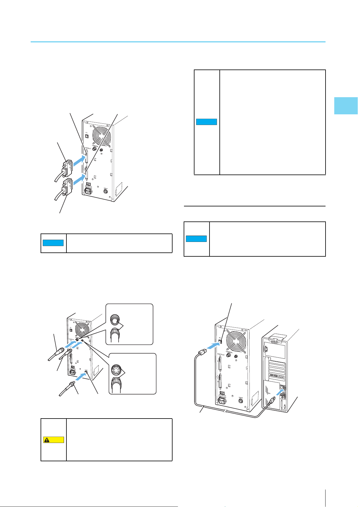
Connection Procedure
Connecting the microscope unit and
control unit
Set-Up
Turn off the power to the control unit and
control PC before connecting the cables.
Connecting cables while the power is on could
cause product failure.
1 Connect the controller A cable/B cable to the con-
troller A connector/B connector located on the side
of the microscope unit.
NOTICE
• Inserting the cables in the wrong
orientation may cause the connector
pins to break.
• Do not use too much force when
connecting cables, as this can break the
connector pins.
• Any dust or dirt on the connector face of
the fiber optic cable ends may cause
degradation of the cable.
• When connecting the cable, use caution
not to mistake the control unit side for
the measurement unit side. Doing so
may cause damage.
NOTICE
Use screws to secure the connectors once
they are connected.
2 Connect the fiber optic cable to the LIGHT connec-
tor on the side of the microscope unit, with the cam-
era cable to the CAMERA connector and the SCAN
CONTROL cable to the SCAN CONTROL connector.
2-6
VK-X100K/X200K User’s Manual
3 Hold the cables with the cord hook after connected.
Page 37
Connections
2
Controller
A Cable
CONTROLLER
A Connector
CONTROLLER
B Connector
Controller B Cable
NOTICE
Camera
Cable
Fiber Optic
Cable
CAMERA Connector
LIGHT Connector
Insert with
the cut-outs
aligned.
Insert with
the ridge and
the valley
aligned.
SCAN CONTROL
Connector
SCAN
CONTROL
Cable
CAUTION
NOTICE
USB
Cable
Control Unit
(VK-X100K/X200K)
PC Connector
Control
PC
4 Connect the CONTROLLER A cable/B cable to the
controller A connector/B connector located on the
rear of the microscope unit.
Use screws to secure the connectors once
they are connected.
• Inserting the cables in the wrong
orientation may cause the connector
pins to break.
• Do not use too much force when
connecting cables, as this can break the
connector pins.
NOTICE
• Any dust or dirt on the connector face of
the fiber optic cable ends may cause
degradation of the cable.
• Turn off the power to the control unit
before connecting the cables. Connect-
ing cables while the power is on could
cause product failure.
Connecting the control unit to the control
PC
Connect the USB cable to the USB connector
located at the rear of the Control PC. Connect-
ing to the front USB connector of the control PC
may make the communication unstable.
Set-Up
5 Connect the fiber optic cable to the LIGHT connec-
tor on the side of the microscope unit, with the cam-
era cable to the CAMERA connector and the SCAN
CONTROL cable to the SCAN CONTROL connector.
The SCAN CONTROL connector is high
voltage (150V DC). Do not connect other
than the provided SCAN CONTROL cable
of the VK-X100K/X200K Series. An
electric shock or malfunction may occur.
VK-X100K/X200K User’s Manual
1
Connect the USB cable to PC connector on the back
of the control unit and to the USB connector on the
back of the control PC.
2-7
Page 38

Connections
2
NOTICE
NOTICE
For two-prong outlets
Conversion
adapter
AC power supply
cable
Grounding line
Grounding
screws
For three-prong outlets
CAUTION
Connecting the control PC and the
peripherals
Connect the control PC and the peripherals
Set-Up
with the power of the control unit and the
control PC turned off. Connecting cables while
the power is on could cause product failure.
1 Connect the display, keyboard and mouse to the
control PC.
“Connection Diagram” (Page 2-4)
Connecting the power
Connect the control unit, the control computer and the dis-
play to an AC power source once all of the devices are con-
nected.
Make sure that the power turned off on the
control unit and the control PC etc., when
connecting the AC power cable. Connecting
cables while the power is on could cause
product failure.
1 Connect AC power cable to the control unit and the
control PC.
“Connection Diagram” (Page 2-4)
2 Connect the cables of the control unit, the control
PC and the display to an AC power source.
• Make sure that the earth terminal (the
earth wire) of the AC power cable is
grounded. Otherwise, an electric shock
or malfunction may occur.
• If the AC power source is a two-prong
outlet, connect the cable using the
supplied 3 to 2 conversion adapter. In
such a case, be sure to ground the earth
cable.
2-8
VK-X100K/X200K User’s Manual
Page 39

Chapter
3
3
Before Measuring
This chapter describes the preparation and basic
adjustments to be made before taking measure-
ments.
Before Measuring
Sequence of Preparation before Measuring...........Page 3-2
Startup and Shutdown ...........................................Page 3-3
Measurement Basics (For Proper Measurement) ..Page 3-5
Adjusting the Measurement Unit ............................Page 3-8
VK-X100K/X200K User’s Manual
3-1
Page 40

3
Sequence of Preparation before Measuring
1st Observation/Measurement
Turn on the power of the control unit and the control PC. Turn the power of the
control unit on at least 60 minutes or more before starting the measurement.*
“Starting Up the System” (Page 3-3)
2nd Observation/Measurement
After starting the Observation Application, initialize the lens position
(Returning to the origin).
“Initializing Lens Position” (Page 3-8)
Use the Observation Application to observe/measure the sample.
“VK-X100K/X200K Observation/Image Assembling Application Reference Manual”
Place the sample on the rotating stage for observation/measurement.
“Loading the sample” (Page 3-9)
Turn the revolver to select the objective lens.
“Selecting magnification” (Page 3-9)
Turn the X axis stage handle and Y axis stage handle to move the sample to the observation position.
“Adjusting the observation position” (Page 3-10)
Turn the focusing handle to adjust the focus.
“Adjusting the focus” (Page 3-10)
Use the APERTURE SHUTTER (Aperture iris shutter) to adjust the intensity of the illumination.
“Adjusting brightness” (Page 3-11)
Starting Up the System
Observation/Measurement
Adjusting Brightness
Adjusting the Focus
Adjusting the Observation Position
Selecting Magnification
Loading the Sample
Initializing Lens Position
Before Measuring
* Wait one hour after turning on the power of the control unit before taking measurements.
Measurements may fluctuate with the default drift if the temperature of the device is not stable.
3-2
VK-X100K/X200K User’s Manual
Page 41

3
Startup and Shutdown
Point
Lit in Orange
POWER
Switch OFF
POWER
Switch ON
Starting Up the System
1 If the power is not on, turn on the main power switch
located on the rear of the control unit.
When the POWER switch on the front of the
control unit is lit in orange, the power is
already on. No operation to switch the main
power switch on the rear is required.
Turn the power of the control unit on at
Important
least 60 minutes or more before starting
the measurement.
To prevent fluctuations in measurements
caused by the default drift with the
internal temperature kept stable, 60
minutes or more of the pre-heating time is
required.
3 When using the electric X-Y stage (VK-S100K/S105/
S110), turn the power for the stage driver on.
“Special Electric X-Y Stage VK-S100K/S105/S110
for 3D Laser Scanning Microscope User’s Manual”
4 Turn on the power for the control PC.
Before Measuring
2 Turn on the POWER switch located on the front of
the control unit.
The POWER switch light changes into green with the
LASER ON (Laser radiation emission warning) lit.
VK-X100K/X200K User’s Manual
Reference
• While the control unit and the control PC
may be turned on in a different order, it will
take several seconds for communication
to be established after the control PC rec-
ognizes the control unit.
• Log into the control PC using administra-
tor privileges.
3-3
Page 42

Startup and Shutdown
3
POWER
Switch ON
POWER
Switch OFF
Reference
Shutting Down the System
1 Shut down Windows.
The control PC power turns off.
2 Turn off the POWER switch on the front of the con-
trol unit.
Before Measuring
The LASER ON (Laser radiation emission warning)
goes off with the POWER switch light changed to
orange.
You do not need to turn off the main power
every time you finish operation. Turn the
main switch on the rear of the control unit off
when the unit will not be used for a long time
or when you are transporting the unit.
3-4
VK-X100K/X200K User’s Manual
Page 43

3
Measurement Basics (For Proper Measurement)
This section describes what you need to know before taking measurements.
A Variety of the Standard Objective Lens and How to Select One
In VK-X105/X110/X210, each has the following 4 types of the standard objective lenses to mount. Select them according to
their use.
Model Standard objective lenses Depth of
Field
(µm)*
VK-X105 CF IC EPI Plan 5X 38.9 7.47 Aligning the Position for
CF IC EPI Plan 10X 7.31 17.5
CF IC EPI Plan 20X 3.11 27.4 Shape and Film Thickness
CF IC EPI Plan 50X 1.03 53.1
VK-X110 CF IC EPI Plan 10X 7.31 17.5 Aligning the Position for
CF IC EPI Plan 20X 3.11 27.4
CF IC EPI Plan 50X 1.03 53.1 Shape and Film Thickness
CF IC EPI Plan 100X 0.73 71.8 X
VK-X210 CF IC EPI Plan 10X 4.53 17.5 Aligning the Position for
CF IC EPI Plan 20X 1.91 27.4 Shape and Film Thickness
CF IC EPI Plan Apo 50X 0.45 71.8
CF IC EPI Plan Apo 150X 0.45 71.8 X
*1
This is the depth of field in the laser images. The values listed above are theoretical values.: Suited to the measurement.
1
Angle char-
acteristics
Plane
measure-
ments
Width
measure-
ment
Height
measure-
ment
X
Film thick-
ness mea-
surement
: May be used depending on the condition.
: Cannot be used for measurement.
Main use (Yardstick)
Measurement
Measurement
Measurement
Measurement
Measurement
Measurement
Before Measuring
Points for selecting the lens
When measuring the height in high precision
Under normal circumstances, the standard 50x, 100x
and 150x objective lenses are suited to height measure-
ments.
In the measurement unit using confocal laser optics, the
shallower the depth of field (range when the image is
focused) of the objective lens, the better the repeat accu-
racy.
The highest magnification lens possible should be used
for high-resolution height images.
VK-X100K/X200K User’s Manual
For measurements with a long Z measurement
distance
The VK-X100K/X200K Series can set up to 7 mm in the Z
measurement distance. However, when performing
actual measurements, the size of the objective lens you
are using will dictate the measurable Z measurement dis-
tance.
When taking measurements with broad Z measurement
distance, it is recommended that you use the 10x or 20x
objective lenses or lenses available on the market (long
range or ultra-long range lenses).
For high-resolution plane or width
measurements
Plane measurements can be carried out with any stan-
dard objective lens.
When taking plane measurements, the narrower the field
of view, the higher the resolution. Additionally, setting the
measurement quality to super-fine detail will allow you to
3-5
Page 44

Measurement Basics (For Proper Measurement)
3
Point
Far
Distance from
objective lens
Near
Front peak
Rear peak
Low
High
Received light intensity
read high-resolution images even with a low magnifica-
tion lens.
For a large area plane measurement
Under normal circumstances, the standard 10x and 20x
objective lenses are suited for plane measurements.
About the long range/ultra-long range
Before Measuring
objective lenses
When a long focal distance (Z measurement distance) is
preferred, long range/ultra-long range lenses on the market
may be used. Select the best objective lens according to
the size and shape of the sample.
Some functions may not be available for mea-
surement of the film thickness of a transparent
object (top surface) etc. For more details, contact
our Sales Dept.
Objective lens*1 Monitor
magnification
Long distance
20X
Long distance
50X
Long distance
100X
Ultra-Long
distance 20X
Ultra-Long
distance 50X
Ultra-Long
distance 100X
*1 All of these lenses are made by Nikon.
*2 Depending on differences between the individual lenses, the
operating distance may be smaller than the above stated
values. Make a judgement upon confirming the actual
conditions.
400X 11.0 mm 0.4
1000X 8.7 mm 0.55
2000X 2.0 mm 0.8
400X 20.5 mm 0.35
1000X 13.8 mm 0.45
2000X 4.7 mm 0.73
Operating
distance*
2
aperture (N.A.)
Numerical
Correction in the Film Thickness Measurement
There will be two focal points when measuring transparent
samples, one in front and one behind. This means that the
photoreceptor will also see two peaks. The VK-X100K/
X200K Series can measure the thickness of a film by mea-
suring the distance between those two peaks.
The value returned when measuring film thickness may be
less than the actual thickness due to the refractive index of
the material. These errors can be corrected by inputting the
value for a master sample.
“
For the error correction method, refer to
X200K Observation/Image Assembling Application Refer-
ence Manual.”
VK-X100K/
3-6
VK-X100K/X200K User’s Manual
Page 45

3
Adjusting the Positions of the Laser and the Camera
This feature allows you to correct for displacement of the
camera or laser due to transportation or changes in temper-
ature. These adjustments should be performed when regis-
tering a new lens or when you notice that the color or light
intensity in color images are misaligned.
For the position adjustment method, refer to
X200K Observation/Image Assembling Application Refer-
ence Manual.”
“VK-X100K/
Measurement Basics (For Proper Measurement)
Before Measuring
VK-X100K/X200K User’s Manual
3-7
Page 46
3
Adjusting the Measurement Unit
Important
NOTICE
Fine Coarse
<1>
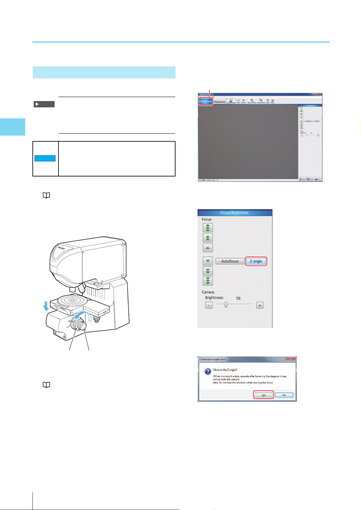
Initializing Lens Position
Initialize the lens position (“Returning to the origin”).
It is recommended that you initialize the lens
position once per day when starting up the
system. The lens position does not need to be
initialized after each measurement.
Before Measuring
When initializing the lens position, do not place
the sample on the rotating stage.
Contact between the objective lens and the
sample could damage either one.
1 Start the system.
“Starting Up the System” (Page 3-3)
2 Turn the focusing handle (Coarse/Fine) to lower the
X-Y stage to the lowest level possible.
4 Select the [Observe] tab (<1>) in the tool bar.
5 Click the [Z origin] button.
3 Start the Observation Application.
“VK-X100K/X200K Observation/Image Assembling
Application Reference Manual”
3-8
6 Click [Yes] in the confirmation message.
The revolver moves up/down automatically with the
objective lens moving to the Z origin.
VK-X100K/X200K User’s Manual
Page 47

Adjusting the Measurement Unit
3
NOTICE
Revolver
Adjustment of the Observation Position/Magnification
Loading the sample
1 Place the sample to be observed on the rotating
stage.
Selecting magnification
1 Turn the revolver manually, selecting the objective
lens preferred for the observation.
Do not bring the sample into contact with
NOTICE
the objective lens when turning the
revolver.
Doing so may cause failure.
Before Measuring
Reference
The standard X-Y stage can accommodate
samples up to 28 mm in height and 5 kg in
weight.
If the sample height is larger than what can
be accommodated by the standard stage, it
is recommended that you install an optional
spacer or stand.
“Mounting the Spacer for the VK-X210”
(Page 4-7)
“Mounting the Spacer for the VK-X105/
X110” (Page 4-12)
“Mounting the Stand for VK” (Page 4-20)
VK-X100K/X200K User’s Manual
3-9
Page 48

Adjusting the Measurement Unit
3
Left and right motion
Forward and backward motion
Fine Coarse
Adjusting the observation position
1 Turn the X axis stage handle (left/right) and Y axis
stage handle (forward/back) to move the sample to
the observation position.
Before Measuring
Adjusting Focus/Brightness
Adjusting the focus
1 Turn the focusing handle (Coarse/Fine) to adjust the
focus.
Handle Maximum
X axis stage handle
(left/right movement)
Y axis stage handle
(Front/Back
movement)
Distance covered
movement
range
70 mm 18 mm
70 mm 36 mm
by one rotation of
the dial
Handle Distance
adjusted
Focusing handle (Coarse) Approx. 3.3 mm
/ turn
Focusing handle (Fine) 2 μm/scale
Do not bring the sample into contact with
NOTICE
the objective lens when moving the X-Y
stage up/down. Doing so may cause
failure.
Maximum
movement
range
Approx. 28 mm
3-10
VK-X100K/X200K User’s Manual
Page 49

3
Adjusting brightness
APERTURE SHUTTER
For VK-X210
1 Push (or pull) the APERTURE SHUTTER (Aperture
iris shutter) to adjust the intensity of the illumina-
tion.
Adjusting the Measurement Unit
Before Measuring
Reference
• To obtain the best images possible with
5x, 10x, 20x objective lens, keep the
APERTURE SHUTTER open (by pressing
and holding it) and use the shutter speed
to adjust the brightness.
•
When using the 100x or 150x objective
lenses, use the APERTURE SHUTTER to
adjust brightness. Chances are that there
may be flares in the image if the aperture
shutter is fully open (too bright).
VK-X100K/X200K User’s Manual
3-11
Page 50

Adjusting the Measurement Unit
3
Before Measuring
MEMO
3-12
VK-X100K/X200K User’s Manual
Page 51

Chapter
4
4
Mounting Optional
Devices
This chapter describes the optional devices and
how to install them.
Mounting Optional Devices
List of Optional Devices .........................................Page 4-2
Removing/Mounting the Measurement Unit...........Page 4-4
Mounting the Spacer for the VK-X210 ...................Page 4-7
Mounting the Spacer for the VK-X105/X110......... Page 4-12
Mounting a 300 mm Wafer X-Y Stage ................. Page 4-17
Mounting the Stand for VK...................................Page 4-20
VK-X100K/X200K User’s Manual
4-1
Page 52

4
List of Optional Devices
Optional devices
Name Model Number Function
Spacers (4 pieces)
OP-51426 Use this when the sample is taller than can be
viewed on a standard setup. The height can be
adjusted by a combination of spacers.
This spacer is for the VK-X210.
Spacers (4 pieces) OP-38162 Use this when the sample is taller or broader
than can be viewed on a standard setup. The
height and the area can be adjusted by a
combination of spacers.
This spacer is for the VK-X105/X110.
Stand OP-82693 Allows the measurement unit to change height
by up to 100 mm when installed on the back of
the microscope.
300 mm wafer X-Y stage OP-51498 A simple manual stage that allows wafers of 300
mm in diameter, LCD panels, circuit boards and
other similar objects to be observed easily.
Electric X-Y Stage VK-S100K
VK-S105
VK-S110
Swaps out for the standard X-Y stage when
using the automatic image assembling function
of the Image Assembling application.
Anti-vibration Stand 971672
TAPC -4 5
Installing the microscope on an anti-vibration stand
will improve its stability when exposed to vibration
(made by TOKKYOKIKI CORPORATION).
Continue to next
page
In the VK-X100K/X200K Series, the following optional devices are available.
Contact your nearest KEYENCE office for more details.
Mounting Optional Devices
4-2
VK-X100K/X200K User’s Manual
Page 53

List of Optional Devices
4
Application
Name Model Number Function
Image Assembling Application VK-H1XJ Composes a single large image by image
processing from a series of images measured by
the Observation Application.
When combined with the electric X-Y stage, this
allows continuous measurement by automatic
control.
Particle Analysis Module VK-H1XG Extends the functionality of the Analysis
Application. This application allows
measurement of the number as well as the area
and length of the object particle, statistical
processing of data etc.
Measurement Analysis Module VK-H1XP Extends the functionality of the Analysis
Application. Automatic correction such as for
uneven objects, measurement of volume,
surface area, circumference, spherical
curvature, plane angles, as well as observation
position using a template etc., can be made.
ISO-25178 Surface Texture
Measurement Module
VK-H1XR Extends the functionality of the Analysis
Application. This application allows
measurement of ISO-25178 surface texture.
Continued from
previous page
Mounting Optional Devices
VK-X100K/X200K User’s Manual
4-3
Page 54

4
Removing/Mounting the Measurement Unit
CAUTION
NOTICE
Point
Cord Hook
M4 Bolt
M5 Bolt
When mounting the spacer (OP-38162/51246) and stand
(OP-82693), the measurement unit must be removed from
the pedestal of the microscope. This section describes how
to remove/install the measurement unit.
The measurement unit weighs approx. 8.5 kg
for the VK-X105/X110 and approx. 10 kg for the
VK-X210. Only place the device on stable,
sturdy, level surfaces to prevent the device
from falling and being damaged.
3 Remove the four bolts that secure the measurement
unit and the pedestal.
Mounting Optional Devices
Work with the objective lenses and cables
removed from the measurement unit.
Have a hexagonal wrench (M4/M5) ready to
remove/install bolts.
Removing the Measurement Unit
1 Confirm all of the objective lenses and cables are
removed.
2 Remove the cord hook bolts that secure the cord
hook from the side of the measurement unit, remov-
ing the cord hook.
The bolts are required for mounting the
Important
measurement unit when the spacer (OP-
38162/51246) and stand (OP-82693) are
removed. Be sure to keep them in a
secure location.
4 Remove the measurement unit from the pedestal.
4-4
VK-X100K/X200K User’s Manual
Page 55

Removing/Mounting the Measurement Unit
4
NOTICE
Revolver
NOTICE
• To remove the measurement unit, hold
the narrow part on the front and the
indentation on the back of the unit, then
lift it off of the pedestal.
• Do not lift the measurement unit by
holding the revolver handle. Doing so
may cause failure.
Conditions for Mounting the Measurement Unit
When removing the measurement unit in order to use it
mounted on the equipment and pedestal, confirm that the
mounting position of the measurement unit meets the fol-
lowing conditions.
• The mounting panel is made of aluminum, stainless steel
or iron with a thickness of 12 mm or more.
• 4 places on the side or back of the measurement unit are
fixed to the mounting panel by M6 screws made of stain-
less steel or iron.
When used in an environment with positive
grounding, an insulated mount is
recommended.
Mounting Optional Devices
VK-X100K/X200K User’s Manual
4-5
Page 56
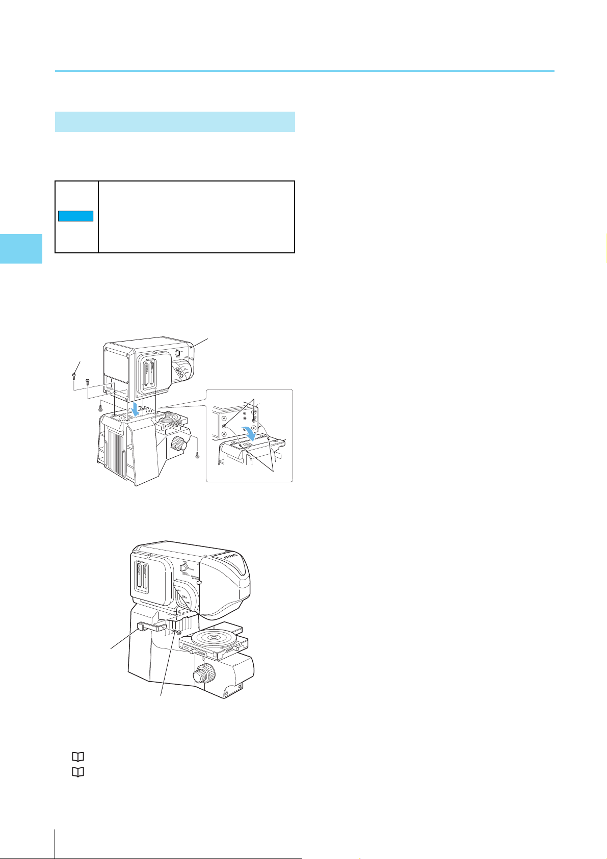
Removing/Mounting the Measurement Unit
4
NOTICE
Measurement Unit
Hole Position
Positioning Pin
M5
Bolt
Cord Hook
M4 Bolt
Mounting the Measurement Unit
After the spacer (OP-38162/51246) and the stand (OP-
82693) are removed, mount the measurement unit.
When removing the spacer (OP-38162/51246)
and stand (OP-82693) and mounting the
measurement unit, work with the objective
lenses and cables removed from the
measurement unit.
Mounting Optional Devices
1 Reconnect the removed measurement unit to the
pedestal by affixing the four connecting bolts.
When mounting, align the holes on the bottom of the
measurement unit with the fixing pins on the pedestal.
2 Attach the cord hook.
3 Mount the objective lenses and connect the cables.
“Mounting the Objective Lenses” (Page 2-3)
“Connections” (Page 2-4)
4-6
VK-X100K/X200K User’s Manual
Page 57

4
Mounting the Spacer for the VK-X210
Point
Spacer 2
Spacer 1
Mounting the spacer (OP-51426) on the VK-X210 allows for
observation of samples that are taller than the standard
specifications.
The spacer (OP-51426) is an option for the VK-
X210. It cannot be used with other models.
Package List
The spacer (OP-51426) consists of the following parts.
Spacer 1: 1 piece
H 208×W 195×T 12 mm
Spacer 2: 1 piece
How to Use the Spacer
There are three ways to adjust the vertical clearance using
the spacers for the VK-X210, as follows.
• Adjusting the height by 24 mm
Combine spacer 1 and spacer 2.
• Adjusting the height by 49 mm
Combine spacer 1, spacer 2 and spacer 3.
• Adjusting the height by 74 mm
Combine spacer 1, spacer 2 and spacer 3 (2 pieces).
Mounting Optional Devices
Adjusting the height by 24 mm: Spacer 1 +
spacer 2
Combining spacers 1, and 2 (2 pieces) increases the verti-
cal clearance by 24 mm.
Spacers 1 and 2 must be used together.
H 208×W 195×T 12 mm
The area and thickness are the same as those of spacer 1, but
the shape is different.
Spacer 3: 2 pieces
H 186×W 155×T 25 mm
Smaller area than spacer 1/2, but thicker.
Stainless Steel Hexagon Socket Bolts
M6 length 15 mm: 4 pieces
M6 length 20 mm: 4 pieces
M6 length 40 mm: 2 pieces
M6 length 50 mm: 2 pieces
M6 length 65 mm: 2 pieces
M6 length 75 mm: 2 pieces
Stainless Steel Hexagon Socket Bolts with Washer
M6 length 25 mm: 4 pieces
Plain Stainless Steel Washers
Size M6: 10 pieces
Bolts and washers to use
Name Description How to use
Stainless Steel
Hexagon Socket
Bolts
Stainless Steel
Hexagon Socket
Bolts with Washer
Stainless steel round
plain washer
M6 length
15 mm: 4
pieces
M6 length 20
mm: 4 pieces
M6 length
25 mm: 4
pieces
Size M6: 8
pieces
Fastening spacer 1 to the
measurement unit
Fixing spacer 2 and the
pedestal 2 pieces
Fixing spacer 1 and
spacer 2 2 pieces
Fixing spacer 2 and
spacer 1 2 pieces
Fastening spacer 1 to the
measurement unit
Fixing the pedestal and
spacer 2 2 pieces
M6 not used for 25 mm
bolt.
2 pieces
2 pieces
VK-X100K/X200K User’s Manual
4-7
Page 58

Mounting the Spacer for the VK-X210
4
M6 length 25 mm
M6 length
20 mm
Spacer 1
M6 length
25 mm
M6 length 15 mm
Spacer 2
M6 length
15 mm
M6 length 20 mm
Spacer 1
Spacer 2
Spacer 3
Mounting Optional Devices
Height adjustment by 49 mm: Spacer 1 +
spacer 2 + spacer 3
Combining spacers 1, 2 and 3 increases the vertical clear-
ance by 49 mm.
Bolts and washers to use
Name Description How to use
Stainless Steel
Hexagon Socket
Bolts
Stainless Steel
Hexagon Socket
Bolts with Washer
Stainless steel round
plain washer
M6 length
15 mm: 2
pieces
M6 length 20
mm: 4 pieces
M6 length
40 mm: 2
pieces
M6 length
50 mm: 2
pieces
M6 length
25 mm: 2
pieces
Size M6: 10
pieces
Fastening spacer 1 to the
measurement unit
Fixing spacer 1 and
spacer 2 2 pieces
Fixing spacer 2 and
spacer 1 2 pieces
Fixing spacers 2 and 3 to
the pedestal
Fixing spacers 3 and 2 to
the pedestal
Fastening spacer 1 to the
measurement unit
M6 not used for 25 mm
bolt
4-8
VK-X100K/X200K User’s Manual
Page 59

Mounting the Spacer for the VK-X210
4
M6 length 25 mm
M6 length
20 mm
Spacer 1
M6 length
40 mm
M6 length 15 mm
Spacer 2
M6 length
50 mm
M6 length 20 mm
Spacer 3
Spacer 1
Spacer 2
Spacer 3 (2 pieces)
Height adjustment by 74 mm: Spacer 1 +
spacer 2 + spacer 3 (2 pieces)
Combining spacers 1, 2 and 3 (2 pieces) increases the ver-
tical clearance by 74 mm.
Bolts and washers to use
Mounting Optional Devices
Name Description How to use
Stainless Steel
Hexagon Socket
Bolts
Stainless Steel
Hexagon Socket
Bolts with Washer
Stainless steel round
plain washer
M6 length
15 mm: 2
pieces
M6 length 20
mm: 4 pieces
M6 length
65 mm: 2
pieces
M6 length
75 mm: 2
pieces
M6 length
25 mm: 2
pieces
Size M6: 10
pieces
Fastening spacer 1 to the
measurement unit
Fixing spacer 1 and
spacer 2 2 pieces
Fixing spacer 2 and
spacer 1 2 pieces
Fixing spacers 2 and 3 (2
pieces) to the pedestal
Fixing spacers 3 (2
pieces) and 2 to the
pedestal
Fastening spacer 1 to the
measurement unit
M6 not used for 25 mm
bolt
VK-X100K/X200K User’s Manual
4-9
Page 60

4
M6 length 25 mm
M6 length
20 mm
Spacer 1
M6 length
65 mm
M6 length 15 mm
Spacer 2
M6 length
75 mm
M6 length 20 mm
Spacer 3
Point
Mounting the Spacer for the VK-X210
Mounting Optional Devices
Mounting Spacers
The measurement unit weighs approx. 8.5 kg
for the VK-X105/X110 and approx. 10 kg for VK-
CAUTION
Required items
• Take the necessary number of bolts and plain washers
out according to the number of the spacers to be
mounted.
For the number of spacers, bolts and plain washers,
refer to “How to Use the Spacer” (Page 4-7).
• Have hexagonal wrenches (M5/M6/M8) ready.
How to mount
X210. Only place the device on stable, sturdy,
level surfaces to prevent the device from
falling and being damaged.
Here we will explain the case to use spacer 1, spacer 2 and
spacer 3 (2 pieces) as an example.
• When mounting a bolt, insert washer (except for
M6 length 25 mm).
• When using spot-faced holes (bolt mounting
hole), no washers are required.
1 Remove the measurement unit.
“Removing the Measurement Unit” (Page 4-4)
2 After aligning the holes on the measurement unit
over the pins for positioning of spacer 1, install M6
bolt of 15 mm (x2) and M6 bolt of 25 mm (x2).
4-10
VK-X100K/X200K User’s Manual
Page 61
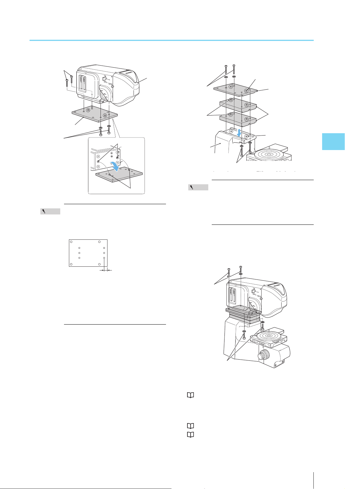
4
• The spacer is placed so that the edge from
Spacer 1
Measurement Unit
Positioning Hole
Positioning Pin
M6 length 25 mm
M6 length 15 mm
Point
Front
Short
Positioning Pin
Spacer 2
Spacer 3
M6 length 75 mm
M6 length
65 mm
Positioning
Pin
Positioning Pin
Pedestal
M6 length 20 mm
M6 length 20 mm
which the distance to the positioning pins is
shorter, faces the front of the device
(toward the objective lens).
Mounting the Spacer for the VK-X210
• Begin with spacer 2 to fix to the pedestal
Point
with M6 length 65 mm bolt (x2).
• Begin with the pedestal to fix spacer 3 (x2)
and spacer 2 with M6 length 75 mm bolt
(x2).
4 After aligning the positioning holes on spacer 1
over the positioning pins for on spacer 2, install M6
bolt of 20 mm (x4) to fix .
Mounting Optional Devices
•Begin with spacer 1 to affix to the measure-
ment unit with M6 length 15 mm bolt.
•Begin with the measurement unit to affix
spacer 1, with M6 length 25 mm bolt (2
pieces).
3 Install spacer 3 (2 pieces) and then spacer 2 in order
on the pedestal by aligning the positioning pin to
positioning hole and fix with M6 65 mm bolt (2
pieces) and M6 75 mm bolt (2 pieces).
5 Attach the cord hook.
“Mounting the Measurement Unit” (Page 4-6)
6 Mount the objective lenses and connect the cables.
“Mounting the Objective Lenses” (Page 2-3)
“Connections” (Page 2-4)
VK-X100K/X200K User’s Manual
4-11
Page 62

4
Mounting the Spacer for the VK-X105/X110
Point
Mounting the spacer (OP-38162) on the VK-X105/X110
allows for observation of samples taller than the standard
specifications.
Spacer (OP-38162) is optional for the VK-X105/
X110. It cannot be used with other models.
Package List
Spacer (OP-38162) consists of the parts below.
Spacer 1 (Top panel): 1 piece
Mounting Optional Devices
H 175×W 185×T 12 mm
Spacer 2 (middle panel): 2 pieces
H 175×W 185×T 25 mm
The area and the height are the same as for spacer 1, but with
approx. twice as much in thickness.
Spacer 3 (Bottom panel): 1 piece
H 175×W 280×T 12 mm
The thickness is the same as for spacer 1, but with different
area.
How to Use the Spacer
There are three ways as follows to adjust the vertical clear-
ance using a spacer for the VK-X105/X110.
• Pattern A - Adjusting the height of the measurement unit
For use with a tall sample.
• Pattern B - Adjusting the position of the measurement
unit.
For use with a sample wider than X-Y stage.
• Pattern C - Adjusting the orientation of the measurement
unit.
For use with a sample unable to place on X-Y stage.
Pattern A - Adjusting the height of the
measurement unit
For use with a tall sample. Adjust the height of the measure-
ment unit with a combination of spacers 1 to 3.
Spacers 1 and 3 must be used together. Spacer 2 is used
in necessary number of pieces.
Stainless Steel Hexagon Socket Bolts
M6 length 15 mm: 2 pieces
M6 length 20 mm: 2 pieces
M6 length 25 mm: 4 pieces
M8 length 25 mm: 4 pieces
M8 length 50 mm: 4 pieces
M8 length 75 mm: 4 pieces
Plain Stainless Steel Washers
Size M6: 8 pieces
Size M8: 8 pieces
Stainless Steel Round Spring Washer
Size M6: 8 pieces
Size M8: 8 pieces
Bolts and washers to use
Name Description How to Use
Stainless Steel
Hexagon Socket
Bolts
M6 length
15 mm: 2
pieces
M6 length 20
mm: 2 pieces
M6 length
25 mm: 4
pieces
M8 length
75 mm: 4
pieces
Fastening spacer 1 to the
measurement unit
Fixing spacer 3 and the
pedestal
Fastening spacer 1 to the
measurement unit
Fixing the pedestal and
spacer 3 2 pieces
Fixing spacer 3 and
spacer 1 2 pieces
Fixing spacer 1 and
spacer 3 2 pieces
2 pieces
4-12
VK-X100K/X200K User’s Manual
Page 63

Mounting the Spacer for the VK-X105/X110
4
M6 length
25 mm +
spring
washer +
plain washer
M8 length 75 mm
+ spring washer + plain washer
Spacer 1
M6 length 20 mm
+ spring washer
Spacer 3
M6 length
15 mm
+ spring
washer
Spacer 2
M8 length 75 mm
+ spring washer
+ plain washer
M6 length 25 mm
+ spring washer
+ plain washer
Stainless steel round
plain washer
Stainless steel
spring washers
Size M6: 4
pieces
Size M8: 4
pieces
Size M6: 8
pieces
Size M8: 4
pieces
Pattern B - Adjusting the position of the
measurement unit
For use with a sample wider than X-Y stage. Adjust the posi-
tion of the measurement unit with a combination of spacers
1 and 3.
Bolts and washers to use
Name Description How to Use
Stainless Steel
Hexagon Socket
Bolts
Stainless steel round
plain washer
Stainless steel
spring washers
M6 length
15 mm: 2
pieces
M6 length 20
mm: 2 pieces
M6 length
25 mm: 4
pieces
M8 length
25 mm: 4
pieces
Size M6: 4
pieces
Size M8: 4
pieces
Size M6: 8
pieces
Size M8: 4
pieces
Fastening spacer 1 to the
measurement unit
Fixing spacer 3 and the
pedestal
Fastening spacer 1 to the
measurement unit
2 pieces
Fixing the pedestal and
spacer 3 2 pieces
Fixing spacer 3 and
spacer 1 2 pieces
Fixing spacer 1 and
spacer 3 2 pieces
Mounting Optional Devices
VK-X100K/X200K User’s Manual
4-13
Page 64

Mounting the Spacer for the VK-X105/X110
4
M8 length 75 mm + spring washer + plain washer
M6 length 25 mm
+ spring washer
+ plain washer
Spacer 1
M6 length 20 mm
+ spring washer
Spacer 3
M6 length 75 mm
+ spring washer + plain washer
M6 length 15 mm
+ spring washer
M6 length 25 mm
+ spring washer
+ plain washer
M8 length 75 mm
+ spring washer
+ plain washer
M6 length 15 mm
+ spring washer
Spacer 1
Spacer 2
Spacer 3
M6 length 25 mm
+ spring washer
+ plain washer
M6 length 20 mm
+ spring washer
M8 length 75 mm
+ spring washer
+ plain washer
M6 length 25 mm
+ spring washer
+ plain washer
Mounting Optional Devices
Pattern C - Adjusting the orientation of the
measurement unit
For use with a sample unable to place on the X-Y stage.
Adjust the orientation of the measurement unit with a com-
bination of spacers 1 and 3.
Bolts and washers to use
Name Description How to Use
Stainless Steel
Hexagon Socket
Bolts
Stainless steel round
plain washer
Stainless steel
spring washers
M6 length
15 mm: 2
pieces
M6 length 20
mm: 2 pieces
M6 length
25 mm: 4
pieces
M8 length
75 mm: 4
pieces
Size M6: 4
pieces
Size M8: 4
pieces
Size M6: 8
pieces
Size M8: 4
pieces
Fastening spacer 1 to the
measurement unit
Fixing spacer 3 and the
pedestal
Fastening spacer 1 to the
measurement unit
Fixing the pedestal and
spacer 3 2 pieces
Fixing spacer 3 and
spacer 1 2 pieces
Fixing spacer 1 and
spacer 3 2 pieces
2 pieces
4-14
VK-X100K/X200K User’s Manual
Page 65
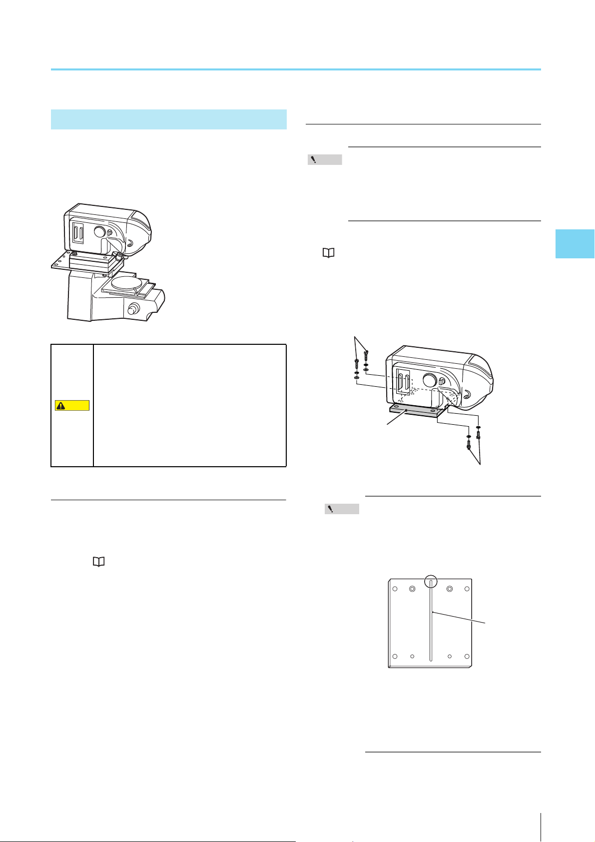
Mounting the Spacer for the VK-X105/X110
4
CAUTION
Point
M6 length 25 mm + spring washer + plain washer
Spacer 1
M6 length 15 mm + spring washer
The Groove
Where the
Positioning
Pin Is Set
The shorter side faces the front of the device
(toward the objective lens)
Mounting Spacers
This portion uses the spacer with pattern A as an example
of installing spacers. When selecting other pattern, refer to
the combinations on the previous page and work accord-
ingly.
The measurement unit weighs approx. 8.5 kg
for the VK-X105/X110 and approx. 10 kg for the
VK-X210. Spacers are heavy. Only place the
device on stable, sturdy, level surfaces to
prevent the device from falling and being
damaged. Moving the center of gravity of the
microscope unit too far forward may cause the
microscope to fall and cause injury or
damage.
How to mount
When installing bolts, for a place where both of
the spring washer and the plain washer are used,
put the spring washer through the bolt first (line
up in the order of bolt head - spring washer -
installation position).
1 Remove the measurement unit.
“Removing the Measurement Unit” (Page 4-4)
2 Install spacer 1 on the measurement unit with M6
bolt of 15 mm (x2) and M6 bolt of 25 mm (x2).
Mounting Optional Devices
Required items
• Take the necessary number of bolts and washers out
according to the number of the spacers to be mounted.
As for the number of spacers, bolts, and plain washers,
refer to “How to Use the Spacer” (Page 4-12).
• Have hexagonal wrenches (M5/M6/M8) ready.
• The spacer is placed so that the edge from
Point
which the distance to the positioning pins is
shorter, faces the front (toward the objec-
tive lens).
• Begin with spacer 1 to affix to the measure-
ment unit with M6 15 mm long bolt.
• Begin with spacer 1 to affix to the measure-
ment unit with M6 25 mm long bolt (2x) and
spring washer + plain washer.
VK-X100K/X200K User’s Manual
4-15
Page 66

Mounting the Spacer for the VK-X105/X110
4
M6 length 20 mm + spring washer
Spacer 3
M6 length 25 mm + spring washer + plain washer
Point
M8 length 75 mm + spring washer + plain washer
Spacer 1
Spacer 2
Spacer 3
M8 length 75 mm + spring washer + plain washer
3 Install spacer 3 on the measurement unit with M6
bolt of 20 mm (x2) and M6 bolt of 25 mm (x2).
Mounting Optional Devices
• Begin with spacer 3 to affix to the measure-
ment unit with M6 20 mm long bolt (2x).
• Begin with the pedestal to affix to the
spacer 3 with M6 25 mm long bolt (2x) and
spring washer + plain washer.
4 Place spacer 2 (2x) on top of spacer 3 paying atten-
tion to the correct orientation.
5 Place spacer 1 and the measurement unit on spacer
2, fixing with M8 75 mm long bolt (4X).
6 Attach the cord hook.
“Mounting the Measurement Unit” (Page 4-6)
7 Mount the objective lenses and connect the cables.
“Mounting the Objective Lenses” (Page 2-3)
“Connections” (Page 2-4)
4-16
VK-X100K/X200K User’s Manual
Page 67

4
Mounting a 300 mm Wafer X-Y Stage
CAUTION
NOTICE
Point
Reference
When the 300 mm wafer X-Y stage is installed, such broad
range of samples as 300 mm wafers, circuit boards and LCD
panels, can be observed.
Do not use the 300 mm wafer X-Y stage (OP-
51498) in a way the loads concentrate on one
place on the stage with the stage moved to the
farthest front and right direction. Moving the
center of gravity of the microscope unit too far
forward may cause the microscope to fall and
cause injury or damage.
• Do not place objects that weigh 1 kg or more
on the 300 mm wafer X-Y stage (OP-51498).
Doing so may cause damage.
• Do not use the stage in a way having a large
load concentrated on single place on the
stage. Doing so may cause damage.
• Do not turn the handles while the lock is set.
Doing so may cause damage (The stage is
locked when it leaves the factory. Be sure to
release the stage before using).
Mounting a 300 mm Wafer X-Y Stage
1 Confirm all of the objective lenses and cables are
removed.
2 Remove the rotating stage from the pedestal.
Mounting Optional Devices
The 300 mm wafer X-Y stage (OP-51498) is
shared by the VK-X105/X110/X210/8710/9710.
Package List
The 300 mm wafer X-Y stage (OP-51498) consists of the
parts below.
300 mm wafer X-Y stage: 1
Moving range : X axis 160 mm, Y axis 160 mm
Rotating direction : 360 degrees
Stroke of one rotation of the handle
: X axis 18 mm, Y axis 36 mm
Load endurance : 1.0 kg
12 inch wafer holder (Rotating stage): 1
Hexagonal wrench: 1
Operation Manual: 1
The 4.5 inch wafer holder (OP-51561) can be
mounted on the 300 mm wafer X-Y stage.
3 Remove the standard X-Y stage from the pedestal.
Remove 4 bolts with provided hexagonal wrench.
VK-X100K/X200K User’s Manual
4-17
Page 68
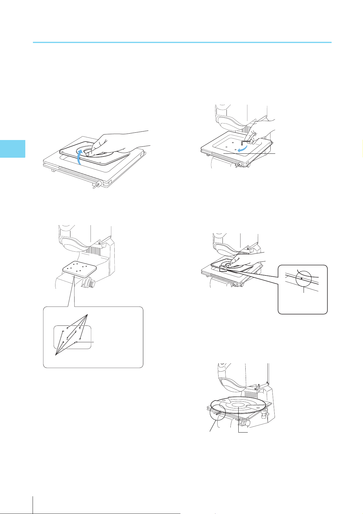
Mounting a 300 mm Wafer X-Y Stage
4
Align the
standard X-Y
stage with the
screw holes to
mount the stage.
Screw holes for the standard X-Y stage
Screw holes on electric X-Y stage
300 mm wafer X-Y
stage
Top panel protrusion
(Orient this to the
front when installing)
12 inch wafer holder
(Rotating stage)
Knob
4 Remove the top panel from the 300 mm wafer X-Y
stage.
The square panel with 4 white screws is the top panel.
Remove the top panel to leave the stage by itself.
If the 12 inch wafer holder is mounted on the 300 mm
wafer X-Y stage (rotating stage), remove it as well.
Mounting Optional Devices
5 Align the stage with the screw holes on the pedestal
to mount the 300 mm wafer X-Y stage.
6 Fix the 300 mm wafer X-Y stage to the pedestal.
Using the bolts that fixed the standard X-Y stage, fix 4
points with the provided hexagonal wrench.
7 Mounting the top panel for the 300 mm Wafer X-Y
Stage.
Orient the top panel (the rectangular panel with the four
white screws) so that the protrusion is toward the front
of the device when installing.
4-18
8 Install the 12 inch wafer holder (rotating stage).
Install the wafer holder with the knob pointed toward
the front.
VK-X100K/X200K User’s Manual
Page 69

Mounting a 300 mm Wafer X-Y Stage
4
Stage lock
When observing a 6 or 8 inch wafer, align the
wafer to the edge of the stage and fix it there.
Stage Lock
Y axis stage handle
(Front/Back movement)
Turn the stage handle to
move the stage forward
and backward.
X axis stage handle (left/right movement)
Turn the stage handle to move the stage left and
right.
Stage Lock Knob
This knob locks the
stage.
Reference
9 Mount the objective lenses and connect the cables.
“Mounting the Objective Lenses” (Page 2-3)
“Connections” (Page 2-4)
Names and Functions of the Components of the 300 mm Wafer X-Y Stage
Mounting Optional Devices
VK-X100K/X200K User’s Manual
When used in conjunction with the stand for VK
(OP-82693), fixing Z axis (locked) during mea-
surement is recommended.
4-19
Page 70

4
Mounting the Stand for VK
CAUTION
NOTICE
Important
Attaching the stand for VK (OP-82693) allows the measure-
ment unit to change height by up to 100 mm.
• Do not touch the movable portion of the Z
stage or the lower portion of the
measurement unit while either is in motion.
Doing so risks catching hands or fingers in
the mechanism.
Mounting Optional Devices
• Be sure not to drop the stand or spacers on
your feet. This may cause injury.
• Make sure that your hands and fingers are
not caught when inserting a spacer. This may
cause injury.
• Make sure that the measurement unit is firmly
attached to the stand before beginning
operation to ensure that the measurement
unit does not fall. Doing so may cause
damage to the device.
• Do not attach anything other than the
measurement unit (with a maximum weight of
12 kg) to the Z stage. Doing so may cause
damage.
• Do not turn the handles while the lock is set.
Doing so may cause damage. (The stage is
locked when it leaves the factory. Be sure to
release the stage before using the
microscope.)
Package List
Stand for VK (OP-82693) consists of the parts below.
Stand unit: 1
Effective movement range : 100 mm
Distance moved in one rotation of the handle : 30 mm
Load endurance : 12 kg
Spacer
10 mm, 20 mm, 30 mm, 40 mm of thickness: 1 each
Stainless Steel Hexagon Socket Bolts
M6 length 20 mm: 8 pieces
Hexagonal wrench M6: 1
Rotating stage: 1
4-20
When using a stand for the VK, make sure to
use the combined spacers that are provided.
Without them, the optimal performance of the
equipment may not be reached to the specs
due to the effects of such as disturbance
vibration.
VK-X100K/X200K User’s Manual
17 mm thickness
Page 71
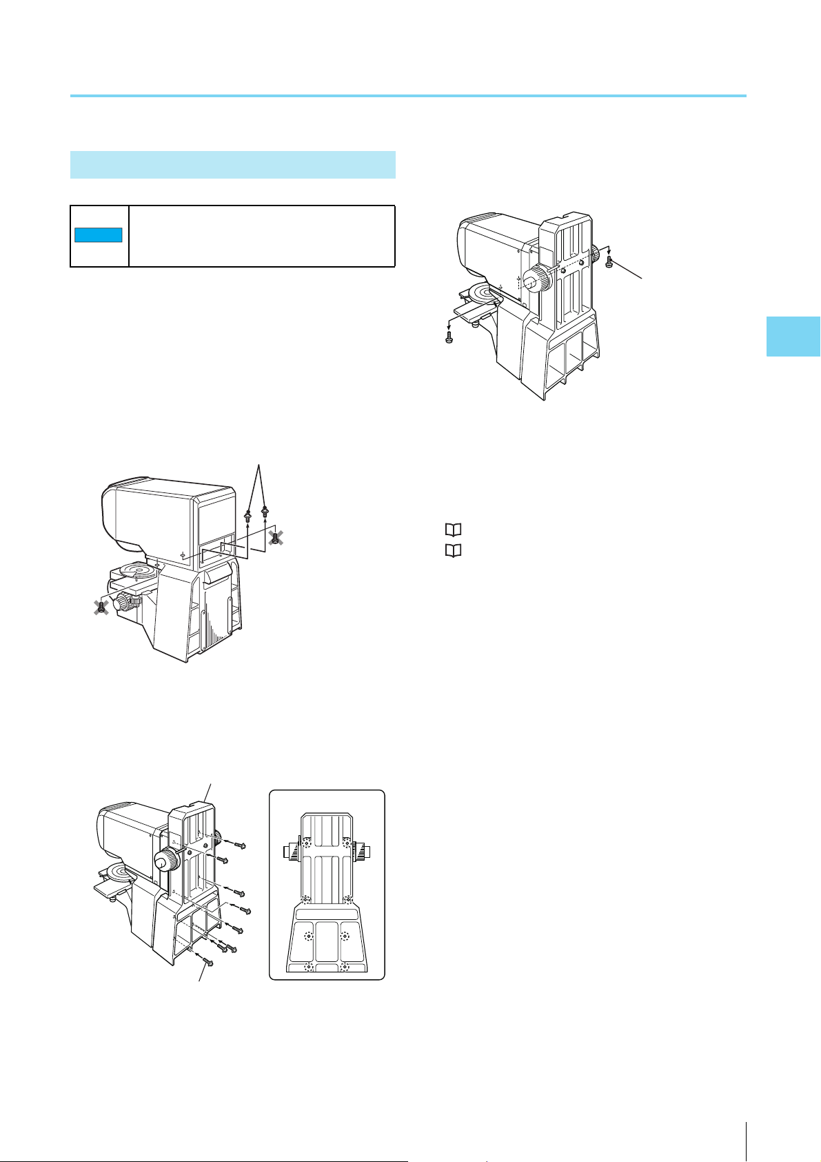
Mounting the Stand for VK
4
NOTICE
Hexagon socket bolts
Stand
Bolt fixing positions
M6 length 20 mm
Hexagon socket bolts
Mounting the Stand for VK
Remove the objective lenses before installing
or removing the stand. Doing so may cause
damage.
1 Confirm all of the objective lenses and cables are
removed.
2 Remove the hexagonal fixing bolts from the back of
the microscope unit (measurement unit).
Do not remove the hexagon socket bolts from the front
of the device.
4 Remove the 2 hexagonal fixing bolts from the front
of the microscope unit (measurement unit).
Mounting Optional Devices
5 Place the provided rotating stage (17 mm thickness)
on the X-Y stage.
6 Mount the objective lenses and connect the cables.
“Mounting the Objective Lenses” (Page 2-3)
“Connections” (Page 2-4)
3 Attach the VK stand to the microscope unit.
Fix the stand for VK to the measurement unit and the
pedestal with 20 mm long M6 bolts (at 8 points).
VK-X100K/X200K User’s Manual
4-21
Page 72

Mounting the Stand for VK
4
Z stage handle
lock
Slide handle
Z stage
Z stage Handle
lock
Slide handle
Lock
Spacer
Spacer
Z stage
handle lock
How to Use the Stand for VK
Names of each part
Mounting Optional Devices
Using the stage
3 After fixing the measurement unit with Z stage han-
dle lock so that it does not move, insert spacers
between the measurement unit and the pedestal.
Insert the spacer that is the closest in thickness in the
gap between the measurement unit and the pedestal.
Multiple spacers can be combined for insertion.
4 Unlock the Z stage handle lock, to lower the mea-
surement unit onto the spacer slowly.
1 Unlocks the Z stage handle lock.
2 Turn the slide handle to adjust the height of the
measurement unit so that it meets the height of the
sample.
5 Lock the Z stage handle once again.
After this, perform normal adjustment and measure-
ment.
Locking the lock mechanism should be
NOTICE
done after inserting the spacer. Locking
without inserting the spacer may cause
failure.
4-22
VK-X100K/X200K User’s Manual
Page 73

Chapter
5
5
Maintenance
This chapter describes the procedure for replac-
ing the lamp and the fuse in the control unit.
Replacing the Lamp in the Control Unit .................Page 5-2
Replacing the Fuse ................................................Page 5-4
Maintenance
VK-X100K/X200K User’s Manual
5-1
Page 74

5
Replacing the Lamp in the Control Unit
CAUTION
NOTICE
Point
Control Unit
Lamp Cover
Bolt
Lamp
Lock Lever
Lamp Holder
Lamp
Socket
Lamp
The average life of the lamp is about 1000 hours of illumina-
tion (when used at room temperature).
This section explains how to change the lamp.
Turn the main power off on the control unit and
wait for thirty minutes or more before
replacing the lamp. The lamp is extremely hot
and may cause burns.
Use a JCR12V100W10H (OP-91641) or the
equivalent as a replacement lamp. Doing so
may cause damage.
3 Bring down the lock lever to the right.
The lamp in the lamp holder comes out toward you by
approx. 1/3.
Maintenance
Have a Phillips head screwdriver ready to
remove/install the bolts.
1 Shut down the system and turn the main power of
the control unit off.
“Shutting Down the System” (Page 3-4)
2 Pull out the bolt on the lamp cover out of the control
unit, removing it by pulling the lamp cover to the
left.
4 Pull the lamp out toward you.
The lamp holder holds the lamp from above and below.
Do not use excessive force to remove the
NOTICE
lamp. Doing so may result in damage to the
socket cable.
5-2
5 Remove the lamp from the socket and replace it with
a new lamp.
VK-X100K/X200K User’s Manual
Page 75

5
6 Insert the lamp into the lamp holder.
Notch
Lamp
Lamp Holder
Protrusion
Lamp
Lock Lever
Bolt
7 Return the lock lever to the original position.
Replacing the Lamp in the Control Unit
Maintenance
The lamp will be fixed to the lamp holder.
8 Attach the lamp cover, fixing with bolts.
VK-X100K/X200K User’s Manual
5-3
Page 76
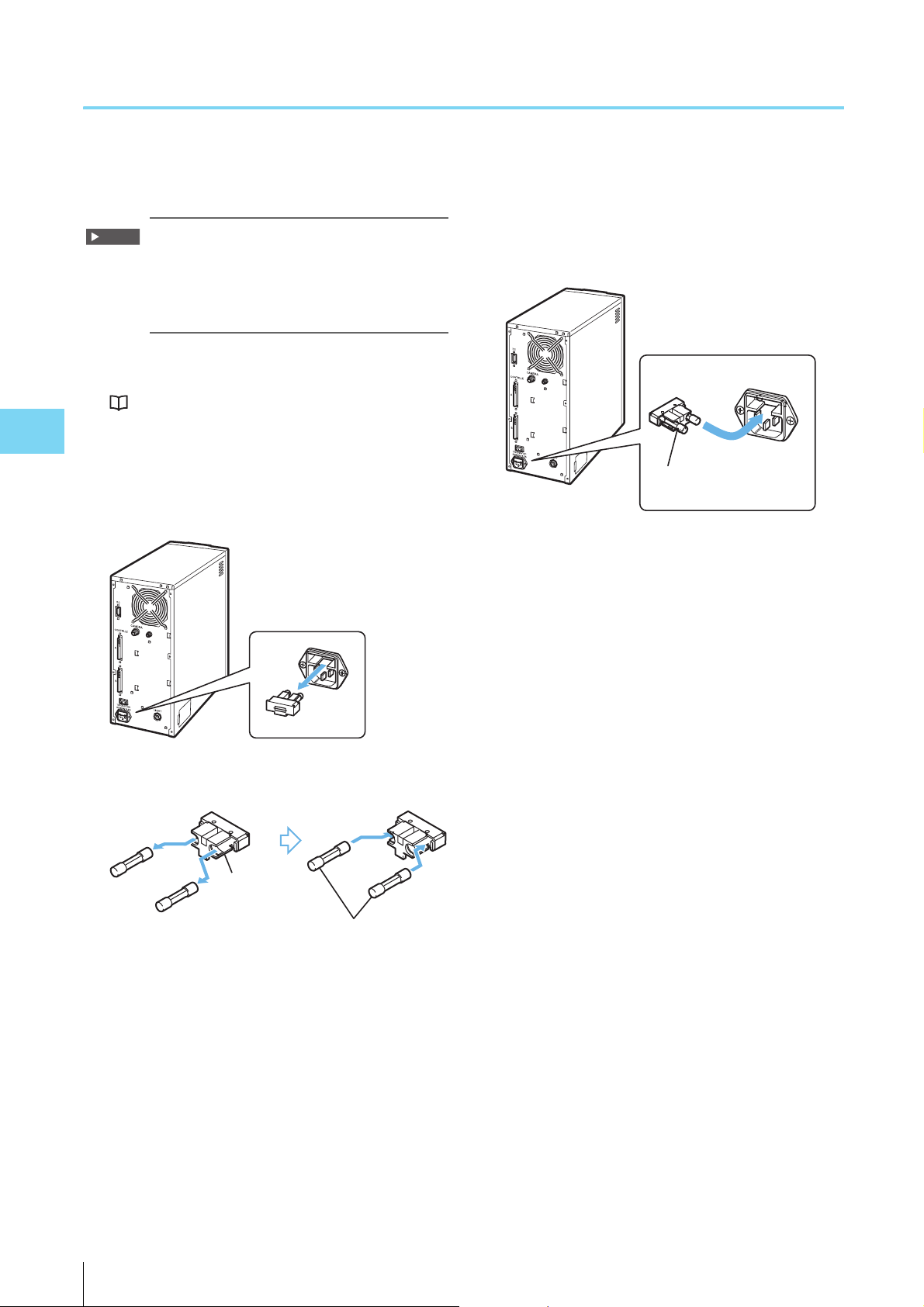
5
Replacing the Fuse
Important
Fuse Holder
Fuse Holder
New fuse
Electrode
Insert straight
Insert with the protrusion
facing down
This section explains how to change the fuse in the control
unit.
Use the product below as a replacement fuse.
SOC-made HT Series
Rated voltage : 250 V
Rated current : 6.3 A
Blowout Characteristic : Time lag
1 Shut down the system and turn the main power of
the control unit off.
“Shutting Down the System” (Page 3-4)
Maintenance
2 Remove the power cable.
3 Pull out the fuse holder from the power connector.
5 Return the fuse holder back to the power connector.
With the protrusion of the fuse holder facing down,
insert it straight so that the fuse comes in contact with
the electrode of the fuse holder.
4 Install a new fuse in the fuse holder.
5-4
VK-X100K/X200K User’s Manual
Page 77

A
Appendix
This chapter describes the specifications and di-
mensions of the VK-X100K/X200K Series.
Specifications ....................................................... Page A-2
Dimensions .......................................................... Page A-4
Appendix
VK-X100K/X200K User’s Manual
A-1
Page 78

A
Specifications
Model Control unit (VK-X100K) Control unit (VK-X200K)
Microscope unit (VK-X105) Microscope unit (VK-X110) Microscope unit (VK-X210)
Monitor magnification 100 200 400 1000 200 400 1000 2000 200 400 1000 3000
Objective lens magnification 5x 10x 20x 50x 10x 20x 50x 100x 10x 20x 50x 150x
Observation
measurement
1
range*
Operating distance: (mm) 22.5 16.5 3.1 0.54 16.5 3.1 0.54 0.3 16.5 3.1 0.35 0.2
Numerical aperture (N.A.) 0.13 0.3 0.46 0.8 0.3 0.46 0.8 0.95 0.3 0.46 0.95 0.95
Measurement optics Pinhole confocal optics
Height
measurement
Width
measurement
Frame memory Images (monochrome) 16 bits
Appendix
Measurement
quality
Frame rate (Hz) Superfine 4 Hz
Optical zoom 1 to 8x
Auto function Setting the Auto-gain/Auto-focus/Auto-selection of up/down limits/Double-scan brightness
Measurement
laser light
source
Photoreceptor PMT (Photomultiplier)
Optical
observation
light source
Optical
observation
Color camera
H (horizontal): μm 2700 1350 675 270 1350 675 270 135 1350 675 270 90
V (vertical): μm 2025 1012 506 202 1012 506 202 101 1012 506 202 67
Measurement Range 7 mm
Display resolution 0.005 μm 0.0005 μm
Repeatability σ 0.02 μm*
Display resolution 0.01 μm 0.001 μm
Repeatability 3σ 0.05 μm*
Images (color) RGB 8 bits each
Height measurement 21 bits 24 bits
Superfine 2048 × 1536
Standard/High speed 1024 × 768
Part 1/12 1024 × 64
Standard/High speed 9 Hz
High speed (skip) 15 Hz
High speed (skip
double)
Part 1/12 70 Hz, skip double 120 Hz
Line peak/Line film
thickness
Wavelength Red laser
Output 0.95 mW
Pulse width 1 ns —
Class Class 2 Laser Product (IEC60825-1, FDA(CDRH) Part1040.10*
Lamp 100 W halogen
Service life 1000 hours (average)
Color temperature 3100 K
Image pickup device 1/3 color CCD image sensor
Resolution 800000 pixels
21.6 million pixels: 800K pixels × pixel shift (3 × 3) mode × 3 CCD mode
Adjustment Gain, Shutter speed
White balance AUTO/MANUAL/PUSHSET
3
2.4 million pixels: 800K pixels × 3 CCD mode
3.2 million pixels: 800K pixels × pixel shift(2 × 2) mode
7.2 million pixels: 800K pixels × pixel shift (3 × 3) mode
2
0.03 μm*
7800 Hz (when Z pitch is 0.1 μm or less)
658 nm
4
25 Hz
0.012 μm*
0.02 μm*
Violet laser
408 nm
6
2
5
)
A-2
VK-X100K/X200K User’s Manual
Page 79

Specifications
A
Model Control unit (VK-X100K) Control unit (VK-X200K)
Microscope unit (VK-X105) Microscope unit (VK-X110) Microscope unit (VK-X210)
Maximum
sample size
Z stage Stroke 28 mm
X-Y stage Stroke 70 × 70 mm
Rotating stage Rotation angle 360 degrees
Data processing unit Dedicated PC specified by KEYENCE (OS: Windows 7 Professional) *
Power Power voltage 100 to 240 VAC, 50/60 Hz
Environmental
resistance
Weight Microscope unit
Maximum sample
height
Maximum sample size Diameter of 318 mm to observe the entire object at once
Maximum load 5 kg
Current consumption Up to 450 VA
Ambient temperature +15 to +28°C
Ambient humidity 35 to 65% RH
Floor vibration at the
installation place
(Measurement unit and
pedestal)
Control unit Approx. 11 kg
-3
1.5×10
m/s2 or less (For frequencies less than 5 Hz, the amplitude should be less than 3 μm)
Approx. 25 kg
(Measurement unit alone when separated: Approx 8.5 kg)
28 mm*
7
8
Approx. 26 kg
(Measurement unit alone when
separated: Approx. 10 kg)
Appendix
*1 The observation measurement range is set as the minimum field of vision.
*2 When using the 50x objective lens to measure the standard step of 2 μm
*3 When using the 50x objective lens (2x optical zoom) to measure the line peak (8x image averaging) of a 1 μm wide
line from the KEYENCE Standard Chart
*4 When using the 100x objective lens to measure the line peak (8x image averaging) of a 1 μm wide line from the KEY-
ENCE Standard Chart
*5 When using the 150x objective lens to measure the line peak (8x image averaging) of a 1 μm wide line from the KEY-
ENCE Standard Chart
*6 The laser classification for FDA(CDRH) is implemented based on IEC60825-1 in accordance with the requirements of
Laser Notice No.50
*7 This can be increased by up to 128 mm using the optional spacer and the stand.
*8 Windows 7 is the registered trademark of U.S. Microsoft Corp.
VK-X100K/X200K User’s Manual
A-3
Page 80
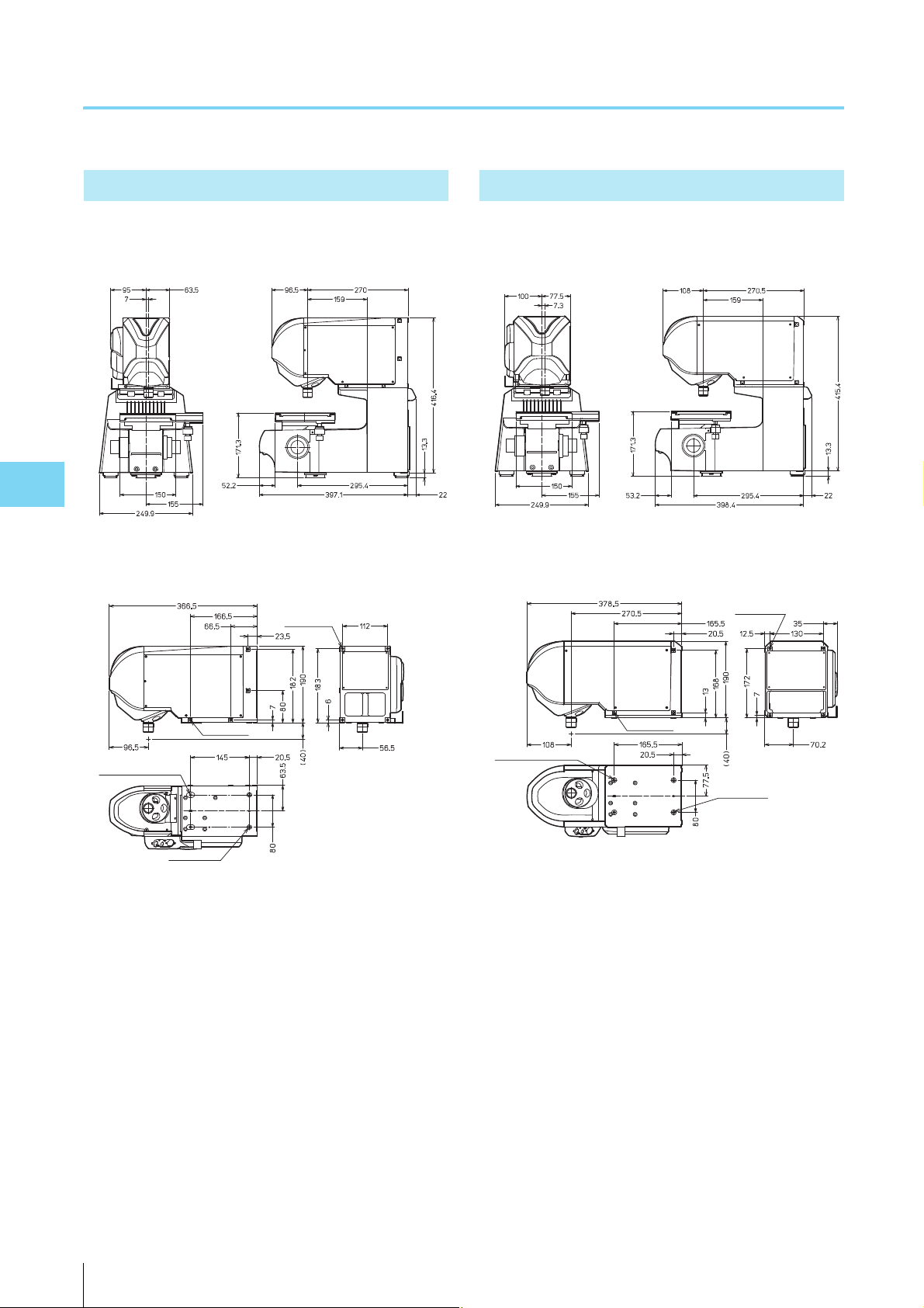
A
Dimensions
Unit: mm
Unit: mm
4×M6 Depth 10
2×M6 Depth 8 coil 1.5 D
2×φ6.6 piercing
3xM6 Depth 8
Unit: mm
4×M6 Depth 10
2×M6 Depth 8 coil 1.5 D
2×φ6.6 piercing
3xM6 Depth 8
Unit: mm
VK-X105/X110
Microscope unit
Appendix
Measurement unit
VK-X210
Microscope unit
Measurement unit
A-4
VK-X100K/X200K User’s Manual
Page 81

A
VK-X100K/X200K (Control Unit)
Unit: mm
Dimensions
Appendix
VK-X100K/X200K User’s Manual
A-5
Page 82

A
Index
Numerics
300 mm wafer X-Y stage ................................................4-2
A
A variety of the standard objective lens and how to select
one .................................................................................3-5
ACCESS lamp .............................................................. 1-14
Adjusting brightness ....................................................3-11
Adjusting the focus ...................................................... 3-10
Adjusting the observation position ..............................3-10
Adjusting the positions of the laser and the camera ..... 3-7
Adjustment of the observation position/magnification ... 3-9
APERTURE SHUTTER (aperture iris shutter) ............... 1-12
Appendix
C
Camera cable .........................................................1-9, 2-4
CAMERA connector ............................................1-12, 1-14
Confocal laser optics ..................................................... 1-2
Connecting the control unit to the control PC ................ 2-7
Connecting the microscope unit and control unit .......... 2-6
Connection diagram ......................................................2-4
Connection procedure ................................................... 2-6
Control PC ...............................................................1-6, 2-5
Control unit ...................................................... 1-6, 1-9, A-5
Controller A cable ...................................................1-9, 2-4
CONTROLLER A connector ................................1-12, 1-14
Controller B cable ...................................................1-9, 2-4
CONTROLLER B connector ................................1-12, 1-14
Cord hook .................................................................... 1-12
Correction in the film thickness measurement ............... 3-6
H
How to use the stand for VK ........................................ 4-22
I
Initializing lens position .................................................. 3-8
Installation environment ............................................... 1-11
L
Laser radiation emission warning .......................1-13, 1-14
LASER SHUTTER (beam stop) .................................... 1-12
LIGHT connector ................................................1-12, 1-14
Loading the sample ....................................................... 3-9
M
Measurement unit ........................................... 1-6, 2-4, A-4
Microscope unit ....................................................1-10, A-4
Microscope unit (left/front view) .................................. 1-12
Microscope unit (right/front view) ................................ 1-13
Mounting a 300 mm wafer X-Y stage .......................... 4-17
Mounting the measurement unit .................................... 4-6
Mounting the objective lenses ....................................... 2-3
Mounting the spacer for the VK-X105/X110 ................ 4-12
Mounting the spacer for the VK-X210 ........................... 4-7
Mounting the stand for VK ...........................................4-20
N
Names and functions of each part of the 300 mm Wafer X-
Y stage ......................................................................... 4-19
O
D
Dimensions ....................................................................A-4
Display ........................................................................... 1-6
E
Electrical signal processing ........................................... 1-4
F
Fiber optic cable .....................................................1-9, 2-4
Focusing handle (coarse) ...................................1-12, 1-13
Focusing handle (fine) ........................................1-12, 1-13
Focusing handle lock ................................................... 1-13
A-6
VK-X100K/X200K User’s Manual
Objective lens .............................................................. 1-13
Optics ............................................................................ 1-4
Option .....................................................................1-5, 4-2
Output data creation ...................................................... 1-4
P
Pedestal .........................................................1-10, 4-4, 4-6
Principle .........................................................................1-2
R
Removing the measurement unit ................................... 4-4
Replacing the fuse ......................................................... 5-4
Replacing the lamp .......................................................5-2
Page 83

A
Revolver .......................................................................1-13
Rotating stage ..............................................................1-12
S
SCAN CONTROL cable ..........................................1-9, 2-4
SCAN CONTROL connector ...............................1-12, 1-14
Selecting magnification .................................................3-9
Shutting down the system .............................................. 3-4
Spacer ...........................................................................4-2
Spacer (OP-38162) ......................................................4-12
Spacer (OP-51426) ........................................................4-7
Specifications ............................................................... A-2
Stand ..............................................................................4-2
Standard chart ...............................................................1-9
Standard objective lenses ...........................................1-10
Starting up the system ...................................................3-3
System configuration .....................................................1-5
Index
Appendix
U
Unlocking the X-Y stage lock .........................................2-2
USB cable ...............................................................1-9, 2-4
X
X axis stage handle .....................................................1-13
X axis stage lock ..........................................................1-12
X-Y stage .....................................................................1-13
Y
Y axis stage handle .....................................................1-13
Y axis stage lock ..........................................................1-12
VK-X100K/X200K User’s Manual
A-7
Page 84

Print date Revision no. Description
June 2011
November 2011
April 2012
July 2013
Initial release
2nd edition
3rd edition
4th edition
Revision History
Page 85

WARRANTIES AND DISCLAIMERS
(1) KEYENCE warrants the Products to be free of defects in materials and workmanship for a period of one (1) year from
the date of shipment. If any models or samples were shown to Buyer, such models or samples were used merely to
illustrate the general type and quality of the Products and not to represent that the Products would necessarily
conform to said models or samples. Any Products found to be defective must be shipped to KEYENCE with all
shipping costs paid by Buyer or offered to KEYENCE for inspection and examination. Upon examination by
KEYENCE, KEYENCE, at its sole option, will refund the purchase price of, or repair or replace at no charge any
Products found to be defective. This warranty does not apply to any defects resulting from any action of Buyer,
including but not limited to improper installation, improper interfacing, improper repair, unauthorized modification,
misapplication and mishandling, such as exposure to excessive current, heat, coldness, moisture, vibration or
outdoors air. Components which wear are not warranted.
(2) KEYENCE is pleased to offer suggestions on the use of its various Products. They are only suggestions, and it is
Buyer's responsibility to ascertain the fitness of the Products for Buyer’s intended use. KEYENCE will not be
responsible for any damages that may result from the use of the Products.
(3) The Products and any samples ("Products/Samples") supplied to Buyer are not to be used internally in humans, for
human transportation, as safety devices or fail-safe systems, unless their written specifications state otherwise.
Should any Products/Samples be used in such a manner or misused in any way, KEYENCE assumes no
responsibility, and additionally Buyer will indemnify KEYENCE and hold KEYENCE harmless from any liability or
damage whatsoever arising out of any misuse of the Products/Samples.
(4) OTHER THAN AS STATED HEREIN, THE PRODUCTS/SAMPLES ARE PROVIDED WITH NO OTHER
WARRANTIES WHATSOEVER. ALL EXPRESS, IMPLIED, AND STATUTORY WARRANTIES, INCLUDING,
WITHOUT LIMITATION, THE WARRANTIES OF MERCHANTABILITY, FITNESS FOR A PARTICULAR PURPOSE,
AND NON-INFRINGEMENT OF PROPRIETARY RIGHTS, ARE EXPRESSLY DISCLAIMED. IN NO EVENT SHALL
KEYENCE AND ITS AFFILIATED ENTITIES BE LIABLE TO ANY PERSON OR ENTITY FOR ANY DIRECT,
INDIRECT, INCIDENTAL, PUNITIVE, SPECIAL OR CONSEQUENTIAL DAMAGES (INCLUDING, WITHOUT
LIMITATION, ANY DAMAGES RESULTING FROM LOSS OF USE, BUSINESS INTERRUPTION, LOSS OF
INFORMATION, LOSS OR INACCURACY OF DATA, LOSS OF PROFITS, LOSS OF SAVINGS, THE COST OF
PROCUREMENT OF SUBSTITUTED GOODS, SERVICES OR TECHNOLOGIES, OR FOR ANY MATTER ARISING
OUT OF OR IN CONNECTION WITH THE USE OR INABILITY TO USE THE PRODUCTS, EVEN IF KEYENCE OR
ONE OF ITS AFFILIATED ENTITIES WAS ADVISED OF A POSSIBLE THIRD PARTY’S CLAIM FOR DAMAGES
OR ANY OTHER CLAIM AGAINST BUYER. In some jurisdictions, some of the foregoing warranty disclaimers or
damage limitations may not apply.
BUYER'S TRANSFER OBLIGATIONS:
If the Products/Samples purchased by Buyer are to be resold or delivered to a third party, Buyer must provide such
third party with a copy of this document, all specifications, manuals, catalogs, leaflets and written information provided
to Buyer pertaining to the Products/Samples.
E 1101-3
Page 86

A4WW1-MAN-1101
Copyright (c) 2012 KEYENCE CORPORATION. All rights reserved. 11565E 1073-4 96M11880 Printed in Japan
Specifications are subject to change without notice.
KEYENCE CORPORATION
1-3-14, Higashi-Nakajima, Higashi-Yodogawa-ku, Osaka, 533-8555, Japan PHONE: +81-6-6379-2211
AUSTRIA
Phone: +43 22 36-3782 66-0
BELGIUM
Phone: +32 1 528 1222
BRAZIL
Phone: +55-11-3045-4011
CANADA
Phone: +1-905-366-7655
CHINA
Phone: +86-21-68757500
CZECH REPUBLIC
Phone: +420 222 191 483
FRANCE
Phone: +33 1 56 37 78 00
GERMANY
Phone: +49 6102 36 89-0
HONG KONG
Phone: +852-3104-1010
HUNGARY
Phone: +36 1 802 73 60
INDIA
Phone: +91-44-4299-4192
ITALY
Phone: +39-02-6688220
KOREA
Phone: +82-31-789-4300
MALAYSIA
Phone: +60-3-2092-2211
MEXICO
Phone: +52-81-8220-7900
NETHERLANDS
Phone: +31 40 20 66 100
POLAND
Phone: +48 71 36861 60
ROMANIA
Phone: +40 269-232-808
SINGAPORE
Phone: +65-6392-1011
SLOVAKIA
Phone: +421 2 5939 6461
SLOVENIA
Phone: +386 1-4701-666
SWITZERLAND
Phone: +41 43-45577 30
TAIWAN
Phone: +886-2-2718-8700
THAILAND
Phone: +66-2-369-2777
UK & IRELAND
Phone: +44-1908-696900
USA
Phone: +1-201-930-0100
 Loading...