

Page 1
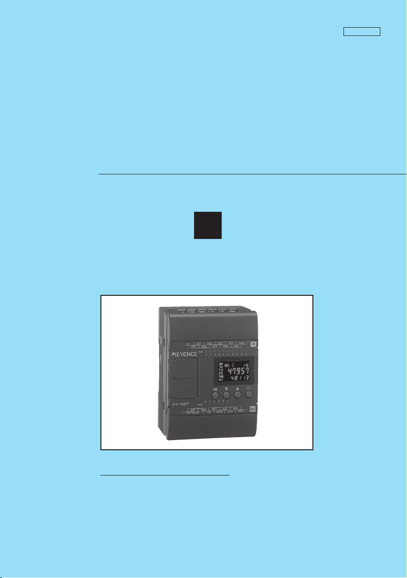
User’s Manual
Visual KV Series
3
Programming
96M0366
How this manual is organized:
The Visual KV Series User’s Manual is composed of 3 separate
manuals; 1-Installation, 2-Support Software, 3-Programming.
Please read each manual relevant to your purpose.
Page 2
Safety Precautions
This instruction manual describes the operation and function of the KV Series PLC.
Read this manual carefully to ensure safe use and maximum performance from your
KV Series PLC.
Symbols
The following symbols alert you to important messages. Be sure to read these
messages carefully.
WARNING
Failure to follow instructions may lead to injury. (electric
shock, burn, etc.)
Note:
Conventions
This manual describes the operation/function of all Keyence KV Series PLC.
Note following conventions when you use.
Visual KV (Series) KV-10AR/AT/DR/DT KV-16AR/AT/DR/DT
KV-10xx, 16xx, 24xx, 40xx KV-24AR/AT/DR/DT KV-40AR/AT/DR/DT
Conventional KV (Series) KV-10R(W)/T(W) KV-16R(W)/T(W)
KV-300 (Series) KV-24R(W)/T(W) KV-40R(W)/T(W)
KV-10/80 (Series) KV-80R(W)/T(W)
General Precautions
• At startup and during operation, be sure to monitor the functions and performance of the KV Sereis PLC.
• We recommend that you take substantial safety measures to avoid any damage
in the event a problem occurs.
• Do not open or modify the KV Series PLC or use it in any way other than described in the specifications.
• When the KV Series PLC is used in combination with other instruments, functions and performance may be degraded, depending on operating conditions and
the surrounding environment.
• Do not use the KV Series PLC for the purpose of protecting the human body.
CAUTION
Failure to follow instructions may lead to product damage.
Provides additional information on proper operation.
KV-300
(1)
Note: The built-in display may show the error message "Error 40" blinking the very
first time you turn on the power supply to the Visual KV Series. Press any key
around the display to cancel this message.
The Visual KV Series shows this message when no program is loaded.
Page 3

Note to User
When using the Visual KV Series in the following conditions or environments, be
sure to use the Visual KV Series with sufficient margin regarding the rating and
functions, take appropriate safety precautions such as fail-safe, and contact our
sales personnel if any questions arise.
• Use in conditions or environments not described in this manual
• Use for nuclear power control, railway facilities, air service facilities, vehicles,
combustion devices, medical equipment, amusement machines, safety equipment, etc.
• Use for applications where large effects are predicted to be given on human lives
and properties and safety is especially requested.
Restriction on Acquiring the CE Marking
■ Restriction to be compatible with EMC directives
• When using a relay output type unit (whose model name ends with "R"), connect
spark killers having the appropriate withstand voltage against the load to the
output terminals in parallel to contacts (because the unit discharges when a relay
contact becomes open and noise is generated). In our experiments, we use the
following models of spark killers.
XEB0101 0.1 µF-10 Ω manufactured by OKAYA DENKI SANGYO
The following 1-turn ferrite core is added to the AC power input circuit of the KV40AR/T, the KV-24AR/T and to the DC power input circuit of the KV-40DR/T.
ZCAT3035-1330 manufactured by TDK
Note: The contents above do not by themselves ensure that the entire machine
manufactured in accordance with the above contents is compatible with EMC
directives.
You must judge by yourself whether or not the entire machine is compatible with
EMC directives because compatibility may change depending on the component
configuration, wiring and location inside of the machine.
■ Restriction on compatibility with low-voltage directives (IEC-1010-1)
• Use insulated type crimp-style terminals.
• For wiring materials, use lead wires whose sheath is 0.4 mm or more.
• The Visual KV Series is allowed to be installed in a vertical position only.
(Spacers for expansion units are not available.)
• Be sure to use the Visual KV Series inside the control panel.
96M0366
(2)
Page 4

Features of the Visual KV Series
● Extremely small
The Visual KV Series is the smallest in the world among AC type PLCs equipped
with screw terminal blocks, and saves installation space.
● Extremely fast
The minimum scan time is 140 µs and minimum instruction execution time is 0.7
µs, which is the fastest control in its class.
● AC power built-in type newly added
AC power built-in type units are newly added. This type can be used in small
spaces where a switching power supply unit cannot be installed.
● Excellent Access Window
An Access Window with two-color backlight is adopted in all models to facilitate
changing and monitoring of device data. Changing between RUN mode and
PROGRAM mode, checking the error code when an error has occurred, etc. can
be performed in a Visual KV Series unit without the need for any handheld
programmer.
The analog trimmer, which has been popular in the conventional KV Series, is
digitized to enable more detail settings. [Digital trimmers]
● User message setting function
In the Access Window, 256 different user messages can be displayed. This
function can be used to give instructions on works on the production line, indicate
abnormalities in the units, etc.
● Program write in RUN mode
Ladder programs can be changed even while the system is running.
● Equipped with two serial ports
Visual KV Series basic units are equipped with two serial ports to connect peripheral units, improving the debug environment.
(The KV-10xx is equipped with only one serial port.)
● Easy Ramp-up/down control function
The one-axis motor control function is offered separately from high-speed
counters so that feedback control is enabled.
● Equipped with two 24-bit high-speed 30 kHz, two-phase counters
The Visual KV Series is equipped with two high-speed counters each with a twopoint comparator output function that enables high-speed encoder input.
● Specified frequency pulse output function
High-speed counters can function as pulse oscillators of 50 kHz maximum with
easy setting, without creating a complicated ladder program.
● Frequency counter function
High-speed counters can function as frequency counters with easy setting,
without creating complicated ladder programs.
● Cam switch function
High-speed counters can function as cam switches with easy setting, without
creating complicated ladder programs.
(3)
Page 5

● Interrupt function
The Visual KV Series is equipped with four high-speed interrupt inputs of
10 µs maximum.
● Input time constant change function
The time constant can be set in 7 steps from 10 µs to 10 ms.
● Double memory backup functions
In addition to a conventional SRAM battery backup function, the Visual KV Series
is also equipped with an EEPROM backup function.
Compatibility with Conventional KV Series Peripheral Units
The Visual KV Series functions as a high-end compatible model of the conventional
KV Series. Peripheral units of the conventional KV Series such as the ladder support
software "KV IncrediWare (DOS)" and "LADDER BUILDER for KV" and the
handheld programmer KV-P3E(01) can be used since they are part of the Visual KV
Series.
However, it should be noted that the contents have changed as follows.
• The internal clock cycle of high-speed counters consists of three types: 1 µs, 10
µs, and 100 µs.
• The time constant for an input relay specified by the HSP instruction is 10 µs.
• The analog trimmer function is set with the Access Window built into the basic
unit.
• The available device setting range of the TMIN instruction is from 0 to 65535.
[Handheld programmer KV-P3E(01) can display 0 to 9999 .]
• The RUN/PROGRAM LED is displayed in the Access Window provided on the
front face of the basic unit.
• Transistor output is not independent, but is common.
• With the transistor type, the output terminal layout is different.
• The specifications for output current of transistor outputs Nos. 500 to 502 is 100
mA.
• Conventional KV Series expansion units are not available as expansion units for
the Visual KV Series.
• The channel setting switch is not provided for expansion units. Channels are
determined in connection order.
• Scans in expansion I/O units are not synchronous with the scan time in Visual KV
Series basic units.
• Assignment of special utility relays has partially changed.
• Data memory device Nos. DM1000 to DM1999 are assigned as special data
memories.
(4)
Page 6

Cautions when using the previous version of ladder support software
Pay strict attention to the following items when using the ladder support software.
• When using the ladder support software "KV IncrediWare (DOS)" or "LADDER
BUILDER for KV Ver. 1.0x", set the model to "KV-300".
• DM0 to DM1999 are only available.
CAUTION
When the ladder support software "LADDER BUILDER for KV Ver. 1.0x" is
used, do not use the monitor’s Change All function. If the Change All function
is used, the basic unit may be damaged. Never use the Change All function.
Peripheral units and other units incompatible with the Visual KV Series
Peripheral units in the conventional KV Series and other units shown below are not
compatible with the Visual KV Series.
• Expansion I/O units for the conventional KV Series: KV-8ER/8ET/8EX/16EX/
8EYR/8EYT/16EYR/16EYT
• Analog I/O units for the conventional KV Series: KV-AD4/DA4
Cautions when Using the Serial Port
The KV-16xx/24xx/40xx units are equipped with two RJ-11 modular connectors for
serial communication.
When using them, pay strict attention to the following contents:
• Programs can be transferred and monitored using either communication port A or
B. However, never connect the ladder software and a handheld programmer to
the two ports at the same time.
• The KV-D20 operator interface panel can be connected to either communication
port A or B. However, only one KV-D20 unit can be connected to a single basic
unit.
• Never leave both the KV-D20 operator interface panel and KV-P3E(01) handheld
programmer on simultaneously for a long period of time.
(5)
Page 7

(6)
Page 8

How this manual is organized
The Visual KV Series User’s Manual is composed of 3 separate manuals;
1-Installation, 2-Support Software, 3-Programming. Please read each manual
relevant to your purpose.
1
Installation
Chapter 1 Configuration and Specifications [Visual KV Series Only]
Describes the system configuration of the Visual KV Series, the names and functions of
each part, and the specifications.
Chapter 2 System Installation [Visual KV Series Only]
Describes the installation and connection of each Visual KV Series unit as well as
system maintenance.
Chapter 3 Access Window [Visual KV Series Only]
Describes the Access Window used for changing and monitoring data.
Chapter 4 KV-D20 Operator Interface Panel [Visual KV Series Only]
Describes the KV-D20 Operator Interface Panel used for changing, monitoring, and
displaying the status of inside relays, timers, counters and data memories.
Chapter 5 KV-300, KV-10/80 Hardware [KV-300, KV-10/80 Series Only]
Describes the hardware specifications and wirings for KV-300 and KV-10/80 Series.
Chapter 6 Handheld Programmer
Describes how to use the handheld programmer and memory card.
Chapter 7 KV-L2 Serial Interface Module [KV-300 Series Only]
Describes the serial interface modules for KV-300 Series.
Chapter 8 KV-AN6 Analog I/O Module [KV-300 Series Only]
Describes the optional Analog I/O module for KV-300 Series
Chapter 9 KV-AD4/DA4 Analog I/O Unit [KV-10/80 Series Only]
Describes the optional Analog I/O unit for KV-10/80 Series.
Chapter 10 Troubleshooting
This chapter describes the error code list, countermeasures against problems, and error
indications for each unit.
Appendices
The appendix includes a list of ladder program applications and the index.
2Support Software
Chapter 1 Introduction
Describes the items included in the package, the product outline, the method to connect
a personal computer, the installation method, etc.
(7)
Page 9

Chapter 2 Editor
Describes the operating procedures in Editor mode.
Chapter 3 Simulator
Describes the operating procedures in Simulator mode.
Chapter 4 Monitor
Describes the operating procedures in Monitor mode.
Appendices
Includes instructions list, devices list, sample program list and quick reference for key
operation and shortcuts.
3Programming
Chapter 1 Programming
Describes basic knowledge including program creation procedures, device configuration,
relay assignments, special functions to set and confirm Visual KV Series operations, as
well as the extended ladder diagrams. Understand the contents described here completely at first before creating programs.
Chapter 2 Instructions
Describes the concrete usage of instructions in the KV Series.
Refer to "Chapter 3 Interrupts" on page 3-183 for details of interrupt instructions.
Refer to "Chapter 4 High-speed counters" on page 3-195 for details of the high-speed
counters used in the application instruction.
Chapter 3 Interrupts [Visual KV Series Only]
The interrupt processing function executes an interrupt program when an external input
or request from the high-speed counter comparator (interrupt factor) is encountered
during KV operation.
This chapter describes the types of interrupt factors as well as inputs and outputs
encountered during interrupt processing.
Chapter 4 High-speed Counters [Visual KV Series Only]
Describes high-speed counters and high-speed counter comparators, which allow highspeed pulse measurement and pulse output, independent of the scan time.
Chapter 5 Positioning Control [Visual KV Series Only]
Describes ramp-up/down control of stepping motors and servo motors.
Chapter 6
Interrupts, High-speed Counters, Positioning Control [KV-300, KV-10/80 Series Only]
Describes ramp-up/down control of stepping motors and servo motors.
Chapter 7 Serial Communication
The KV Series can be connected to an external device with an RS-232C interface to
establish communication.
This chapter describes communications specifications, how to connect the KV Series to
external devices, and how to perform communication.
Chapter 8 Programming Examples
Describes the typical programming examples for KV-10/80 Series. These programs can
be used for Visual KV Series. However, pay attention to the I/O addressing compatibility
before use.
(8)
Page 10

Contents
3Programming
Chapter 1 Programming
1.1 Before Creating Programs ..............................................................................3-2
1.1.1 Flow from Introduction to Operation ................................................................... 3-2
1.1.2 Scan Time ...........................................................................................................3-3
1.2 User Memory ....................................................................................................3-4
1.2.1 Program Capacity ...............................................................................................3-4
1.3 Device Configuration .......................................................................................3-5
1.3.1 Device List .......................................................................................................... 3-5
1.3.2 Relay No. ............................................................................................................3-7
1.3.3 Assigning Relay Nos. ..........................................................................................3-8
1.3.4 Input Relays ........................................................................................................3-9
1.3.5 Output Relays ...................................................................................................3-10
1.3.6 Internal Utility Relays ........................................................................................3-11
1.3.7 Special Utility Relays ........................................................................................ 3-12
1.3.8 Special Utility Relay List ................................................................................... 3-14
1.3.9 Timers and Counters ........................................................................................ 3-18
1.3.10 Data Memories ................................................................................................. 3-19
1.3.11 Temporary Data Memory ..................................................................................3-21
1.3.12 Relay Nos. and Functions .................................................................................3-22
1.4 Special Functions ..........................................................................................3-23
1.4.1 Input Time Constant Change Function .............................................................3-23
1.4.2 Modifying the Input Relay Time Constant .........................................................3-24
1.4.3 Constant Scan Time Mode ............................................................................... 3-25
1.4.4 Output Disabled Function ................................................................................. 3-26
1.4.5 Input Refresh Disabled Function ...................................................................... 3-26
1.4.6 Contact Comment Save Function .....................................................................3-27
1.4.7 Special Functions ............................................................................................. 3-28
1.5 Extended Ladder Diagrams ..........................................................................3-29
1.5.1 Features of Extended Ladder Diagrams ...........................................................3-29
1.5.2 Advantages of Extended Ladder Diagrams ......................................................3-30
1.5.3 Example of an Extended Ladder Diagram ........................................................3-31
Scan time .....................................................................................................3-3
Input response time delay ............................................................................3-3
Maximum number of lines in a program .......................................................3-4
Calculating the byte count used ...................................................................3-4
Relay list ...................................................................................................... 3-5
List of I/O relays in basic units ..................................................................... 3-5
List of relays in expansion units ...................................................................3-6
Address No. ................................................................................................. 3-7
Contact No. ..................................................................................................3-8
Channel No. .................................................................................................3-8
Basic unit ..................................................................................................... 3-9
Expansion unit ........................................................................................... 3-10
Output operation time ................................................................................ 3-10
Retentive function of internal utility relays ..................................................3-11
Description .................................................................................................3-12
Special relays and arithmetic operation flags ............................................ 3-14
Special utility relays for high-speed counter(0) ..........................................3-14
Special utility relays for high-speed counter(1) ..........................................3-15
Other special utility relays ..........................................................................3-15
Timer/Counter list .......................................................................................3-18
Description .................................................................................................3-18
Setting the input time constant for basic units using special utility relays ..3-23
Modification within the CPU .......................................................................3-24
Constant Scan Time Mode ........................................................................ 3-28
Output Disabled Function .......................................................................... 3-28
Input Refresh Disabled Function ................................................................3-28
(9)
Page 11

Chapter 2 Instructions
2.1 Instruction List [Visual KV Series] ..............................................................3-34
2.1.1 Basic Instructions ..............................................................................................3-34
2.1.2 Application Instructions .....................................................................................3-36
2.1.3 Arithmetic Instructions ...................................................................................... 3-38
2.1.4 Interrupt Instructions .........................................................................................3-41
2.1.5 Function No. List (Alphabetical order) .............................................................. 3-41
2.2 Instruction List [KV-300 Series, KV-10/80] .................................................3-42
2.2.1 Basic Instructions ..............................................................................................3-42
2.2.2 Application Instructions .....................................................................................3-45
2.2.3 Arithmetic Instructions ...................................................................................... 3-48
2.2.4 Interrupt Instructions .........................................................................................3-54
2.3 Convention Details ........................................................................................3-55
2.4 Instruction Details .......................................................................................... 3-56
2.4.1 Basic Instructions ..............................................................................................3-56
2.4.2 Application Instructions .....................................................................................3-95
2.4.3 Arithmetic Instructions .................................................................................... 3-134
2.5 Programming Notes ..................................................................................... 3-189
Chapter 3 Interrupts Visual KV
3.1 Interrupt Instructions ................................................................................... 3-192
3.2 Interrupt Processing ....................................................................................3-194
3.2.1 Interrupt Processing ........................................................................................3-194
3.2.2 Types of Interrupts ..........................................................................................3-195
3.2.3 Interrupt Priority .............................................................................................. 3-196
3.2.4 Interrupt Program ............................................................................................3-196
3.3 Direct Input/Output ......................................................................................3-197
3.3.1 Direct Input ..................................................................................................... 3-197
3.3.2 Direct Output ...................................................................................................3-197
3.4 Applications of Interrupt Programs ...........................................................3-198
3.4.1 Interrupt with a Signal Converter .................................................................... 3-198
3.4.2 Interrupt with a High-speed Counter ...............................................................3-199
3.4.3 Measuring the ON Time of High-speed Pulses .............................................. 3-200
3.4.4 Measuring the Period in which a Target Passes between Two Points ...........3-201
Chapter 4 High-speed Counters Visual KV
4.1 High-speed Counter Instructions ............................................................... 3-204
4.2 Outline of High-speed Counters .................................................................3-206
4.2.1 High-speed Counters and High-speed Counter Comparators ........................3-206
4.2.2 Internal Clock for High-speed Counters ..........................................................3-210
4.3 Setting and Operation of High-speed Counters ........................................ 3-211
4.3.1 Reading the Current Value of the High-speed Counter ..................................3-211
4.3.2 Preset Value of the High-speed Counter Comparator ....................................3-211
4.3.3 Comparator Output .........................................................................................3-211
4.3.4 Count Input Method ........................................................................................ 3-212
4.3.5 Resetting the High-speed Counter ................................................................. 3-214
4.3.6 Differences with the CTH Instruction between the
4.3.7 Applications of High-speed Counters ............................................................. 3-217
4.4 Extended Functions of High-speed Counters ...........................................3-221
4.4.1 24-bit High-speed Counter ..............................................................................3-221
4.4.2 Changing the Current Value of a 24-bit High-speed Counter .........................3-223
4.4.3 Application Example of 24-bit High-speed Counter (single-phase input) ....... 3-224
4.4.4 Ring Counter Function ....................................................................................3-225
4.4.5 Applications of Ring Counters ........................................................................ 3-226
4.5 Special Functions Using High-speed Counters ........................................3-228
Structure of high-speed counters and high-speed counter comparators .3-206
Specifications of high-speed counters ..................................................... 3-208
High-speed counter comparators .............................................................3-209
Conventional and Visual KV Series ................................................................3-216
(10)
Page 12

4.5.1 Specified Frequency Pulse Output Function .................................................. 3-228
4.5.2 Applications of the Specified Frequency Pulse Output ...................................3-229
4.5.3 Frequency Counter Function .......................................................................... 3-231
4.5.4 Applications of Frequency Counters ...............................................................3-232
4.5.5 Cam Switch Function ......................................................................................3-233
4.5.6 Application of the Cam Switch (Cam Switch Mode) ....................................... 3-236
4.6 Direct Clock Pulse Output ........................................................................... 3-237
4.6.1 Outline of Direct Clock Pulse Output .............................................................. 3-237
4.6.2 Pulse Output Setting with the High-speed Counter Comparator .................... 3-238
4.7 Examples of Direct Clock Pulse Output ....................................................3-242
4.7.1 Example of Outputting a Pulse with 1:1 ON/OFF Ratio ..................................3-242
4.7.2 Example of Outputting a Pulse with Variable ON/OFF Ratio ..........................3-245
4.7.3 Example of Stopping the Pulse Output at a Specified Pulse Count ............... 3-249
4.7.4 Application of Direct Clock Pulse Output (Ramp-up/down control) ................ 3-251
Cam switch mode .................................................................................... 3-233
Multi-step comparator mode .................................................................... 3-234
Setting method .........................................................................................3-234
Changing the pulse period and width .......................................................3-238
Calculating the pulse period and comparator preset value ......................3-239
Operation with special utility relays ..........................................................3-239
Chapter 5 Positioning Control Visual KV
5.1 Outline of Positioning Control ....................................................................3-254
5.1.1 Ramp-up/down Control ...................................................................................3-254
5.2 Parameter Setting and Operating Procedures .......................................... 3-255
5.2.1 Parameter Setting Procedure ......................................................................... 3-255
5.2.2 Operating Procedure ...................................................................................... 3-257
5.3 Examples of Using the Positioning Control Function ..............................3-258
5.3.1 Connection Example .......................................................................................3-258
5.3.2 Tips .................................................................................................................3-258
5.3.3 Application Examples of the Positioning Control Function ............................. 3-259
Chapter 6 Interrupts, High-speed Counters,
Positioning Control KV-300, KV-10/80
6.1 Interrupt Instructions ................................................................................... 3-268
6.1.1 Description of Interrupts ..................................................................................3-268
6.1.2 Interrupt Instructions .......................................................................................3-271
6.2 Direct Clock Pulse ........................................................................................ 3-276
6.2.1 Output of Direct Clock Pulse ...........................................................................3-276
6.3 Positioning Control ...................................................................................... 3-296
6.3.1 Positioning Control (Ramp-up/down Control) ................................................. 3-296
Input processing for routine program and interrupt routine ......................3-268
Types of interrupt .....................................................................................3-268
Interrupt priority ........................................................................................3-269
Interrupt routine ........................................................................................3-269
Direct output .............................................................................................3-270
Direct input ...............................................................................................3-270
Outline of High-Speed Counters ..............................................................3-276
Outline of Pulse Output ............................................................................3-279
Examples of Pulse Output ....................................................................... 3-284
Outline of positioning control ....................................................................3-296
Setting and application of parameters ..................................................... 3-297
Examples of stepping motor control .........................................................3-300
Chapter 7 Serial Communication
7.1 Communications Specifications ................................................................3-306
7.1.1 Communications Specification ........................................................................3-306
7.1.2 Connection with the KV Unit ...........................................................................3-306
7.1.3 Connecting the KV-300 CPU to a Personal Computer ...................................3-307
7.2 Serial Communication ................................................................................. 3-308
7.2.1 Command Transmission Procedure ............................................................... 3-308
(11)
Page 13

7.2.2 Format of Commands/Responses ..................................................................3-309
7.2.3 Communication Command/Response List ..................................................... 3-310
7.2.4 Setting Communication Commands and Responses to Commands ..............3-311
7.2.5 Other Response Codes .................................................................................. 3-315
7.2.6 Error Code List ................................................................................................3-316
7.2.7 Example Program ...........................................................................................3-317
7.3 Loading Text Data ........................................................................................3-318
7.3.1 Receiving Text Data ....................................................................................... 3-318
7.3.2 Transmitting Text Data ................................................................................... 3-319
7.3.3 Sample Program .............................................................................................3-320
7.4 ASCII Code List ............................................................................................ 3-321
Chapter 8 Programming Examples
8.1 List .........................................................................................................3-324
8.2 Details .........................................................................................................3-326
8.2.1 Reference Program Examples ........................................................................3-326
Basic Instructions .....................................................................................3-326
Application Instructions ............................................................................3-334
Arithmetic Instructions ..............................................................................3-343
WARRANTIES AND DISCLAIMERS 3-367
1Installation
Chapter 1 Configuration and Specifications Visual KV
1.1 System Configuration ...................................................................................... 1-2
1.1.1 System Configuration ......................................................................................... 1-2
1.2 Specifications ................................................................................................... 1-4
1.2.1 General Specifications ........................................................................................1-4
1.2.2 AC Power Specifications .................................................................................... 1-5
1.2.3 Performance Specifications ................................................................................1-6
1.3 Common I/O Specifications of Basic Units ...................................................1-8
1.3.1 Model of a Basic Unit ..........................................................................................1-8
1.3.2 Common I/O Specifications ................................................................................ 1-8
1.4 KV-10AR/AT(P)/DR/DT(P) (10-I/O Basic Unit) .............................................1-10
1.4.1 Part Names and Functions ............................................................................... 1-10
1.4.2 Terminal Layout Drawings and I/O Circuit Diagrams ........................................1-11
1.4.3 AC Power Input (KV-10AR/AT(P)) ....................................................................1-14
1.4.4
1.4.5 Dimensions .......................................................................................................1-16
1.5 KV-16AR/AT(P)/DR/DT(P) (16-I/O Basic Unit) .............................................1-17
1.5.1 Part Names and Functions ............................................................................... 1-17
1.5.2 Terminal Layout Drawings and I/O Circuit Diagrams ........................................1-18
1.5.3 AC Power Input (KV-16AR/AT(P)) ....................................................................1-21
1.5.4
1.5.5 Dimensions .......................................................................................................1-23
1.6 KV-24AR/AT(P)/DR/DT(P) (24-I/O Basic Unit) .............................................1-24
1.6.1 Part Names and Functions ............................................................................... 1-24
1.6.2 Terminal Layout Drawings and I/O Circuit Diagrams ........................................1-25
1.6.3 AC Power Input (KV-24AR/AT(P)) ....................................................................1-28
1.6.4
1.6.5 Dimensions .......................................................................................................1-30
1.7 KV-40AR/AT(P)/DR/DT(P) (40-I/O Basic Unit) ..............................................1-31
Visual KV Series operation at power interruption ........................................ 1-5
Data backup function against instantaneous power interruption ................. 1-7
KV-10AR/DR (Relay output type) .............................................................. 1-11
KV-10AT(P)/DT(P) (Transistor output type) ...............................................1-13
Relationship between Continuous Simultaneous ON Ratio and Ambient Temperature
KV-16AR/DR (Relay output type) .............................................................. 1-18
KV-16AT(P)/DT(P) (Transistor output type) ...............................................1-20
Relationship between Continuous Simultaneous ON Ratio and Ambient Temperature
KV-24AR/DR (Relay output type) .............................................................. 1-25
KV-24AT(P)/DT(P) (Transistor output type) ...............................................1-27
Relationship between Continuous Simultaneous ON Ratio and Ambient Temperature
1-15
1-22
1-29
(12)
Page 14

1.7.1 Part Names and Functions ............................................................................... 1-31
1.7.2 Terminal Layout Drawings and I/O Circuit Diagrams ........................................1-32
1.7.3 AC Power Input (KV-40AR/AT(P)) ....................................................................1-35
1.7.4
1.7.5 Dimensions .......................................................................................................1-37
1.8 KV-E4X/E8X/E16X (Expansion Input Unit) .................................................. 1-38
1.8.1 Part Names and Functions ............................................................................... 1-38
1.8.2 Input Specifications ...........................................................................................1-38
1.8.3 Terminal Layout Drawings and Input Circuit Diagrams .................................... 1-39
1.8.4 Dimensions .......................................................................................................1-42
1.9 KV-E4R/E4T/E8R/E8T(P)/E16R/E16T(P) (Expansion Output Unit) ............. 1-43
1.9.1 Part Names and Functions ............................................................................... 1-43
1.9.2 Output Specifications ........................................................................................1-43
1.9.3 Terminal Layout Drawings and Input Circuit Diagrams .................................... 1-45
1.9.4 Dimensions .......................................................................................................1-51
1.10 KV-E4XR/E4XT(P) (Expansion I/O Unit) .......................................................1-52
1.10.1 Part Names and Functions ...............................................................................1-52
1.10.2 Input Specifications ...........................................................................................1-53
1.10.3 Output Specifications ........................................................................................1-53
1.10.4 Terminal Layout Drawings and Input Circuit Diagrams .................................... 1-54
1.10.5 Dimensions ....................................................................................................... 1-58
1.11 KV-D20 (Operator Interface Panel) ............................................................... 1-59
1.11.1 Part Names and Functions ...............................................................................1-59
1.11.2 General Specifications ......................................................................................1-60
1.11.3 Functional Specifications .................................................................................. 1-60
1.11.4 Dimensions ....................................................................................................... 1-61
KV-40AR/DR (Relay output type) .............................................................. 1-32
KV-40AT(P)/DT(P) (Transistor output type) ...............................................1-34
Relationship between Continuous Simultaneous ON Ratio and Ambient Temperature
KV-E4X (4-I/O expansion input unit) ..........................................................1-39
KV-E8X (8-I/O expansion input unit) ..........................................................1-40
KV-E16X (16-I/O expansion input unit) ......................................................1-41
KV-E4R/E8R/E16R (Relay output type) .....................................................1-44
KV-E4T/E8T(P)/E16T(P) [Transistor output type (NPN/PNP)] .................. 1-44
KV-E4R [4-I/O expansion output unit (relay output type)] ..........................1-45
KV-E4T [4-I/O expansion output unit transistor output type)] .................... 1-46
KV-E8R [8-I/O expansion output unit (relay output type)] ..........................1-47
KV-E8T(P) [8-I/O expansion output unit (transistor output type)] .............. 1-48
KV-E16R [16-I/O expansion output unit (relay output type)] ......................1-49
KV-E16T(P) [16-I/O expansion input unit (transistor output)] .................... 1-50
KV-E4XR (Relay output type) .................................................................... 1-53
KV-E4XT(P) (Transistor output type) .........................................................1-53
KV-E4XR (Relay output type) .................................................................... 1-54
KV-E4XT(P) (Transistor output type) .........................................................1-56
1-36
Chapter 2 System Installation Visual KV
2.1 Installation Environment ............................................................................... 1-64
2.1.1 Installation Environment ................................................................................... 1-64
2.1.2 Installation Position ...........................................................................................1-65
2.1.3 Installation Procedure .......................................................................................1-66
2.1.4 Cautions on Wiring for Each Unit ......................................................................1-67
2.1.5 Contact Protection ............................................................................................ 1-69
2.2 Connecting Visual KV Series Expansion Units .......................................... 1-70
2.2.1 Visual KV Series Expansion Units ....................................................................1-70
2.2.2 Connecting Visual KV Series Expansion Units .................................................1-71
2.2.3 Confirming the Connection Settings of Expansion Units .................................. 1-74
Expansion unit spacer ................................................................................1-66
Wiring procedures for basic units ...............................................................1-67
Cautions on wiring for I/O units ..................................................................1-68
Terminal .....................................................................................................1-68
Cautions on grounding ...............................................................................1-69
Connection methods ..................................................................................1-72
Number of connectable units ..................................................................... 1-73
Expansion unit relay list ............................................................................. 1-74
Connection information for expansion units ...............................................1-75
Input time constant for expansion units ..................................................... 1-76
(13)
Page 15

2.2.4 Transferring I/O Information between Expansion Units and the Basic Unit ......1-77
2.3 Inspection and Maintenance .........................................................................1-78
2.3.1 Inspection ......................................................................................................... 1-78
2.3.2 Maintenance ..................................................................................................... 1-78
Clearing the input value when disconnecting .............................................1-76
When inputting ...........................................................................................1-77
In the case of output .................................................................................. 1-77
Chapter 3 Access Window Visual KV
3.1 Overview of the Access Window ..................................................................1-80
3.1.1 What is the Access Window ............................................................................. 1-80
3.1.2 Access Window Use Examples ........................................................................ 1-80
3.2 Basic Operating Procedures ......................................................................... 1-81
3.2.1 Operation Mode ................................................................................................1-81
3.2.2 Access Window Modes .....................................................................................1-81
3.2.3 Part Names and Functions of the Access Window ...........................................1-82
3.2.4 Selecting Modes and Setting/Resetting Key Lock ............................................1-82
3.2.5 Turbo Function ..................................................................................................1-83
3.3 Digital Trimmer Mode ....................................................................................1-84
3.3.1 Function and Operating Procedure ...................................................................1-84
3.4 Device Mode ................................................................................................... 1-87
3.4.1 Function and Operating Procedure ...................................................................1-87
3.4.2 Screen Display for Each Device Type .............................................................. 1-91
3.5 System Mode ..................................................................................................1-94
3.5.1 Function and Operating Procedure ...................................................................1-94
3.6 Message Display ............................................................................................ 1-97
3.6.1 Error Messages and Error Status ..................................................................... 1-97
3.6.2 User Messages .................................................................................................1-97
Key operation and screen display ..............................................................1-84
Function and operating procedure .............................................................1-84
Devices that can be displayed and changed ............................................. 1-87
Key operation and screen display ..............................................................1-87
Selecting the device and displaying the current value/set value ................1-88
Changing a numeric value ......................................................................... 1-89
Holding the setting ..................................................................................... 1-91
Data memory (DM) .................................................................................... 1-91
Temporary data memory (TM) ...................................................................1-91
Timer/counter (T/C) ....................................................................................1-92
High-speed counter comparator (CTC) ......................................................1-92
Trimmer (TRM) .......................................................................................... 1-93
Relay (RLY) ............................................................................................... 1-93
Key operation and screen display ..............................................................1-94
LOAD mode and SAVE mode ....................................................................1-96
Display in LOAD/SAVE mode ....................................................................1-96
How to use the user messages ..................................................................1-98
Chapter 4 KV-D20 Operator Interface Panel Visual KV
4.1 Before Operation .......................................................................................... 1-100
4.1.1 Checking Package Contents .......................................................................... 1-100
4.1.2 Part Names and Functions ............................................................................. 1-101
4.1.3 Details about the KV-D20 ............................................................................... 1-102
4.1.4 Installation and Environment .......................................................................... 1-104
4.1.5 Inspection and Maintenance ...........................................................................1-106
4.2 Overview and Operation .............................................................................. 1-107
4.2.1 Use Examples for the KV-D20 ........................................................................1-107
General specifications ..............................................................................1-102
Functional specifications ..........................................................................1-102
Dimensions .............................................................................................. 1-103
Use environment ......................................................................................1-104
Panel mounting ........................................................................................1-105
Inspection .................................................................................................1-106
Maintenance ............................................................................................ 1-106
(14)
Page 16

4.2.2 Connection with the KV Series ....................................................................... 1-108
4.2.3 Overview of the KV-D20 ................................................................................. 1-109
4.2.4 Operator Mode ................................................................................................1-117
4.2.5 Device Mode ...................................................................................................1-130
4.2.6 System Mode ..................................................................................................1-134
4.3 Examples of Ladder Programs ................................................................... 1-135
4.3.1 Basic Ladder Programs .................................................................................. 1-135
4.3.2 Examples of Ladder Programs ....................................................................... 1-143
4.4 Appendix ....................................................................................................... 1-158
4.4.1 Troubleshooting ..............................................................................................1-158
4.4.2 Available Character List ..................................................................................1-162
4.4.3 Comment Draft Sheet .....................................................................................1-163
Connection ...............................................................................................1-108
Precautions ..............................................................................................1-108
Switching the display mode ..................................................................... 1-109
Overview of each display mode ...............................................................1-110
Assignment of relays/DM .........................................................................1-111
Other functions .........................................................................................1-112
Precautions about screen change function ..............................................1-115
Screen selection in operator mode .......................................................... 1-117
Operator screen .......................................................................................1-118
Direct access screen ................................................................................1-126
KV-I/O monitor screen ............................................................................. 1-127
Switch comment screen ...........................................................................1-128
Lamp comment screen ............................................................................ 1-128
Screen change permission in operator mode .......................................... 1-129
Device mode ............................................................................................1-130
Operation example for device mode ........................................................1-132
System mode ...........................................................................................1-134
Before creating ladder programs ............................................................. 1-135
Basic ladder programs .............................................................................1-136
Example of displaying user messages .....................................................1-143
Example of displaying messages with titles .............................................1-145
Example of position control ......................................................................1-146
Example of frequency counter ................................................................. 1-149
Example of 24-bit high-speed counter ..................................................... 1-152
Example of cam switch function ...............................................................1-154
Chapter 5 KV-300, KV-10/80 Hardware KV-300, KV-10/80
5.1 System Configuration .................................................................................. 1-166
5.1.1 KV-300 ............................................................................................................1-166
5.1.2 KV-10/80 .........................................................................................................1-167
5.2 Module/Unit Specifications ......................................................................... 1-168
5.2.1 Wiring: KV-U4 Power Supply Module .............................................................1-168
5.2.2 Wiring: KV-U5 DC Power Distribution Module ................................................1-169
5.2.3 Wiring: KV-300 CPU .......................................................................................1-170
5.2.4 Wiring: KV-C16X/C32X Connector Input Module ........................................... 1-171
5.2.5 Wiring: KV-C32T/B16R/B16S Connector Output Module ...............................1-172
5.2.6 Wiring: KV-R1A I/O Distribution Module .........................................................1-173
5.2.7 Wiring: KV-R8X/R16X/R8R/R16R/R8T/R16T I/O Terminal Modules ............. 1-174
5.2.8 Module Names and Functions ........................................................................1-175
5.2.9 Peripheral Equipment Names and Functions ................................................. 1-176
5.3 Module/Unit Connections ............................................................................ 1-178
5.3.1 Environmental Requirements ......................................................................... 1-178
5.3.2 Installation Guidelines .....................................................................................1-178
5.3.3 Assembling the System .................................................................................. 1-179
5.3.4 Mounting to the DIN Rail .................................................................................1-180
5.3.5 Removing the Terminal Block .........................................................................1-181
Parts and functions .................................................................................. 1-168
Parts and functions .................................................................................. 1-169
Parts and functions .................................................................................. 1-170
Parts and functions .................................................................................. 1-171
Parts and functions .................................................................................. 1-172
Parts and functions .................................................................................. 1-173
Parts and functions .................................................................................. 1-174
Connecting modules ................................................................................ 1-179
(15)
Page 17

5.3.6
Connecting the AC Power Supply Module and DC Power Distribution Module ....
KV-U4 AC Power Supply Module ............................................................ 1-182
5.3.7 I/O Connectors ................................................................................................1-183
5.3.8 I/O Terminal Modules: Communication Cables and Power Distribution .........1-187
5.3.9 Connector Assembly Instructions ................................................................... 1-189
5.3.10 KV-300 CPU I/O Indicators ............................................................................. 1-191
5.3.11 KV-10/80 Expansion Units ..............................................................................1-192
5.3.12 Mounting Environment .................................................................................... 1-194
KV-U5 DC Power Distribution Module ..................................................... 1-182
KV-300 CPU ............................................................................................ 1-183
KV-C16X/C32X ........................................................................................1-184
KV-C32T/B16R/B16S .............................................................................. 1-185
KV-R8X/R16X/R8R/R16R/R8T/R16T ......................................................1-186
Transmission distance by cable type .......................................................1-187
Connection patterns .................................................................................1-187
Incorrect wiring patterns ...........................................................................1-188
Power distribution .................................................................................... 1-188
1-182
Chapter 6 Handheld Programmer
6.1 Using the Handheld Programmer ...............................................................1-196
6.1.1 Outline of the Handheld Programmer .............................................................1-196
6.1.2 Precautions .....................................................................................................1-198
6.2 Basic Operations .........................................................................................1-200
6.2.1 Basic Programming Operation ........................................................................1-200
6.3 Functions ......................................................................................................1-216
6.4 Memory Card ................................................................................................ 1-230
6.4.1 Functions [used with KV-P3E(01)] ..................................................................1-230
6.4.2 Storage Capacity ............................................................................................ 1-230
Function Nos. list ..................................................................................... 1-216
ALL CLEAR ..............................................................................................1-217
HANDHELD PROGRAMMER CLEAR .....................................................1-217
COUNTER CLEAR .................................................................................. 1-218
HIGH-SPEED COUNTER CLEAR ...........................................................1-218
ALL DATA MEMORY CLEAR ..................................................................1-219
ALL LATCHING RELAYS RESET ........................................................... 1-219
PROGRAM SENT OR RECEIVED ..........................................................1-220
OFFLINE EDITOR START ...................................................................... 1-221
OFFLINE EDITOR STOP ........................................................................ 1-221
TIMER/COUNTER CURRENT VALUE CHANGE ................................... 1-222
TIMER/COUNTER SETTING CHANGE ..................................................1-224
RELAY ON/OFF .......................................................................................1-226
WRITE INTO DATA MEMORY ................................................................1-227
READ TRIMMER SETTING .....................................................................1-228
SYNTAX CHECK .....................................................................................1-228
PROGRAM CAPACITY CHECK ..............................................................1-229
CLEAR .....................................................................................................1-232
NEW .........................................................................................................1-233
ACCS .......................................................................................................1-234
ACCS: SAVE ........................................................................................... 1-235
ACCS: LOAD ........................................................................................... 1-236
ACCS: VERIFY ........................................................................................1-236
ACCS: DELETE .......................................................................................1-237
Chapter 7 KV-L2 Serial Interface Module KV-300
7.1 Outline .........................................................................................................1-240
7.1.1 Features ..........................................................................................................1-240
7.2 Configuration ...............................................................................................1-241
7.2.1 Parts and Functions ........................................................................................1-241
7.2.2 System Configuration ..................................................................................... 1-242
7.2.3 Outline of Operation Modes ............................................................................1-244
7.3 Installation .................................................................................................... 1-245
7.3.1 Setting the Operation Mode ............................................................................1-245
7.3.2 Communications Protocols .............................................................................1-247
7.3.3 Connector Wiring ............................................................................................1-248
(16)
Page 18

7.3.4 Connecting to External Units .......................................................................... 1-249
7.4 Software Setup .............................................................................................1-252
7.4.1 Using KV Software [KV IncrediWare (DOS)] .................................................. 1-252
Starting KV IncrediWare (DOS) from the KV-L2 ........................................................ 1-252
7.5 KV Mode Programming ...............................................................................1-253
7.5.1 Operating in KV Mode .................................................................................... 1-253
7.5.2 Serial Communications Procedure ................................................................. 1-255
7.5.3 Transmission and Reception of Text Data ......................................................1-262
7.6 Display Interface Mode Programming .......................................................1-270
7.6.1 Operating in Display Interface Mode .............................................................. 1-270
7.6.2 Command and Response Format ...................................................................1-273
7.6.3 Commands and Responses ........................................................................... 1-275
7.7 Non-procedure Mode Programming ..........................................................1-292
7.7.1 Operating in Non-procedure Mode ................................................................. 1-292
7.7.2 Assignment of Relay Nos. and Data Memory Address Nos. .......................... 1-294
7.7.3 Transmitting Text Data ................................................................................... 1-297
7.7.4 Receiving Text Data ....................................................................................... 1-298
7.7.5 ASCII code/Binary Conversion Function ........................................................ 1-300
7.8 Troubleshooting Guide ...............................................................................1-304
7.8.1 Troubleshooting ..............................................................................................1-304
7.8.2 Precautions .....................................................................................................1-305
7.9 Specifications ............................................................................................... 1-306
7.9.1 Specifications ..................................................................................................1-306
7.9.2 Dimensions .....................................................................................................1-307
7.10 Command List .............................................................................................. 1-308
7.10.1 List of Commands and Responses .................................................................1-308
7.10.2 List of Commands and Responses in Display Interface mode .......................1-309
Connecting to An External Display .......................................................... 1-249
Connecting to an IBM PC-AT Computer ..................................................1-249
Connecting to the KV-10/16/24/40/80 ......................................................1-250
Connecting KV-L2s ..................................................................................1-250
Communications protocol ........................................................................ 1-253
Command transmission procedure ..........................................................1-255
Command/response format ..................................................................... 1-256
Communications commands and responses ...........................................1-256
Communications commands ....................................................................1-257
Assigning relay nos. and data memory address nos. .............................. 1-262
Transmitting Text Data .............................................................................1-264
Receiving text data .................................................................................. 1-265
ASCII code/binary conversion function ....................................................1-266
Example program .....................................................................................1-269
Communications protocols .......................................................................1-270
Communications control procedure ......................................................... 1-271
List of commands and responses ............................................................ 1-275
Description of commands and responses ................................................1-277
End codes ................................................................................................1-291
Communications protocol ........................................................................ 1-292
Connecting to the KV-L2 ..........................................................................1-293
Assigning relay nos. and data memory address nos. .............................. 1-294
Data transmission and internal data memory addresses .........................1-297
Format of received data and data memory addresses ............................ 1-298
General specifications ..............................................................................1-306
Communications protocol ........................................................................ 1-306
RS-232C connector specifications ...........................................................1-306
RS-422A terminal block specifications .....................................................1-306
Chapter 8 KV-AN6 Analog I/O Module KV-300
8.1 Outline .........................................................................................................1-312
8.2 Configuration ...............................................................................................1-313
8.2.1 Parts and Functions ........................................................................................1-313
8.2.2 System Configuration ..................................................................................... 1-314
8.3 Installation .................................................................................................... 1-315
8.3.1 Terminal Nos. ................................................................................................. 1-315
Features ...................................................................................................1-312
(17)
Page 19

8.3.2 Removing the Terminal Block .........................................................................1-316
8.3.3 Example of Voltage I/O Wiring ........................................................................1-317
8.3.4 Example of Current I/O Wiring ........................................................................1-318
8.3.5 Setting I/O Ranges ......................................................................................... 1-319
8.4 Programming ................................................................................................ 1-320
8.4.1 Input Characteristics (A/D) ..............................................................................1-320
8.4.2 Calculating Input Data (A/D) ...........................................................................1-321
8.4.3 Output Characteristics (D/A) ...........................................................................1-322
8.4.4 Calculating Output Data (D/A) ........................................................................ 1-323
8.4.5 Assigning Data Memory (DM) Addresses .......................................................1-324
8.4.6 Reading Analog Input ..................................................................................... 1-325
8.4.7 Measuring Analog Input Average ................................................................... 1-326
8.4.8 Writing Analog Output .....................................................................................1-327
8.4.9 Converting Analog Input to Analog Output ..................................................... 1-328
8.5 KV-AN6 Appendices ....................................................................................1-329
8.5.1 Troubleshooting ..............................................................................................1-329
8.5.2 Precautions .....................................................................................................1-330
8.5.3 Specifications ..................................................................................................1-331
8.5.4 Dimensions .....................................................................................................1-332
Environmental specifications ................................................................... 1-331
System specifications .............................................................................. 1-331
Chapter 9 KV-AD4/DA4 Analog I/O Unit KV-10/80
9.1 Outline .........................................................................................................1-334
9.2 Configuration ...............................................................................................1-335
9.2.1 Part Names and Functions ............................................................................. 1-335
9.2.2 Specifications ..................................................................................................1-337
9.2.3 System Configuration ..................................................................................... 1-341
9.3 Installation .................................................................................................... 1-342
9.3.1 Installation Procedure .....................................................................................1-342
9.3.2 Checking the Installation Environment ........................................................... 1-343
9.3.3 Setting the KV-AD4 Input Mode ......................................................................1-344
9.3.4 Connecting External Instruments ....................................................................1-345
9.3.5 Connecting to the KV-10 to 80 ........................................................................1-348
9.3.6 Maintenance ................................................................................................... 1-349
9.4 Programming ................................................................................................ 1-350
9.4.1 Programming the KV-AD4 .............................................................................. 1-350
9.4.2 Programming the KV-DA4 .............................................................................. 1-353
9.4.3 A/D and D/A Conversion Tables .....................................................................1-357
9.5 Programming Examples ..............................................................................1-359
9.6 Troubleshooting ........................................................................................... 1-370
Features ...................................................................................................1-334
KV-AD4 ....................................................................................................1-335
KV-DA4 ....................................................................................................1-336
KV-AD4 ....................................................................................................1-337
KV-DA4 ....................................................................................................1-339
Setting the input mode .............................................................................1-344
Wiring .......................................................................................................1-345
Wiring diagrams .......................................................................................1-346
Inspection and Cleaning .......................................................................... 1-349
A/D Conversion Mechanism .................................................................... 1-350
About Digital Data after A/D Conversion ..................................................1-351
Calculating Voltage and Current Values from Digital Data ...................... 1-352
D/A Conversion Mechanism .................................................................... 1-353
Converting Digital Data to Voltage or Current Values to be Output .........1-354
Writing Digital Data to Data Memory for D/A Conversion ........................ 1-356
Voltage Conversion Table ........................................................................1-357
Current Conversion Table ........................................................................1-358
Calculating Analog Data Values from Digital Data ...................................1-359
Writing Data to be Analog-output .............................................................1-361
Outputting Analog Trimmer Values ..........................................................1-364
Outputting Analog Input Data ...................................................................1-365
Outputting Analog Input from a Pressure Sensor to an Air Valve ............1-366
Setting the Minimum and Maximum Voltage Limits and Measuring the
Average Voltage ...................................................................................... 1-367
(18)
Page 20

Chapter 10 Troubleshooting
10.1 Error List .......................................................................................................1-372
10.1.1 List of Error Codes in Basic Units ................................................................... 1-372
10.1.2 Error indication in Expansion Units ................................................................. 1-374
10.1.3 Program Errors ...............................................................................................1-375
10.1.4 Memory Card Errors and Other Errors ........................................................... 1-376
10.2 Replacing Relays .........................................................................................1-377
10.3 Troubleshooting ........................................................................................... 1-378
10.3.1 Troubleshooting List ....................................................................................... 1-378
10.4 Error Messages ............................................................................................ 1-380
Replacement procedure ...........................................................................1-377
Appendices
Appendix A. Specifications and Dimensions [Visual KV Series] .................... 1-382
A.1 System Specifications [Visual KV Series] .......................................................1-382
A.2 Common I/O Specifications of Basic Units ..................................................... 1-384
A.3 Expansion Unit Specifications ........................................................................1-385
A.4 Dimensions ..................................................................................................... 1-389
Appendix B. Specifications and Dimensions [KV-300 Series] ......................... 1-392
B.1 System Specifications [KV-300 Series] .......................................................... 1-392
B.2 Module Specifications .....................................................................................1-398
B.3 Dimensions ..................................................................................................... 1-404
Appendix C. Ladder Program List ...................................................................... 1-406
Appendix D. A/D and D/A Conversion Tables [KV-AN6] ..................................... 1-408
Hardware ................................................................................................. 1-382
Software and Programming ..................................................................... 1-383
AC power supply unit ...............................................................................1-384
Input specifications .................................................................................. 1-384
Output specifications (relay output): KV-10AR/DR, KV-16AR/DR,
KV-24AR/DR, and KV-40AR/DR ..............................................................1-385
Output specifications (transistor output): KV-10AT(P)/DT(P),
KV-16AT(P)/DT(P), KV-24AT(P)/DT(P), and KV-40AT(P)/DT(P) ............1-385
Hardware ................................................................................................. 1-392
Software and Programming ..................................................................... 1-393
AC Power supply module/DC power distribution module ........................ 1-394
KV-300 CPU ............................................................................................ 1-398
KV-C16X/C32X Input Modules ................................................................ 1-399
KV-C32T/B16R/B16S Output Modules ...................................................1-400
KV-R8X/R16X I/O Terminal Modules .......................................................1-401
KV-R8T/R16T/R8R/R16R I/O Terminal Modules .....................................1-402
KV-R8T/R16T/R8R/R16R I/O Terminal Modules (RUN Output) .............. 1-403
KV-R1A I/O Distribution Module .............................................................. 1-403
Voltage conversion table ..........................................................................1-408
Current conversion table ..........................................................................1-409
WARRANTIES AND DISCLAIMERS 1-419
2 Support software
Chapter 1 Introduction
1.1 Items Included in the Package ........................................................................ 2-2
1.2 Outline of the Ladder Builder for KV .............................................................. 2-3
1.2.1 Operating environment and system configuration .............................................. 2-3
1.2.2 Features and functions of the Ladder Builder for KV ..........................................2-4
1.3 Before Programming .......................................................................................2-7
1.3.1 Differences from the KV IncrediWare (DOS) ......................................................2-8
1.3.2 Differences from the Ladder Builder for KV Ver 1.0 ........................................... 2-8
1.4 Installing the Software ..................................................................................... 2-9
(19)
Features of the Ladder Builder for KV ......................................................... 2-4
Functions of the Ladder Builder for KV ........................................................2-6
Machines to be prepared ............................................................................. 2-7
Page 21

1.4.1 Preparation for installation ..................................................................................2-9
1.4.2 Installation Procedure .......................................................................................2-10
1.5 Cautions for Use ............................................................................................2-13
1.6 Basic Operations ...........................................................................................2-14
1.6.1 Program creation flow and available modes .....................................................2-14
1.6.2 Starting up and exiting from the software ......................................................... 2-16
1.6.3 Screen .............................................................................................................. 2-18
1.6.4 Mouse operation and keyboard operation ........................................................ 2-21
1.6.5 Online Help .......................................................................................................2-23
Installation in Windows 95 ......................................................................... 2-10
Installation in Windows 3.1 ........................................................................ 2-12
Chapter 2 Editor KV-300
2.1 Outline of the Editor Functions ....................................................................2-26
2.1.1 Cautions for editing ladder programs ................................................................2-26
2.2 Edit Screen .....................................................................................................2-27
2.2.1 Name and function of each part of the screen ..................................................2-27
2.2.2 Ladder program window screen ....................................................................... 2-28
2.3 File Management ............................................................................................2-29
2.3.1 Creating a new file ............................................................................................2-29
2.3.2 Setting the automatic file read function .............................................................2-30
2.3.3 Setting automatic file save for the file ...............................................................2-31
2.3.4 Saving and reading files ................................................................................... 2-32
2.3.5 Reading and saving a file in another format ..................................................... 2-33
2.3.6 Saving a ladder diagram in text format .............................................................2-36
2.3.7 Verifying files .................................................................................................... 2-36
2.4 Entering/Deleting Symbols and Connection Lines .................................... 2-37
2.4.1 Entering symbols .............................................................................................. 2-37
2.4.2 Deleting symbols .............................................................................................. 2-42
2.4.3 Entering contacts/coils directly ......................................................................... 2-42
2.4.4 Changing the device at the current cursor position .......................................... 2-43
2.4.5 Entering/Deleting connection lines ................................................................... 2-44
2.4.6 Canceling edit operations ................................................................................. 2-45
2.5 Entering Comments/Labels .........................................................................2-46
2.5.1 Editing comments/labels ...................................................................................2-46
2.5.2 Editing line comments .......................................................................................2-50
2.5.3 Changing ladder lines into comments ...............................................................2-51
2.6 Edit and Arrangement ..................................................................................2-52
2.6.1 Copy, move, and delete ....................................................................................2-52
2.6.2 Inserting and deleting lines ...............................................................................2-57
2.7 Jump, Search, and Replace ......................................................................... 2-58
2.7.1 Jump .................................................................................................................2-58
2.7.2 Searching for instruction words/operands ........................................................ 2-62
2.7.3 Searching for the device at the cursor position .................................................2-63
2.7.4 Replacing operands ..........................................................................................2-64
2.7.5 Converting a/b contacts ....................................................................................2-65
2.8 Editing the Mnemonic List ........................................................................... 2-67
2.8.1 Displaying and terminating a mnemonic list ..................................................... 2-67
2.8.2 Copy, move, and delete ....................................................................................2-69
2.9 Displaying the Use Status .............................................................................2-70
2.9.1 Displaying a use status list ............................................................................... 2-70
2.10 Setting the System ......................................................................................... 2-71
2.10.1 Setting the system ............................................................................................2-71
2.11 Entering and Developing Macros ................................................................ 2-72
2.11.1 Creating a macro file .........................................................................................2-72
2.11.2 Entering and developing macros ......................................................................2-74
2.12 Compilation ....................................................................................................2-75
2.12.1 Executing compilation .......................................................................................2-75
2.12.2 Error display ......................................................................................................2-76
2.12.3 Double coil check ..............................................................................................2-76
2.13 Printing Functions .........................................................................................2-77
(20)
Page 22

2.13.1 Printing ..............................................................................................................2-77
2.13.2 Preview display .................................................................................................2-81
2.14 Changing the Display Color on the Screen ................................................. 2-82
2.14.1 Changing display colors on the screen .............................................................2-82
Chapter 3 Simulator
3.1 Outline of the Simulator Functions .............................................................. 2-84
3.1.1 Outline of the functions .....................................................................................2-84
3.1.2 Restrictions in the simulator ..............................................................................2-84
3.2 Starting up and Exiting from the Simulator ................................................. 2-86
3.2.1 Operating procedure for startup and exit ..........................................................2-86
3.2.2 Name and function of each part of the screen ..................................................2-88
3.3 Ladder Monitor ...............................................................................................2-89
3.3.1 Outline of the ladder monitor ............................................................................ 2-89
3.3.2 Executing scans ................................................................................................2-89
3.3.3 Executing steps .............................................................................................. 2-101
3.3.4 Jump and search ............................................................................................ 2-105
3.3.5 Stop/reset and device all clear ........................................................................2-108
3.4 Monitor All ....................................................................................................2-109
3.4.1 Outline of monitor all .......................................................................................2-109
3.4.2 Displaying, saving, and reading the monitor all window ................................. 2-109
3.4.3 Monitor all window .......................................................................................... 2-113
3.4.4 Registering devices ........................................................................................ 2-113
3.4.5 Selecting and changing devices ..................................................................... 2-116
3.5 Registration Monitor ....................................................................................2-119
3.5.1 Outline of the registration monitor ...................................................................2-119
3.5.2 Displaying, saving, and reading the registration monitor ................................2-119
3.5.3 Registration monitor window ...........................................................................2-122
3.5.4 Registering devices ........................................................................................ 2-122
3.5.5 Selecting and changing devices ..................................................................... 2-123
3.5.6 Manipulating timing charts ..............................................................................2-128
3.5.7 Printing out the registration monitor ................................................................2-131
Chapter 4 Monitor
4.1 Outline of the Monitor Functions ...............................................................2-134
4.1.1 Outline of the functions ...................................................................................2-134
4.1.2 Restrictions in the monitor .............................................................................. 2-134
4.1.3 Precautions for communication ...................................................................... 2-135
4.2 Communicating with the PLC ..................................................................... 2-136
4.2.1 Setting the PLC communication parameters .................................................. 2-136
4.2.2 Setting the comment transfer ..........................................................................2-138
4.3 Starting up and Exiting from the Monitor .................................................. 2-139
4.3.1 Operating procedures for startup and exit ...................................................... 2-139
4.3.2 Name and function of each part of the screen ................................................2-143
4.4 Ladder Monitor .............................................................................................2-144
4.4.1 Outline of the ladder monitor .......................................................................... 2-144
4.4.2 Displaying the ladder monitor window ............................................................ 2-144
4.4.3 PLC error check ..............................................................................................2-144
4.4.4 Starting the monitor ........................................................................................ 2-145
4.4.5 Stopping the monitor .......................................................................................2-145
4.4.6 Screen displayed while the monitor is running ............................................... 2-146
4.4.7 Setting the PLC operation mode .....................................................................2-147
4.5 Monitor All and Registration Monitor ......................................................... 2-148
4.5.1 Functions of the monitor all window ................................................................2-148
4.5.2 Functions of the registration monitor .............................................................. 2-148
4.6 Monitor Function .......................................................................................... 2-149
4.6.1 Disabling the input refresh/Disabling the output ............................................. 2-149
4.6.2 Changing the current values all at once ......................................................... 2-150
4.6.3 Device all clear ............................................................................................... 2-154
(21)
Page 23

Appendices
Appendix A Error Message List ......................................................................... 2-156
A-1 System errors ................................................................................................. 2-156
A-2 Memory errors ................................................................................................ 2-156
A-3 File errors ........................................................................................................ 2-157
A-4 Installation errors ............................................................................................ 2-157
A-5 Errors that occur in the editor ......................................................................... 2-158
A-6 Errors that occur in the monitor/simulator .......................................................2-159
A-7 Communication errors (displayed in the monitor) ...........................................2-159
A-8 PLC errors ...................................................................................................... 2-160
A-9 Errors that occur during compilation ...............................................................2-161
Appendix B Instruction List ............................................................................... 2-163
B-1 Basic instructions ............................................................................................2-163
B-2 Application instructions ...................................................................................2-164
B-3 Arithmetic instructions ..................................................................................... 2-165
B-4 Interrupt instructions ....................................................................................... 2-166
Appendix C Relay No. List ..................................................................................2-167
C-1 Relays, timers, counters, and memory numbers for each model ................... 2-167
Appendix D Special Utility Relay List ................................................................ 2-168
D-1 Special relays and arithmetic operation flags .................................................2-168
D-2 Special utility relays for high-speed counter (0) .............................................. 2-168
D-3 Special utility relays for high-speed counter (1) .............................................. 2-169
D-4 Other special utility relays ............................................................................... 2-169
D-5 Memory switches ............................................................................................2-172
D-6 Special memory list......................................................................................... 2-172
Appendix E Devices for KV-10R(W)/T(W) to 80R(W)/T(W), KV-300 ................ 2-174
E-1 Special utility relays ........................................................................................ 2-174
E-2 Memory switches ............................................................................................2-176
E-3 Special memory list ......................................................................................... 2-176
Appendix F Sample Program List ..................................................................... 2-178
F-1 Description of sample ladder programs .......................................................... 2-178
Appendix G Quick Reference ............................................................................. 2-180
G-1 Editor ..............................................................................................................2-180
G-2 Simulator......................................................................................................... 2-188
G-3 Monitor............................................................................................................2-195
Appendix H Notes for Programming .................................................................2-201
H-1 Circuits that must be modified ........................................................................ 2-201
H-2 Precautions for programming ......................................................................... 2-202
H-3 Programs which cannot be decompiled .......................................................... 2-203
Appendix I List of Files Used ............................................................................2-204
Appendix J Countermeasures for Frequent Communication Errors ............2-205
WARRANTIES AND DISCLAIMERS 2-215
(22)
Page 24

WARRANTIES AND DISCLAIMERS
See 3-367.
Caution
• No part of this manual may be reprinted or reproduced in any form or by any
means without the prior written permission of KEYENCE CORPORATION.
• The content of this manual is subject to change without notice.
• KEYENCE has thoroughly checked and reviewed this manual. Please contact
the sales office listed at the end of this manual if you have any questions or
comments regarding this manual or if you find an error.
• KEYENCE assumes no liability for damages resulting from the use of the information in this manual, item 3 above notwithstanding.
• KEYENCE will replace any incomplete or incorrectly collated manual.
All company names and product names in this manual are registered trademarks or
trademarks of their respective owners.
(23)
Page 25

Chapter 1
Programming
This chapter describes basic knowledge including program creation procedures,
device configuration, relay assignments, special functions to set and confirm Visual
KV Series operations, as well as the extended ladder diagrams. Understand the
contents described here completely at first before creating programs.
➮
For a detailed description of instructions, refer to "2.4. Instruction Details" (p.3-56).
1.1 Before Creating Programs .......................................................... 3-2
1.1.1 Flow from Introduction to Operation ........................................................... 3-2
1.1.2 Scan Time .................................................................................................. 3-3
1.2 User Memory ................................................................................ 3-4
1.2.1 Program Capacity ...................................................................................... 3-4
1.3 Device Configuration ................................................................... 3-5
1.3.1 Device List.................................................................................................. 3-5
1.3.2 Relay No. ................................................................................................... 3-7
1.3.3 Assigning Relay Nos. ................................................................................. 3-8
1.3.4 Input Relays ............................................................................................... 3-9
1.3.5 Output Relays .......................................................................................... 3-10
1.3.6 Internal Utility Relays ............................................................................... 3-11
1.3.7 Special Utility Relays................................................................................ 3-12
1.3.8 Special Utility Relay List ........................................................................... 3-14
1.3.9 Timers and Counters................................................................................ 3-18
1.3.10 Data Memories ......................................................................................... 3-19
1.3.11 Temporary Data Memory ......................................................................... 3-21
1.3.12 Relay Nos. and Functions ........................................................................ 3-22
1.4 Special Functions ...................................................................... 3-23
1.4.1 Input Time Constant Change Function .................................................... 3-23
1.4.2 Modifying the Input Relay Time Constant ................................................ 3-24
1.4.3 Constant Scan Time Mode....................................................................... 3-25
1.4.4 Output Disabled Function......................................................................... 3-26
1.4.5 Input Refresh Disabled Function .............................................................. 3-26
1.4.6 Contact Comment Save Function ............................................................ 3-27
1.4.7 Special Functions ..................................................................................... 3-28
1.5 Extended Ladder Diagrams ...................................................... 3-29
1.5.1 Features of Extended Ladder Diagrams .................................................. 3-29
1.5.2 Advantages of Extended Ladder Diagrams ............................................. 3-30
1.5.3 Example of an Extended Ladder Diagram ............................................... 3-31
Page 26
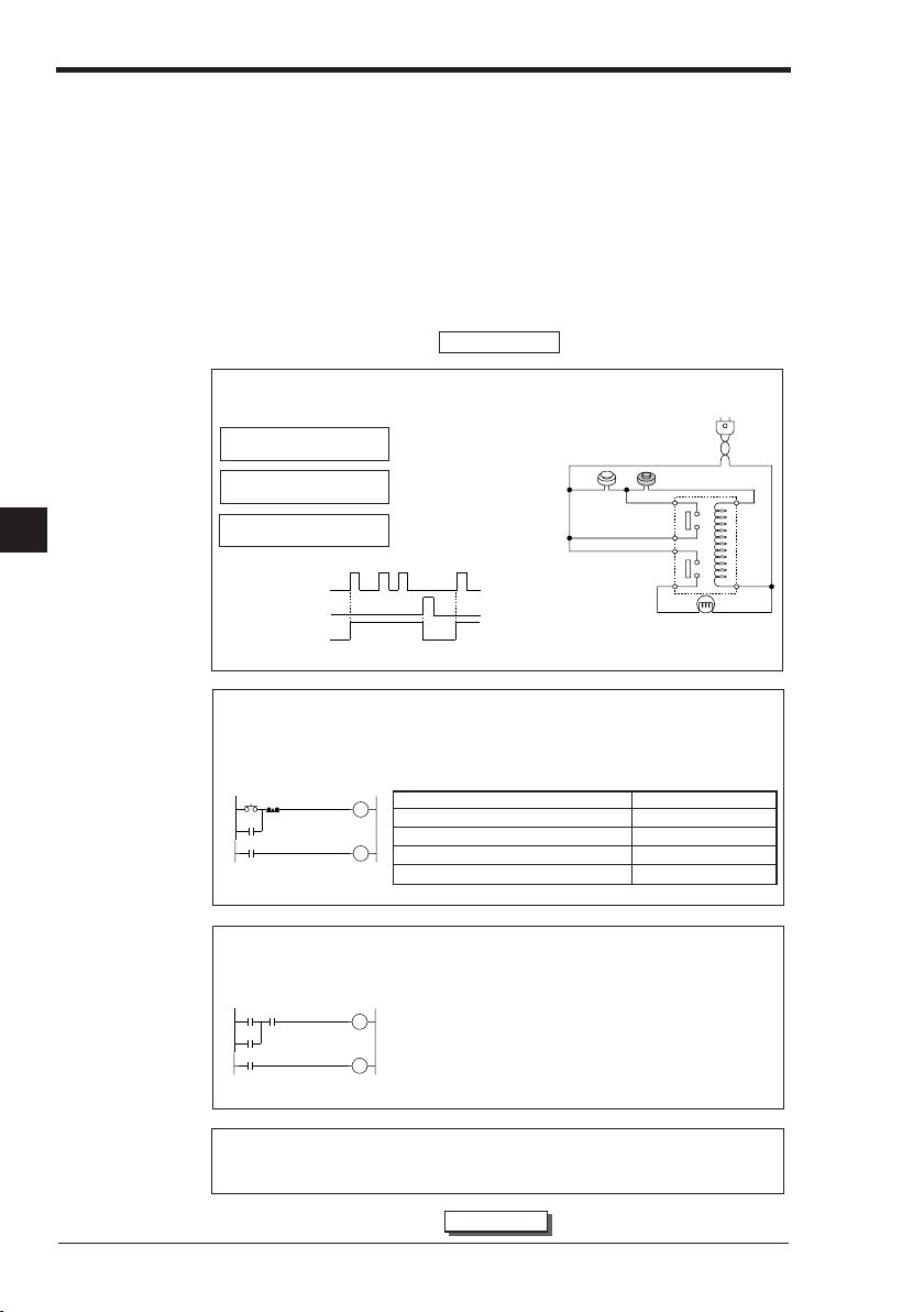
1.1 Before Creating Programs
1.1 Before Creating Programs
This section describes what you should know before creating programs and operations for the Visual KV Series.
1.1.1 Flow from Introduction to Operation
This section describes an overview of program creation procedures, functions used,
and setting items.
In the example described below, a latch circuit is created as a program for the Visual
KV Series.
Introduction
Examining contents of operations
Figure 1 shows a latch circuit which operates as follows.
Pushbutton switch PB1: ON
Pushbutton switch PB2: OFF
Pushbutton switch PB1: OFF
Pushbutton switch PB2: OFF
1
Pushbutton switch PB1: OFF
Pushbutton switch PB2: ON
Time chart
PB1 contact
PB2 contact
▲
▲
ON
OFF
ON
OFF
ON
PL
OFF
Next, a program is created that will use the same operation as this circuit to control a PLC.
Program examination
Circuit 1 shows relay symbols for the latch circuit.
Examine which contact in the Visual KV Series is used for each pushbutton switch and pilot lamp
(Table 1). When many I/O devices are required for control, expansion units should also be considered.
Circuit 1
PB1 PB2
RL
Relay (contact)
RL
Relay (contact)
Relay (coil)
➞Pilot lamp (PL) turns on.
➞Pilot lamp (PL) remains
➞Pilot lamp (PL) goes out
Table 1
RL
PL
Pilot lamp
lit even if PB1 turns
OFF.
when PB2 is set to ON.
I/O device Contact No.
Pushbutton switch PB1 (N.O. contact) Input relay (0000)
Pushbutton switch PB2 (N.C. contact) Input relay (0001)
Relay RL Internal relay (1000)
Pilot lamp PL Output coil (0500)
➞
Fig. 1
PB1 = N.O. contact switch
PB2 = N.C. contact switch
PB1 PB2
RL
(Relay)
PL
➞ ➞ ➞
3-2
Program creation
Edit a program using the "LADDER BUILDER for KV" programming support software creation tool.
Ladder diagram
0000 0001*
1000
1000
Transferring and confirming the program
Transfer the created program to the Visual KV Series, perform a test run, and then confirm operations
with the actual devices.
Chapter 1 Programming
Coding list
1000
0500
LD 0000
OR 1000
AND 0001
OUT 1000
LD 1000
OUT 0500
END
* Enter "N.O. (AND X001)" to 0001 to
use N.C. contact.
➞
Operation
Page 27
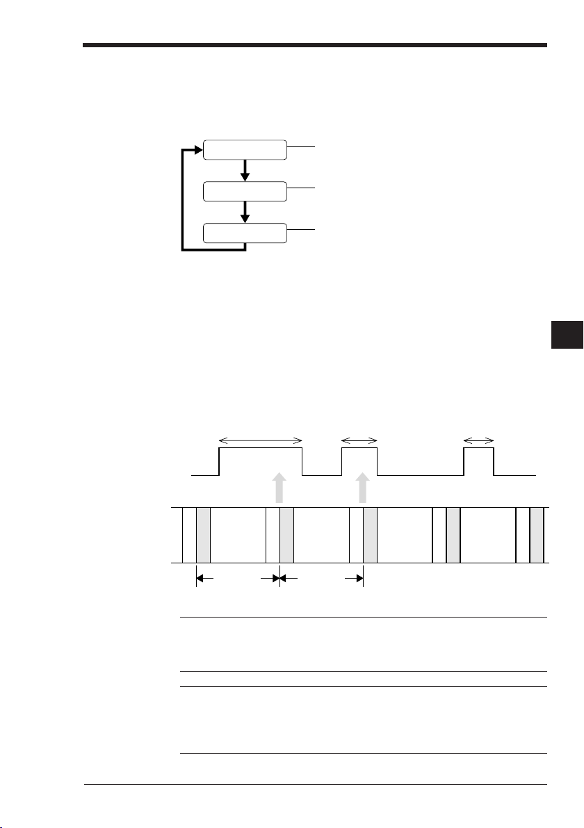
1.1.2 Scan Time
12 3
Scan time
The Visual KV Series repeatedly executes a ladder based on the sequence circuit
as follows.
Input processing
Program execution
1.1 Before Creating Programs
Writes the ON/OFF status of all input terminals to the input
memory before executing the program.
Reads the ON/OFF status of each device (internal utility relay,
timer, counter, etc.) based on the instructions, and performs
arithmetic operations.
Writes the arithmetic operation result to the output memory.
Output processing
Outputs the contents of the output memory to output terminals.
The duration of time required to perform one cycle is called the scan time (or cycle
time). The scan time varies based on program size and the instructions used in the
program.
Input response time delay
In addition to the I/O processing time, there is also an input time delay in the Visual
KV Series caused by the scan time. The input time delay is generated because the
input status can only be read during the input processing time. If the input status is
changed after input processing, the changed contents can only be read during the
next scan time.
In the figure below, 1 and 2 can be read but 3 cannot be read.
Input signal
ON
OFF
Read
Program
execution
Input processing
Output processing
Scan time
Program
execution
Input processing
Output processing
Scan time
Reference: The maximum and minimum values of the input response time are as
follows.
Maximum value: Input time constant + Scan time x 2 + Output response delay time
Minimum value: Input time constant + Scan time + Output response delay time
Note 1: When the input time constant is made small by setting the HSP instruction,
special utility relay 2813, and data memory DM1940, a signal may not be received if
its ON time is shorter than the scan time.
Note 2: The INT instruction is independent of the scan time.
Note 3: The minimum scan time is 140 µs (with the basic unit).
Read
Input processing
Output processing
Program
execution
Program
execution
Input processing
Output processing
1
1
Input processing
Output processing
Chapter 1 Programming
3-3
Page 28

1.2 User Memory
1.2 User Memory
This section describes the allowable size (capacity) of a program which can be
created in the Visual KV Series.
1.2.1 Program Capacity
When a user program is created for the Visual KV Series, the maximum number of
steps a program can contain using the mnemonic diagram varies based on the byte
count of the instructions used. The instruction byte count is determined individually
for each instruction.
➮
For more about byte counts for each instruction, refer to "2.1 Instruction List" (p.3-34).
Maximum number of lines in a program
In the KV-10xx/16xx, a program with approximately 2,000 steps can be written. In
the KV-24xx/40xx, a program with approximately 4,000 steps can be written.
• Total byte count of the memory used by instructions
bytes
• Total byte count of the memory used by objects of instructions
1
bytes / 24,000 bytes
* In the description above, a value on the left side indicates the byte count for
the KV-10xx/16xx, while a value on the right side indicates the byte count for
the KV-24xx/40xx.
* The memory occupied by objects indicates the memory required to execute a
program when operation is started.
For example, the allowable number of steps to be written can be calculated from the
memory occupied by the instructions as follows.
12,000 bytes / 3 bytes (average byte count of an instruction) = 4,000 steps
Note: If either the memory occupied by the instructions or the memory occupied by
objects of a program exceeds the specified memory capacity, the program cannot
be written or executed.
≤ 6,000 bytes / 12,000
≤ 12,000
Calculating the byte count used
The byte count used in this program can be calculated as shown in the table below.
#00020
T000
3-4
0000
0500
Line No. Instruction Operand Byte count Number of objects
00000 LD 0000 3 5
00001 OR 0500 3 4
00002 TMR 000#00020 2 7
00003 ANB T000 3 8
00004 OUT 0500 3 8
Chapter 1 Programming
T000
0500
Total 14 bytes 32 bytes
Page 29
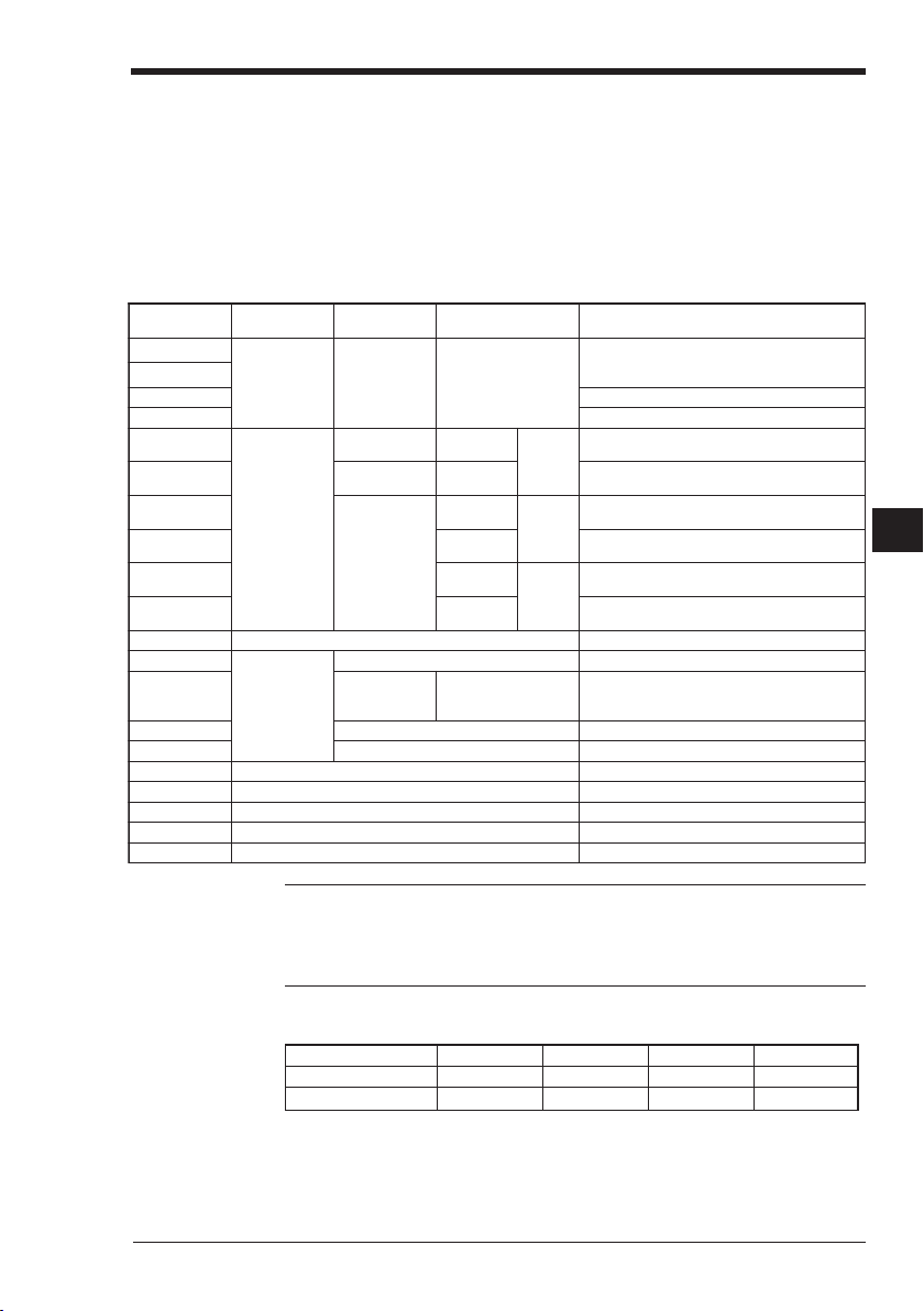
1.3 Device Configuration
1.3 Device Configuration
"Device" is a general name for relays, registers, etc. processed by instructions.
This section describes the available devices in the Visual KV Series and their
general use.
1.3.1 Device List
Relay list
.oNyaleRes u l am r oN
0000
1000
2000 –
3000 –
4000
5000
6000
7000
8000
9000
5140o t0100 sy a l e r t upn I –
0050
1050
2050 tuptuolor tnocnwod/pu-pmaR–
3050 ––
5190o t4050 syalertuptuO stniop67
5191o t0001 syalery t i l i tulanretnI s t n i op061
5182o t0002 syaleryt i l i tulaicepS s t n i op441
5192o t0092 syaleryt i l i tulaicepS aeraegarot sno i tamrof niYEKH
51971o t0003 syalery t i l i tulanretnI s t n i op441 , 2
sy a l e r t upn I
t upn i t ce r i D(
)aeradewo l l a
sy a l e r t upn I
syalertuptuO
tuptuot cer iD(
)aeradewo l l a
deeps - hg iH
)1(esu
stupnitpur retnI
3 TN I o t 0 TN I
deeps - hg i H
deeps - hg i H
–
deeps - hg i H
1r e t nuoc
tuptuo
) d ewo l l a
t upn i0r e t nuoc
t upn i1r e t nuoc
0r e t nuoc
1r e t nuoc
0r e t nuoc
1r e t nuoc
0r e t nuoc
1r e t nuoc
) 2 (esudeeps - hg iHsk r ame R
noi srevniyt i raloP(
serutpactupnI
deeps - hg i H
t upn i
deeps - hg i H
deeps - hg i H
t upn i
deeps - hg i H
deeps - hg i H
t upn i
deeps - hg i H
t up t uo0r e t nuocdeeps - hg i Hst n i op07
yc neuqer fde i f i c epS
t up t uoes l up
. 0 1 - VK
esahpA
esahpB
t eser P
deeps - hg i hf oesahpBsano i t cnu fyehT
n i sya l e ry t i l i t uf ono i t ac i f i cepshguo r h ts r e t nuoc
–
–
–
–
–
–
–
1
1
Note 1: The ON/OFF status of the set functions is always cleared when the operation mode is changed from PROGRAM to RUN. However, special utility relays 2700
to 2715 are held even when the operation mode is changed from PROGRAM to
RUN or when the power is turned off.
Note 2: Internal utility relays can be held by setting the MEMSW instruction
List of I/O relays in basic units
Model KV-10xx KV-16xx KV-24xx KV-40xx
Basic input relays 0000 to 0005 0000 to 0009 0000 to 0015 0000 to 0107
Basic output relays 0500 to 0503 0500 to 0505 0500 to 0507 0500 to 0515
Chapter 1 Programming
3-5
Page 30
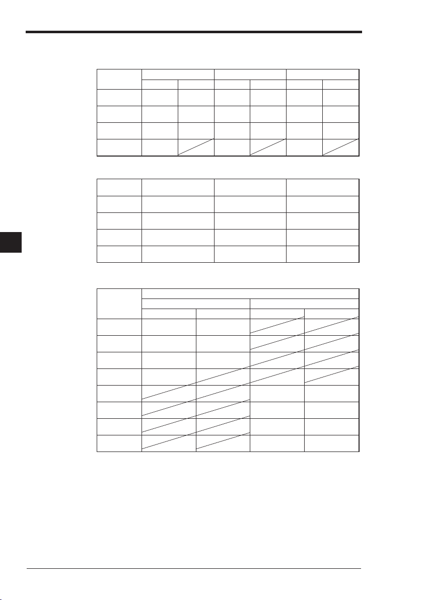
1.3 Device Configuration
List of relays in expansion units
■ Input units
redro
t upn i t s1
e l udom
e l udom
e l udom
e l udom
■ Output units
redro
e l udom
e l udom
1
e l udom
e l udom
■ I/O units
redro
t upn i t s1
e l udom
e l udom
e l udom
e l udom
e l udom
e l udom
e l udom
e l udom
* Relay Nos. of expansion units are automatically assigned in the order of connection.
* The connection order is counted only for input and output units. When I/O units are
connected, they are counted as input units and output units separately.
no i t ce nnoC
t upn idn 2
t upn id r 3
t upn ih t 4
no i t ce nnoC
tuptuots1
t up t uodn 2
tuptuodr3
tuptuoht4
no i t ce nnoC
t upn idn 2
t upn id r 3
t upn ih t 4
tuptuots1
t up t uodn 2
tuptuodr3
tuptuoht4
X4E - VKX8E - VKX6 1 E - VK
0 4 - VK
42/61/01-VK
301o t001302o t002701o t001702o t002511o t001512o t002
302o t002303o t003702o t002703o t003512o t002513o t003
303o t003304o t004703o t003704o t004513o t003514o t004
304o t004704o t004514o t004
R/ )P(T4E-VKR/ )P(T8E-VKR/ )P(T61E-VK
306o t006706o t006516o t006
307o t007707o t007517o t007
308o t008708o t008518o t008
309o t009709o t009519o t009
sya l e r t upn Isyal ertuptuO
42/61/01-VK04-VK42/61/01-VK04 - VK
301o t001302o t002
302o t002303o t003
303o t003304o t004
304o t004
0 4 - VK
42/61/01-VK
)P(T /RX4E-VK
306o t006306o t006
307o t007307o t007
308o t008308o t008
309o t009309o t009
0 4 - VK
42/61/01-VK
3-6
Chapter 1 Programming
Page 31

1.3.2 Relay No.
The relay No. configuration is shown below.
Address No.
Address Nos. are assigned to basic units, input expansion units, output expansion
units, and I/O expansion units. Zero to 4 are assigned to input units, while 5 to 9 are
assigned to output units. Address Nos. assigned in a unit vary based on the number
of I/O terminals and the connection position of the unit.
Basic units
Input expansion units KV-E8X 1 to 4*
Output expansion units KV-E8R/E8T(P) 6 to 9
I/O expansion units KV-E4XR/E4XT(P) 1 to 4*, 6 to 9
* 2 to 4 in KV-40xx
■ Address No. assignment procedure
• The address No. is represented as a number 0 to 9.
• Address Nos. 0 to 4 are provided for inputs, while address Nos. 5 to 9 are provided for outputs.
1.3 Device Configuration
Channel No.
12515
Contact No.
(00 to 15)
Address No.
(Input: 0 to 4, output: 5 to 9)
Model Address Nos.
KV-10xx 0, 5
KV-16xx 0, 5
KV-24xx 0, 5
KV-40xx 0, 1, 5
kV-E4X 1 to 4*
KV-E16X 1 to 4*
KV-E4R/E4T(P) 6 to 9
KV-E16R/E16T(P) 6 to 9
1
1
Chapter 1 Programming
3-7
Page 32

1.3 Device Configuration
Contact No.
• Contact Nos. are input/output terminal Nos. of basic units, input expansion units,
output expansion units, and I/O expansion units.
• The contact No. is represented as a number 0 to 15.
Example
In the KV-E4X, with 4 input terminals, the contact Nos. are 0 to 3. In the KVE16T(P), with 16 input terminals, the contact Nos. are 0 to 15.
• In a unit with 16 or more terminals, the contact No. of the 17th terminal returns to
0 and its address No. is increased by 1.
Example
In the KV-40AR, with 40 terminals (24 input and 16 output terminals), address
No. 0 is assigned to input terminal Nos. 1 to 16 and address No. 1 is assigned to
input terminal Nos. 17 to 24
Channel No.
The channel No. is the higher order digit in the contact No.
1
1.3.3 Assigning Relay Nos.
When assigning relay Nos., the unit No. is based on the connection position of the
unit, and the address No. is determined based on the unit type and I/O contacts.
a) KV-16AR
Basic unit
Input: 10 points
Output: 6 points
b) KV-E4X Input
expansion
unit
Input: 4 points
c) KV-E8R Output
expansion unit
Output: 8 points
3-8
With the connections above, the relay Nos. for each unit are assigned as shown in
the table below.
Unit Assigned relay Nos.
a) KV-16AR 0000 to 0009 (input) and 0500 to 0505 (output)
b) KV-E4X 0100 to 0103 (input)
c) KV-E8R 0600 to 0607 (output)
Chapter 1 Programming
Page 33

1.3.4 Input Relays
Input relays receive ON/OFF signals sent from external input equipment.
Note 1: Input relays function as contacts in programs. They cannot be used as relay
coils (outputs).
Note 2: There is no restriction of the contact type (N.O. or N.C.) used, the order the
relay Nos. are used, or the number of relays used.
Basic unit
■ Input relay time constant
Though the time constant is usually 10 ms ±20%, it can be changed using the
following settings.
• When the HSP instruction is used: 10 µs ±20%
• While special utility relay 2813 remains ON, the time constant can be changed in
7 steps by setting data memory DM1940 as follows.
When DM1940 is set to 0: 10µs ±20%
➮
For more about changing the input time constant, refer to "1.4.1 Input Time Constant Change
Function" (p.3-23).
■ Hardware input (independent of scan time)
• High-speed counter
When the time constant is set to 10 µs using the HSP instruction or data memory
DM1940 (only while special utility relay 2813 remains ON), the maximum input
response of input relays 0004 and 0005 of CTH0 and CTH1 becomes 30 kHz.
• INT instruction: 0000 to 0003
This instruction can receive any signal without regard to the scan time as far as
the signal ON time is longer than the input time constant.
1.3 Device Configuration
1: 20 µs ±20%
2: 500 µs ±20%
3: 1 ms ±20%
4: 2.5 ms ±20%
5: 5 ms ±20%
6: 10 ms ±20%
Never set a numeric value of 7 or larger.
1
1
➮
"HSP instruction" (p.3-86), "INT instruction" (p.3-192), "4.1 High-speed Counter Instructions"
(p.3-204)
Note 1: While special utility relay 2813 remains ON, the input time constant can be
specified for all input relays in a basic unit.
Note 2: Never enter a number of 7 or larger to data memory DM1940.
Note 3: The input time constant specified by data memory DM1940 becomes
effective at the rising edge of special utility relay 2813. To change the input time
constant, first change data memory DM1940, then set special utility relay 2813 to
OFF and ON again. Or change the operation mode of a KV basic unit from PROGRAM to RUN.
Note 4: If the HSP instruction and special utility relay 2813 are used at the same
time, priority is given to the HSP instruction.
Note 5: Only when a high-speed counter input or INT instruction is given, available
input signals do not depend on the scan time.
Chapter 1 Programming
3-9
Page 34

1.3 Device Configuration
Expansion unit
■ Input relay time constant
By setting special utility relays 2609 to 2612 to ON, the time constant in input expansion units can be set to 10 µs.
* 9062
0162
1162
2162
* Not available with the KV-40xx
1.3.5 Output Relays
Output relays output the program execution results to the outside. There are two
types of outputs, relay and transistor.
yt i l i tulaicepS
.oNyaler
5110o t0010. soNy a l e rh t i w
5120o t0020. soNy a l e rh t i w
5130o t0030. soNy a l e rh t i w
5140o t0040. soNy a l e rh t i w
no i t cnuF
t i nuno i s napxet upn i f ot na t s nocemi t t upn I
t i nuno i s napxet upn i f ot na t s nocemi t t upn I
t i nuno i s napxet upn i f ot na t s nocemi t t upn I
t i nuno i s napxet upn i f ot na t s nocemi t t upn I
01: NO, sm01: FFO µs
01: NO, sm01: FFO µs
01: NO, sm01: FFO µs
01: NO, sm01: FFO µs
1
Output operation time
Note 1: Output relays function as contacts and relay coils in programs.
Note 2: There is no restriction of the contact type (N.O. or N.C.) used, the order the
relay Nos. are used, or the number of relays used.
• Transistor output
OFF ➞ ON: 50 µs or less (10 µs or less in 500 to 502)
ON ➞ OFF: 250 µs or less (10 µs or less in 500 to 502, 100 µs or less for other
outputs in the basic unit)
• Relay output
OFF ➞ ON: 10 ms or less
ON ➞ OFF: 10 ms or less
epy t t up tuor o t s i sna r Tepy ttuptuoyal eR
)P(TD/ )P(TA01-VK)P(TD/ )P(TA61-VKRD/RA01-VKRD/RA61-VK
T4E-VK)P(T8E-VKR4E-VKR8E-VK
)P(TD/ )P(TA42-VK)P(TD/ )P( TA04-VKRD/RA42-VKRD/RA04-VK
)P(T61E-VK)P(TX4E-VKR61E-VKRX4E - VK
Note 1: When programming direct clock pulses, output relays 0500 and 0501 are
used to output pulses in a transistor-type output unit.
Note 2: When the ramp-up/down control function is used, output relay 0502 outputs
positioning pulses in a transistor-type output unit.
➮
"Chapter 5. Positioning Control" (p.3-253)
Note 3: When the specified frequency pulse output function is used, output relay
0501 outputs pulses in a transistor-type output unit.
➮
"4.5.1 Specified Frequency Pulse Output Function" (p.3-228)
3-10
Chapter 1 Programming
Page 35

1.3.6 Internal Utility Relays
In a relay circuit, when one relay contact is used twice or more inside the circuit, a
multi-pole relay with the same number of poles as the number used may be needed.
Internal utility relays function only in programs, and eliminate the complexity of relay
circuits to facilitate circuit design.
Note 1: Internal utility relays function as contacts and relay coils in programs.
Note 2: There is no restriction of the contact type (N.O. or N.C.) used, the order the
relay Nos. are used, or the number of relays used.
Retentive function of internal utility relays
Except for internal utility relays, all relays turn OFF when the operation mode is
changed or when operation is stopped via a power shutdown. When operation is
restarted, all relays remain OFF except relays whose input condition is ON. However, internal utility relays can be set using the MEMSW (memory switch) whether or
not they are to be retained. (Internal utility relays 2700 to 2715, however, are always
retained.)
When an internal utility relay is set to be retained, its ON/OFF status is stored even if
the power is turned off. By using the retained relay all clear function (FUN65), all
relays which are set to be retained can be set to OFF.
➮
For more about setting the memory switch, refer to "MEMSW instruction" (p.3-92).
Application example of a retentive function: Lift vertical movement control
Internal utility relays 1000 and 1001 are set to be retained.
When the upper/lower limit switch turns ON, the direction of lift movement is
inverted. Even if the power is turned off while the lift is moving up (or down), the lift
continues to move up (or down) when the power is turned on again.
Upper limit
switch
(0000)
Lower limit
switch
(0001)
Move-down
(0500)
Move-up
(0501)
1.3 Device Configuration
MEMSW
0000
1000 #00010
0001
1001 #00010
T000
T001
0001
0501
$0004
1000
T000
10010000
T001
0500
05010500
END
ENDH
1
1
Note: The retentive function is effective only when internal utility relays retained by
the self-retentive circuit or the SET/SFT/KEEP instruction are also retained by the
memory switch.
Internal utility relays are not retained in the program shown below.
0000
1001
Chapter 1 Programming
3-11
Page 36

1.3 Device Configuration
1.3.7 Special Utility Relays
Each special utility relay has a unique function. By using special utility relays effectively, programs can be simplified and program control improved.
Note 1: A special utility relay can be used as many times as desired in one program.
Note 2: Special utility relays dedicated for reading can be used as contacts, but
cannot be used as outputs.
➮
For more about relays dedicated for reading, refer to "1.3.8 Special Utility Relay List" (p.3-14).
Description
Relay 2002: Always ON
By setting an output relay to ON using relay 2002, the output relay can be used as a
"running indicator output".
2002
2002
1
Set the input time constant of relay 0100 to 10 µs.
Transfer the ON/OFF status data of channel 0000 to DM0000.
HSP
0100
00000
LDA
DM0000
STA
Relay 2003: Always OFF.
Opposite that of relay 2002, use relay 2003 where it is not required to be turned on.
For example, when using only the up function of an up/down counter, use relay 2003
in the DW (down) input.
Relays 2004, 2005 and 2006: Clock pulse
For each relay, the time ratio is "ON:OFF = 1:1". (Accordingly, the ON time of relay
2005 is 0.05 sec/pulse.)
However, because these relays depend on the scan time, error as much as the scan
time is generated.
• By combining an output relay, an "intermittent output" can be made.
• By using relay 2006 as input for a counter, the counter can be used as a longterm timer.
1000
C000
1000 turns ON at every hour.
#03600
C000
2006
1000
Relay 2007: Remains OFF during only one scan when operation is started.
This relay can be used when a signal needs to be sent after a specific period
(equivalent to one scan) after operation is started. This relay can also be used for
an initial reset at the start of operation.
After one scan, this relay remains ON.
3-12
When operation is started, this relay returns
the current value of C005 to 0.
Chapter 1 Programming
1000
2007
#00100
C005
0000
Page 37

1.3 Device Configuration
Relay 2008: Remains ON during only one scan when operation is started.
This relay can be used for an initial reset at the start of operation.
After one scan, this relay remains OFF.
0000
1000
2008
When operation is started, this relay sets all internal
utility relays used by the SFT instruction to OFF.
SFT
D
1100
CLK
1100
RES
2008
When operation is started, this relay returns the current
value of DM0000 to 0.
#00000
LDA
DM0000
STA
Relay 2813: Sets the input time constant of the CPU.
While relay 2813 remains ON, the input time constant of a basic unit can be set
using the value of DM1940.
1
1
Chapter 1 Programming
3-13
Page 38

1.3 Device Configuration
1.3.8 Special Utility Relay List
Special relays and arithmetic operation flags
➮
"1.3.7 Special Utility Relays" (p.3-12)
.oNyaleRno i t cnuF
* 2002 .NOsyawl A
* 3002 .FFOsyawlA
* 4002 )%05: e l cy cy t ud (es l upk co l cs - 10 . 0
* 5002 )%05:el cycytud(esl upkcolcs-1.0
* 6002 )%05:el cycytud(esl upkcolcs-0.1
* 7002 .put ratsret fanacstsr i fgn i rudFFOsn iameR
* 8002 .put ratsret fanacstsr i fgn i rudNOsn iameR
* 9002
* 0102 .0s inoi t arepoc i temh t i raf ot l usernehwNOsnruT
* 1102 . ev i t i sops ino i t a r epoc i t emh t i r af ot l use rnehwNOsn r uT
* 2102 . r o r r enas e t a r enegno i t a r epoc i t emh t i r ananehwNOs n r uT
* Read-only relay.
Special utility relays for high-speed counter(0)
1
➮
"Chapter 4. High-Speed Counters" (p.3-203)
.oNyaleRno i t cnuF
* 0012
* 1012
* 2012
3012
4012
5012
6012
7012
8012
9012
0112
1112
2112
3112
4112
* Read-only relay.
e d om
3112FFONOFFONO
4112FFOFFONONO
.NOsnrut
. NOs n r u t 0CTC
. NOs n r u t 0CTC
. NOs n r u t 1CTC
. NOs n r u t 1CTC
.NOsnrut
noi taci lpi t luM
es l up12x4xse s l u p2
Note: Never use special utility relays that are not shown above.
. de t a r enegs iwo l f r ev o
1(0HTCro fy lnodesukco lclanretn I µ )s
01 (0HTCr o fy l node suk co l cl an r e t n I µ )s
001 (0HTCr o fy l node suk co l cl an r e t n I µ )s
.NOsnrut0CTCrotarapmoc
.NOsnrut0CTCrotarapmocemi t
.NOsnrut1CTCrotarapmoc
.NOsnrut1CTCrotarapmocemi t
0CTCrotarapmocnehw0HTCforael cci tamotuA
nehw0050o t t up t uot ce r i ds t imr ep / s t i b i ho r P
r o t a r apmocnehwFFOo t t ess i 0050o t t up t uot ce r iD
r o t a r apmocnehwNOo t t ess i0050o t t up t uot ce r i D
hcaedesrevers i0050ottuptuofosutat sFFO/NO
nehw0050o t t up t uot ce r i ds t imr ep / s t i b i ho r P
r o t a r apmocnehwFFOo t t ess i 0050o t t up t uot ce r iD
r o t a r apmocnehwNOo t t ess i0050o t t up t uot ce r i D
hcaedesrevers i0050ottuptuofosutat sFFO/NO
1CTCrotarapmocnehw0HTCforael cci tamotuA
.0HTCrotarapmocrofedomnoi taci lpi t lumstceleS
N OF F ONOF FO
ses l up2:NO4x:NO2x:FFOes l up1: FFO
nanehwr oev i t agens ino i t a r epoc i t emh t i r af ot l use rnehwNOsn r uT
de r ae l C: NO
derael ct oN:FFO
det ibihorP:NO
de t t imreP:FFO
FFOotteS:NO
FFOottestoN:FFO
NOo t t e S : NO
NOottestoN:FFO
des r eveR:NO
des r ever t oN:FFO
det ibihorP:NO
de t t imreP:FFO
FFOotteS:NO
FFOottestoN:FFO
NOo t t e S : NO
NOottestoN:FF
des r eveR:NO
des r ever t oN:FFO
de r ae l C: NO
derael ct oN:FFO
3-14
Chapter 1 Programming
Page 39

Special utility relays for high-speed counter(1)
➮
"Chapter 4. High-Speed Counters" (p.3-203)
.oNyaleRno i t cnuF
* 0022
* 1022
* 2022
3022
4022
5022
6022
7022
8022
9022
0122
1122
2122
3122
4122
* Read-only relay.
e d om
3122 FFONOFFONO
4122 FFOFFONONO
Note: Never use special utility relays that are not shown above.
.NOsnrut
.NOsnrut2CTCrotarapmoc
. NOs n r u t 2CTC
. NOs n r u t 2CTC
.NOsnrut3CTCrotarapmoc
. NOs n r u t 3CTC
. NOs n r u t 3CTC
.NOsnrut
noi taci lpi t luM
es l up12x4xse s l u p2
1.3 Device Configuration
1(1HTCro fy lnodesukco lclanretn I µ )s
01 (1HTCr o fy l node suk co l cl an r e t n I µ )s
001 (1HTCr o fy l node suk co l cl an r e t n I µ )s
2CTCrotarapmocnehw1HTCforael cci tamotuA
nehw1050o t t up t uot ce r i ds t imr ep / s t i b i ho r P
r o t a r apmocnehwFFOo t t ess i 1050o t t up t uot ce r iD
r o t a r apmocnehwNOo t t ess i1050o t t up t uot ce r i D
.NOsnrut2CTCrotarapmocemi t
.NOsnrut3CTCrotarapmocemi t
hcaedesrevers i1050ottuptuofosutat sFFO/NO
nehw1050o t t up t uot ce r i ds t imr ep / s t i b i ho r P
r o t a r apmocnehwFFOo t t ess i 1050o t t up t uot ce r iD
r o t a r apmocnehwNOo t t ess i1050o t t up t uot ce r i D
hcaedesrevers i1050ottuptuofosutat sFFO/NO
3CTCrotarapmocnehw1HTCforael cci tamotuA
NOF F ONOF FO
.1HTCrotarapmocrofedomnoi taci lpi t lumstceleS
ses l up2:NO4x:NO2x: FFOes l up1: FFO
de r ae l C: NO
derael ct oN:FFO
det ibihorP:NO
de t t imreP:FFO
FFOotteS:NO
FFOottestoN:FFO
NOo t t e S : NO
NOottestoN:FFO
des r eveR:NO
des r ever t oN:FFO
det ibihorP:NO
de t t imreP:FFO
FFOotteS:NO
FFOottestoN:FFO
NOo t t e S : NO
NOottestoN:FFO
1
des r eveR:NO
de r ae l C: NO
1
des r ever t oN:FFO
derael ct oN:FFO
Other special utility relays
.oNyaleRno i t cnuF
0032
1032
3032
4032
5032
6032
7032
8032
9032
0132
4132
5132
* Read-only relay.
delbasidstuptuolanretxE
) 5190o t0050s t up t uo (
delbasidstupnihser ferlanretxE
) 5140o t0000s t upn i (
edomem i tnac st na t s noC
) 92MTn ieu l avt ese rpe t i rw(
. emi tnacst na t snoct eser p
t up t uoe s l upy cneuqe r fde i f i cepS
.NOden r u tnehwr ev i r dr o t omspo t S
. no i t a r epohc t i wsmacr o fga l f t r a t S
sdeecx eemi tnac snehwnacsenor o fNOs n i ameR
. no i t a r epor e t nuocy cneuqe r f r o fga l f t r a t S
t up t uoe s l upy cneuqe r fde i f i cep sr o fga l f r o r r E
. no i t cu r t sn i t pu r r e t n i ybFFOden r u tnehwse i cneg r eme
.noi tarepohct iwsmacnisruccoror renanehwNOsnruT
Chapter 1 Programming
de l bas i D:NO
delbasidtoN:FFO
de l bas i D:NO
delbasidtoN:FFO
de l banE:NO
de l bas i D: FFO
de l banE:NO
de l bas i D: FFO
nirev i rdrot omspotS.noi t areponisirevi rdrot omnehwNOsnruT
. ) egdegn i s i r t ano i t ce t ed (NOden r u tnehwr ev i r dr o t oms t r a t S
3-15
Page 40

1.3 Device Configuration
.oNyaleRno i t cnuF
0042
FFOteserplanret xEFFO
FFOdesut onNOFFONO
1042
2042
F FO
FFONOFFONO
3042
4042
F FO
FFONOFFONO
5042
egdegn i s i r t A
egdegn i s i r t A
langislanretxe0HTCfognimiT
TNIfoyt i raloptpur retnI
F FO
1TNIfoyt i raloptpur retnI
F FO
NO
egdegn i l l a f tA
NO
egdegn i l l a f tA
NO
egdegn i l l a f tA
NO
egdegn i s i r t A
egdegn i s i r t A
egdegn i s i r t A
l eveL
NO
NO
segdeh t obt A
segdeh t obt A
6042 r e t nuocgn i rs at es0HTCteS: NOte s t o N: F FO
7042
8042
FFOteserplanret xEFFO
FFOdesutonNOFFONO
9042
0142
F FO
FFONOFFONO
1142
2142
F FO
FFONOFFONO
3142
1
4142 r e t nuocgn i rs at es1HTCteS: NOte s t o N: F FO
egdegn i s i r t A
egdegn i s i r t A
5142
. l aususat upn iBesahpesU: FFO
teserpl anre txe1HTCfognimiT
2TNIfoyt i raloptpur retnI
F FO
3TNIfoyt i raloptpur retnI
F FO
. l aususaBesahpesU: FFO
. put nuocsy awl adnat upn iBe sahpe r ong I :NO
NO
egdegn i l l a f tA
NO
egdegn i l l a f tA
NO
egdegn i l l a f tA
. put nuocsy awl adnat upn iBe sahpe r ong I :NO
. edomno i t ac i l p i t l umono t t e ss i0HTCnehwt upn iBes ahpe r ong I
NO
egdegn i s i r t A
egdegn i s i r t A
egdegn i s i r t A
l eveL
NO
NO
segdeh t obt A
segdeh t obt A
. edomno i t ac i l p i t l umono t t e ss i1HTCnehwt upn iBes ahpe r ong I
0052 . deng i s sas i l enape ca f r e t n i r o t a r epo02D-VKno] 1F [hc t i wsdez i mo t s uC
1052 . deng i s sas i l enape ca f r e t n i r o t a r epo02D-VKno] 2F [hc t i wsdez i mo t s uC
2052 . deng i s sas i l enape ca f r e t n i r o t a r epo02D-VKno] 3F [hc t i wsdez i mo t s uC
3052 . deng i s sas i l enape ca f r e t n i r o t a r epo02D-VKno] 4F [hc t i wsdez i mo t s uC
4052
5052
6052
7052
8052
9052
0152
1152
. deng i s sa
. deng i s sa
. deng i s sa
. deng i s sa
r o t a r eponeewt ebegnahcs t i mr eP
02D- VKf oedomec i veddnaedom
. l enape ca f r e t n i r o t a r epo
. edomme t s ysdnaedom
l enapeca f r e t n i
ecaf retnirotarepo02D-VKehtst imreP
r o t a r eponeewt ebde t f i hsebo t l enap
eh t r o fegaugna l ya l ps i deh t se i f i c epS
l enapeca f r e t n i r o t a r epo02D- VK
r o t a r epo02D-VKeh t r o fpeebeh ts t eS
d e t t i m r e P : NO
d e t t i m r e P : NO
esenapaJ: NOhs i l g n E: F FO
peebe sU: NOpeeboN: FFO
s i l enape ca f r e t n i r o t a r epo02D- VKno1pma l r o t ac i dn ide z imo t s uC
s i l enape ca f r e t n i r o t a r epo02D- VKno2pma l r o t ac i dn ide z imo t s uC
s i l enape ca f r e t n i r o t a r epo02D- VKno3pma l r o t ac i dn ide z imo t s uC
s i l enape ca f r e t n i r o t a r epo02D- VKno4pma l r o t ac i dn ide z imo t s uC
t oN : F FO
de t t imr ep
OtoN: FF
de t t imr ep
2152 me t sysr o fdev reseR
3152 me t sysr o fdev reseR
5152
f os t ne t noc (egassemr esuasya l ps i D
wodn iWs sec cAeh tn i ) 0591MD
ya l ps i D: NO
egas sem
t o no D: F FO
egassemya l ps i d
3-16
Chapter 1 Programming
Page 41

1.3 Device Configuration
.oNyaleRno i t cnuF
9062
0162
1162
2162
3162 t cennoc s i dno i snapxet at upn i f ogn i r ae lC
2172
4172
5172 .noi tareponisihct iwsmacel ihwNO
0082 . ) gn i dnese l i hwNOsn i ame r (At r opno i t ac i nummo co tdnes l ang i sk ae rB
1082
2082
3082
4082 ) . gn i dnesgn i r udNOs n i ame r ( t r a t sdnesa t adt x e tAt r opno i t ac i nummoC
5082 . ) gn i dnese l i hwNOsn i ame r (Bt r opno i t ac i nummo co tdnes l ang i sk ae rB
6082
7082
8082
9082 ) . gn i dnesgn i r udNOs n i ame r ( t r a t sdnesa t adt x e tBt r opno i t ac i nummoC
2182 . y r e t t abpukc abh t i ws r uccoy t i l amr onbananehwNOs n r uT
3182
4182 .det ibihorperasyekelpi t luM:noi tcur tsniYEKH
5182 .dehs ini fsinacS:noi tcurtsniYEKH
. NOs i
5192o t0092 .aeraegaro tsno i tamrofniYEKH
5110o t0010. soN
5120o t0020. soN
5130o t0030. soN
5140o t0040. soN
. )noi tcurtsniPSH
lamroN:FFOror ret cennocs iD
t i nude t cennocn ino i t cenno cs i D: NO
desut oN: FFOdesU:NO
.atadtxetgniv iecerel ihwnacs
t i uc r i cno i t c e r r oct upn ideep s - hg i hf oesU
.atadtxetgniv iecerel ihwnacs1
.NOs i8082y a l e rr o6082ya l e r
. sm01o t t na t s nocem i t t upn i s t eS: FFO
ya l e rh t i wt i nuno i snap xet upn i f ot na t sno cemi t t upn I
ya l e rh t i wt i nuno i snap xet upn i f ot na t sno cemi t t upn I
ya l e rh t i wt i nuno i snap xet upn i f ot na t sno cemi t t upn I
ya l e rh t i wt i nuno i snap xet upn i f ot na t sno cemi t t upn I
r o r r eev i ece ra t adt xe tAt r opno i t ac i nummoC
. r o r r eec na t pec caa t adt x e tBt r opno i t a c i nummoC
r o r r eev i ece ra t adt xe tBt r opno i t ac i nummoC
Note: Never use special utility relays that are not shown above.
0 1 : NO µs
0 1 : NO µs
0 1 : NO µs
0 1 : NO µs
s m0 1 : F F O
s m0 1 : F F O
s m0 1 : F F O
s m0 1 : F F O
deraelC:FFO
de r ae l ct oN: NO
dero tss iaeras ihT
eh tnehwnev e
s iedomno i t a r epo
mo r fdegnahc
, NURo tMA RGORP
s i r ewopeh tnehwr o
t uoh t i w( f f oden r u t
eh tybde t ce f f agn i eb
. )noi tcur tsniWSMEM
t o ns i a e r as i h T
eh t f inevede r ae l c
raelCl lAyaleryt i l i tu
.detavi t casino i tcnuf
s ia e r as i h t , r e v ewoH
1
1
l l Ananehwde r ae l c
de t ucexes i rae lC
agn i r e t s i ge r t uoh t i w
.margorp
y l nogn i r udNOs n i ame rdna,At r opno i t ac i nummo cmo r fa t adt xe tse v i ec eR
y l nogn i r udNOs n i ameR. r o r r eec na t pec caa t adt x e tAt r opno i t a c i nummoC
3082ya l e r r o1082ya l e rr eh t i ee l i hwdev i ece rs ia t adt xe tnehwNOna c s1
. s ruccoro r r eev i ece ra t adt xe tanehwnacs1y l nogn i r udNOsn i ameR
1y l nogn i r udNOsn i ame rdna, a t adt xe tBt r opno i t a c i nummocsev i eceR
e l i hwdev i ec e rgn i ebs ia t adt xe tnehwNOna cs1y l nogn i r udNOsn i ameR
. s ruccoro r r eev i ece ra t adt xe tanehwnacs1y l nogn i r udNOsn i ameR
ybdesus t upn i t pe cxe (e l udomc i s abn is t upn i l l ao t t na t snocemi t t upn is t eS
. t na t snocemi t t upn i sen i mr e t edneh t , 0491MDn ide r o t seu l avo ts r e f eR: NO
Chapter 1 Programming
3-17
Page 42

1.3 Device Configuration
1.3.9 Timers and Counters
Timers and counters can be set in a program, and their outputs can be used as
contacts elsewhere in the program. [There is no restriction on the contact type (N.O.
or N.C.) and the order of use.]
A same number can be assigned to only one timer or counter. For example, T005
and C005 cannot be used in the same program.
Timer/Counter list
r em i T
r e t nuoC
Description
1
■ Timers
• When 0.1-s timers (TMR) and high-speed 0.001-s timers (TMS) are used as
contacts, the "Tnnn" No. is used for both types. However, the form for setting is
different. "TMRnnn#ddddd" is used for 0.1-s timers, "TMHnnn#ddddd" is used for
high-speed 0.01-s timers, and "TMSnnn#ddddd" is used for high-speed 1-ms
timers (nnn = timer No, ddddd = timer set value).
• In a single program, different timer Nos. must be assigned to each of TMRnnn,
TMHnnn, and TMSnnn.
• When the PLC is stopped, all timers are reset and their current values become
equivalent to set values.
■ Counters
• When counters (C) and up/down counters (UDC) are used as contacts, the
"Cnnn" No. is used for both types. However, the form for setting is different.
"Cnnn#ddddd" is used for counters, while "UDCnnn#ddddd" is used for up/down
counters.
• In one program, different numbers must be assigned to each of the counters and
up/down counters.
• Even when operation is stopped, each counter stores whatever value it has at
that time.
➮
"TMR instruction" (p.3-67), "TMH instruction" (p.3-68), "TMS instruction" (p.3-69), "C instruction" (p.3-
72), "UDC instruction" (p.3-76).
ema Ntc a t n oC
) remi ts-1. 0(remi T
r em i tdeeps - hg i H
) remi ts-10.0(
r em i tsm- 1deep s - hg i H
) remi ts-100. 0(
r e t nuoC
retnuocnwod/pU942o t000CDU
l i oC
)noi tcurtsni (
942o t000RMT
942To t000T
942Co t000C
942o t000HMT
942o t000SMT
942o t000C
r e bmu N
latotni052
3-18
■ High-speed counters and high-speed counter comparators
The Visual KV Se ries is equipped with two high-speed counters (CTH0 and CTH1)
and four high-speed counter comparators (CTC0, CTC1, CTC2, and CTC3) with a
30-kHz input response speed (frequency), two phases, and size of 16 or 24 bits.
Note: When a high-speed counter or high-speed counter comparator will be used as
a 24-bit device, a set value is required to be stored in a data memory using the
MEMSW instruction.
➮
For details about high-speed counters and high-speed counter comparators, refer to "Chapter 4 Highspeed Counters" (p.3-203).
Chapter 1 Programming
Page 43

1.3.10 Data Memories
Data memories store various types of data.
Data memories are not usually used in a program that consists of contacts, coils,
timers, and counters. When arithmetic instructions are used, however, data memories can be used to store data for arithmetic operations as well as the results of
arithmetic operations.
:
. o NM Dno i t p i r cseD
9 9 9 MDo t 0 MD
9901MDo t0001MD
9911MDo t0011MD
9921MDo t0021MD
9931MDo t0031MD
0041MD
1041MD
2041MD
3041MD
4041MD
5041MD
0741MD
0841MD
1841MD
2841MD
3841MD
4841MD
5841MD
6841MD
6761MD
edom
7041MD / 6041MD
9041MD / 8041MD
9641MD / 8641MD
9741MDo t1741MD
9941MDo t7841MD
9651MDo t5651MD
9751MDdna8751MD
9951MDo t0851MD
9961MDo t4661MD
5761MDo t0761MD
At ropev i ece r t xeT
At r opdnest xeT
Bt ropev i ece r t xeT
Bt r opdnest xeT
0HTCo t
FFO/NOsn ru t
FFO/NOsn ru t
FFO/NOsn ru t
) 000 , 05
) 000 , 05
)000,4ot0(
) 535 , 56o t0 (
) 535 , 56o t0 (
edomr o t a r epon i
1.3 Device Configuration
) r esuybdesuebnac (de i f i cepst oN
.oNyalertuptuot sr i fehT:no i tcnufhct iwsmaC
) r esuybdesuebnac (de i f i cepst oN
) sm ( e l c y c t n eme r u s a eM
) zH( t nuocyc neuqe r f f ot l useR
:
) r esuybdesuebt onnac (me t sysybdev r eseR
) r esuybdesuebnac (de i f i cepst oN
) r esuybdesuebnac (de i f i cepst oN
) 71o t11 (edocr o r rE: no i t cnu f l o r t no cnwod / pu - pmaR
) r esuybdesuebnac (de i f i cepst oN
) r esuybdesuebnac (de i f i cepst oN
) r esuybdesuebnac (de i f i cepst oN
. oNec i vedya l ps i D: l enapeca f r e t n i r o t a r epO02D-VK
) r esuybdesuebnac (de i f i cepst oN
) r esuybdesuebt onnac (me t sysybdev r eseR
rotarapmocpets- i t lumnieulavnosi rapmoC:noi tcnufhct iwsmaC
t upn i t nemp i uqef oe l c ycenof ot nuoce s l uP: no i t cnu fhc t i wsmaC
1
yalertuptuohc ihwtaelgnafoeulavteS:noi tcnufhct iwsmaC
) sm(emi tno i t a r e l ec cA: no i t c nu f l o r t nocnwod / pu - pmaR
1
1+yalertuptuohcihwtaelgnafoeulavteS:noi tcnufhct iwsmaC
13+yalertuptuohcihwtaelgnafoeulavteS:noi tcnufhct iwsmaC
o t002 () zH(ycneuqe r fpu t r a t S: no i t cnu f l o r t no cnwod / pu -pmaR
o t002 () zH(ycneuqe r fgn i t a r epO: no i t cnu f l o r t no cnwod / pu - pmaR
) t i g i drewo l ( t nuoce s l upt up t uO: no i t c nu f l o r t nocnwod / pu - pmaR
) t i g i dreppu ( t nuoce s l upt up t uO: no i t c nu f l o r t nocnwod / pu -pmaR
gn i t t esno i ss imr ept f i hsnee r cS: l enapec a f r e t n i r o t a r epO02D-VK
Chapter 1 Programming
3-19
Page 44

1.3 Device Configuration
. o NM Dno i t p i r cseD
9761MDo t7761MD
l enap
9961MDo t0861MD setubi r t taeci vedyalps iD: lenapecaf retnirotarepO02D-VK
9971MDo t4671MD ) r esuybdesuebnac (de i f i cepst oN
9081MDo t6081MD ) r esuybdesuebnac (de i f i cepst oN
9981MDo t6281MD ) r esuybdesuebnac (de i f i cepst oN
* 1091MD/ 0091MD ) t igidreppu/ t igidrewol (0HTCmor fdaereulavt ib-42
* 3091MD/ 2091MD ) t igidreppu/ t igidrewol (1HTCmor fdaereulavt ib-42
* 5091MD/ 4091MD ) t igidreppu/ t igidrewol (0CTCmor fdaereulavt ib-42
* 7091MD/ 6091MD ) t igidreppu/ t igidrewol (1CTCmor fdaereulavt ib-42
* 9091MD/ 8091MD ) t igidreppu/ t igidrewol (2CTCmor fdaereulavt ib-42
* 1191MD/ 0191MD ) t igidreppu/ t igidrewol (3CTCmor fdaereulavt ib-42
3191MD / 2191MD ) t igidreppu/ t igidrewol (0HTCotnet t i rweulavtnerruct ib-42
5191MD / 4191MD ) t igidreppu/ t igidrewol (1HTCotnet t i rweulavtnerruct ib-42
7191MD / 6191MD ) t igidreppu/ t igidrewol (0CTCotnet t i rweulavtnerruct ib-42
9191MD / 8191MD ) t igidreppu/ t igidrewol (1CTCotnet t i rweulavtnerruct ib-42
1291MD / 0291MD ) t igidreppu/ t igidrewol (2CTCotnet t i rweulavtnerruct ib-42
3291MD / 2291MD ) t igidreppu/ t igidrewol (3CTCotnet t i rweulavtnerruct ib-42
1
* Read-only relay.
5291MD / 4291MD ) t igidreppu/ t igidrewol (tupniteserp0HTC
7291MD / 6291MD ) t igidreppu/ t igidrewol (tupniteserp1HTC
* 9291MD/ 8291MD ) t i g i dr eppu / t i g i drewo l (de t a r enegs i0TN Inehwe r u t pact upn I
* 1391MD/ 0391MD ) t i g i dr eppu / t i g i drewo l (de t a r enegs i1TN Inehwe r u t pact upn I
* 3391MD/ 2391MD ) t i g i dr eppu / t i g i drewo l (de t a r enegs i2TN Inehwe r u t pact upn I
* 5391MD/ 4391MD ) t i g i dr eppu / t i g i drewo l (de t a r enegs i3TN Inehwe r u t pact upn I
6391MD ) zH(y cneuqe r f t eS: no i t cnu f t up t uoes l upy cneuqe r fde i f i c epS
7391MD no i t amr o f n ino i t cenno ct i nuno i s napx eO/ I
8391MD eulavt imi lreppU:0.oNremmi r tlat igiD
9391MD eulavt imi lreppU:1.oNremmi r tlat igiD
0491MD
3491MDo t1491MD ) r esuybdesuebt onnac (me t sysybdev r eseR
4491MD
9491MDo t5491MD ) r esuybdesuebnac (de i f i cepst oN
0591MD )552ot0(ya lps idror rewodniwsseccA
9991MDo t1591MD ) r esuybdesuebnac (de i f i cepst oN
01: 0 µ 0 2 : 1s µ 005: 2s µs
gn i t t est na t sno cemi t t upn I
demr o f r eps ino i s r evnoc
. t esebt onnaceu l a vr eh t oy nA
sm01:6sm5:5sm5.2:4sm1:3
eca f retnirotarepo02D-VKehtrofedomsseccat cer idro faerA
no i s i v i dnehwnac s1o t n ide t r ev nocsno i t cu r t sn i f or ebmuN
Note 1: 16-bit binary data is stored in each of the data memories as for internal
registers.
Note 2: The data stored in data memories is held even when the power is turned off
or when the All Clear function is executed. The backup time is 20 days or more in
the KV-10xx, and 2 months or more in other models.
Note 3: DM1000 to DM1999 are assigned as special data memories.
3-20
Chapter 1 Programming
Page 45

1.3.11 Temporary Data Memory
These data memories are used for temporary storage. When arithmetic instructions
are used, temporary data memories can be used to temporarily store the data for
arithmetic operations as well as the results of arithmetic operations.
. o NM TegasUet ub i r t t A
0 0MT )LUM/VID(snoi tarepoc i temh t i rarofdesUW/R
1 0MT )V ID(sno i t a r epoc i t emh t i r ar o fdesUW/R
7 2MTo t 2 0MT ) r esuybdesuebnac (de i f i cepst oNW/R
8 2MT
9 2MT
0 3MT . nev i gs ino i t pu r r e t n i3TN Inehweu l av0CTCse r o tS*R
1 3MT
Attribute R: Read W: Write
* Both R and W are enabled when special functions are not used.
no i t a r epo
1.3 Device Configuration
. demr o f r eps ino i t a r epoemi tnacs t na t snoc
. ) sm1 . 0: e l udom( ) sna cs
e l i hweu l avt esdnoyeb) sm1: e l udom(em i tnac sse r o tS
emi tnacst na t sno cf o) sm1: e l udom(eu l a vt esse r o t S
01y r evef oeu l avnaem(em i tnac sde r usaemse r o t S
*R
W/ R
R
Note 1: Temporary data memories are initialized when the power is turned on.
Note 2: TM20, TM30, and TM31 are read-only, so cannot be used for writing.
However, TM28 can be used for both reading and writing if special functions are not
used.
Note 3: TM00 and TM01 are used by the MUL and DIV instructions. Never use them
for any other purpose.
1
1
Chapter 1 Programming
3-21
Page 46

1.3 Device Configuration
1.3.12 Relay Nos. and Functions
Assignment of Relay Nos.
The components of a relay no. are shown below.
07515
Channel No. Relay No. (00 to 15)
Module No. (07 to 17)
Address No.
Input (0 to 4)
Output (5 to 9)
■ Unit Nos.
Unit nos. are assigned to units within the KV-300 system, with the unit connected to
the right of the KV-300 CPU (see the figure below) assigned as no. 7. The CPU is
assigned as unit no. 0.
1
Power supply unit CPU
■ Address Nos.
Address nos. are assigned to the input units, output units, and I/O terminal units.
The following table shows the assignment of address nos. to units.
KV-300 CPU CPU 0, 5
KV-C16X 16-input unit 0
KV-C32X 32-input unit 0. 1
KV-B16R 16-output unit 5
KV-B16S 16-output unit 5
KV-C32T 32-output unit 5, 6
KV-R8X 8-input terminal unit 0 to 4 *
KV-R16X 16-input terminal unit
KV-R8R 8-output terminal unit 5 to 9 *
KV-R16R 16-output terminal unit
KV-R8T 8-output terminal unit
KV-R16T 16-output terminal unit
0 7 89 16 17
Unit Address No.
3-22
* The KV-R1A I/O Distribution Unit accommodates 5 input units and 5 output units.
Addresses are set with address switches.
Chapter 1 Programming
Page 47

1.4 Special Functions
1.4 Special Functions
This section describes special functions to set and confirm operations on the Visual
KV Series, and useful functions for program debugging and adjustment of external
equipment.
1.4.1 Input Time Constant Change Function
The input time constant can be changed when a signal is read from an input contact.
When connecting external equipment which has no contact in which chattering such
as transistor outputs does not occur, and inputting pulses of short width, the input
time constant change function can be used to decrease the input time constant.
Setting the input time constant for basic units using special utility relays
The input time constant for a basic unit can be changed using data memory DM1940
and special utility relay 2813.
Though the input time constant is usually 10 ms, it can be changed to a value that
corresponds to the number stored in DM1940 by setting special utility relay 2813 to
ON.
If the HSP instruction and special utility relay 2813 are used at the same time,
priority is given to the HSP instruction and the number stored in DM1940 is ignored.
■ Special utility relay 2813
OFF: Sets the input time constant to 10 ms.
ON: Refers to the number stored in DM1940, then determines the input time
constant.
001 µs
102 µs
2005 µs
3sm1
4sm5.2
5sm5
6sm0 1
Note 1: Be sure to set the input time constant to 10 µs when using the 30-kHz high-speed
counter input.
Note 2: Never enter a number that is 7 or larger to data memory DM1940.
Note 3: The input time constant specified by data memory DM1940 becomes effective at the
rising edge of special utility relay 2813.
To change the input time constant, first change data memory DM1940, then set special utility
relay to OFF and ON again. Or change the operation mode of the KV basic unit from
PROGRAM to RUN.
Note 4: The input time constant for input relays set by the HSP instruction is 10 µs.
➮
For more about the HSP instruction, refer to "HSP instruction" (p.3-86).
➮
For more about setting the input time constant for expansion units, refer to "Input time
constant for expansion units" (p.1-76).
Note 5: Set the special utility relay using the SET/RES instructions.
Note 6: When the input time constant is set to 1 ms or less, connect the output equipment
without contacts. If connecting output equipment with contacts, contact bounds may enter.
Note 7: Except for interrupts and high-speed counters, signals whose ON time is shorter than
the scan time may not be received even if the input time constant is set to a small value.
0491MDn ide ro t sr ebmuNtna t snocemi t t upn I
eromro7dewo l l a t oN
1
1
Chapter 1 Programming
3-23
Page 48

1.4 Special Functions
1.4.2 Modifying the Input Relay Time Constant
■ Modifying with External Switches
KV-C32X/C16X KV-R16X/R8X
Input time constant
selection switch
5V24V 10 ms0 ms
1 ms
As shown in above figures, an external switch can be used to select the input time
constant only on the KV-C32X/C16X Connector Input Units and KV-R16X/R8X I/O
Terminal Units.
1
In the following table, white represents the switch position.
Input time constant KV-C32X/C16X KV-R16X/R8X
25 µs ±20%
1 ms ±20%
10 ms ±20%
0ms 1ms 10ms
0ms 1ms 10ms
0ms 1ms 10ms
Note: Connect a solid-state contact output device when the input time constant is
set to 1 ms for 25 µs. Connection of a contact output device may result in contact
bounce.
KV-300 PLC Only
1 ms
0 ms 10 ms
4
3
2
1
0
0ms 1ms 10ms
0ms 1ms 10ms
0ms 1ms 10ms
Modification within the CPU
The input time constant for KV-300 CPU input relay nos. 0000 to 0009 can be
modified in the program.
Input time constant Setting
10 µs ±20% Turn ON special utility relay 2813 (0000 to 0009).
25 µs ±20% Use the HSP instruction.
10 ms ±20% Default
Note 1: When using the 30 kHz high-speed counter input, turn ON special utility
relay 2813.
Note 2: When special utility relay 2813 is ON, the input time constant of input relays
0000 to 0009 is set to 10 µs ±20%.
Note 3: The input time constant remains 10 ms ±20% if the HSP instruction is used
when special utility relay 2813 is ON.
Note 4: When the input time constant is set to 10 µs or 25 µs, a solid-state output
device must be connected. Connection of a contact output device may result in
contact bounce.
3-24
Chapter 1 Programming
Page 49

1.4.3 Constant Scan Time Mode
This function executes a program while keeping the scan time at a constant value
which usually changes based on the processing contents. This section describes
how to set this function.
Though the scan time changes usually depending on the processing contents, it can
be kept at a constant value by using this function. This function can be used to
acquire data from external equipment at a constant time interval.
The set value should be longer than the maximum scan time because the scan time
is kept at a constant value until the end of processing.
■ Setting procedure
Set the desired scan time to temporary data memory TM29.
Set special utility relay 2303 to ON.
The scan time is written to TM31.
The scan time can be set in 1-ms increments.
Enter the desired scan time (ms) to the temporary data memory.
■ Setting example
In this example, the scan time is kept at 20 ms.
TM29
#00020
2008
Note 1: Be sure to set the constant scan time value so it is larger than the actual
scan time.
Note 2: If the actual scan time exceeds the set scan time, special utility relay 2304
turns ON (during the next 1 scan) while the actual scan time is written to TM28 (unit:
1 ms).
Note 3: The scan time can be set up to 200 ms in temporary data memory TM29. If
a value larger than 200 ms is input, it will be treated as 200 ms.
LDA
STA
2303
SET
1.4 Special Functions
1
1
Chapter 1 Programming
3-25
Page 50

1.4 Special Functions
1.4.4 Output Disabled Function
This function disables outputs from each unit in RUN mode without regard to the
program used. By disabling external outputs, the program can be debugged while
external equipment is connected, even when output of signals to the external
equipment is not desired.
■ Setting procedure
When special utility relay 2300 turns ON, all outputs from all output relays (0500 to
0915) to the outside are cleared after 1 scan is finished.
However, the display in the Access Window and the output indicator lamps are not
cleared.
■ Setting example
By setting/resetting special utility relay 2300 using the Access Window, the "KV
IncrediWare (DOS)" or "LADDER BUILDER for KV" programming support software,
or the KV-P3E(01) handheld programmer, the external output prohibition function
can be used.
External outputs are prohibited while input 0000 is ON. External outputs are permitted, though, while input 0000 is OFF.
0000 2300
1
➮
For more about operating procedures, refer to the "Chapter 6. Handheld Programmer" (p.1-195).
1.4.5 Input Refresh Disabled Function
This function disables the update of inputs from each unit triggered by input signals
from external equipment.
By disabling external input refresh, inputs from each unit can be set to ON/OFF in
monitor status without mechanical operations to enable a program check.
■ Setting procedure
When special utility relay 2301 turns ON, input refresh (read of input relays) for all
input relays (0000 to 0415 used by the QL Series) is skipped.
In this status, inputs can be set to ON/OFF from the Access Window, the "KV
IncrediWare (DOS)" or "LADDER BUILDER for KV" programming support software,
or the KV-P3E(01) handheld programmer.
■ Setting example
By setting/resetting special utility relay 2301 using the Access Window, the "KV
IncrediWare (DOS)" or "LADDER BUILDER for KV" programming support software,
or the KV-P3E(01) handheld programmer, the external input refresh prohibition
function can be used.
External input refresh is prohibited while input 0000 is ON. External input refresh is
permitted, though, while input 0000 is OFF.
0000
2301
3-26
➮
For more about operating procedures, refer to the "Chapter 6. Handheld Programmer" (p.1-195).
Note: Once external input refresh is prohibited, it can be permitted only by setting
special utility relay 2301 to OFF from the Access Window, the "KV IncrediWare
(DOS)" or "LADDER BUILDER for KV" programming support software, or the KVP3E(01) handheld programmer.
Chapter 1 Programming
Page 51

1.4.6 Contact Comment Save Function
• This function transfers contact comments to the Visual KV Series using the "KV
IncrediWare (DOS)" or "LADDER BUILDER for KV" programming support
software.
• The Visual KV Series can store not only programs but also comments registered
to each contact using the "KV IncrediWare (DOS)" or "LADDER BUILDER for
KV" programming support software.
A program may not be easy to understand if only device Nos. are used. By
registering comments to the contacts, the program can be easily debugged and
more efficiently maintained.
• The number of contact comments that can be transferred is up to 1,000 for both
normal transfer and compression transfer.
• The KV-D20 operator interface panel includes the contact comment display
function.
➮
For more about operating procedures, refer to "2.5 Entering Comments/Labels" (p.1-46) and "4.2.2
Setting the comment transfer" (p.2-138).
Note 1: Line comments cannot be stored.
Note 2: The KV-P3E(01) handheld programmer cannot read or write contact com-
ments.
Note 3: The KV-D20 operator interface panel cannot display contact comments
which have been compressed and transferred.
1.5 Extended Ladder Diagrams
1
1
Chapter 1 Programming
3-27
Page 52

1.4 Special Functions
1.4.7 Special Functions
Constant Scan Time Mode
In this mode, operation can take place according to a preset scan time (in ms).
■ Setting
Write the desired scan time into TM29 (temporary data memory), then turn on
special utility relay No. 2303. The scan time can also be written into TM31. Specify a
scan time in increments of 10 ms (a value of less than 10 ms is invalid).
Here, write a value into TM equivalent to 10 times the scan time.
Example
Set the constant scan time to 20 ms.
Note 1: The set value for the constant scan time must be greater than the actual
scan time. Otherwise, special utility relay 2304 turns on during every scan to disable
constant scan time mode.
1
Output Disabled Function
Note 2: If the scan time exceeds the set value, special utility relay no. 2304 turns on
during the next scan.
During checking of a program, this function clears output from output relays regardless of the program currently running.
■ Setting
Turn on special utility relay No. 2300. After one scan is completed, all output relays
(00500 to 00503, 07500 to 17915) are cleared.
Example
Use the output disabled function by executing FORCED RESET/RESET to special
utility relay No. 2300 from the monitor display.
➮
To execute FORCED RESET or RESET, refer to "Chapter 6 Handheld Programmer" (p.1-195).
02008
KV-300 PLC only
#00200 TM29
LDA
STA
2303
SET
Input Refresh Disabled Function
Set this function if it is desired to turn ON/OFF input relays from the monitor display
without activating the machine when checking a program.
■ Setting
Turn ON special utility relay No. 2301 to skip input refresh (reading from input
relays). Input relays can then be turned ON/OFF with the KV-P3E(01) or with KV
IncrediWare (DOS) on the monitor display.
Example
Set input relay No. 0000 to ON to disable input refresh; set to OFF to enable input
3-28
refresh.
Note: If input refresh is disabled, it is not enabled until input relay No. 0000 is turned
on from the handheld programmer.
Chapter 1 Programming
0000 2301
Page 53

1.5 Extended Ladder Diagrams
1.5 Extended Ladder Diagrams
This section describes KEYENCE’s unique extended ladder diagram.
1.5.1 Features of Extended Ladder Diagrams
The extended ladder diagram is a programming method developed to reduce
problems related to design, testing, operation, and maintenance of programs.
In a conventional ladder diagram, output instructions can be written only on the right
side of a ladder diagram. On the other hand, in an extended ladder diagram, output
instructions can be written anywhere except on the left. As the result, the programs
shown below can be written.
Mixture of input and output circuits
Conventional ladder diagram Extended ladder diagram
Only input circuits
can be written.
Only output
circuits can
be written.
Only input
circuits can
be
assembled.
Both input
circuits and
output circuits
can be
assembled.
Connection of two or more instructions on one line
Conventional ladder diagram Extended ladder diagram
Instructions can be written only from the
left end to the right end on one line.
Many instructions can be connected.
Branch from output coil
Conventional ladder diagram Extended ladder diagram
Branches can be made only from input
contacts.
Three lines are required.
Branches can also be made from output
coils.
There is only a single line, so the ladder
diagram is easier to understand.
Only output
circuits can
be
assembled.
1
1
Chapter 1 Programming
3-29
Page 54

1.5 Extended Ladder Diagrams
1.5.2 Advantages of Extended Ladder Diagrams
The number of lines in a ladder diagram can be reduced.
Because both output instructions and input instructions can be written side by side,
the number of program lines can be reduced.
As the result, the contents of the program can be seen at a glance.
Example
When DM0000 stores 1000, 0500 turns ON.
2000, 0501 turns ON.
3000, 0502 turns ON.
Conventional ladder diagram Extended ladder diagram
DM0000
2002
2010
2002
2010
2002
2010
DM0000
LDA
#01000
CMP
0500
#02000
CMP
0501
#03000
CMP
0502
2002
LDA
In a conventional ladder diagram, operations
performed by the program cannot be easily
understood. In an extended ladder diagram,
operations performed by the program can be
understood at a glance.
1
Processing sequence is clear.
Ladder symbols can be laid out in processing sequence, so the program flow is
easier to understand. In addition, maintainability is considerably improved.
Example
When the start switch is set to ON, a lamp is lit for three seconds, a buzzer is
sounded for two seconds, and then the motor starts to rotate.
0000
1000
1001
1002
STG
STG
STG
1100
0500
0501
0502
DIFU
1100
#00030
T000
#00020
T001
0000
T000
T001
Conventional ladder diagram Extended ladder diagram
0000
T000
1000
1001
T002
T001
T000
1002
T002
T001
1003
1001
1003
1002
1003
When the start switch (0000) is set to ON, a lamp (0500) is lit and
1000
SET
timer 0 is activated.
1001
When timer 0 turns ON three seconds later, the lamp goes out, a
JMP
buzzer (0501) is sounded, and timer 1 is activated.
1002
When timer 1 turns ON two seconds later, the buzzer is stopped
JMP
and the motor (0502) starts to rotate.
ENDS
When the start switch (0000) is set to OFF, the motor is stopped
and all operations are reset.
1000
DIFU
#00010
T000
1001
#00020
T001
1002
#00030
T002
1003
0500
0501
0000
0500
1001
STG
0501
1002
STG
0500 0501
1003
STG
By using an extended ladder diagram as shown
above, the program can be executed in the
sequence of the processing to be performed. So
even a person who uses a relay sequence for the
first time can understand the processing contents.
By combining the STG instruction, double coils
can also be used.
#01000
CMP
#02000
CMP
#03000
CMP
2010
2010
2010
#00010
#00020
#00030
1000
DIFU
T000
T001
T002
0500
0501
0502
1000
T000
T001
T002
1001
1002
JMP
1003
JMP
1001
JMP
SET
3-30
Chapter 1 Programming
Page 55

1.5 Extended Ladder Diagrams
Note: When an extended ladder diagram is used, the number of lines in ladder
diagram may be reduced. However, this may not necessarily reduce the number of
mnemonics in the program.
Conventional ladder diagram Extended ladder diagram
0000
0500
0501
0000
05010500
LD 0000
OUT 0500
OUT 0501
LD 0000
OUT 0500
CON
OUT 0501
The CON instruction for connection is added.
(The scan time is not affected.)
1.5.3 Example of an Extended Ladder Diagram
■ Using W-UE
Only when inputs are given in the order "0000 ➞ 0001 ➞ 0002", output 0500 turns
ON.
Conventional ladder diagram Extended ladder diagram
0000 1000
Input 0000
turns ON.
0001
1000
Input 0001
turns ON.
0001
0002
1002
1000
1003
1001
1001
1002
DIFU
1003
DIFU
0000
1000
1000 1001
0500
At the rising edge of input
0001, 1002 turns ON.
At the rising edge of input
1003, 1002 turns ON.
If input 0000 is ON, 1000
turns ON.
If 1000 is ON, 1001 turns ON.
When 1001 turns ON, output 0500
turns ON.
Because the program can be written in only one line when an extended adder
diagram is used, it is easier to look at and understand compared with a program
written using a conventional ladder diagram.
0002
1001
Input 0002
turns ON.
1001
0500
Output 0500
turns ON.
1
1
Chapter 1 Programming
3-31
Page 56

1.5 Extended Ladder Diagrams
1
3-32
Chapter 1 Programming
Page 57

Chapter 2
Instructions
Describes the concrete usage of instructions in the KV Series.
Refer to "Chapter 3 Interrupts" on page 3-191 for details of interrupt instructions.
Refer to "Chapter 4 High-speed counters" on page 3-203 for details of the highspeed counters used in the application instruction.
2.1 Instruction List [Visual KV Series] .......................................
2.1.1 Basic Instructions ................................................................................. 3-34
2.1.2 Application Instructions ........................................................................ 3-36
2.1.3 Arithmetic Instructions .......................................................................... 3-38
2.1.4 Interrupt Instructions ............................................................................ 3-41
2.1.5 Function No. List (Alphabetical order) .................................................. 3-41
2.2 Instruction List [KV-300 Series, KV-10/80] ..........................3-42
2.2.1 Basic Instructions ................................................................................. 3-42
2.2.2 Application Instructions ........................................................................ 3-45
2.2.3 Arithmetic Instructions .......................................................................... 3-48
2.2.4 Interrupt Instructions ............................................................................ 3-54
2.3 Convention Details .................................................................3-55
2.4 Instruction Details .................................................................. 3-56
2.4.1 Basic Instructions ................................................................................. 3-56
2.4.2 Application Instructions ........................................................................ 3-95
2.4.3 Arithmetic Instructions .......................................................................... 3-134
2.5 Programming Notes ............................................................... 3-189
3-34
Page 58

2.1 Instruction List
Visual KV Series
2.1 Instruction List
The KV Series uses 80 instructions.
The instructions are divided into four categories according to their functions: basic
instructions, application instructions, arithmetic instructions, and interrupt instructions.
The following is an overview of applications and functions. For details, refer to the
respective description pages for each instruction.
2.1.1 Basic Instructions
Instruction
LOAD BAR
AND BAR
2
OR BAR
AND LOAD
OR LOAD
OUT BAR
RESET
TIMER
TIMER
Symbol Mnemonic Operand Operand value
LOAD
AND AND
OR
OUT
SET
0.1-s
0.01-s
nnnn
nnnn
nnnn
nnnn
nnnn
nnnn
nnnn
nnnn
nnnn
SET
nnnn
RES
#ddddd
Txxx
#ddddd
T
Txxx
H
LD
LDB
ANB
OR
ORB
ANL
ORL
OUT
OUB
SET
RES
TMR
TMH
(FUN49)
R No.
T/C No.
R No.
R No.
T/C No.
T No.,
# preset
value
0000 to 17915
T000 to T249
C000 to C249
CTC0 to CTC3
0500 to 1915
2009
2300 to 17915
0500 to 1915
2009
2300 to 17915
T000 to T249
C000 to C249
0500 to 1915
2009
2100 to 17915
T000 to T249
C000 to C249
CTH0 to CTH1
CTC0 to CTC3
000 to 249
#00000 to
#65535
Visual KV Series
Function
Connects N.O. contact to bus.
Connects N.C. contact to bus.
Connects N.O. contact in
series with previous contact.
Connects N.C. contact in
series with previous contact.
Connects N.O. contact in
parallel with previous contact.
Connects N.C. contact in
parallel with previous contact.
Connects in series blocks
made of one or more
contacts.
Connects in parallel blocks
made of one or more
contacts.
Outputs input ON/OFF status
to R coil.
Outputs inverted input ON/
OFF status to R coil.
Forces relay ON and holds
this status when input is ON.
Forces R/T/C OFF when input
is ON.
16-bit on-delay T that counts
down in 0.1-s decrements.
16-bit on-delay T that counts
down in 0.01-s decrements.
Exec.time
(
µs)
0.7 to 1.6
0.7 to 1.6
0.7 to 0.9
0.7 to 0.9
0.7 to 0.9
0.7 to 0.9
0.8
0.8
1.5
1.5
1.9 to 12.8
1.9 to 20.5
12.0 to 17.8
12.0 to 17.8
Bytes
3 (12)
3 (12)
3 (8)
3 (8)
3 (8)
3 (8)
1 (4)
1 (4)
3 (12)
3 (12)
3 (14)
3 (14)
2 (6)
2 (6)
Page
3-57
3-57
3-58
3-58
3-60
3-60
3-61
3-63
3-65
3-65
3-66
3-66
3-67
3-68
3-34
Chapter 2 Instructions
Page 59

2.1 Instruction List
Visual KV Series
Instruction Symbol Mnemonic Operand Operand value
1-ms
TIMER
COUNTER
UP-DOWN
COUNTER
DIFFEREN-
TIATE UP
DIFFEREN-
TIATE
DOWN
KEEP
SHIFT
HIGH
SPEED
MASTER
CONTROL
MASTER
CONTROL
RESET
MEMORY
SWITCH
NOP
END
END HI
UP
DW
RES
D
CLK
RES
#ddddd
T
Txxx
S
#ddddd
Cxxx
nnnn
UDC xxx
#ddddd
nnnn
DIFU
nnnn
DIFD
KEEP
SET
RES
SFT
mmmm
HSP
nnnn
MCR
MEMSW
$xxxx
END
ENDH
C
T No.,
# preset value
# preset value,
C No., counter
input R
C No.,
# preset value
R No.
R No.
nnnn: 1st R
No. mmmm:
Last R No.
R No.
$ constant
TMS
(FUN51)
UDC
(FUN52)
DIFU
(FUN10)
DIFD
(FUN09)
KEEP
nnnn
(FUN22)
SFT
nnnn
(FUN39)
HSP
(FUN18)
MC
MC
(FUN24)
MCR
(FUN25)
MEMSW
(FUN26)
NOP
(FUN30)
END
ENDH
000 to 249
#0000 to #65535
#00000 to
#65535
000 to 249
0000 to 17915
000 to 249
#00000 to
#65535
1000 to 1915
3000 to 9915
0500 to 1915
2009
2100 to 17915
1000 to 1915
3000 to 9915
(KV-10)
0000 to 0005
(KV-16)
0000 to 0009
(KV-24)
0000 to 0015
(KV-40)
0000 to 0107
$ 0000 to
$ FFFF
Function
16-bit on-delay T that
counts down in 1-ms
decrements.
Sets 16-bit up-counter.
Sets a 16-bit up-down
counter.
Turns ON R for 1 scan
time at rising edge of
input.
Turns ON R for 1 scan
time at falling edge of
input.
Turns ON R and holds this
status when SET input is ON.
Turns OFF R when RESET
input is ON.
Sets shift register.
Reduces input relay time
constant to 10 µs for
higher input response.
Selects ON/OFF status of
R coils, Ts, or Cs.
Represents end of MC.
Sets memory switches.
Performs no operation.
Indicates end of each
routine of program.
Indicates end of entire
program.
Exec.time
(
µs)
12.0 to 17.8
12.0 to 17.8
13.0 to 24.0
11.2 to 13.2
10.0 to 12.8
8.2 to 19.8
(*)
3.8 to 9.4
0.2
0.2
––
––
––
––
Bytes
2 (7)
4 (7)
2 (10)
3 (10)
3 (10)
3 (11)
5 (15)
3 (8)
1 (4)
1 (0)
3 (0)
1 (0)
1 (1)
1 (0)
Page
3-69
3-72
3-76
3-78
3-78
3-80
3-82
3-86
3-89
3-89
3-92
3-94
3-94
3-94
1
2
• Number of bytes represents the memory capacity required for each instruction.
• Number in ( ) represents the memory capacity required for object code of each
instruction.
• *1 34 + 0.25 + n x 0.25 (n: No. of shift steps)
• All operand values are shown in normal notation. The corresponding relay numbers in X-Y-M notation are shown below:
Normal notation X-Y-M notation
0000 to 0415 X000 to X04F
0500 to 0915 Y050 to Y09F
1000 to 6915 M1000 to M6915
7000 to 17915 X700 to X174F or Y750 to Y179F
Chapter 2 Instructions
3-35
Page 60

2.1 Instruction List
Visual KV Series
2.1.2 Application Instructions
Instruction Symbol Mnemonic Operand Operand value
nnnn
W-ON
ON
mmmm
nnnn
OFF
mmmm
nnnn
mmmm
nnnn
mmmm
nnnn
STG
nnnn
JMP
ENDS
STP
nnnn
STE
nnnn:
CON
MPS
MRD
MPP
STG
JMP
STP
STE
R, T, C
Nos.
mmmm:
R No.
R No.
R, T, C
Nos.
R No.
nnnn:
0000 to
W-OFF
W-UE
W-DE
(FUN 06)
(FUN 44)
(FUN 21)
ENDS
(FUN 14)
(FUN 45)
(FUN 43)
2
WAIT ON
WAIT OFF
WAIT UP
EDGE
WAIT
DOWN
EDGE
CONNECT
PUSH
READ
POP
STAGE
JUMP
END
STAGE
STEP
STEP END
17915
T000 to T249
C000 to C249
CTC0 to CTC3
mmmm:
1000 to 1915
3000 to 9915
1000 to 1915
3000 to 9915
0000 to 0009
0500 to 9915
T000 to T249
C000 to C249
CTC0 to CTC3
11.2 to 13.4
Function
R (output operand [mmmm])
when R, T, or C (input operand
[nnnn]) is ON.
Turns ON R (output operand
[mmmm]) when R, T, or C (input
operand [nnnn]) is OFF.
Turns ON R (output operand
[mmmm]) at rising edge of R, T,
or C (input operand [nnnn]).
Turns ON R (output operand
[mmmm]) at falling edge of R, T,
or C (input operand [nnnn]).
Represents series connection
of output instruction together
with another instruction.
Stores input status and
arithmetic flag.
Reads input status and
arithmetic flag stored with
PUSH.
Reads & clears input status
and arithmetic flag stored
with PUSH.
Executes instructions in STG
block when R (operand) is ON.
When input is ON, turns R of
current stage OFF and moves
to stage specified by operand.
Turns current stage OFF and
next stage ON when input is
ON.
Executes program between
STP & STE when R (operand) is ON.
Is used with STEP to make
program step.
Exec.time
µs)
(
10.4 to 12.6
13.6 to 18.5
13.6 to 18.5
6.8 to 5.3
3.2
6.8
10.5 to 13.0
4.5 to 12.5
4.3 to 7.5
2.5
5 (12)
Bytes
5 (12)
5 (12)
5 (12)
1 (0)
1 (4)
1 (4)
1 (4)
3 (10)
3 (8)
1 (4)
3 (10)
1 (0)
Turns ON
Page
3-96
3-96
3-98
3-98
3-102
3-103
3-103
3-103
3-106
3-106
3-106
3-114
3-114
3-36
• Number of bytes represents the memory capacity required for each instruction.
• Number in ( ) represents the memory capacity required for object code of each
instruction.
• All operand values are shown in normal notation. The corresponding relay
numbers in X-Y-M notation are shown below:
Normal notation X-Y-M notation
0000 to 0415 X000 to X04F
0500 to 0915 Y050 to Y09F
1000 to 6915 M1000 to M6915
7000 to 17915 X700 to X174F or Y750 to Y179F
Chapter 2 Instructions
Page 61

2.1 Instruction List
Visual KV Series
Instruction Symbol Mnemonic Operand Operand value
n:
n:
DMnnnn:
DM0000 to
DM1985
mmmm:
1000 to 1912
3000 to 9912
0004
2100
2101
2102
n: 0,1
ddddd: #00001
to #65535
0005
0500
2200
2201
2202
n: 2,3
ddddd: #00001
to #65535
00 to 99
00 to 99
#00000 to
#65535
DM0000 to
DM1999
TM00 to TM29
nnnn:
0000 to 415
mmmm:
0500 to 915
INTERVAL
TIMER
16-BIT
COUNTER
16-BIT
COUNTER
COMPARA-
TOR
16-BIT
COUNTER
16-BIT
COUNTER
COMPARA-
TOR
SUBROUTINE
CALL
SUBROUTINE
ENTRY
SUBROUTINE
RETURN
REPEAT
START
REPEAT END
16-KEY INPUT
ITVL
PLS
DMnnnn
PAUSE
mmmm
RES
CTH0
nnnn
#ddddd
CTCn
CTH1
nnnn
#ddddd
CTCn
nn
CALL
mmmm
SBN
nn
RET
FOR
nnnn
NEXT
HKEY
nnnn
ITVL
CTH
CTC
CTH
CTC
CALL
(FUN 03)
SBN
(FUN 38)
RET
(FUN 33)
FOR
(FUN 16)
NEXT
(FUN 29)
HKEY
(FUN 17)
DMnnnn:
DM No.
mmmm: R
No.
Count input
R
Comparator
No.
ddddd:
# preset
value
Count input
R
Comparator
No.
ddddd:
# preset
value
Subroutine
No.
Subroutine
No.
# constant,
DM No.
TMxx
nnnn:
Input R
mmmm:
Output R
Function
Measures pulse-to-pulse
interval & pulse width in
specified mode.
16-bit (0 to 65535) up
counter for clock
down
pulses with input response
frequency of 30 kHz.
Hardware-based comparator
between preset & current
values of high-speed counter
(CTH0). This comparator is
turned ON when these
values are equal.
16-bit (0 to 65535) updown counter for clock
pulses with input
response frequency of 30
kHz.
Hardware-based comparator
between preset & current
values of high-speed counter
(CTH1). This comparator is
turned ON when these
values are equal.
Executes subroutine
specified by operand.
Represents beginning of
subroutine specified by
operand.
Represents end of
subroutine.
Executes program
between FOR & NEXT
for number of times
specified by operand.
Represents end of
repetition.
Reads 16-key data by
time-sharing and outputs
these data into special
utility Rs 2900 to 2915.
-
Exec.time
(
µs)
20.0 to 80.0
14.4
2.3 to 3.5
14.4
2.3 to 3.5
5.4 to 6.5
4.3
12.0 to
18.0
0.5
22.1 to
180.0
Bytes
5 (10)
4 (6)
2 (6)
4 (6)
2 (6)
2 (8)
2 (4)
1 (4)
3 (20)
1 (4)
5 (10)
Page
3-117
3-204
3-204
3-204
3-204
3-122
3-122
3-122
3-125
3-125
3-131
1
2
• Number of bytes represents the memory capacity required for each instruction.
• Number in ( ) represents the memory capacity required for object code of each
instruction.
• All operand values are shown in normal notation. The corresponding relay
numbers in X-Y-M notation are shown below:
Normal notation X-Y-M notation
0000 to 0415 X000 to X04F
0500 to 0915 Y050 to Y09F
1000 to 6915 M1000 to M6915
7000 to 17915 X700 to X174F or Y750 to Y179F
Chapter 2 Instructions
3-37
Page 62

2.1 Instruction List
Visual KV Series
2.1.3 Arithmetic Instructions
Instruction Symbol Mnemonic Operand Operand value
nnnn:
#/$ constant
DMmmmm:
DM No.
Trimmer No.
R No.,
C/T No.,
DM No,
TM xx,
#/$ constant,
#TMxx
R No.,
C/T No.,
DM No.,
TM xx,
#TMxx
DM/TM No.
TMxx,
#/$ constant,
#TMxx
2
DATA
MEMORY
WRITE
TRIMMER
SETTING
LOAD A
STORE A
COMPARE
ADD
SUBTRACT
MULTIPLY
nnnn
DW
DMmmmm
n
TMIN
n
TMIN
nnnn
LDA
nnnn
LDA
nnnn
STA
nnnn
STA
nnnn
CMP
nnnn
CMP
nnnn
ADD
nnnn
ADD
nnnn
SUB
nnnn
SUB
nnnn
MUL
nnnn
MUL
DW
TMIN
(FUN 50)
@TMIN
@(FUN 50)
LDA
(FUN 23)
@LDA
@(FUN 23)
STA
(FUN 42)
@STA
@(FUN 42)
CMP
(FUN 04)
@CMP
@(FUN 04)
ADD
(FUN00)
@ADD
@(FUN 00)
SUB
(FUN 46)
@SUB
@(FUN 46)
MUL
(FUN 28)
@MUL
@(FUN28)
nnnn:
#0000 to
#65535
$0000 to
$FFFF
DMmmmm:
DM0000 to
DM1999
0 to 1
0000 to 17915
T000 to T249
C000 to C249
CTH0 to CTH1
DM0000 to
DM1999
TM00 to TM31
#00000 to
#65535
$0000 to $FFFF
#TM00 to
#TM29
0500 to 1915
2100 to 17915
T000 to T249
C000 to C249
CTH0 to
CTC3
DM0000 to
DM1999
TM00 to TM29
#TM00 to
#TM29
DM0000 to
DM1999
TM00 to TM31
#00000 to
#65535
$0000 to
$FFFF
#TM00 to
#TM29
Function
Writes constant into data
memory.
Inputs value set by
access window’s digital
trimmer (0 to 65535) to
internal register.
Inputs value specified by
operand into internal
register or inputs current
value when T/C is
specified as operand.
Transfers content of
internal register to
location specified by
operand, or changes
preset value when T/C is
specified as operand.
Compares content of
internal register and
value specified by
operand.
Adds content of internal
register and value
specified by operand and
inputs result back to
same register.
Subtracts value specified
by operand from content
of register and inputs
result back to same
register.
Multiplies content of
internal register by value
specified by operand and
inputs result back to
same register.
Exec.time
µs)
(
8.0
8.9
20.9
6.4 to 14.0
18.4 to 26.0
6.6 to 28.5
18.0 to 40.5
10.8 to 35.6
22.8 to 47.6
9.4 to 34.2
21.4 to 46.2
10.8 to 35.6
22.8 to 47.6
14.4 to 38.1
26.4 to 50.1
Bytes
5 (8)
1 (6)
1 (16)
3 (8)
3 (18)
3 (8)
3 (18)
3 (6)
3 (16)
3 (6)
3 (16)
3 (6)
3 (16)
3 (6)
3 (16)
Page
3-136
3-138
3-140
3-140
3-146
3-150
3-150
3-150
3-38
• Number of bytes represents the memory capacity required for each instruction.
• Number in ( ) represents the memory capacity required for object code of each
instruction.
Chapter 2 Instructions
Page 63

2.1 Instruction List
Visual KV Series
Instruction Symbol Mnemonic Operand Operand value
DM0000 to
DM1999
TM00 to TM31
#00000 to
#65535
$0000 to
$FFFF
#TM00 to
#TM29
0000 to 17915
DM0000 to
DM1999
TM00 to TM31
#00000 to
#65535
$0000 to
$FFFF
#TM00 to
#TM29
0000 to 17915
DM0000 to
DM1999
TM00 to TM31
#00000 to
#65535
$0000 to
$FFFF
#TM00 to
#TM29
#01 to #16
DIVIDE
AND A
OR A
EXCLUSIVE
OR A
SHIFT
RIGHT A
SHIFT LEFT
A
ROTATE
RIGHT A
ROTATE
LEFT A
nnnn
nnnn
EORA
EORA
nnnn
DIV
nnnn
nnnn
ANDA
nnnn
ANDA
ORA
nnnn
ORA
nnnn
#dd
SRA
#dd
SRA
#dd
SLA
#dd
SLA
#dd
RRA
#dd
RRA
#dd
RLA
RLA
DIV
#dd
DIV
(FUN 11)
@DIV
@(FUN 11)
ANDA
(FUN 01)
@ANDA
@(FUN 01)
ORA
(FNC 31)
@ORA
@(FUN 31)
EORA
(FUN 15)
@EORA
@(FUN 15)
SRA
(FNC 41)
@SRA
@(FUN 41)
SLA
(FNC 40)
@SLA
@(FUN 40)
RRA
(FUN 37)
@RRA
@(FUN 37)
RLA
(FUN 35)
@RLA
@(FUN 35)
R No.,
DM No.,
TM xx,
#/$ constant,
#TMxx
R No.,
DM No.,
TM xx,
#/$ constant,
#TMxx
R No.,
DM No.,
TM xx,
#/$ constant,
#TMxx
# constant
Function
Divides content of internal
register by value specified
by operand and inputs
result back to same
register.
ANDs each of 16 bits of
internal register and that
of value specified by
operand, and inputs result
back to same register.
ORs each of 16 bits of
internal register and that
of value specified by
operand, and inputs result
back to same register.
EXCLUSIVE-ORs each of
16 bits of internal register
and that of value specified
by operand, and inputs
result back to same
register.
Moves content of internal
register serially right by
value specified by
operand.
Moves content of internal
register serially left by
value specified by
operand.
Rotates contents of
internal register and carry
bit (2009) clockwise by
operand value.
Rotates contents of
internal register and carry
bit (2009) counterclockwise by operand value.
Exec.time
(
µs)
17.4 to 43.3
29.4 to 55.3
8.2 to 33.1
20.2 to 45.1
8.2 to 33.1
20.2 to 45.1
8.2 to 33.1
20.2 to 45.1
9.3 to 27.6
21.3 to 39.6
9.2 to 27.6
21.2 to 39.6
10.3 to 28.6
22.3 to 40.6
10.3 to 28.6
22.3 to 40.6
Bytes
3 (6)
3 (16)
3 (8)
3 (18)
3 (8)
3 (18)
3 (8)
3 (18)
2 (6)
2 (16)
2 (6)
2 (16)
2 (6)
2 (16)
2 (6)
2 (16)
Page
3-150
3-159
3-161
3-164
3-166
3-166
3-169
3-169
1
2
• Number of bytes represents the memory capacity required for each instruction.
• Number in ( ) represents the memory capacity required for object code of each
instruction.
• All operand values are shown in normal notation. The corresponding relay numbers in X-Y-M notation are shown below:
Normal notation X-Y-M notation
0000 to 0415 X000 to X04F
0500 to 0915 Y050 to Y09F
1000 to 6915 M1000 to M6915
7000 to 17915 X700 to X174F or Y750 to Y179F
Chapter 2 Instructions
3-39
Page 64

2.1 Instruction List
Visual KV Series
Instruction Symbol Mnemonic Operand
COM
(FUN 05)
@COM
@(FUN 05)
INC
(FNC 19)
@INC
@(FUN 19)
DEC
(FNC 07)
@DEC
@(FUN 07)
MPX
(FUN 27)
@MPX
@(FUN 27)
DMX
(FUN 12)
@DMX
@(FUN 12)
TBCD
(FUN 47)
@TBCD
@(FUN 47)
TBIN
(FUN 48)
@TBIN
@(FUN 48)
ASC
(FUN 02)
@ASC
@(FUN 02)
RASC
(FUN 32)
@RASC
@(FUN 32)
ROOT
(FUN 36)
@ROOT
@(FUN 36)
2
COMPLE-
MENT
INCREMENT
MEMORY
DECRE-
MENT
MEMORY
MULTI-
PLEXER
DEMULTI-
PLEXER
TRANSFER
BCD
TRANSFER
BIN
ASCII
CONVERT
REVERSE
ASCII
CONVERT
SQUARE
ROOT
TBCD
TBCD
TBIN
RASC
RASC
ROOT
ROOT
nnnn
MPX
DMX
DMX
TBIN
ASC
COM
nnnn
nnnn
DEC
nnnn
MPX
ASC
COM
INC
INC
DEC
#n
#n
• Number of bytes represents the memory capacity required for each instruction.
• Number in ( ) represents the memory capacity required for object code of each
instruction.
• All operand values are shown in normal notation. The corresponding relay
numbers in X-Y-M notation are shown below:
Normal notation X-Y-M notation
0000 to 0415 X000 to X04F
0500 to 0915 Y050 to Y09F
1000 to 6915 M1000 to M6915
7000 to 17915 X700 to X174F or Y750 to Y179F (OUTPUT)
DM/TM No.
DM/TM No.
# constant
Operand
value
DM0000 to
DM1999
TM00 to
TM29
DM0000 to
DM1999
TM00 to
TM29
#0 to #3
Function
Inverts content of each bit
in internal register.
Adds 1 to content of data
memory specified by
operand.
Subtracts 1 from content
of data memory specified
by operand.
Converts 4-bit data
(specified by operand) of
internal register into 16-bit
data.
Converts position of
highest order bit with 1 in
internal register into 4-bit
data.
Converts content of
internal register (16-bit
binary) into 4-digit BCD
data.
Converts content of
internal register (4-digit
BCD) into 16-bit binary
data.
Converts content of lower
order 8 bytes of internal
register into 2-digit ASCII
code.
Converts 2-digit ASCII
code of internal register
into 2-digit numerical
value.
Takes square root of 32bit data (TM00: higher
order byte, internal
register: lower order byte)
and inputs result back to
same register.
Exec.time
(
µs)
5.6
17.6
9.8
21.8
10.4
22.4
10.1
22.1
22.6
34.6
5.6
17.6
9.6
21.6
9.7
21.7
9.3
21.3
95.7
107.7
Bytes
1 (4)
1 (14)
3 (6)
3 (16)
3 (6)
3 (16)
1 (6)
1 (16)
1 (4)
1 (14)
1 (4)
1 (14)
1 (4)
1 (14)
1 (4)
1 (14)
1 (4)
1 (14)
1 (4)
1 (14)
Page
3-171
3-172
3-172
3-176
3-176
3-180
3-180
3-183
3-183
3-185
3-40
Chapter 2 Instructions
Page 65

2.1.4 Interrupt Instructions
Fn
3T
4A
4A
4A
4E
4G
4P
4B
4D
4N
4H
5N
5S
5C
Instruction Symbol Mnemonic Operand Operand value
INTERRUPT
DISABLED
INTERRUPT
ENABLED
INTERRUPT
DI
EI
INT
nnnn
INT
CTCn
DI
(FUN 08)
EI
(FUN 13)
INT
(FUN 20)
R No.
Comparator
No.
000 to 003
CTC0 to
CTC3
2.1 Instruction List
Function
Disables execution of
interrupt.
Enables execution of
interrupt.
Executes interrupt
instructions between INT
and RETI at rising/falling
edge of input relays 0000
through 0003.
Used with comparators
CTC0 to CTC3 and
executes instructions
between INT and RETI.
Visual KV Series
Exec.time
(
µs)
2.2
4.0
60.0 to
90.0
60.0 to
90.0
Bytes
1 (12)
1 (10)
1 (8)
1 (8)
Page
3-193
3-193
3-192
3-192
RETURN
INTERRUPT
RETI
2.1.5 Function No. List (Alphabetical order)
.oNnoi tcnuFnoi tcurtsnI
00DDA
10ADNA
20CSA
30LL AC
40PMC
50MOC
60NOC
70CED
80ID
90DFID
01UFID
11VID
21XMD
RETI
(FUN 34)
Represents end of
interrupt.
18.0 to
22.0
1 (4)
3-192
• Number of bytes represents the memory capacity required for each instruction.
• Number in ( ) represents the memory capacity required for object code of each
instruction.
• All operand values are shown in normal notation. The corresponding relay
numbers in X-Y-M notation are shown below:
Normal notation X-Y-M notation
0000 to 0415 X000 to X04F
0500 to 0915 Y050 to Y09F
1000 to 6915 M1000 to M6915
7000 to 17915 X700 to X174F or Y750 to Y179F
The following list shows the function Nos. used to enter instructions with the KVP3E(01) handheld programmer.
➮
Refer to "Chapter 6 Handheld Programmer" on page 1-195 for details.
.oNnoi tcnuFnoi tcur tsnI
31IE
41SDNE
51AROE
61ROF
71YEKH
81PSH
91CNI
02TNI
12PMJ
22PEEK
32ADL
42CM
52RCM
.oNnoi tcnuFnoi tcur tsnI
62WSMEM
72XPM
82LUM
92TXEN
03PON
13ARO
23CSAR
33TER
431TER
53ALR
63TOOR
73ARR
83NBS
.oNnoi tcnu
9
0
1
2
3
4
5
6
7
8
9
0
1
2
FS
LS
RS
TS
TS
TS
TS
US
CBT
I BT
MT
I MT
MT
DU
Reference: To find function No. assigned to desired function:
1. Press the [FUN] key.
2. When the cursor appears at the position where the function No. is to be entered,
press the ON or
desired function.
key and scroll the functions and assigned Nos. to find the
OFF
Chapter 2 Instructions
3-41
1
2
oi tcurtsnI
Page 66

2.2 Instruction List
KV-300 Series, KV-10/80
KV-300 Series,
2.2 Instruction List
• Number of bytes represents the memory capacity required for each instruction.
• Number in ( ) represents the memory capacity required for object code of each
instruction.
• Abbreviations: R: Relay, T: Timer, C: Counter, #: Decimal, $: Hex.
2.2.1 Basic Instructions
KV-10/16/24/40/80
LD
LDB
ANB
OR
ORB
ANL
ORL
OUT
OUB
SET
RES
TMR
TMH
(FNC49)
TMS
(FNC51)
C
UDC
(FNC52)
Operand
R No.
T/C No.
R No.
T No.,
# preset
value
# preset
value, C
No., clock
source R
C No.,
# preset
value
Instruction
LOAD
LOAD BAR
AND AND
AND BAR
OR
2
OR BAR
AND LOAD
OR LOAD
OUT
OUT BAR
SET
RESET
0.1-s TIMER
0.01-s
TIMER
1-ms TIMER
COUNTER
UP-DOWN
COUNTER
Symbol Mnemonic
nnnn
nnnn
nnnn
nnnn
nnnn
nnnn
nnnn
nnnn
nnnn
(SET)
nnnn
(RES)
#ddddd
xxx
T
#ddddd
xxx
H
#ddddd
xxx
S
#ddddd
C
xxx
nnnn
xxx
UDC
UP
#ddddd
DW
RES
Operand value
KV-10/16
0000 to 2915
T000 to T063
C000 to C063
CTC0 to CTC3
0500 to 1915
2009
2300 to 2915
0500 to 1915
2009
2100 to 2915
T000 to T063
C000 to C063
0500 to 1915
2009
2100 to 2915
T000 to T063
C000 to C063
CTH0 to CTH1
CTC0 to CTC3
000 to 063
#00000 to
#65535
#00000 to
65535
000 to 063
0000 to 6915
000 to 063
#00000 to
#65535
KV-300 Series, KV-10/80
KV-10/16/24/40/80
Operand value
KV-24/40/80
0000 to 6915
T000 to T119
C000 to C119
CTC0 to CTC3
0500 to 1915
2300 to 6915
0500 to 1915
2100 to 6915
T000 to T119
C000 to C119
0500 to 1915
2100 to 6915
T000 to T119
C000 to C119
CTH0 to CTH1
CTC0 to CTC3
000 to 119
#00000 to
#65535
#00000 to
#65535
000 to 119
0000 to 6915
000 to 119
#00000 to
#65535
2009
2009
2009
Exec.time
(
µs)
1.5 to 2.5
2.1 to 3.5
1.5 to 2.5
2.7 to 4.5
1.5 to 2.5
2.7 to 4.5
1.0 to 1.4
1.0 to 1.4
5.2 to 8.4
6.4 to 10.4
3.1 to 23.0
3.1 to 24.0
17.0 to 22.0
17.0 to 22.0
17.0 to 22.0
19.0 to 21.0
21.0 to 26.0
Bytes
3 (4)
3 (6)
3 (4)
3 (8)
3 (4)
3 (8)
1 (2)
1 (2)
3 (13)
3 (17)
3 (8)
3 (8)
2 (5)
2 (5)
2 (5)
4 (7)
2 (5)
Function
Connects N.O. contact
to bus.
Connects N.C. contact
to bus.
Connects N.O. contact
in series with previous
contact.
Connects N.C. contact
in series with previous
contact.
Connects N.O. contact
in parallel with previous
contact.
Connects N.C. contact
in parallel with previous
contact.
Connects in series
blocks made of one or
more contacts.
Connects in parallel
blocks made of one or
more contacts.
Outputs input ON/OFF
status to R coil.
Outputs inverted input
ON/OFF status to R
coil.
Forces R ON and holds
this status when input is
ON.
Forces R/T/C OFF
when input is ON.
16-bit on-delay T that
counts down in 0.1-s
decrements.
16-bit on-delay T that
counts down in 0.01-s
decrements.
16-bit on-delay T that
counts down in 1-ms
decrements.
Sets 16-bit up-counter.
Sets a 16-bit up-down
counter.
Page
3-57
3-57
3-58
3-58
3-60
3-60
3-61
3-63
3-65
3-65
3-66
3-66
3-67
3-68
3-69
3-72
3-76
3-42
Chapter 2 Instructions
Page 67

2.2 Instruction List
KV-300 Series, KV-10/80
Instruction
DIFFEREN-
TIATE UP
DIFFEREN-
TIATE
DOWN
KEEP
SHIFT
HIGH
SPEED
MASTER
CONTROL
MASTER
CONTROL
RESET
MEMORY
SWITCH
NOP
END
END HI
KV-300
Instruction
LOAD
LOAD BAR
AND
AND BAR
OR
OR BAR
AND LOAD
OR LOAD
Symbol Mnemonic Operand
nnnn
DIFU
DIFU
nnnn
DIFD
KEEP
SET
RES
SFT
D
CLK
mmmm
RES
HSP
nnnn
MC
MCR
MEMSW
$xxxx
$xxxx
END
ENDH
(FNC10)
(FNC09)
nnnn
(FNC22)
nnnn
(FNC39)
(FNC18)
(FNC24)
(FNC25)
MEMSW
(FNC26)
(FNC30)
DIFD
KEEP
SFT
HSP
MC
MCR
NOP
END
ENDH
R No.
R No.
R No.1st
& last R
Nos.
R No.
$ constant
Symbol Mnemonic Operand
nnnn
LD
nnnn
LDB
nnnn
AND
R No.
nnnn
nnnn
nnnn
T/C No.
ANB
OR
ORB
ANL
ORL
Operand value
KV-10/16
1000 to 1915
0500 to 1915
2009
2100 to 2915
1000 to 1915
(KV-10)
0000 to 0005
(KV-16)
0000 to 0009
$ 0000 to $ FFFF
Operand value
0000 to 0009
0500 to 17915
T000 to T249
C000 to C249
CTC0 to CTC3
KV-10/16/24/40/80
Operand value
KV-24/40/80
1000 to 1915
3000 to 6915
0500 to 1915
2009
2100 to 6915
1000 to
19153000 to
6915
(KV-24)
0000 to 0015
(KV-40)
0000 to 0107
KV-300
Exec.time
(
µs)
11.0 to 13.0
11.0 to 13.0
9.0 to 26.0
(*)
8.0 to 9.0
1.8 to 3.2
0.6 to 1.0
––
––
––
––
Exec.time
(
µs)
0.15 to 0.70
0.15 to 0.90
0.15 to 0.50
0.15 to 0.80
0.15 to 0.50
0.15 to 0.80
0.55
0.55
Bytes
Turns ON R for 1
scan time at rising
3 (5)
edge of input.
Turns ON R for 1
3 (5)
scan time at falling
edge of input.
Turns ON R and
3 (5)
holds this status when
SET input is ON.
Turns OFF R when
5 (7)
RESET input is ON.
Sets shift register.
3 (4)
Reduces input relay time
constant to 25 ms for
1 (7)
higher input response.
Selects ON/OFF
1 (2)
status of R coils, Ts,
or Cs.
Represents end of MC.
3 (0)
Sets memory switches.
Performs no opera-
1 (0)
tion.
Indicates end of each
1 (3)
routine of program.
Indicates end of entire
1 (0)
program.
Bytes
Connects N.O. contact
3 (5)
to bus.
Connects N.C. contact
3 (7)
to bus.
Connects N.O. contact
3 (4)
in series with previous
contact.
Connects N.C. contact
3 (8)
in series with previous
contact.
Connects N.O. contact
3 (4)
in parallel with
previous contact.
Connects N.C. contact
3 (8)
in parallel with
previous contact.
Connects in series
1 (3)
blocks made of one or
more contacts.
Connects in parallel
1 (3)
blocks made of one or
more contacts.
Function
Function
Page
3-78
3-78
3-80
3-82
3-86
3-89
3-89
3-92
3-94
3-94
3-94
Page
3-57
3-57
3-58
3-58
3-60
3-60
3-61
3-63
1
2
Chapter 2 Instructions
3-43
Page 68

2.2 Instruction List
KV-300 Series, KV-10/80
KV-300 Series,
2
Instruction
OUT
OUT BAR
SET
RESET
0.1-s TIMER
0.01-s TIMER
1-ms TIMER
COUNTER
UP-DOWN
COUNTER
DIFFERENTIATE UP
DIFFERENTIATE DOWN
KEEP
SHIFT
HIGH
SPEED
MASTER
CONTROL
MASTER
CONTROL
RESET
MEMORY
SWITCH
NOP
END
END HI
Symbol Mnemonic Operand
nnnn
OUT
nnnn
OUB
nnnn
(SET)
nnnn
(RES)
#ddddd
xxx
T
#ddddd
xxx
H
#ddddd
xxx
S
#ddddd
C
xxx
nnnn
UDC
UP
#ddddd
DW
RES
nnnn
DIFU
nnnn
DIFD
KEEP
SET
RES
SFT
D
CLK
mmmm
RES
HSP
nnnn
MC
MCR
MEMSW
$xxxx
$xxxx
END
ENDH
(FNC49)
(FNC51)
xxx
(FNC52)
(FNC09)
nnnn
(FNC22)
nnnn
(FNC39)
(FNC18)
(FNC24)
(FNC25)
MEMSW
(FNC26)
(FNC30)
SET
RES
TMR
TMH
TMS
C
UDC
DIFU
FNC10)
DIFD
KEEP
SFT
HSP
MC
MCR
NOP
END
ENDH
R No.
T No.,
# preset
value
# preset
value, C
No., clock
source R
C No.,
# preset
value
R No.
R No.
1st &
last R
Nos.
R No.
$ constant
Note: 14.0 + 3.0 x (n) to 17.0 + 3.0 x (n) (n represents number of times the original
data is generated.)
Operand value
0500 to 1915
2009
2300 to 17915
0500 to 1915
2009
2100 to 17915
T000 to T249
C000 to C249
0500 to 1915
2009
2100 to 17915
T000 to T249
C000 to C249
CTH0 to CTH1
CTC0 to CTC3
000 to 249
#00000 to 65535
#00000 to #65535
000 to 249
0000 to 0009
0500 to 17915
000 to 249
#00000 to #65535
1000 to 1915
3000 to 6915
(*) 7000 to 9915
0500 to 1915
2009
2100 to 17915
1000 to 1915
3000 to 6915
(*) 7000 to 9915
0000 to 0009
$0000 to $FFFF
KV-300
Exec.time
µs)
(
0.20 to 0.56
0.50 to 1.20
0.20 to 5.70
0.50 to 4.40
5.60 to 10.40
5.60 to 10.40
5.60 to 10.40
7.60 to 9.45
8.00 to 11.60
6.70
6.70
6.10 to 7.90
6.40 to 8.20
4.66 to 4.92
0.20
—
—
—
0.95
—
Bytes
Outputs input ON/OFF
3 (8)
status to R coil.
Outputs inverted input
3 (11)
ON/OFF status to R
coil.
Forces R ON and holds
3 (12)
this status when input
is ON.
Forces R/T/C OFF
3 (12)
when input is ON.
16-bit on-delay T that
counts down in 0.1-s
2 (7)
decrements.
16-bit on-delay T that
2 (7)
counts down in 0.01-s
decrements.
16-bit on-delay T that
2 (7)
counts down in 1-ms
decrements.
Sets 16-bit up-counter.
4 (7)
Sets a 16-bit up-down
2 (10)
counter.
Turns ON R for 1 scan
3 (10)
time at rising edge of
input.
Turns ON R for 1 scan
3 (10)
time at falling edge of
input.
Turns ON R and holds
3 (11)
this status when SET
input is ON.
Turns OFF R when
5 (15)
RESET input is ON.
3 (8)
Sets shift register.
Reduces input relay time
1 (4)
constant to 25 ms for
higher input response.
Selects ON/OFF status
1 (0)
of R coils, Ts, or Cs.
Represents end of MC.
3 (0)
Sets memory switches.
Performs no operation.
1 (0)
Indicates end of each
1 (1)
routine of program.
Indicates end of entire
1 (0)
program.
Function
Page
3-65
3-65
3-66
3-66
3-67
3-68
3-69
3-72
3-76
3-78
3-78
3-80
3-82
3-86
3-89
3-89
3-92
3-94
3-94
3-94
3-44
Chapter 2 Instructions
Page 69

2.2.2 Application Instructions
KV-10/16/24/40/80
Instruction
WAIT ON
WAIT OFF
WAIT UP
EDGE
WAIT DOWN
EDGE
CONNECT
PUSH
READ
POP
STAGE
JUMP
END
STAGE
STEP
STEP END
INTERVAL
TIMER
8-BIT
COUNTER
8-BIT
COUNTER
COMPARA-
TOR
16-BIT
COUNTER
16-BIT
COUNTER
COMPARA-
TOR
SUBROU-
TINE CALL
SUBROU-
TINE ENTRY
SUBROU-
TINE
RETURN
Symbol
nnnn
ON
mmmm
nnnn
OFF
mmmm
nnnn
↑
mmmm
nnnn
↓
mmmm
nnnn
STG
nnnn
JMP
ENDS
STP
nnnn
STE
ITVL
PLS
DM
PAUSE
RES
CTH0
nnnn
#ddddd
CTCn
CTH1
nnnn
#ddddd
CTCn
nn
CALL
SBN
nn
RET
mmmm
nnnn
Mnemonic
W-ON
W-OFF
W-UE
W-D
CON
[FNC 06]
MPS
MRD
MPP
STG
[FNC 44]
JMP
[FNC 21]
ENDS
[FNC 14]
STP
[FNC 45]
STE
[FNC 43]
ITVL
CTH
CTC
CTH
CTC
CALL
[FNC 03]
SBN
[FNC 38]
RET
[FNC 33]
Operand
nnnn:
R,T, or C
No.
R No.
R, T, C
Nos.
DM & R
No.
Clock
source Rs
n:
Comparator
No.
ddddd: #
preset value
Clock
source Rs
n: Compara-
tor No.
ddddd: #
preset value
Subrou-
tine No.
Subroutine No.
Operand value
0000 to 2915
T000 to T063
C000 to C063
CTC0 to CTC3
1000 to 1915
1000 to 1915
0000 to 2915
T000 to T063
C000 to C063
CTC0 to CTC3
DM0000 to
1000 to 1912
KV-10/16/24/40/80
KV-10/16
nnnn:
mmmm:
DM0985
0004
2100 to 2102
n: 0,1
ddddd: #00000 to #00255
0005
2200 to 2202
n: 2,3
ddddd: #00000 to #65535
00 to 99
00 to 99
2.2 Instruction List
Operand value
KV-24/40/80
nnnn:
0000 to 6915
T000 to T119
C000 to C119
CTC0 to CTC3
mmmm:
1000 to 1915
3000 to 6915
1000 to 1915
3000 to 6915
0000 to 6915
T000 to T119
C000 to C119
CTC0 to CTC3
DM0000 to
DM1985
1000 to 1912
3000 to 6912
Exec.time
(
µs)
11.0 to
13.0
11.0 to
13.0
14.0 to
18.0
14.0 to
18.0
0.4 to
0.6
11.0 to
14.0
8.0 to
10.0
10.0 to
12.0
11.0 to
14.0
10.0 to
13.0
7.0 to
9.0
3.7 to
5.3
0.00
29.0 to
79.0
9.0 to
39.0
3.0 to 4.0
8.0 to
48.0
3.0 to 4.0
8.0 to
10.0
0.00
4.6 to 6.2
KV-300 Series, KV-10/80
Bytes
5 (7)
5 (7)
5 (7)
5 (7)
301
1 (3)
1 (3)
1 (3)
3 (7)
3 (5)
1 (3)
3 (7)
1 (0)
5 (7)
4 (4)
2 (5)
4 (4)
2 (5)
2 (6)
2 (0)
1 (5)
Function
Turns ON R (2nd operand
[mmmm]) when R, T, or C (1st
operand [nnnn]) turns ON.
When R, T, or C (1st operand
[nnnn]) turns OFF, R (2nd
operand [mmmm]) turns ON.
R (2nd operand [mmmm])
turns ON at rising edge of R, T,
or C (1st operand [nnnn]).
R (2nd operand [mmmm])
turns ON at falling edge of R,
T, or C (1st operand [nnnn]).
Represents series connection
of output instruction together
with another instruction.
Stores input status and
arithmetic flag.
Reads input status and
arithmetic flag stored with
PUSH.
Reads & clears input status
and arithmetic flag stored with
PUSH.
Executes instructions between
STG & JMP when R
(operand) is ON.
Turns current stage OFF and
next stage ON when input is
ON.
Turns current stage OFF when
input is ON.
Executes program between
STP & STE when R (operand)
is ON.
Is used with STEP to make
program step.
Measures pulse-to-pulse
interval & pulse width in
specified mode.
8-bit (0 to255) up-counter for
clock pulses with input
response frequency of 10 kHz.
Hardware-based comparator
between preset & current
values of high speed counter.
This comparator is turned ON
when these values are equal.
16-bit (0 to 65535) up-counter
for clock pulses with input
response frequency of 10 kHz.
Hardware-based comparator
between preset & current
values of high speed counter.
This comparator is turned ON
when these values are equal.
Executes subroutine specified
by operand.
Represents beginning of
subroutine specified by
operand.
Represents end of subroutine.
Page
3-96
3-96
3-98
3-98
3-102
3-103
3-103
3-103
3-106
3-106
3-106
3-114
3-114
3-117
3-277
3-277
3-204
3-204
3-122
3-122
3-122
1
2
Chapter 2 Instructions
3-45
Page 70

2.2 Instruction List
KV-300 Series, KV-10/80
KV-300 Series,
2
Instruction
REPEAT
START
REPEAT
END
16-KEY
INPUT
KV-300
Instruction
WAIT ON
WAIT OFF
WAIT UP
EDGE
WAIT DOWN
EDGE
CONNECT
PUSH
READ
POP
STAGE
JUMP
END
STAGE
STEP
STEP END
INTERVAL
TIMER
16-BIT
COUNTER
Symbol Mnemonic Operand
FOR
FOR
[FNC 16]
NEXT
[FNC 29]
HKEY
[FNC 17]
# constant,
DM No.
I/O R
nnnn
NEXT
HKEY
nnnn
mmmm
Symbol Mnemonic Operand
nnnn
W-ON
ON
mmmm
nnnn
OFF
W-OFF
mmmm
nnnn
mmmm
nnnn
↓
mmmm
↑
W-UE
W-DE
CON
[FNC 06]
nnnn:
R,T, or
C No.
MPS
MRD
MPP
nnnn
STG
STG
PLS
DM
PAUSE
RES
nnnn
JMP
ENDS
STP
nnnn
STE
ITVL
CTH0
nnnn
mmmm
[FNC 44]
[FNC 21]
ENDS
[FNC 14]
[FNC 45]
[FNC 43]
nnnn
JMP
STP
STE
ITVL
CTH
R No.
R, T,
C Nos.
DM & R No.
Clock
source Rs
Operand value
KV-10/16
#00000 to
#65535
DM0000 to
DM0999
TM00 to TM29
mmmm:10500 to 10915
Operand value
TM00 to TM29
nnnn:0000 to 0009
10000 to 10415
:
17000 to 17415
:
17500 to 17915
Operand value
nnnn:
0000 to 0009
0500 to 17915
T000 to T249
C000 to C249
CTC0 to CTC3
mmmm:
1000 to 1915
3000 to 6915
(*)7000 to 9915
1000 to 1915
3000 to 6915
(*)7000 to 9915
0000 to 0009
0500 to 6915
(*)7000 to 9915
T000 to T249
C000 to C249
CTC0 to CTC3
DMnnnn:
DM0000 to DM9985
mmmm:
1000 to 1912
3000 to 6912
(*)7000 to 9912
0004
2100
2101
2102
KV-10/16/24/40/80
KV-24/40/80
#00000 to
#65535
DM0000 to
DM1999
KV-300
Exec.time
5.0 to 20.0
1.7 to 2.3
71 to 370
Exec.time
µs)
(
5.00 to 6.10
5.00 to 6.10
6.10 to 7.50
6.10 to 7.50
—
1.30
2.70
1.40
5.60 to 6.50
3.80 to 6.00
—
1.30
—
13.80 to
17.30
3.85
Bytes
(
µs)
3 (15)
1 (3)
5 (7)
Bytes
Turns ON R (2nd operand
[mmmm]) when R, T, or C (1st
5 (9)
operand [nnnn]) turns ON.
When R, T, or C (1st operand
5 (9)
[nnnn]) turns OFF, R (2nd
operand [mmmm]) turns ON.
R (2nd operand [mmmm])
turns ON at rising edge of R,
5 (10)
T, or C (1st operand [nnnn]).
R (2nd operand [mmmm])
5 (10)
turns ON at falling edge of R,
T, or C (1st operand [nnnn]).
Represents series connection
of output instruction together
1 (0)
with another instruction.
Stores input status and
1 (9)
arithmetic flag.
Reads input status and
1 (18)
arithmetic flag stored with
PUSH.
Reads & clears input status
1 (9)
and arithmetic flag stored
with PUSH.
Executes instructions
3 (10)
between STG & JMP when R
(operand) is ON.
Turns current stage OFF and
3 (7)
next stage ON when input is
ON.
Turns current stage OFF
1 (0)
when input is ON.
Executes program between
3 (9)
STP & STE when R
(operand) is ON.
Is used with STEP to make
1 (0)
program step.
Measures pulse-to-pulse
5 (11)
interval & pulse width in
specified mode.
16-bit (0 to 65535) up-counter
for clock pulses with input
4 (7)
response frequency of 30
kHz.
Function
Executes program
between FOR & NEXT
for number of times
specified by operand.
Represents end of
repetition.
Reads 16-key data by
time-sharing and
outputs these data into
special utility Rs 2900
to 2915.
Function
Page
3-125
3-125
3-131
Page
3-96
3-96
3-98
3-98
3-102
3-103
3-103
3-103
3-106
3-106
3-106
3-114
3-114
3-117
3-204
3-46
Chapter 2 Instructions
Page 71

2.2 Instruction List
KV-300 Series, KV-10/80
Instruction
16-BIT
COUNTER
COMPARA-
TOR
16-BIT
COUNTER
16-BIT
COUNTER
COMPARA-
TOR
SUBROU-
TINE CALL
SUBROU-
TINE ENTRY
SUBROU-
TINE
RETURN
REPEAT
START
REPEAT
END
16-KEY
INPUT
Symbol Mnemonic Operand
n:
#ddddd
CTCn
CTH1
nnnn
#ddddd
CTCn
nn
CALL
SBN
RET
FOR
nnnn
NEXT
HKEY
nnnn
mmmm
nn
CTC
CTH
CTC
CALL
[FNC 03]
SBN
[FNC 38]
RET
[FNC 33]
FOR
[FNC 16]
NEXT
[FNC 29]
HKEY
[FNC 17]
Comparator
No.
ddddd: #
preset value
Clock
source Rs
n:
Comparator
No.
ddddd: #
preset value
Subroutine
No.
Subroutine
No.
# constant,
DM No.
I/O R
KV-300
Operand value
n: 0, 1
ddddd:
#00000 to #65535
0005
2200
2201
2202
n: 2, 3
ddddd:
#00000 to #65535
00 to 99
00 to 99
#00000 to #65535
DM0000 to DM9999
TM00 to TM29
nnnn:0000 to 0009
10000 to 10415
:
17000 to 17415
mmmm:0500 to 0503
10500 to 10915
:
17500 to 17915
Exec.time
µs)
(
—
3.85
—
3.16
—
1.15 to 1.45
1.55
—
16.50
Bytes
Hardware-based comparator
between preset & current
values of high speed counter.
2 (0)
This comparator is turned ON
when these values are equal.
16-bit (0 to 65535) upcounter for clock pulses with
4 (7)
input response frequency of
30 kHz.
Hardware-based comparator
between preset & current
values of high speed counter.
2 (0)
This comparator is turned ON
when these values are equal.
Executes subroutine
2 (17)
specified by operand.
Represents beginning of
2 (0)
subroutine specified by
operand.
Represents end of
1 (6)
subroutine.
Executes program between
3 (19)
FOR & NEXT for number of
times specified by operand.
1 (0)
Represents end of repetition.
Reads 16-key data by timesharing and outputs these
5 (9)
data into special utility Rs
2900 to 2915.
Function
Page
3-204
3-204
3-204
3-122
3-122
3-122
3-125
3-125
3-131
1
2
Chapter 2 Instructions
3-47
Page 72

KV-300 Series, KV-10/80
2.2 Instruction List
KV-300 Series,
2.2.3 Arithmetic Instructions
KV-10/16/24/40/80
Instruction Symbol Mnemonic Operand
DW
LDA
DIV
#/$
constant,
DM No.
Trimmer
No.
R No.,
C/T No.,
DM/TM
No.,
#/$
constant,
#TMxx
R No.,
C/T No.,
DM/TM
No.,
#/$
constant,
#TMxx
DM/TM
No.,
#/$
constant,
#TMxx
DM/TM
No.,
#/$ No.,
#TMxx
2
DATA
MEMORY
WRITE
TRIMMER
SETTING
LOAD A
STORE A
COMPARE
ADD
SUBTRACT
MULTIPLY
DIVIDE
nnnn
< DW >
DMmmmm
n
< TMIN >
n
↑ TMIN >
nnnn
< LDA >
nnnn
↑ LDA >
nnnn
< STA >
nnnn
↑ STA >
nnnn
< CMP >
nnnn
↑ CMP >
nnnn
< ADD >
nnnn
↑ ADD >
nnnn
< SUB >
nnnn
↑ SUB >
nnnn
< MUL >
nnnn
↑ MUL >
nnnn
< DIV >
nnnn
↑ DIV >
TMIN
[FNC 50]
@TMIN
@[FNC 50]
[FNC 23]
@LDA
@[FNC 23]
STA
[FNC 42]
@STA
@[FNC 42]
CMP
[FNC 04]
@CMP
@[FNC 04]
ADD
[FNC 00]
@ADD
@[FNC 00]
SUB
[FNC 46]
@SUB
@[FNC 46]
MUL
[FNC 28]
@MUL
@[FNC 28]
[FNC 11]
@DIV
@[FNC 11]
Operand value
KV-10/16
#00000 to
#65535
$0000 to
$FFFF
DM0000 to
DM0999
0
0000 to 2915
T000 to T063
C000 to C063
CTH0 to CTH1
DM0000 to
DM0999
TM00 to TM31
#00000 to
#65535
$0000 to
$FFFF
#TM00 to
#TM29
0500 to 1915
2100 to 2915
T000 to T063
C000 to C063
DM0000 to
DM0999
TM00 to TM29
#TM00 to
#TM29
DM0000 to
DM0999
TM00 to TM31
#00000 to
#65535
$0000 to
$FFFF
#TM00 to
#TM29
DM0000 to
DM0999
TM00 to TM31
#00000 to
#65535
$0000 to
$FFFF
#TM00 to
#TM29
KV-10/16/24/40/80
Operand value
KV-24/40/80
#0000 to
#65535
$0000 to
$FFFF
DM0000 to
DM1999
0 to 1
0000 to 6915
T000 to T119
C000 to C119
CTH0 to CTH1
DM0000 to
DM1999
TM00 to TM31
#00000 to
#65535
$0000 to
$FFFF
#TM00 to
#TM29
0500 to 1915
2100 to 6915
T000 to T119
C000 to C119
DM0000 to
DM1999
TM00 to TM29
#TM00 to
#TM29
DM0000 to
DM1999
TM00 to TM31
#00000 to
#65535
$0000 to
$FFFF
#TM00 to
#TM29
DM0000 to
DM1999
TM00 to TM31
#00000 to
#65535
$0000 to
$FFFF
#TM00 to
#TM29
Exec.time
(
µs)
3.6 to 6.0
13.0 to 15.0
25.0 to 29.0
10.0 to 46.0
22.0 to 60.0
9.0 to 99.0
21.0 to 113.0
14.0 to 68.0
26.0 to 82.0
13.0 to 65.0
25.0 to 79.0
15.0 to 68.0
27.0 to 82.0
17.0 to 71.0
29.0 to 85.0
22.0 to 79.0
34.0 to 93.0
Bytes
Writes constant into
5 (6)
data memory.
Converts trimmer
1 (4)
rotation angle into 0
to 249 and inputs it
into internal register.
1 (11)
3 (5)
Inputs value specified
by operand into
internal register or
inputs current value
when T/C is specified
3 (12)
as operand.
Transfers content of
3 (5)
internal register to
location specified by
operand, or changes
preset value when T/
C is specified as
3 (12)
operand.
Compares content of
3 (5)
internal register and
value specified by
operand.
3 (12)
Adds content of
3 (5)
internal register and
value specified by
operand and inputs
3 (12)
result back to same
register.
Subtracts value
3 (5)
specified by operand
from content of
register and inputs
result back to same
3 (12)
register.
Multiplies content of
3 (5)
internal register by
value specified by
operand and inputs
result back to same
3 (12)
register.
Divides content of
3 (5)
internal register by
value specified by
operand and inputs
3 (12)
result back to same
register.
Function Page
3-136
3-138
3-140
3-140
3-146
3-150
3-150
3-150
3-150
3-48
Chapter 2 Instructions
Page 73

2.2 Instruction List
KV-300 Series, KV-10/80
Instruction
AND A
OR A
EXCLU-
SIVE
OR A
SHIFT
RIGHT A
SHIFT
LEFT A
ROTATE
RIGHT A
ROTATE
LEFT A
COMPLE-
MENT
INCRE-
MENT
MEMORY
DECRE-
MENT
MEMORY
MULTI-
PLEXER
Symbol Mnemonic
ANDA
nnnn
<ANDA>
[FNC 01]
@ANDA
nnnn
↑ANDA>
@[FNC 01]
nnnn
nnnn
nnnn
#dd
nnnn
nnnn
nnnn
nnnn
nnnn
#dd
#dd
#dd
#dd
#dd
#dd
#dd
#n
#n
ORA
[FNC 31]
@ORA
@[FNC 31]
EORA
[FNC 15]
@EORA
@[FNC 15]
SRA
[FNC 41]
@SRA
@[FNC 41]
SLA
[FNC 40]
@SLA
@[FNC 40]
RRA
[FNC 37]
@RRA
@[FNC 37]
RLA
[FNC 35]
@RLA
@[FNC 35]
COM
[FNC 05]
@COM
@[FNC 05]
INC
[FNC 19]
@INC
@[FNC 19]
DEC
[FNC 07]
@DEC
@[FNC 07]
MPX
[FNC 27]
@MPX
@[FNC 27]
< ORA >
↑ ORA >
<EORA>
↑EORA>
< SRA >
↑ SRA >
< SLA >
↑ SLA >
< RRA >
↑ RRA >
< RLA >
↑ RLA >
< COM >
↑ COM >
< INC >
↑ INC >
< DEC >
↑ DEC >
< MPX >
↑ MPX >
Operand
R No.,
DM/TM No.,
#/$ No.,
#TMxx
R No.,
DM/TM No.,
#/$ No.,
#TMxx
# constant
DM/TM No.
# constant
Operand value
KV-10/16
0000 to 2915
DM0000 to
DM0999
TM00 to TM31
#00000 to
#65535
$0000 to
$FFFF
#TM00 to
#TM29
0000 to 2915
DM0000 to
DM0999
TM00 to TM31
#00000 to
#65535
$0000 to
$FFFF
#TM00 to
#TM29
#01 to #16
DM0000 to
DM0999
TM00 to TM29
KV-10/16/24/40/80
Operand value
KV-24/40/80
0000 to 6915
DM0000 to
DM1999
TM00 to TM31
#00000 to
#65535
$0000 to
$FFFF
#TM00 to
#TM29
0000 to 6915
DM0000 to
DM1999
TM00 to TM31
#00000 to
#65535
$0000 to
$FFFF
#TM00 to
#TM29
DM0000 to
DM1999TM00
to TM29
#0 to #3
Exec.time
µs)
(
11.0 to 64.0
23.0 to 78.0
11.0 to 63.0
23.0 to 77.0
10.0 to 63.0
22.0 to 77.0
11.0 to 28.0
23.0 to 42.0
10.0 to 28.0
22.0 to 42.0
12.0 to 30.0
24.0 to 44.0
12.0 to 29.0
24.0 to 43.0
5.0 to 6.0
17.0 to 20.0
12.0 to 15.0
24.0 to 29.0
14.0 to 17.0
26.0 to 31.0
24.0 to 25.0
36.0 to 39.0
Bytes
ANDs each of 16 bits
3 (5)
of internal register and
that of value specified
by operand, and inputs
result back to same
3 (12)
register.
ORs each of 16 bits of
3 (5)
internal register and
that of value specified
by operand, and
3 (12)
inputs result back to
same register.
EXCLUSIVE-ORs
3 (5)
each of 16 bits of
internal register and
that of value
specified by operand,
and inputs result
back to same
3 (12)
register.
Moves content of
2 (4)
internal register
serially right by
value specified by
2 (11)
operand.
2 (4)
Moves content of
internal register
serially left by value
specified by operand.
2 (11)
Moves content of
2 (4)
internal register serially
right, allowing each bit
that leaves right end to
enter carry bit and then
2 (11)
leftmost bit.
Moves content of
2 (4)
internal register serially
left, allowing each bit
that leaves left end to
2 (11)
enter carry bit and then
rightmost bit.
1 (3)
Inverts content of
each bit in internal
register.
1 (10)
3 (5)
Adds 1 to content of
data memory
specified by operand.
3 (12)
3 (5)
Subtracts 1 from
content of data
memory specified by
operand.
3 (12)
Converts 4-bit data
1 (4)
(specified by
operand) of internal
register into 16bit
1 (11)
data.
Function
Page
3-159
3-161
3-164
3-166
3-166
3-169
3-169
3-171
3-172
3-172
3-176
1
2
Chapter 2 Instructions
3-49
Page 74

2.2 Instruction List
KV-300 Series, KV-10/80
KV-300 Series,
2
Instruction
DEMULTI-
PLEXER
TRANSFER
BCD
TRANSFER
BIN
ASCII
CONVERT
REVERSE
ASCII
CONVERT
SQUARE
ROOT
KV-300
Instruction
DATA
MEMORY
WRITE
TRIMMER
SETTING
Symbol Mnemonic Operand
< DMX >
↑ DMX >
<TBCD>
↑ TBCD>
< TBIN >
↑ TBIN>
< ASC >
↑ ASC >
<RASC>
↑ RASC>
<ROOT>
↑ ROOT>
DMX
[FNC 12]
@DMX
@[FNC 12]
TBCD
[FNC 47]
@TBCD
@[FNC 47]
TBIN
[FNC 48]
@TBIN
@[FNC 48]
ASC
[FNC 02]
@ASC
@[FNC 02]
RASC
[FNC 32]
@RASC
@[FNC 32]
ROOT
[FNC 36]
@ROOT
@[FNC 36]
Symbol Mnemonic Operand
nnnn
< DW >
DMmmmm
n
< TMIN >
n
↑ TMIN >
DW
TMIN
[FNC 50]
@TMIN
@[FNC 50]
#/$
constant,
DM No.
Trimmer
No.
Operand value
KV-10/16
Operand value
#0000 to #65535
$0000 to $FFFF
DMmmmm:
DM0000 to DM9999
KV-10/16/24/40/80
Operand value
KV-24/40/80
KV-300
nnnn:
0, 1
Exec.time
(
µs)
28.0 to 30.0
40.0 to 44.0
19.0 to 21.0
31.0 to 35.0
18.0 to 20.0
30.0 to 34.0
8.0
20.0 to 22.0
12.0 to 14.0
24.0 to 28.0
102.0 to
103.0
114.0 to
117.0
Exec.time
µs)
(
0.60 to
1.40
5.10 to
5.60
2.00 to
5.70
Bytes
1 (3)
Converts position of
highest order bit with
1 in internal register
into 4-bit data.
1 (10)
Converts content of
1 (3)
internal register (16bit binary) into 4-digit
BCD data.
1 (10)
1 (3)
Converts content of
internal register (4digit BCD) into 16-bit
1 (10)
binary data.
1 (3)
Converts content of
lower order byte of
internal register into
2-digit ASCII code.
1 (10)
1 (3)
Converts 2-digit ASCII
code into one byte
data.
1 (10)
Takes square root of 32bit data (TM00: higher
1 (3)
order byte, internal
register: lower order
byte) and inputs result
1 (10)
back to same register.
Bytes
Writes constant into
5 (11)
data memory.
1 (11)
Converts trimmer
rotation angle into 0 to
249 and inputs it into
1 (25)
internal register.
Function
Function
Page
3-176
3-180
3-180
3-183
3-183
3-185
Page
3-136
3-138
LOAD A
STORE A
3-50
< LDA >
↑ LDA >
nnnn
nnnn
< STA >
nnnn
↑ STA >
[FNC 23]
@LDA
@[FNC 23]
STA
[FNC 42]
@STA
@[FNC 42]
R No.,
C/T No.,
DM/TM
constant,
#TMxx
R No.,
C/T No.,
DM/TM
constant,
#TMxx
LDA
nnnn
Chapter 2 Instructions
No.,
#/$
No.,
#/$
0000 to 0009
0500 to 17915
T000 to T249
C000 to C249
CTH0 to CTH1
DM0000 to DM9999
TM00 to TM31
#00000 to #65535
$0000 to $FFFF
#TM00 to #TM29
0500 to 1915
2100 to 17915
T000 to T249
C000 to C249
CTC0 to CTC3
DM0000 to DM9999
TM00 to TM29
#TM00 to #TM29
0.30 to
28.00
2.30 to
30.00
0.20 to
30.00
2.20 to
32.00
3 (12)
Inputs value specified
by operand into internal
register or inputs
current value when T/C
is specified as operand.
3 (26)
Transfers content of
3 (12)
internal register to
location specified by
operand, or changes
preset value when T/C
3 (26)
is specified as operand.
3-140
3-140
Page 75

2.2 Instruction List
KV-300 Series, KV-10/80
Instruction
COMPARE
ADD
SUBTRACT
MULTIPLY
DIVIDE
AND A
OR A
EXCLUSIVE
OR A
Symbol Mnemonic Operand
nnnn
nnnn
nnnn
nnnn
nnnn
nnnn
nnnn
nnnn
nnnn
nnnn
nnnn
nnnn
nnnn
nnnn
nnnn
nnnn
CMP
[FNC 04]
@CMP
@[FNC 04]
ADD
[FNC 00]
@ADD
@[FNC 00]
SUB
[FNC 46]
@SUB
@[FNC 46]
MUL
[FNC 28]
@MUL
@[FNC 28]
DIV
[FNC 11]
@DIV
@[FNC 11]
ANDA
[FNC 01]
@ANDA
@[FNC 01]
ORA
[FNC 31]
@ORA
@[FNC 31]
EORA
[FNC 15]
@EORA
@[FNC 15]
DM/TM
No.,
#/$
constant,
#TMxx
DM/TM
No.,
#/$ No.,
#TMxx
R No.,
DM/TM
No.,
#/$ No.,
#TMxx
R No.,
DM/TM
No.,
#/$ No.,
#TMxx
< CMP >
↑ CMP >
< ADD >
↑ ADD >
< SUB >
↑ SUB >
< MUL >
↑ MUL >
< DIV >
↑ DIV >
<ANDA>
↑ANDA>
< ORA >
↑ ORA >
<EORA>
↑EORA>
KV-300
Operand value
DM0000 to DM9999
TM00 to TM31
#00000 to #65535
$0000 to $FFFF
#TM00 to #TM29
DM0000 to DM9999
TM00 to TM31
#00000 to #65535
$0000 to $FFFF
#TM00 to #TM29
0000 to 0009
0500 to 17915
DM0000 to DM9999
TM00 to TM31
#00000 to #65535
$0000 to $FFFF
#TM00 to #TM29
0000 to 0009
0500 to 17915
DM0000 to DM9999TM00 to
TM31
#00000 to #65535
$0000 to $FFFF
#TM00 to #TM29
Exec.time
µs)
(
9.20 to
36.00
11.20 to
38.00
7.70 to
35.00
9.70 to
37.00
8.40 to
35.00
10.40 to
37.00
9.80 to
37.00
11.80 to
39.00
13.70 to
41.00
15.70 to
42.00
6.90 to
33.00
8.90 to
35.00
6.90 to
33.00
8.90 to
35.00
6.90 to
33.00
8.9 to
35.00
Bytes
Compares content of
3 (12)
internal register and
value specified by
operand.
3 (26)
Adds content of internal
3 (12)
register and value
specified by operand
and inputs result back
3 (26)
to same register.
Subtracts value
3 (12)
specified by operand
from content of register
and inputs result back
3 (26)
to same register.
Multiplies content of
3 (12)
internal register by
value specified by
operand and inputs
3 (26)
result back to same
register.
Divides content of
3 (12)
internal register by
value specified by
operand and inputs
result back to same
3 (26)
register.
ANDs each of 16 bits of
3 (12)
internal register and that
of value specified by
operand, and inputs
3 (26)
result back to same
register.
ORs each of 16 bits of
3 (12)
internal register and
that of value specified
by operand, and inputs
result back to same
3 (26)
register.
EXCLUSIVE-ORs each
3 (12)
of 16 bits of internal
register and that of value
specified by operand,
and inputs result back to
3 (26)
same register.
Function
Page
3-146
3-150
3-150
3-150
3-150
3-159
3-161
3-164
1
2
Chapter 2 Instructions
3-51
Page 76

2.2 Instruction List
KV-300 Series, KV-10/80
KV-300 Series,
2
Instruction
SHIFT
RIGHT A
SHIFT
LEFT A
ROTATE
RIGHT A
ROTATE
LEFT A
COMPLE-
MENT
INCREMENT
MEMORY
DECREMENT
MEMORY
MULTI-
PLEXER
DEMULTI-
PLEXER
Symbol Mnemonic Operand
#dd
#dd
#dd
#dd
#dd
nnnn
nnnn
nnnn
nnnn
#dd
#dd
#dd
#n
#n
SRA
[FNC 41]
@SRA
@[FNC 41]
SLA
[FNC 40]
@SLA
@[FNC 40]
RRA
[FNC 37]
@RRA
@[FNC 37]
RLA
[FNC 35]
@RLA
@[FNC 35]
COM
[FNC 05]
@COM
@[FNC 05]
INC
[FNC 19]
@INC
@[FNC 19]
DEC
[FNC 07]
@DEC
@[FNC 07]
MPX
[FNC 27]
@MPX
@[FNC 27]
DMX
[FNC 12]
@DMX
@[FNC 12]
# constant
DM/TM
No.
# constant
< SRA >
↑ SRA >
< SLA >
↑ SLA >
< RRA >
↑ RRA >
< RLA >
↑ RLA >
< COM >
↑ COM >
< INC >
↑ INC >
< DEC >
↑ DEC >
< MPX >
↑ MPX >
< DMX >
↑ DMX >
KV-300
Operand value
#01 to #16
DM0000 to DM9999
TM00 to TM29
#0 to #3
Exec.time
µs)
(
10.80
12.80
10.80
12.80
12.00
14.00
12.00
14.00
6.10
8.10
7.70
9.70
7.70
9.70
7.30
9.30
6.70
8.70
Bytes
Moves content of
2 (22)
internal register serially
right by value specified
by operand.
2 (25)
Moves content of
2 (11)
internal register serially
left by value specified by
operand.
2 (25)
Moves content of
internal register serially
2 (11)
right, allowing each bit
that leaves right end to
enter carry bit and then
2 (25)
leftmost bit.
Moves content of
internal register serially
2 (11)
left, allowing each bit
that leaves left end to
enter carry bit and then
2 (25)
rightmost bit.
1 (9)
Inverts content of each
bit in internal register.
1 (23)
3 (12)
Adds 1 to content of
data memory specified
by operand.
3 (26)
3 (12)
Subtracts 1 from content
of data memory
specified by operand.
3 (26)
Converts 4-bit data
1 (11)
(specified by operand)
of internal register into
16- bit data.
1 (25)
1 (9)
Converts position of
highest order bit with 1
in internal register into
1 (23)
4-bit data.
Function
Page
3-166
3-166
3-169
3-169
3-171
3-172
3-172
3-176
3-176
3-52
Chapter 2 Instructions
Page 77

2.2 Instruction List
KV-300 Series, KV-10/80
Instruction
TRANSFER
BCD
TRANSFER
BIN
ASCII
CONVERT
REVERSE
ASCII
CONVERT
SQUARE
ROOT
Symbol Mnemonic Operand
<TBCD>
↑ TBCD>
< TBIN >
↑ TBIN>
< ASC >
↑ ASC >
<RASC>
↑ RASC>
<ROOT>
↑ ROOT>
TBCD
[FNC 47]
@TBCD
@[FNC 47]
TBIN
[FNC 48]
@TBIN
@[FNC 48]
ASC
[FNC 02]
@ASC
@[FNC 02]
RASC
[FNC 32]
@RASC
@[FNC 32]
ROOT
[FNC 36]
@ROOT
@[FNC 36]
Operand value
KV-300
Exec.time
(
µs)
13.20
15.20
14.00
16.00
8.50
10.50
6.80
8.80
77.70
79.70
Bytes
Converts content of
1 (9)
internal register (16-bit
binary) into 4-digit BCD
data.
1 (23)
Converts content of
1 (9)
internal register (4-digit
BCD) into 16-bit binary
1 (23)
data.
1 (9)
Converts content of
lower order byte of
internal register into 2-
1 (23)
digit ASCII code.
1 (9)
Converts 2-digit ASCII
code into one byte data.
1 (23)
Takes square root of 32-
1 (9)
bit data (TM00: higher
order byte, internal
register: lower order
1 (23)
byte) and inputs result
back to same register.
Function
Page
3-180
3-180
3-183
3-183
3-185
1
2
Chapter 2 Instructions
3-53
Page 78

KV-300 Series, KV-10/80
2.2 Instruction List
KV-300 Series,
2.2.4 Interrupt Instructions
KV-10/16/24/40/80
Instruction
INTERRUPT
DISABLED
INTERRUPT
ENABLED
INTERRUPT
RETURN
INTERRUPT
Symbol Mnemonic Operand
INT
nnn
INT
RETI
DI
[FNC 08]
EI
[FNC 13]
INT
[FNC 20]
RETI
[FNC 34]
Comparator
< DI >
< EI >
CTCn
KV-300
2
Instruction
INTERRUPT
DISABLED
INTERRUPT
ENABLED
INTERRUPT
RETURN
INTERRUPT
Symbol Mnemonic Operand
INT
nnn
INT
RETI
DI
[FNC 08]
EI
[FNC 13]
INT
[FNC 20]
RETI
[FNC 34]
R No.
Comparator
< DI >
< EI >
CTCn
R No.
No.
No.
Operand value
KV-10/16
000 to 003
CTC0 to CTC3
Operand value
CTC0 to CTC3
KV-10/16/24/40/80
Operand value
KV-24/40/80
KV-300
000 to 003
Exec.time
(
µs)
3.0 to 4.6
3.0 to 4.6
35.0 to 48.0
35.0 to
48.8
20.0 to
23.0
Exec.time
(
µs)
3.20
5.80
40.00 to
80.00
40.00 to
80.00
60 to 100
Bytes
Disables execution
1 (4)
of interrupt.
Enables execution
1 (4)
of interrupt.
Executes instructions between INT
and RETI at rising
edge of any of input
000 to 003 or at
falling edge of 003.
1 (8)
Used with comparators CTC0 to CTC3
and executes
instructions between
INT and RETI.
Represents end of
1 (3)
interrupt.
Bytes
Disables execution
1 (9)
of interrupt.
Enables execution
1 (0)
of interrupt.
Executes instructions
between INT and
RETI at rising edge
1 (0)
of any of input 000 to
003 or at falling edge
of 003.
Used with comparators CTC0 to CTC3
1 (0)
and executes
instructions between
INT and RETI.
Represents end of
1 (0)
interrupt.
Function
Function
Page
3-193
3-193
3-192
3-192
3-192
Page
3-193
3-193
3-192
3-192
3-192
3-54
Chapter 2 Instructions
Page 79

2.3 Convention Details
In this chapter, each instruction is described as follows:
2.3 Convention Details
Instruction
Describes the name
and brief function of
the instruction.
Mnemonic
Represents the instruction in ladder language.
• Example
• Timing diagram
• Description
Perform programming
using the given example
to gain experience.
Note
Describes the notes
for the instruction.
Tips
Describes hands-on
techniques for efficient
programming.
Operand
Shows operands (element
Nos.) that can be used for
the instruction.
Key operation
Describes the basic key
operations on the handheld
programmer. Set the mode
switch to PROGRAM.
#00100
C000
0000
) serve the same purpose.
0000
0001
KEEP
SET
0500
RES
Ladder symbol
Represents the form
of the instruction on a
ladder diagram.
LD 0000
LD 0001
KEEP 0500
Instruction key
Represents the key or
function No. for entry.
SET / RES
2.4 Instruction Details
nnnn
SET: Set
RES: Reset
Example
Description
2
Tips
Operands
Key operation
3-66
* The above page is created for explanation purposes only.
This page may be different from the actual page.
SET
SET
:
1
nnnn
RES
RES
:
0
0000
0001
Coding
Line No. Instruction Operand
0000 LD 0000
0001 SET 0500
0002 LD 0001
0003 OUB 0500
• Output relay 0500 remains ON after input relay 0000 turns OFF. Output relay
0500 turns OFF when input relay 0001 turns ON.
• SET instruction sets a latch whereas RES instruction resets it.
• RES instruction not only turns OFF relay coils but serves as a reset signal when
a timer or counter is used as an operand.
0002
Note: The SET and RES instructions can be entered in any order. Note, however,
that priority is given to the instruction that is entered last.
In the above example, when both 0000 and 0001 are ON, RES has priority over
SET, causing 0500 to remain OFF.
Differences between SET/RES and KEEP
Basically , SET/RES and KEEP (
• SET and RES can be used separately. Therefore, RES can be placed before
SET.
Another instruction may be placed between SET and RES.
• KEEP needs only three lines of program, therefore saving memory space when
used a number of times.
0000
0001
NEW KV KV-300 KV-10/16 KV-24/40/80
0500 to 1915 0500 to 1915 0500 to 1915 0500 to 1915
2009 2009 2009 2009
2100 to 17915 2100 to 17915 2100 to 2915 2100 to 6915
T000 to T249 T000 to T249 T000 to T063 T000 to T119
C000 to C249 C000 to C249 C000 to C063 C000 to C119
SET
ENT
Operand
R-SRCH
1
Chapter 2 Instructions
Turns ON specified relay when input is ON
and enables this relay to remain ON.
Turns OFF specified relay, timer, or counter
when input is ON.
0500
SET
0500
RES
0001 00020001
#00100
C000
00000
C000
RES
➮
p. 3-57 and p. 3-71
0500
LD 0000
RES
RES 0500
0500
LD 0001
SET
SET 0500
CTH0 to CTH1 (RES only)
CTC0 to CTC3 (RES only)
RES
ENT
Operand
R-SRCH
0
Coding
Shows the
coding for
the given
example.
1
2
Chapter 2 Instructions
3-55
Page 80

2.4 Instruction Details
2.4 Instruction Details
2.4.1 Basic Instructions
This section describes the basic instructions used for programming. You can create
complete programs with only these basic instructions.
Instruction Mnemonic Reference page
Load LD 3-57
Load Bar LDB 3-57
And AND 3-58
And Bar ANB 3-58
OR: Or OR 3-60
ORB: Or Bar ORB 3-60
ANL: And Load ANL 3-61
Or Load ORL 3-63
OUT: Out OUT 3-65
OUB: Out Bar OUB 3-65
SET: Set SET 3-66
RES: Reset RES 3-66
TMR: 0.1-s Timer TMR 3-67
TMH: 0.01-s Timer TMH (FUN49) 3-68
2
TMS: 1-ms Timer TMS (FUN51) 3-69
C: Counter C 3-72
UDC: Up-Down Counter UDC (FUN52) 3-76
DIFU: Differentiate Up DIFU (FUN10) 3-78
DIFD: Differentiate Down DIFD (FUN09) 3-78
KEEP: Keep KEEP (FUN22) 3-80
SFT: Shift SFT (FUN39) 3-82
HSP: High Speed HSP (FUN18) 3-86
MC: Master Control MC (FUN24) 3-89
MCR: Master Control Reset MCR (FUN25) 3-89
MEMSW: Memory Switch MEMSW (FUN26) 3-92
NOP: No Operation NOP 3-94
END: End END 3-94
ENDH: End Hi END 3-94
Chapter 2 Instructions
3-56
Page 81

LD: Load
LDB: Load Bar
LD
LDB
2.4 Instruction Details
LD / LDB
nnnn
:
7
nnnn
:
4
Connects N.O. contact to bus.
Connects N.C. contact to bus.
Example
Description
Operands
Key operation
0000
0001
0500
0501
Coding
Line No. Instruction Operand
0000 LD 0000
0001 OUT 0500
0002 LDB 0001
0003 OUT 0501
When input relay 0000 turns ON, output relay 0500 turns ON.
When input relay 0001 turns OFF, output relay 0501 turns ON.
• LD and LDB instructions are used to connect a contact to the bus.
• LD and LDB instructions are also used to separate program blocks when ANL or
ORL instruction is used.
Visual KV KV-300 KV-10/16 KV-24/40/80
0000 to 17915 0000 to 0009 0000 to 2915 0000 to 6915
T000 to T249 0500 to 17915 T000 to T063 T000 to T119
C000 to C249 T000 to T249 C000 to C063 C000 to C119
CTC0 to CTC3 C000 to C249 CTC0 to CTC3 CTC0 to CTC3
CTC0 to CTC3
Example: LD C014
1
2
LD
LDB
7
Operand
4
LD
SET
LDB
ENT
R-SRCH
CTR
()
(C)
7
1
ENT
R-SRCH
4
Chapter 2 Instructions
3-57
Page 82

AND / ANB
2.4 Instruction Details
AND: And
ANB: And Bar
Example
2
AND
ANB
nnnn
:
8
nnnn
:
5
0000
0001
0002
0003
0004
Connects N.O. contact in series with
previous contact.
Connects N.C. contact in series with
previous contact.
0500
0501
0502
0503
Coding
Line No. Instruction Operand
0000 LD 0000
0001 AND 0001
0002 OUT 0500
0003 LD 0002
0004 ANB 0003
0005 OUT 0501
0006 OUT 0502
0007 AND 0004
0008 OUT 0503
To turn ON 0503, 0002 must be ON, 0003 OFF, and 0004 ON at the same time. The
AND and ANB instructions are used when two or more conditions (in this case,
0002: ON, 0003: OFF, 0004: ON) must be satisfied at the same time.
Description
Chapter 2 Instructions
3-58
• As many contacts as desired can be connected in series provided these contacts
are used in the same program.
• As OUT 0503 shown in the above example, when an AND or ANB instruction is
used immediately after an OUT instruction to connect the other relay via a
contact (0004 in the example), the AND or ANB can be used as many times as
desired, provided the program syntax is correct.
• The following two circuits operate in the same manner, but the coding for these
circuits are different.
0000 0001
0501
0500
0000 0001
0501
0500
Coding Coding
Line No. Instruction Operand
0000 LD 0000
0001 OUT 0500
0002 AND 0001
0003 OUT 0501
Line No. Instruction Operand
0000 LD 0000
0001 MPS
0002 AND 0001
0003 OUT 0501
0004 MPP
0005 OUT 0500
➮
"MPS instruction" (p. 3-103)
➮
"MPP instruction" (p. 3-103)
Page 83

Operand
2.4 Instruction Details
Visual KV KV-300 KV-10/16 KV-24/40/80
0000 to 17915 0000 to 0009 0000 to 2915 0000 to 6915
T000 to T249 0500 to 17915 T000 to T063 T000 to T119
C000 to C249 T000 to T249 C000 to C063 C000 to C119
CTC0 to CTC3 C000 to C249 CTC0 to CTC3 CTC0 to CTC3
AND / ANB
Key operation
Example: AND T012
AND
ANB
8
5
Operand
ENT
R-SRCH
SET
TMR
AND
()
8
ANL
(T)
1
ENT
R-SRCH
2
1
2
Chapter 2 Instructions
3-59
Page 84

OR / ORB
2.4 Instruction Details
Example
2
OR: Or
ORB: Or Bar
nnnn
OR
:
9
nnnn
ORB
:
6
0000 0003 0500
0001
0002
0004
Connects N.O. contact in parallel with
previous contact.
Connects N.C. contact in parallel with
previous contact.
Coding
Line No. Instruction Operand
0000 LD 0000
0001 OR 0000
0002 ORB 0002
0003 AND 0003
0004 OR 0004
0005 OUT 0500
0003 must be ON, and
To turn ON 0500,
or,
0004 must be ON.
0000 must be ON or
0001 ON or
0002 OFF.
The OR and ORB instructions are used when at least one of the conditions (here,
two sets of conditions: <0003: ON, 0004: ON>, and <0000: ON, 0001: ON, 0002:
OFF> are given) must be satisfied.
Description
Operands
Key operation
Chapter 2 Instructions
3-60
• The OR and ORB instructions are used to connect in parallel the contacts for
these instructions with contacts on the previous line. An LD or LDB instruction is
used together with the OR and ORB instructions.
• As many contacts as desired can be connected in parallel provided they are used
in the same program.
Note: Output circuits (except for and )
cannot be included in the parallel connection.
Visual KV KV-300 KV-10/16 KV-24/40/80
0000 to 6915 0000 to 0009 0000 to 2915 0000 to 6915
T000 to T119 0500 to 17915 T000 to T063 T000 to T119
C000 to C119 T000 to T249 C000 to C063 C000 to C119
CTC0 to CTC3 C000 to C249 CTC0 to CTC3 CTC0 to CTC3
CTC0 to CTC3
Incorrect
0000
0501
0001
0500
Example: OR T018
OR
ORB
9
6
Operand
ENT
()
R-SRCH
OR
SET
TMR
AND
(T)
1
9
ENT
R-SRCH
8
Page 85

2.4 Instruction Details
ANL
ANL: And Load
Example
Description
Operands
ANL
:
2
0000 0001
0002
0003
ANL
Connects in series blocks made of one or
more contacts.
0500
Coding
Line No. Instruction Operand
0000 LD 0000
0001 OR 0002
0002 LD 0001
0003 OR 0003
0004 ANL
0005 OUT 0500
The above example shows a serial connection between Block A
and Block B
0001
. The ANL instruction is used to connect two or more blocks in
0003
series.
0000
0002
1
2
Key operation
ANL
ENT
R-SRCH
2
Chapter 2 Instructions
3-61
Page 86

ANL
2.4 Instruction Details
Applications of ANL Instruction
0000 0002
0003 0005
0001
0004
0500
Coding (1) Coding (2)
Line No. Instruction Operand
0000 LD 0000
0001 OR 0001
0002 LD 0002
0003 OR 0003
0004 ANL
0005 LD 0004
0006 OR 0005
0007 ANL
0008 OUT 0500
Line No. Instruction Operand
0000 LD 0000
0001 OR 0001
0002 LD 0002
0003 OR 0003
0004 LD 0004
0005 OR 0005
0006 ANL
0007 ANL
0008 OUT 0500
• The ANL instruction can be used as many times as desired. Note, however, that
2
in example (2) above, ANL is entered one less time than the number of blocks to
be connected.
• Also, ANL can be used only 8 times or less in example (2), whereas in example
(1) it can be used as many times as desired.
Note: "LOGIC ERROR" is displayed on the programmer when ANL is used 9 or
more times in example (2).
Chapter 2 Instructions
3-62
Page 87

2.4 Instruction Details
ORL
ORL: Or Load
Example
Description
Operands
Key operation
ORL
:
3
0000 0001
0002
0003
ORL
Connects in parallel blocks made of one or
more contacts.
0050
Coding
Line No. Instruction Operand
0000 LD 0000
0001 AND 0001
0002 LD 0002
0003 AMD 0003
0004 ORL
0005 OUT 0500
The above example shows a parallel connection of Block A
and Block B
0002 0003
. The ORL instruction is used to connect two or more blocks in
parallel.
ORL
ENT
R-SRCH
3
0000 0001
1
2
Chapter 2 Instructions
3-63
Page 88

ORL
2.4 Instruction Details
Applications of ORL Instruction
0000 0001
0003
0002
0005
0004
Block
Block
Block
0500
Coding (1) Coding (2)
Line No. Instruction Operand
0000 LD 0000
0001 AND 0001
0002 LD 0002
0003 AND 0003
0004 ORL
0005 LD 0004
0006 AND 0005
0007 ORL
0008 OUT 0500
2
• The ORL instruction can be used as many times as desired. Note, however, that
in example (2) above, ORL is entered one less time than the number of blocks to
Line No. Instruction Operand
0000 LD 0000
0001 AND 0001
0002 LD 0002
0003 AND 0003
0004 LD 0004
0005 AND 0005
0006 ORL
0007 ORL
0008 OUT 0500
be connected.
• Also, ORL can be used only 8 times or less in example (2), whereas in example
(1) it can be used as many times as desired.
Note: "LOGIC ERROR" is displayed on the programmer when ORL is used 9 times
or more in example (2).
Chapter 2 Instructions
3-64
Page 89

OUT: Out
OUB: Out Bar
Example
Description
OUT / OUB
2.4 Instruction Details
nnnn
OUT
OUB
:
A
nnnn
:
B
0000
Outputs ON/OFF status of input to relay coil.
Outputs inverted ON/OFF status of input to
relay coil.
0500
0501
Coding
Line No. Instruction Operand
0000 LD 0000
0001 OUT 0500
0002 OUB 0501
• When input relay 0000 turn ON, output relay 0500 turns ON and output relay
0501 turns OFF.
• The OUT and OUB instructions are used to drive relay coils for output relays,
internal utility relays, and latch relays. These instructions are not used for input
relays, timers, counters, or data memories.
Note: Double coil
When one output relay receives input from two or more OUT or OUB instructions,
priority is given to the instruction that is entered last.
When 0001 is OFF, 0500 does not turn ON even if 0000 turns ON.
1
2
Operands
Key operation
Visual KV KV-300 KV-10/16 KV-24/40/80
0000 to 1915 0500 to 1915 0500 to 1915 0500 to 1915
2009 2009 2009 2009
2300 to 17915 2300 to 17915 2300 to 2915 2300 to 6915
OUT
A
Operand
ENT
R-SRCH
OUB
B
Operand
ENT
R-SRCH
Chapter 2 Instructions
3-65
Page 90

SET / RES
2.4 Instruction Details
Example
Description
2
Tips
SET: Set
RES: Reset
SET
1
RES
0
0000
0001
nnnn
SET
:
nnnn
RES
:
Turns ON specified relay when input is ON
and enables this relay to remain ON.
Turns OFF specified relay, timer, or counter
when input is ON.
0500
SET
0500
RES
Coding
Line No. Instruction Operand
0000 LD 0000
0001 SET 0500
0002 LD 0001
0003 OUB 0500
• Output relay 0500 remains ON after input relay 0000 turns OFF. Output relay
0500 turns OFF when input relay 0001 turns ON.
• SET instruction sets a latch whereas RES instruction resets it.
• RES instruction not only turns OFF relay coils but serves as a reset signal when
a timer or counter is used as an operand.
0002
#00100
C000
00000
C000
RES
0001 00020001
#00100
C000
0000
Note: The SET and RES instructions can be entered in any order. Note, however,
that priority is given to the instruction that is entered last.
In the above example, when both 0000 and 0001 are ON, RES has priority over
SET, causing 0500 to remain OFF.
Differences between SET/RES and KEEP
Basically , SET/RES and KEEP (➮
See above and p. 3-80
) serve the same purpose.
• SET and RES can be used separately. Therefore, RES can be placed before
SET.
Another instruction may be placed between SET and RES.
• KEEP needs only three lines of program, therefore saving memory space when
used a number of times.
Operands
Key operation
Chapter 2 Instructions
3-66
0000
0001
0500
RES
0500
SET
LD 0000
RES 0500
LD 0001
SET 0500
0000
0001
SET
RES
KEEP
0500
Visual KV KV-300 KV-10/16 KV-24/40/80
0500 to 1915 0500 to 1915 0500 to 1915 0500 to 1915
2009 2009 2009 2009
2100 to 17915 2100 to 17915 2100 to 2915 2100 to 6915
T000 to T249 T000 to T249 T000 to T063 T000 to T119
C000 to C249 C000 to C249 C000 to C063 C000 to C119
SET
1
Operand
ENT
R-SRCH
CTH0 to CTH1 (RES only)
CTC0 to CTC3 (RES only)
RES
0
Operand
ENT
R-SRCH
LD 0000
LD 0001
KEEP 0500
Page 91

TMR
2.4 Instruction Details
TMR: 0.1-s Timer
Example
Tips
TMR
(T)
0000
T000
T001
#ddddd
Txxx
:
Sets a 16-bit on-delay timer that counts
down in 0.1-s decrements.
#00010
T000
Preset value: 1 s
#00035
Preset value: 3.5 s
T001
0500
0501
Coding
Line No. Instruction Operand
0000 LD 0000
0001 TMR 000 #00010*
0002 TMR 001 #00035*
1
2
0003 LD T000
0004 OUT 0500
0005 LD T001
0006 OUT 0501
*1 0.1 s x 10 = 1 s
*2 0.1 s x 35 = 3.5 s
Timing diagram (TMR000 #00010 and 0500 in the above example)
Scan
#00010
#00000
ON
OFF
ON
Current
value of
TMR000
Output 0500
Input 0000
• 0500 and 0501 turn ON 1 second and 3.5 seconds respectively after 0000 turns
ON.
• TMR000 is a subtraction timer. When the current value reaches "#00000",
contact T000 turns ON, and then output relay 0500 turns ON.
• When input relay 0000 turns OFF, contact T000 and T001 turn OFF and the
current values of TMR000 and TMR001 are reset.
Note 1: The TMR number cannot be the same as any other TMS, TMH, TMR, C, or UDC
instructions in the same program.
Note 2: The current value of TMR is not retained but is reset to the preset value if a power
failure occurs or if power is turned OFF.
• When the number specified by TMR is used as a contact (T000 in the above
example), this contact can be used as many times as desired. It can also be
used as both N.O. and N.C. contacts.
• Timer accuracy = 0.1 sec. + (1 scan time) (max.)
1
2
Operands
Key operation
Visual KV KV-300 KV-10/16 KV-24/40/80
No.: 000 to 249 No.: 000 to 249 No.: 000 to 063 No.: 000 to 119
Preset value: Preset value: Preset value: Preset value:
#00000 to #65535 #00000 to #65535 #00000 to #65535 #00000 to #65535
TMR
Operand
(TMR No.)
(T)
Operand
(Preset value)
ENT
R-SRCH
Chapter 2 Instructions
3-67
Page 92

TMH
2.4 Instruction Details
TMH: 0.01-s Timer
Example
Description
2
FUN
0000
T000
LDB4OR
#ddddd
T
Txxx
H
:
9
#00010
T
T000
H
0500
Sets a 16-bit on-delay timer that
counts down in 0.01-s decrements.
Coding
Line No. Instruction Operand
0000 LD 0000
0001 TMH 000 #00010*
0002 LD T000
0003 OUT 0500
1
*1 0.01 s x 10 = 0.1 s
• 0500 and 0501 turn ON 0.1-s after 0000 turns ON.
• TMH is a subtraction timer. When the current value reaches "#00000", the
contact of the timer No. turns ON.
• When input relay 0000 turns OFF, contact T000 turns OFF and the current value
of TMH000 is reset.
Note 1: The TMH number cannot be the same as any other TMS, TMH, TMR, C, or
UDC instructions in the same program.
Note 2: The current value of TMH is not retained but is reset to the preset value if
power failure occurs or if power is turned OFF.
Operand
Key operations
Chapter 2 Instructions
3-68
• When the number specified by TMH is used as a contact (T000 in the above
example), this contact can be used as many times as desired. It can also be
used as both N.O. and N.C. contacts.
• Timer accuracy = 0.01 sec. + (1 scan time) (max.)
Visual KV KV-300 KV-10/16 KV-24/40/80
No.: 000 to 249 No.: 000 to 249 No.: 000 to 063 No.: 000 to 119
Preset value: Preset value: Preset value: Preset value:
#00000 to #65535 #00000 to #65535 #00000 to #65535 #00000 to #65535
FUN
LDB
4OR9
ENT
R-SRCH
Operand
(TMH No.)
Operand
(Preset value)
ENT
R-SRCH
Page 93

TMS
2.4 Instruction Details
TMS: 1-ms Timer
Example
Description
FUN
0000
T000
ANB
5
#00100
T
T000
S
0500
#ddddd
SET
T
Txxx
:
S
1
Sets a 16-bit on-delay timer that
counts down in 0.01 ms decrements.
Preset value: 0.1 s
Coding
Line No. Instruction Operand
0000 LD 0000
0001 TMS 000 #00010*
0002 LD T000
0003 OUT 0500
1
*1 0.001 s x 100 = 0.1 s
• 0500 and 0501 turn ON 0.1-s after 0000 turns ON.
• TMS is a subtraction timer. When the current value reaches "#00000", the
contact of the timer No. turns ON.
• When input relay 0000 turns OFF, contact T000 turns OFF and the current value
of TMS000 is reset.
Note 1: The TMS number cannot be the same as any other TMS, TMH, TMR, C, or
UDC instructions in the same program.
Note 2: The current value of TMS is not retained but is reset to the preset value if
power failure occurs or if power is turned OFF.
1
2
Operand
Key operations
• When the number specified by TMS is used as a contact (T000 in the above
example), this contact can be used as many times as desired. It can also be
used as both N.O. and N.C. contacts.
• Timer accuracy = 0.001 sec. + (1 scan time) (max.)
Visual KV KV-300 KV-10/16 KV-24/40/80
No.: 000 to 249 No.: 000 to 249 No.: 000 to 063 No.: 000 to 119
Preset value: Preset value: Preset value: Preset value:
#00000 to #65535 #00000 to #65535 #00000 to #65535 #00000 to #65535
SET
FUN
ANB
5
ENT
Operand
(TMS No.)
R-SRCH
1
Operand
(Preset value)
ENT
R-SRCH
Chapter 2 Instructions
3-69
Page 94

TMR
2.4 Instruction Details
Applications of TMR instruction
■ One-shot circuit
When input relay 0000 turns ON, output relay 0500 turns ON and remains ON for a
specified time.
0000
0500
Timing diagram
ON
OFF
0000
0500
Coding
Line No. Instruction Operand
0000 LD 0000
0001 OR 0500
2
0002 TMR 000 #00020
0003 ANB T000
0004 OUT 0500
■ Off-delay circuit
When input relay 0000 turns ON, output relay 0500 turns ON. 0500 turns OFF in a
specified time after 0000 turns OFF.
0000 T000
0500
2 sec.
ONON
2 sec.
T000
0000
#00020
T000
0500
0500
#00020
T000
2 sec.
2 sec.
Chapter 2 Instructions
3-70
Timing diagram
ON
OFF
0000
0500
ON
2 sec.
Coding
Line No. Instruction Operand
0000 LD 0000
0001 OR 0500
0002 ANB T000
0003 OUT 0500
0004 ANB 0000
0005 TMR 000 #00020
Page 95

2.4 Instruction Details
■ On-delay circuit
Output relay 0500 turns ON in a specified time after input relay 0000 turns ON.
When input relay 0000 turns OFF, output relay 0500 also turns OFF.
TMR
0000
T000
#00020
T000
0500
2 sec.
Timing diagram
ON
OFF
0000
0500
ON
2 s
1 s
Coding
Line No. Instruction Operand
0000 LD 0000
0001 TMR 000 #00020
0002 LD T000
0003 OUT 0500
■ Flicker circuit
Output relay 0500 turns ON and OFF repeatedly while input relay 0000 is ON.
0000 T001
T000
#00020
T000
#00010
T001
0500
2 sec.
1 sec.
1
2
Timing diagram
ON
OFF
0000
2 s
ON ON
1 s
1 s
2 s
2 s
0500
Coding
Line No. Instruction Operand
0000 LD 0000
0001 ANB T001
0002 TMR 000 #00020
0003 LD T000
0004 AMR 001 #00010
0005 OUT 0500
ON
1 s
Chapter 2 Instructions
3-71
Page 96

C
2.4 Instruction Details
C: Counter
Example
CTR
(C)
:
Reset input
#ddddd
Cxxx
nnnn
Sets a 16-bit up-counter.
Preset value
2
Description
0001
C000
#00010
C000
0000
0500
Counter No.
Count input
Coding
Line No. Instruction Operand
0000 LDB 0001
0001 C 000 #00010 0000
0002 LD C000
0003 OUT 0500
Timing diagram (C000#00010 and 0500 in the above example)
0000
(Count input)
0001
(Reset input)
Current value
of C000
C000
0500
#00010
ON
OFF
10
9
8
7
6
5
4
3
2
1
ON
• The counter performs one counting at the rising edge of clock pulse. When the
current value reaches the preset value, the coil of specified No. turns ON.
• When a reset input (b [N.C.] contact) turns ON, the current counter value is reset
to "00000".
• Since C is software counter which is set on the program, the response speed
depends on the scan time.
Tips
Chapter 2 Instructions
3-72
Note 1: When a reset input is provided using an a (N.O.) contact, the current
counter value is reset at power-off.
Note 2: The C number cannot be the same as any other TMS, TMH, TMR, C, or
UDC instructions in the same program.
Note 3: The current C value is stored more than two months (KV-10xx: More than
20 days) at 25°C even when the KV is not in operation or is turned off.
By entering relay 2007 (which can turn the counter OFF for only the first scan time
when the operation is started) using an 'a' (N.O.) contact in series as the input relay
for resetting counter, you can reset the current C value whenever the operation is
started.
0001
#00010
C000
0000
Page 97

Details of counter
2.4 Instruction Details
■ Extended ladder
• The counter for the KV Series supports the extended ladder method.
KV counter
0001 2007
#00010
C005
0000
• The extended ladder allows you to connect contacts or output coils after the
counter in series, reducing the number of ladder program lines.
In the following example, the counter starts counting when counter input relay 0004
turns ON. When the current counter value reaches "300", output relay 0500 turns
ON.
C
Operands
Key operation
#00300
0002 C002
C002
0004
0500
Coding
Line No. Instruction Operand
0000 LDB 0002
0001 C 002 #00300 0004
0002 CON
0003 AND C002
0004 OUT 0500
➮
"CON instruction" (p. 3-102)
For details of the extended ladder, refer to "1.5 Extended Ladder Diagrams"
(p.3-29).
Visual KV KV-300 KV-10/16 KV-24/40/80
No.: 000 to 249 No.: 000 to 249 No.: 000 to 063 No.: 000 to 119
Count input: Count input: Count input: Count input:
0000 to 17915 0000 to 0009, 0000 to 2915 0000 to 6915
Preset value: Preset value: Preset value: Preset value:
#00001 to #65535 #00000 to #65535 #00000 to #65535 #00000 to #65535
CTR
Operand
(C)
(Counter No.)
0500 to 17915
Operand
(Preset value)
Operand
(Count input)
ENT
R-SRCH
1
2
Chapter 2 Instructions
3-73
Page 98

C
2.4 Instruction Details
Applications of C (counter) instruction
■ Long-duration timer
Sets a long-duration timer by combining a timer and a counter.
Output 0500 turns ON in 1 hour.
Special utility relay
(1-second clock)
0000
C002
■ Accumulator timer (Remains ON in case of power failure)
0001 C001
C001
0001
2
■ Large capacity counter
0002 C000
C000
0002
■ Multi-level setting
Sets a multi-level counter using arithmetic instructions.
#03600
C002
2006
0500
#03600
C001
2006
1000
#00600
C002
1000
#10000
C000
0000
1000
#65535
C001
1000
Coding
Line No. Instruction Operand
0000 LDB 0000
0001 C 002 #03600 2006
0002 LD C002
0003 OUT 0500
➮
"1.3.7 Special Utility Relays" (p. 3-12)
Coding
Line No. Instruction Operand
0000 LDB 0001
0001 ANB C001
0002 C 001 #03600 2006
0003 LD C001
0004 OUT 1000
0005 LDB 0001
0006 C 002 #00600 1000
Coding
Line No. Instruction Operand
0000 LDB 0002
0001 ANB C001
0002 C 001 #10000 0000
0003 LD C000
0004 OUT 1000
0005 LDB 0002
0006 C 001 #65535 1000
Chapter 2 Instructions
3-74
0001
2002
C002
LDA
#01000
CMP
#02000
CMP
#03000
CMP
#09999
C002
0000
0500
2009
2009 0501
0502
2009
Outputs in 3 different levels according to the current counter value.
Current counter value
• 1000 or more ➞ 0500 turns ON.
• 2000 or more ➞ 0501 turns ON.
• 3000 or more ➞ 0502 turns ON.
➮
"2.4.3 Arithmetic Instructions" (p. 3-134)
Page 99

2.4 Instruction Details
Coding
Line No. Instruction Operand Line No. Instruction Operand
0000 LDB 0002 0010 MRD
0001 C
0002 LD 2002 0012 CON
0003 LDA C002 0013 ANB 2009
0004 CON 0014 OUT 0501
0005 MPS 0015 MPP
0006 CMP #01000 0016 CMP #03000
0007 CON 0017 CON
0008 ANB 2009 0018 ANB 2009
0009 OUT 0500 0019 OUT 0502
002 #09999 0000
0011 CMP #02000
■ Counter multi-level setting
C
0500
0500 0501
#09999
C000
0000
0500
0502
0001
2002
C000
LDA
2011
#00999
CMP
2011 0501
#01999
CMP
2011
#02999
CMP
Outputs in 3 different levels according to the counter current value.
Current counter value
• 00000 to 00999 ➞ 0500 turns ON.
• 01000 to 01999 ➞ 0501 turns ON.
• 02000 to 02999 ➞ 0502 turns ON.
Coding
Line No. Instruction Operand
0000 LDB 0001
0001 C 000 #09999 0000
0002 LD 2002
0003 LDA C000
0004 CON
0005 MPS
0006 CMP #00999
0007 CON
0008 ANB 2011
0009 OUT 0500
0010 MRD
0011 CMP #01999
0012 CON
0013 ANB 2011
0014 ANB 0500
0015 OUT 0501
0016 MPP
0017 CMP #02999
0018 CON
0019 ANB 2011
0020 ANB 0500
0021 ANB 0501
0022 OUT 0502
1
2
Chapter 2 Instructions
3-75
Page 100

UDC
2.4 Instruction Details
UDC: Up-Down Counter
FUN
ANB5ANL
UDC xxx
UP
#ddddd
DW
:
2
RES
Sets a 16-bit up-down-counter.
2
Example
0001
0002
0003
C000
UDC 000
UP
#00009
DW
RES
0500
Coding
Line No. Instruction Operand
0000 LD 0001
0001 LD 0002
0002 LD 0003
0003 UDC 000 #00009
0004 LD C000
0005 OUT 0500
Timing diagram
5
4
3
Current value of C000
C000
Input for up 0001
Input for down 0002
Input for resetting
0003
ON
OFF
ON
OFF
ON
OFF
ON
OFF
2
1
7
6
UP input
DOWN input
RESET input
9
8
Carry
Carry
Time
ON
Operands
Key operation
Chapter 2 Instructions
3-76
• When UP input relay (0001) turns ON, the current value of the counter is
incremented by one. When DOWN input relay (0002) turns ON, the current value
is decremented by one.
• C000 turns ON when the digit shifts (#00009 to #00000, or #00000 to #00009).
Note 1: The UDC number cannot be the same as any other TMS, TMH, TMR, C, or
UDC instructions in the same program.
Note 2: The current UDC value is stored more than two months (KV-10xx: More
than 20 days) at 25°C even when the KV is not in operation or is turned off.
Visual KV KV-300 KV-10/16 KV-24/40/80
No.: 000 to 249 No.: 000 to 249 No.: 000 to 063 No.: 000 to 119
Preset value: Preset value: Preset value: Preset value:
#00000 to #65535 #00000 to #65535 #00000 to #65535 #00000 to #65535
FUN
ANB5ANL
ENT
Operand
(C No.)
R-SRCH
2
Operand
(Preset value)
ENT
R-SRCH
 Loading...