

Page 1
High-accuracy Digital Contact Sensor
WARNING
NOTICE
WARNING
WARNING
NOTICE
NOTICE
30 N 100 N
1 N
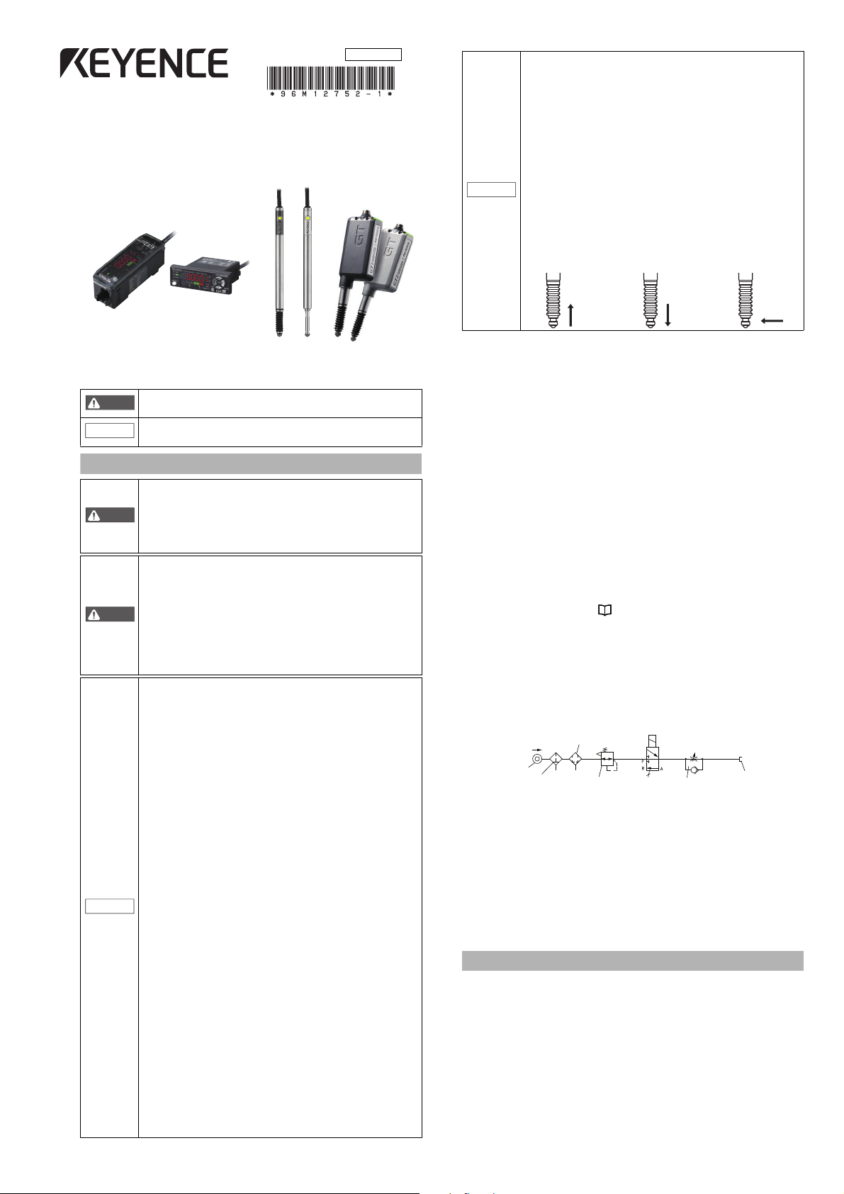
Mist separator
Air filter
Pressure
source
AIR
Solenoid
valve
Precision regulator
Air supply par t
Speed
controllerIllustration 1 - Pneumatic circuit
GT2-70
■
Symbols
The following symbols alert you to matters concerning the prevention of
human injury and product damage. Be sure to read these messages carefully.
Safety Information for GT2-70 Series
Series Instruction Manual
It indicates a hazardous situation which, if not avoided,
could result in death or serious injury.
It indicates a situation which, if not avoided, could result in
product damage as well as property damage.
If the following conditions are encountered, immediately turn
OFF the power. Continuing to use the GT2-70 Series under
these abnormal conditions may cause equipment failure.
• When water or foreign matter enters the controller
• When the GT2-70 Series is dropped or the housing is damaged
• When the GT2-70 Series produces smoke or an abnormal smell
• Do not use the GT2-70 Series with a voltage other than
specified voltage, as this may cause fire, electric shock
or equipment failure.
• Do not disassemble or modify the GT2-70 Series. This
may cause fire or electric shock.
• Do not use this product for the purpose to protect a
human body or a part of human body.
• This product is not intended for use as explosion-proof
product. Do not use this product in a hazardous location
and/or potentially explosive atmosphere.
• Be sure to turn OFF the power of the GT2-70 Series and any
connected devices before connecting or disconnecting the
cables. Otherwise, there may be a risk of damage.
• Do not turn OFF the power while setting parameters.
Otherwise, the settings may be partially or completely lost.
• At startup and during operation, be sure to monitor the
function performance of the GT2-70 Series.
• Do not modify the GT2-70 Series or use it in any way
other than described in the specifications.
• The function performance of products used or modified
in this way cannot be guaranteed.
• When the GT2-70 Series is used in combination with other
instruments, function performance may be degraded,
depending on operating conditions and the surrounding
environment. Use the GT2-70 Series after fully studying
the effect of combined use with other instruments.
• Do not expose the GT2-70 Series and peripheral devices
to sudden temperature change. This may cause
condensation, damaging the equipment.
●
Environmental conditions
To use the GT2-70 Series properly and safely, do not
install the GT2-70 Series in the following locations. Use
of this equipment in an improper environment may
cause equipment failure.
•
Locations outside
•
Locations with high humidity, a large amount of dust,
or poor ventilation
•
Locations where the temperature rises excessively
due to direct sunlight, etc.
•
Locations near corrosive or flammable gas
•
Locations where the GT2-70 Series is directly
subjected to vibration or impact
•
Locations where water, oil or chemicals may come
into contact with the GT2-70 Series
•
Locations where static electricity may easily occur
●
Noise countermeasures
Installation near a source of electrical noise such as a
power source or a power cable may cause malfunction
or failure of the equipment. Adopt appropriate
countermeasures against noise by using a noise filter
or wiring cables in separate ducts, attaching insulation
to the amplifier or the sensor head, etc.
96M12752
●
Handling of the sensor head
•
The GT2-70 Series and peripheral devices are precision
machines. Do not drop, or cause any other impact to these
devices. Doing so may cause damage or malfunction.
•
Do not apply weight greater than what is listed below to the spindle.
Do not apply rotational torque. Otherwise the spindle may break.
•
The GT2-P12KL(F)/P12L(F)/PA12K/PA12 spindle can rotate a
maximum of about 4.5°. When using an offset contact (OP-
77683) or similar, if pressure in the rotational direction is
applied to the contact, the measurement position may change.
•
Although the GT2-PA12K/PA12/H12K/H12KF/H12/H12F/
H32/H50/A12K/A12/A32/A50 has a protection rating of
IP67, avoid using it immersed in water or in places where
liquid such as oil may come into contact with it.
•
Although the GT2-P12K(F)/P12(F) has a protection rating of
IP67G/NEMA Type 13, some types of oil may damage the device.
•
If dust, metal powder, or similar becomes attached to the sliding part
of the sensor head, mechanical responses may become slow. If this
happens, replace the dust seal with a replacement dust seal (OP-
87932). Refer to the instruction manual included with the replacement
dust seal (OP-87932) for instructions on how to replace the dust seal.
■
Other precautions
●
Effects of surrounding air temperature
To use the GT2-70 Series with high accuracy, do not use the GT2-70 Series in
an environment in which the surrounding air temperature changes sharply.
It will take about 40 minutes for the 12 mm type, and 60 minutes for the 32 mm/50 mm type for
the internal temperature to stabilize when the surrounding air temperature has changed by 10°C.
●
Warming up
The circuit is not stable immediately after the power turns ON, which
sometimes causes the indicated value to gradually fluctuate. Wait for about
5 minutes when using the 12 mm type and about 10 minutes when using
the 32/50 mm type after the power turns on before starting operation.
●
GT2-PA12K/PA12 (See illustration 1 for the pneumatic circuit)
•
This model uses a single-acting cylinder. The internal spring will
return the sensor head to its home position.
•
The air supply hole cannot be removed.
•
Use an air filter, mist separator, etc. to provide clean dry air. Empty the
drainage from the filter regularly, before it exceeds the specified line.
•
Before connecting the air tube to the air supply hole, be sure to blow
plenty of air through the pipes (flushing) to remove any foreign matter.
•
Make sure that the air pressure of the supplied air is constant and in the range
of 0.24 to 0.26 MPa. Use a precision regulator to control the air pressure. If
the air pressure is below 0.24 MPa, the spindle may not extend fully.
•
When supplying air (with the spindle extended), up to 3L/min of air
will be emitted from the tip of the dust seal.
•
The measuring ability of the device changes according to the air pressure
of the air supply. Refer to "Specifications" (page 14) for details.
●
GT2-A12K(L)/A12(L)/A32/A50 (See illustration 1 for the pneumatic circuit)
•
This model uses a single-acting cylinder. The internal spring will return the sensor head to
its home position when air pressure is removed. DO NOT supply air to the exhaust valve.
•
The air cylinder cannot be removed.
•
Use the regulator to supply the stable air pressure to the sensor head.
•
Use the air filter and mist separators to supply dry air. Empty the
drainage from the filter regularly, before it exceeds the specified line.
•
Make sure that the air pressure of the supplied air is constant and
in the range of 0.25 MPa to 0.5 MPa.
•
The coupling socket and the exhaust valve that are supplied with the
air cylinder are dedicated for this product. They cannot be removed.
●
Power suppl y
•
Noise superimposed on the power supply may cause malfunction. Be sure to
use the DC stabilized power supply provided with an insulation transformer.
•
In the case of a commercially available switching regulator, be sure to
ground the frame ground terminal or the ground terminal.
●
About dust boot
When the dust boot of the sensor head is damaged, use an optional dust boot sold
separately (For GT2-P12K(F)/P12(F)/H12K(F)/H12(F)/A12K/A12: OP-84332 (Material: NBR
(attached when shipped)). For GT2-P12K(F)/P12(F): OP-87859 (Material: Fluororubber).
For GT2-H32/A32: OP-84459 (Material: NBR (attached when shipped)). For GT2H50/A50 (Material: NBR (attached when shipped)).) Attach the dust boot correctly.
The dust boot may deteriorate, depending on the environment it is
used in. In this case, replace the dust boot regularly.
* Do not use the dust boot on the GT2-P12KL/P12L/PA12K/PA12/H12KL(F)/H12L(F)/H32L.
Precautions on Regulations and Standards
■
CE Marking
●
EMC Directive (2004/108/EC)
•
Applicable standard EMI: EN61326-1, Class A
•
This product is designed for use in industrial environments.
Remarks: This specification does not give any guarantee that the end-product
with this product incorporated complies with the essential requirements of
EMC Directive. The manufacturer of the end-product is solely responsible for
the compliance on the end-product itself according to EMC Directive.
■
UL Certificate
UL File No. E120439 (Category: NRNT2/NRNT8)
•
Use the power supply with Class 2 output defined in NFPA70
(NEC: National Electrical Code).
•
GT2 series are evaluated as open type devices. These products
can not be a part of an enclosure.
1
EMS: EN61326-1
GT2-70-M-E
Page 2

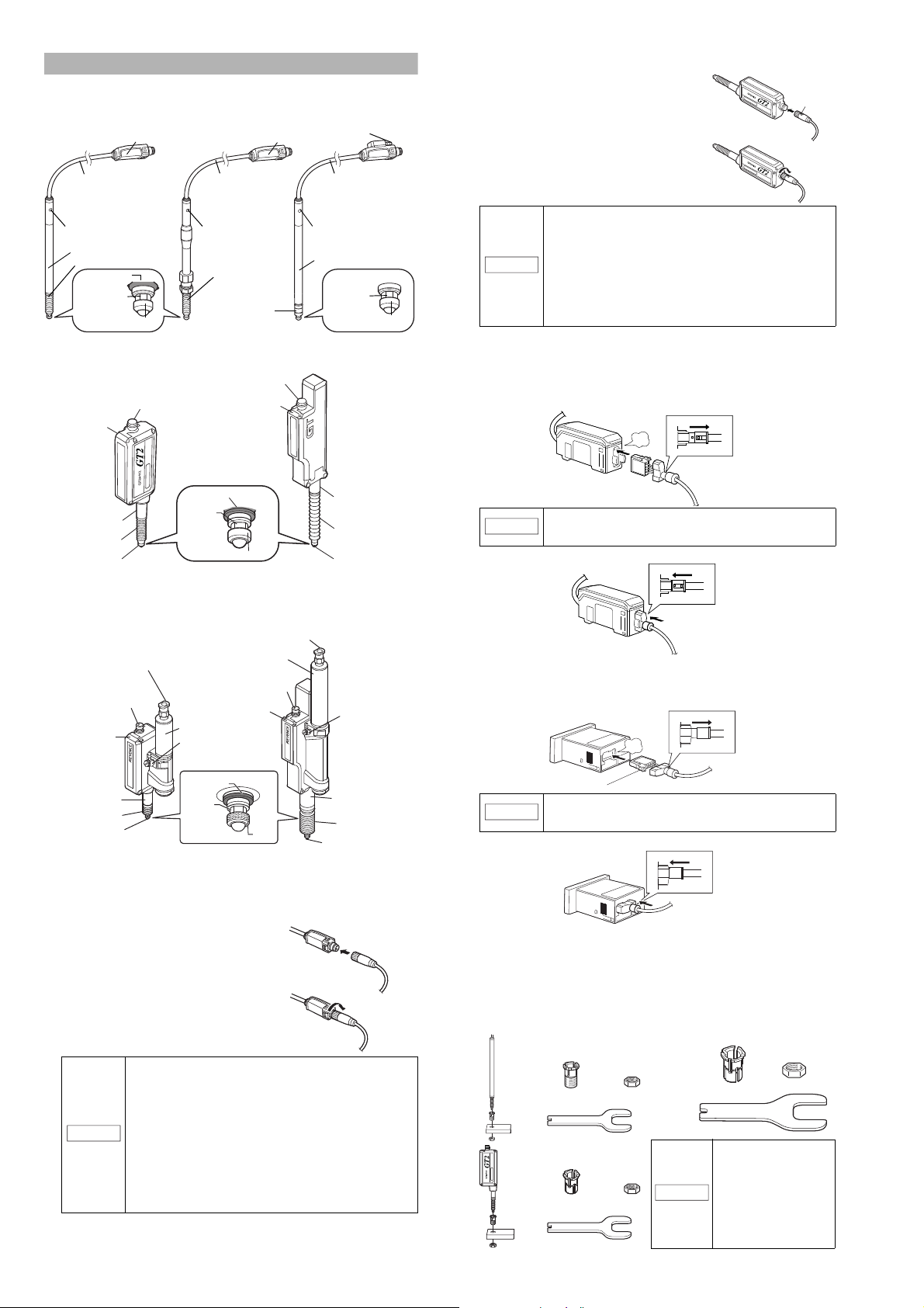
Package Contents
MODE
SE
T
SET
HI
P-H
B-H
P-P
CALC
GO
LO
1
2
3
HI
PV
SERIES
P
R
E
S
E
T
L
O
TIM
GT2-71N/71P/71CN/71CP (Main unit)
GT2-71MCN/71MCP (Main unit analog output)
MODE
S
E
T
SET
HI
P-H
B-H
P-P
CALC
GO
LO
1
2
3
HI
PV
SERIES
P
R
E
S
E
T
L
O
TIM
GT2-72N/72P/72CN/72CP
(Expansion unit)
Amplifier x 1
Head connector label x 1
*Used for the calculation only mode.
Amplifier x 1
Instruction manual x 1
Amplifier x 1
GT2-71D (Pulse output)
Instruction manual x 1
Switch cover label x 1
GT2-CA2M/CA10M
GT2-75N/75P (Main unit)
Amplifier x 1
Power cable (2 m) x 1
(Number of conductors: 12)
Front protective cover x 1
Instruction manual x 1
Panel mounting bracket x 1
GT2-76N/76P (Expansion unit)
Amplifier x 1
Panel mounting bracket x 1
Front protective cover x 1
I/O cable (2 m) x 1
(Number of conductors: 10)
Expansion cable (50 mm) x 1
P
RE
S
E
T
TIM
HI
HI
P‑H
B‑H
P‑P
CALC
LO
GO
LO
RV
1
2
3
PRESET
TIM
HI
HI
P
‑
H
B
‑
H
P
‑
P
CALC
LO
GO
LO
RV
1
2
3
Head connector label x 1
*Used for the calculation only mode.
GT2-P12K/P12
GT2-H12KF/H12F
GT2-H12KLF/H12LF
GT2-P12KL/P12L GT2-PA12K/PA12GT2-P12KF/P12F
Nut x 1
Key spanner x 1
GT2-H12K/H12
GT2-H12KL/H12L
Sensor head x 1 Sensor head x 1
Precautions on Handling x 1 Precautions on Handling x 1
GT2-A12KL/A12L
Sensor head x 1
Precautions on Handling x 1
GT2-H32 GT2-H32L
Sensor head x 1 Sensor head x 1
Precautions on Handling x 1 Precautions on Handling x 1
GT2-A12K/A12
Sensor head x 1
Precautions on Handling x 1
Sensor head x 1 Sensor head x 1
Precautions on Handling x 1 Precautions on Handling x 1
Sensor head x 1
Precautions on Handling x 1
Nut x 1
Key spanner x 1
Sensor head x 1
Precautions on Handling x 1
Nut x 1
Key spanner x 1
Sensor head x 1
Precautions on Handling x 1
Sensor head x 1
Precautions on Handling x 1
GT2-A32
Sensor head x 1
Precautions on Handling x 1
GT2-H50
Sensor head x 1
Precautions on Handling x 1
GT2-A50
Sensor head x 1
Precautions on Handling x 1
(1)
(2)
(3)
Fixture: OP-76877
Main unit
Connector
Expansion unit
End unit
End unit
The product package of each model should include the following items.
Check that all items are included before use.
■
Amplifier parts
●
DIN rail mount type
●
Amplifier connection cable
Use for connector type amplifiers (GT2-71CN/71CP/72CN/72CP/
71MCN/71MCP).
●
Panel mount type
●
Sensor head connection cable
GT2-CH2M/5M/10M/20M
(M8 straight connector)
NOTICE
We have taken all possible precautions in packaging; however, if
any parts are found to be defective or broken, please contact your
GT2-CHL2M/5M/10M/20M
(M8 L-shaped connector)
• The M8 L-shaped connector type cable cannot be
used with the GT2-H32(L)/H50/A32/A50.
• When a protection rating of IP67G and NEMA Type 13
enclosure is required for GT2-P12K(F)/P12(F), or a
protection rating of IP67G is required for GT2-PA12K/
GT2-PA12 use an M8 oil-resistant straight connector
type cable. Other cables do not meet the IP67G
protection rating or NEMA Type 13 enclosure rating.
GT2-CHP2M/5M/10M
(M8 oil-resistant straight connector)
nearest KEYENCE sales office.
Mounting the Amplifier and Wiring
■
Mounting the amplifier
●
DIN rail mount type (Main unit)
This section describes how to mount the DIN rail mount type:
(Main unit: GT2-71(C)N/71(C)P/71MCN/71MCP)
1
Fit the tab of the lower par t of the main unit to
the DIN rail. While inserting the main unit in
the direction of Arrow (1), push the body
down in the direction of Arrow (2).
2
To detach the amplifier, while pushing the main unit in the direction
of Arrow (1), pull the body up in the direction of Arrow (3).
When using a fixture (Optional item: OP-76877), mount as shown below.
■
Sensor head parts
●
Sensor head
GT2-70-M-E
●
DIN rail mount type (Expansion unit)
This section describes how to mount the DIN rail mount type
(Expansion unit: GT2-72N/72P/72CN/72CP).
The expansion unit can only be used in addition to the main unit.
Up to 14 expansion units can be added to one main unit.
• When adding an amplifier (expansion unit), be sure
the power of both main and expansion units is OFF
before operation. Mounting when the power is ON
may damage the equipment.
• Be sure to completely connect an expansion unit to a
main unit. Oblique or improper connections may
damage the equipment.
• When connecting expansion units, some of the
NOTICE
1
Detach the expansion cover of the main unit.
2
Mount the expansion unit to be added to the DIN rail.
specifications are restricted depending on the
number of units to be connected. Refer to page 14,
"Specifications" for details for details.
• An expansion unit of different output type cannot be
added (for example, an expansion unit of NPN output
cannot be added to a main unit of PNP output).
• No expansion unit can be connected to the pulse
output type (GT2-71D).
• An expansion unit of the DIN rail mount type cannot
be added to a main unit of the panel mount type.
Main unit
Expansion cover
Refer to above, "DIN rail mount type", for details about how to mount.
3
Push and fix the expansion unit to the connector of the main unit until it clicks.
4
Mount the end units (OP-26751: a set of two pieces) sold
separately on both sides of the amplifiers (the main unit and
the expansion unit), then fix the end units with screws on the
upper part of each end unit (2 points x 2 units).
The mounting method of the end unit is the same as that of the amplifier.
2
Page 3

●
69.5 min.
21
45
+0.4
-0
Panel cut dimension
X=24 x (Number of amplifiers -1)+21
Panel thickness of mounting area
1 to 6 mm
(unit: mm)
X
45
Front protective cover
Amplifier
Panel
Panel mounting bracket
Tab
Expansion cable
Expansion
cable
Reference
Power cable
(When connecting the power cable)
click
Brown
Blue
Black
White
Gray
Orange
Green
Pink
Violet
Pink/Violet
Ye l l ow
Red
* Available only on the GT2-72CN/72CP (Quick disconnect type).
Not connected *
Not connected *
HIGH output
LOW output
GO output
HH output
LL output
PRESET input
BANK A input
TIMING input
BANK B input
RESET input
Panel mount type (Main unit)
This section describes how to mount the panel mount type:
GT2-75N/75P (Main unit).
1
Create a panel opening for mounting referring to the dimensions below.
2
Insert the main unit, back end first, into the opening of the panel.
3
Insert the panel mounting bracket in the direction shown below into the main
unit from the back, then fit the front protective cover to the main unit face.
To detach the panel mounting bracket, pull it while
pushing apart the tabs provided on its both ends.
●
Panel mount type (Expansion unit)
This section describes how to mount the panel mount type:
GT2-76N/76P (Expansion unit).
The expansion unit can only be used in addition to the main unit.
Up to 14 expansion units can be added to one main unit.
• Turn OFF the power before connecting the expansion
cable. Inserting or pulling the cable when the power
is turned ON may damage the equipment.
• Be sure to completely connect the expansion cable.
Oblique or improper connections may damage the
equipment.
• When connecting expansion units, some of the
NOTICE
1
Create panel openings for mounting according to the number of
specifications are restricted depending on the
number of units to be connected. Refer to Page 14,
"
Specifications
• An expansion unit of different output type cannot be
added (for example, an expansion unit of NPN output
cannot be added to a main unit of PNP output).
• An expansion unit of the panel mounting type cannot
be added to a main unit of the DIN rail mounting type.
expansion units to be mounted (the expansion unit to be added).
Refer to above, "Panel mount type (Main unit)", for details about
panel cut dimensions.
2
Mount the amplifier (the expansion unit to be added) to the panel.
Refer to above "Panel mount type (Main unit)", for details about how
to mount.
3
Connect the amplifiers (the main unit and the expansion unit) with an
expansion cable.
When installing the amplifier side by side, the 300 mm
NOTICE
expansion cable (OP-35361) is required. If using even
one 300 mm expansion cable, the number of expansion
units is limited to four.
" for details.
■
Wiring of amplifier
NOTICE
●
How to connect the power cable to the DIN-mount quick disconnect type
Insulate unused I/O wires individually.
Quick disconnect type amplifiers must be connected with the power
cable (I/O cable) GT2-CA2M/CA10M (sold separately).
click
Connect the cables with
the white points aligned
(When connecting the power cable) (When disconnecting the power cable)
●
How to connect the power cable to the panel mount type
The accessory power cable (I/O cable) must be connected to the
amplifier of the panel mount type.
(When disconnecting the power cable)
• The number of power (I/O cable) conductors is different
between the main unit and the expansion unit (Main unit:
12 conductors, Expansion unit: 10 conductors).
• The power of the expansion unit is supplied through the
expansion cable being connected to the main unit.
●
Power cable (I/O cable)
The following illustrates the power cable (I/O cable) (also applicable
to the panel mount type).
Refer to Page 15 of this manual for details about I/O circuits.
GT2-71N/71P/71CN/71CP (Main unit)
Brown
Blue
Black
White
Gray
Orange
Green
Pink
Violet
Pink/Violet
Ye l l ow
Red
* Supply 20-30V DC power when using expansion units.
10-30 V *
HIGH output
LOW output
GO output
HH output
LL output
PRESET input
BANK A input
TIMING input
BANK B input
RESET input
GT2-72N/72P/72CN/72CP (Expansion unit)
GT2-71MCN/71MCP (Analog output)
Brown
Blue
Black
White
Gray
Orange
Green
Pink
Violet
Pink/Violet
Ye l l ow
Red
20-30 V
HIGH output
LOW output
GO output
Analog output
Analog GND
PRESET input
BANK A input
TIMING input
BANK B input
RESET input
GT2-71D (Pulse output)
Brown
Blue
Black
White
Orange
Violet
Gray
Green
Pink
10-30 V
A phase
B phase
Z phase
A phase
B phase
Z phase
Current position returning input
3
GT2-70-M-E
Page 4
Connecting and Mounting the Sensor Head
NOTICE
Operation indicator
Relay connector
Cable
connector
Dust boot
Mounting fixture
Dust boot
※
Spindle
Contact
Dust boot
●
GT2-P12K(L)/P12(L)
●
GT2-P12KF/P12F
Cable between
the sensor
head and relay
connector
●
GT2-PA12K/PA12
Relay connector
Cable
connector
Cable
connector
Cable
between the
sensor head
and relay
connector
Operation indicator
Cable between
the sensor
head and relay
connector
Mounting fixt ure
Operation indicator
Contact
Spindle
Air supply hole
Dust seal
NOTICE
Arrow
Unlocked
Click
Lock cover
Locked
Lock cover
Orient the connector so that the lock lever is at the left side.
Unlocked
Lock cover
Click
Locked
Lock cover
Tightening sleeve
Key wrench
Nut
Optional head mounting
bracket D (OP-84327)
●
GT2-P12K(L)/P12(L)/PA12K/PA12/
H12K(L)/H12(L)/A12K(L)/A12(L)
●
GT2-H32(L)/H50/A32/A50
NOTICE
When mounting the GT2H32L facing upward, be
sure to use the mounting
holes on the side of the
sensor head. If the
sensor head is mounted
using head mounting
bracket D, the spindle
may not fully extend.
Mounting
illustration
■
Names of parts of the sensor head
* Not included in the GT2-P12KL/P12L.
●
GT2-H12K(L)(F)(LF)/H12(L)(F)(LF)/H32(L)/H50
Cable connector
Head indicator
Cable connector
Head indicator
●
For units other than GT2-P***/PA***
1
Insert the sensor head connection
cable into the cable connector of the
sensor head.
2
Secure the connector by rotating the
grooved portion.
• When connecting the connector, be sure to insert it
straight, and tighten it securely. (Recommended
tightening torque: 0.4 to 0.5 N·m*)
If the connection is not tight enough, the connector
may be loosened by vibration or other causes,
leading to a connection failure.
(* After tightening it firmly by hand, use pliers or other
tools to rotate it about 30
• The M8 L-shaped connector (GT2-CHL*M) cannot be
used with the GT2-H32(L)/H50/A32/A50.
o
for further tightening.)
To disconnect the sensor head connection cable, reverse the steps above.
■
Connecting the amplifier
●
DIN rail mount type
1
Remove the lock cover of the connector of the sensor head
connection cable, and insert the sensor head connection cable
into the connector on the side of the amplifier until it clicks.
Dust boot
mounting fastener*
*1 A mounting bracket is attached to
GT2-H12KF/H12F/H12KLF/H12LF.
*2 Not included in the GT2-H12KL/H12L/H12KLF/H12LF.
●
GT2-A12K(L)/A12(L)/A32/A50
Head indicator
Mounting fixture
Dust boot*
* Not included in the GT2-A12KL/A12L.
■
Connecting the sensor head connection cable
●
For GT2-P***/PA***
1
Insert the sensor head connection cable
1
2
Dust boot*
Contact
Coupling socket
Cable connector
Contact
Spindle
Head indicator
Air cylinder
Exhaust valve
Dust boot
Spindle
Contact
*3 Not included in the GT2-H32L.
Coupling socket
Air cylinder
Cable connector
Contact
Contact
into the cable connector on the relay
connector cable.
2
Secure the connector with the sensor
head connection cable screw.
mounting fastener
3
Dust boot*
Contact
Exhaust valve
Mounting fixture
Dust boot
To disconnect the sensor head connection cable,
NOTICE
2
Put the lock cover on the connector, and lock the lock cover.
●
Panel mount type
1
Remove the lock cover of the connector of the sensor head
connection cable, and insert the sensor head connection cable into
the connector on the back of the amplifier until it clicks.
NOTICE
2
Put the lock cover on the connector, and lock the lock cover.
■
Mounting the sensor head
●
Mounting directly to the jig
Before mounting the sensor head directory to the jig, create a hole in the
jig. Attach the sensor head using the optional head mounting bracket
sold separately. A mounting bracket is provided with the GT2-P12KF/
P12F/H12K(L)F/H12(L)F as standard. Attach it with the supplied nut.
press and hold the lock lever on the side of the
connecter and disconnect the cable.
To disconnect the sensor head connection cable,
press and hold the lock lever on the side of the
connecter and disconnect the cable.
GT2-70-M-E
•W
hen connecting the connector, be sure to insert it
straight, and tighten it securely. (Recommended
tightening torque: 0.4 to 0.5 N•m*)
If the connection is not tight enough, the connector
may be loosened by vibration or other causes,
leading to a connection failure.
(* After tightening it firmly by hand, use pliers or other
tools to rotate it about 30° for further tightening.)
• When the head is attached to a moving part, and the
cable will be repeatedly bent, ensure that the cable
between the sensor head and relay connector does
not bend. Instead, bend the sensor head cable
connecting the relay connector and the amplifier.
Optional head mounting
bracket A (OP-76874)
Tightening sleeve
Key wrench
Optional head mounting
bracket C (OP-84396)
Tightening sleeve
Key wrench
Nut
Nut
4
Page 5
1
φ10
+0.005
+0.1
0.5 × 45°
recession
5.5 〜11
Nut
mounting
side
Sensor head
insertion side
(Unit: mm)
●
GT2-P12K(L)/P12(L)/PA12K/PA12/
H12K(L)/H12(L)/A1K2(L)/A12(L)
●
GT2-H32(L)/H50/A32/A50
●
GT2-P12KF/P12F/H12K(L)F/H12(L)F
Sensor head
Chamfered side
Nut
Key wrench
Dust boot
Wrench
8.5
8
+
0
.
2
0
0
+
0
.
0
0
5
M
4
x
0
.
7
Make sure that the metal plating
mounting bracket F attaches to is made
of SUS (SUS303 reco mmended) and is
at least 5 mm thick.
•
GT2-P12K(L)/P12(L)/PA12K/PA12
Mounting illustration
Nut
Wrench
Dust boot
Cut the jig to create a sensor head mounting hole referring to the
illustration below.
3
Align mounting bracket F with the hole made in step 1 and secure it
using the supplied hexagonal wrench.
*2
0.5 to 1.0
±1°
45°
Tightening
sleeve
*1
+0.027
+0.005
( )
φ10 G8
*1 For head mounting bracket C *2 Processing accuracy : ±0.05
+0.1
φ10
+0.005
2
Insert the tightening sleeve into the hole (from the Chamfered side),
insertion
side
φ0.025
A
Nut
mounting
side
5.5 to 11.3
A
(Unit: mm)
+0.1
+0.006
φ14
*2
45°
Tightening
sleeve
insertion
side
φ0.025
0.5 to 1.0
±1°
A
and loosely tighten with the nut.
Tightening sleeve
Nut
In the illustration on the left above, if the nut is fully
NOTICE
3
Insert the sensor head in the tightening sleeve. While securing the tightening
tightened when the sensor head is not yet inserted, the
fixture will become deformed.
Chamfered side
sleeve with the included key wrench, tighten the nut with a separate wrench.
A
Nut
mounting
side
5.5 to 11.3
(Unit: mm)
*2
*2
4
Insert the sensor head, and tighten the screw loosened in step
2 using the supplied hexagonal wrench to secure. The
recommended tightening torque is 0.6 to 0.8 N•m. Make sure
that the dust boot does not obstruct the metal plating that
mounting bracket F is attached to.
• Make sure that the dust boot does not become
damaged during the procedure.
• When loosening the screw with the hexagonal wrench,
NOTICE
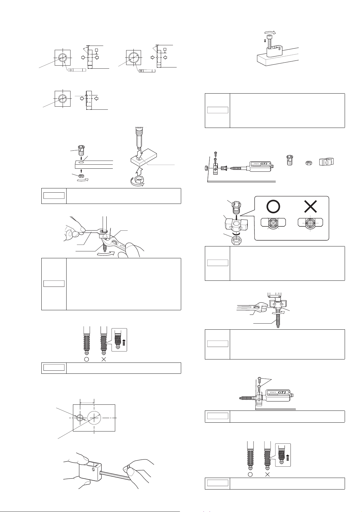
●
Mounting on the side of a surface
When mounting to the side of a GT2-P12K(L)/P12(L)/PA12K/PA12/H12K(L)/H12(L)/
A12K(L)/A12(L) unit, use the optional head mounting bracket B (OP-76875).
1
Insert the tightening sleeve into the mounting bracket from the side
insert the long end of the hexagonal wrench into the
hex screw and rotate the small end with your hand.
• Do not forcibly tighten the hex screw.
• Cannot be used with GT2-P12KF/P12F/H***/A***.
Optional head mounting bracket B
(OP-76875)
Tightening sleeve Nut Mounting bracket
with a depression, and loosely tighten with the nut.
Tightening sleeve
Mounting bracket
Tightening the nut while fixing the sensor head may
lead to damage.
• The tightening torque for mounting bracket A (OP-76874),
mounting bracket C (OP-84396), and the nuts supplied with
GT2-H12K(L)F/H12(L)F/P12KF/P12F is between 5 and 7 N•m
NOTICE
4
Rotate the dust boot so that the side line is straight. (Models other
than GT2-PA12K/PA12)
Check with the spindle pushed in.
NOTICE
●
Using mounting bracket F
1
Refer to the illustration below and cut the jig to create a sensor head
mounting hole.
(the recommended tightening torque is 5 N•m). Apply
tightening torque between 15 and 18 N•m (20 to 23 N•m
when using the GT2-A32/A50) to head mounting bracket D
(OP-84327). Use the wrench that matches the nut width.
• Care must be taken not to damage the dust boot
when tightening.
If the dust boot is not straight, it becomes easier to
damage when the spindle is moved.
Nut
• If the sleeve is inserted from the wrong side, the
sensor head cannot be secured.
• Strongly tightening the nut without the sensor head
NOTICE
2
Insert the sensor head into the tightening sleeve, and tighten
inserted may deform the tightening nut.
• Head mounting bracket B cannot be used in
combination with head mounting bracket C (OP-
84396) or head mounting bracket D (OP-84327).
Notice the correct angle of the tightening sleeve.
the nut with a wrench.
Tightening the nut while fixing the sensor head may
lead to damage.
NOTICE
3
Secure the sensor head with M4 screws.
Mount the sensor head with the model label on top. For GT2-P12K (L)/
P12 (L)/PA12K /PA12, mount so that the head indicator is on top.
• Apply a tightening torque of 5 to 7 N•m (the
recommended tightening torque is 5 N•m).
Use the wrench that fits the width of the nut.
• Care must be taken not to damage the dust boot when tightening.
M4 screws
2
Loosen the screw on the side of mounting bracket F using the
supplied hexagonal wrench.
NOTICE
4
Rotate the dust boot so that the side line is straight. (Models other
than GT2-PA12K/PA12)
• Never apply tightening torque over 1.4 N•m.
• Care must be taken not to damage the dust boot when tightening.
Check with the spindle pushed in.
NOTICE
If the dust boot is not straight, it becomes easier to
damage when the spindle is moved.
5
GT2-70-M-E
Page 6

●
NOTICE
NOTICE
NOTICE
NOTICE
Mounting illustration
M4 tap
23 ± 0.15 mm
M4 screws (Mounting hole dimensions)
Air tube
Air supply hole
Relay connector
Relay connector
Air tube
Air tube
Coupling socket
Tube end
Reference
NOTICE
Screw
Air tube
Air tube
Exhaust valve
Spindle
Contact
Key wrench
Pliers
Cover the contact
with a cloth
Mounting to the mounting holes
The mounting holes on the side of the GT2-H32(L)/H50/A32/A50
unit can be used to install to the side of a table or other surface.
Detaching the air tube
•
To detach the air tube, (1) press down on the release ring, (2) pull out the tube.
(2)
• Roughness of the mounting surface may cause the
sensor to tilt, and sufficient accuracy may not be
obtained. When performing a high-accuracy
measurement, use a jig to mount the sensor head.
"
• Apply tightening torque between 1.2 and 1.5 N•m.
■
Installing the Air Tube
●
Compatible air tube
Mounting directly to the jig
" (page 4)
Use a tube with the following specifications.
Item Description
Recommended tubing material Urethane
Tubing size
●
How to Attach/Detach the Air Tube (GT2-PA12K/PA12)
Attaching the air tube
•
Insert the air tube into the air supply hole on the relay connector.
Detaching the air tube
•
Outer diameter
Inner diameter
• For best results, cut the end of the tube at a right angle,
and ensure that the outer perimeter is not damaged,
and that it still maintains a circular cross section.
• If the tube is not properly inserted, air leakage may result.
• After attaching, pull on the tube to make sure it is secure.
• Use a urethane tube. Make sure it also has a bending
radius of at least 50 mm.
4 mm
2.5 mm
To detach the air tube, pull the air tube in the direction of the arrow,
as indicated in the figure below.
(1)
• Before detaching the tube, be sure to stop any air flow.
NOTICE
●
For GT2-A12K/A12/A32/A50 when an IP67 enclosure rating is required
To maintain an IP67 enclosure rating, the following must be satisfied:
•
Firmly connect tubing with 2.5 mm inner diameter to the exhaust
port until it bottoms out.
Ensure that the tube end is free of dirt or water.
•
Tighten the screw of the exhaust valve with a torque of 0.5 to 0.6 N•m.
If the screw is loose, the IP67 rating cannot be guaranteed.
●
Adjustment of Spindle Movement Speed
To adjust the spindle movement speed, install a speed controller between
the cylinder and the air supply. Using OP-87970 is recommended.
NOTICE
• Press down on the release ring evenly from both sides, and
pull the tube out. Uneven pressure may result in damage to
the tube or damage to the operation of the air cylinder.
By loosening the screw of the exhaust valve, you can
change the exhaust port angle.
Speed controller
Adjusting the speed.
•
To further decrease spindle movement speed, use a coil-shaped
tube (OP-87986) or similar to increase the distance between the air
supply hole and the speed controller
•
The speed controller will not operate if installed in the reverse direction
Release ring
Air supply
Indication symbol
.
.
●
How to Attach/Detach the Air Tube (GT2-A12K(L)/A12(L)/A32/A50)
Attaching the air tube
•
Feed the tubing into the socket until it bottoms out (about 1/2").
The socket will ensure a tight seal around the tubing.
GT2-70-M-E
Before detaching the tube, be sure to stop any air flow.
• For best results, cut the end of the tube at a right
angle, ensure that the outer perimeter is not damaged,
and that it still maintains a circular cross section.
• If the tube is not properly inserted, air leakage may
result (see figure below).
• After attachment, pull on the tube to make sure it is secure.
Contact
This section describes how to replace the contact, and how to mount
the lift lever.
•
Detach the sensor head from the device or fixture (metal plating,
etc.) before replacing the contact
•
When applying pliers to the contact, be sure not to rotate the main
part and cover the contact with a cloth
•
Never apply tightening torque over 0.2 N•m when attaching a contact
Fix the roller contact (OP-77680) or the offset contact (OP-77683)
•
with the fixing nut in the same direction as in actual use
Applying an adhesive, a thread locking agent, is recommended to
•
prevent the nut from getting loose
Position the roller contact carefully in the proper direction. Care
•
must be taken not to apply misdirected force to the shaft
■
How to replace the contact
While securing the spindle with the accessory key wrench, detach the
contact with pliers. Then attach a new contact.
.
.
.
How to replace the dust seal
Refer to the instruction manual included with the replacement dust seal
(OP-87932).
6
.
.
.
Page 7

■
Reference
GT2-71
GT2-71
Detection level
indicator
[PRESET]
button
Status indicator Arrow buttons
PV indicator
Preset indicator
HIGH position indicator/
LOW position indicator
Digital LED display
[MODE] button
Bar LEDs
Bank indicator [SET] button
Special output indicator
Timing input
indicator
1. P.V. value display
2. Calculated value display*
1
3. R.V. value display
8. Preset value setup display
7. LL setting value display
while using 5-output function*
2
4. HH setting value display
while using 5-output function*
2
6. LOW setting value display
5. HIGH setting value display
Master workpiece
HIGH setting value display
HIGH setting value
LOW setting value
Tolerance tuning setting range
This is a method for setting a range based on
the detection value of a master workpiece
when the master workpiece is available.
How to mount the lift lever
Mount the lift lever (OP-84397) between the spindle and the contact.
Secure the spindle with the lift lever and attach/detach the contact.
Amplifier display
■
Names of parts of the amplifier
For details about the GT2-71D (pulse output type) amplifier,
refer to "
■
Digital LED display
The main display during detection can be switched to the displays
as shown below by pressing the left/right Arrow buttons.
Refer to "Detection Functions" in the "GT2-70 Series User's
Manual" for details about the setting mode screen in which various
settings are performed.
GT2-71D (pulse output type)
" (page 13).
■
Setup using buttons
1
Set any main display and perform the
detection of the detection target (master
workpiece) to serve as a reference for zeropoint correction.
2
Press the [PRESET] button (white button) with the master workpiece
being detected.
After "PrESEt" has blinked several times on the digital LED display
of the amplifier, "0.000.0"* will appear.
The zero-correction is completed.
* When the preset function is set, the preset value will appear.
■
Setup using external input (Pink wire)
1
Perform detection of the target (master workpiece) to serve as a
reference for zero-point correction.
2
Connect the pink wire to the appropriate terminal.
Refer to page 15 of this manual for details about external input circuit diagrams.
Setup of Limit Values
The limit values are an upper limit value (HIGH setting value) and a
lower limit value (LOW setting value). Setting these values enables
three types of judgment (display/output): above the upper limit (HIGH),
below the lower limit (LOW), and within the range (GO).
■
Manual setup of limit values
The following shows how to set manually an upper limit value (HIGH
setting value) and a lower limit value (LOW setting value).
1
When in the main display, press the left/
right Arrow buttons until the HIGH
setting value display appears.
2
Enter an upper limit value (HIGH setting
value) with the top/bottom Arrow buttons.
3
Press the right Arrow button to display the
LOW setting value display.
4
Enter a lower limit value (LOW setting
value) with the top/bottom Arrow buttons.
The setup of range criteria values is
completed.
To return to the P.V. value display, press the left/right Arrow buttons.
LOW setting value display
Tips for Convenient Functions
■
Automatic setup of limit values
This function automatically sets an upper limit value (HIGH setting
value) and a lower limit value (LOW setting value).
For master workpieces, set by "tolerance tuning"; and for actual
works (good or defective), set by "two-point tuning".
●
Tolerance tuning
*1 This display appears only while the calculation function is used
and an expansion unit is connected.
*2 • This display appears only when [5out] is selected for [16.
Special output setting] in the basic setting mode.
• This display does not appear on GT2-71MCN/71MCP.
1. P.V. value display ([P.V. = Present Value] Criterion value display)
Displays a value to be used for output judgment.
2. Calculated value display
Displays a calculated value such as a maximum or minimum value
of several detection points created when adding an expansion
unit(s) (Displayed only when an expansion unit(s) is added).
3. R.V. value display ([R.V. = Raw Value] Raw value display)
Displays an actual detection value of the detection target.
4. HH setting value display while using 5-output function
Displays/Sets the setting value to set above the HIGH setting value.
5. HIGH setting value display
Displays/Sets an upper limit value of the range of the detection target.
6. LOW setting value display
Displays/Sets a lower limit value of the
7. LL setting value display while using 5-output function
Displays/Sets the setting value to set below the LOW setting value.
8. Preset value setup display
Displays/Sets an arbitrary value to be added to or subtracted from
the display value.
Zero-Point Correction
When you use this equipment for the first time or after the sensor head
is changed, be sure to correct the reference zero point.
Reference
• When "------" is displayed, zero-point correction is disabled.
• Zero-point correction can be performed approx. 1 million
times. When zero-point calibration is frequently used, you
can perform setting so that the zero-point calibration will not
be written into the memor y. Refer to "Origin Alignment" in the
"GT2-70 Series User's Manual" for details.
range
of the detection target.
Reference
1
When in the main display, press the left/
right Arrow buttons until the P.V. value
display appears, then perform detection of
the master workpiece.
Reference
2
Press the [SET] button while the master workpiece is being detected
to capture the detected value.
3
Press the upper/bottom Arrow buttons to enter a tolerance tuning
setting range.
4
Press the [SET] button to fix the tolerance tuning setting range.
After [SEt] blinks several times on the digital LED display of the
amplifier, the P.V. value display automatically appears.
Tolerance tuning is completed.
●
Two-point tuning
This is the method of setting the median values of the detected
good and/or defective workpieces as a range when the good
workpiece and HIGH/LOW defective workpieces are available.
Reference
1
When in the main display, press the left/
right Arrow buttons until the HIGH setting
value display appears.
When "------" is displayed, tolerance tuning is disabled.
When "-FFFF" or "FFFF" is displayed, the settings cannot
be set correctly.
Tolerance tuning is enabled only when in the P.V. value
display.
Two-point tuning is disabled when "------" is displayed as a
R.V. value. When "- FFFF" or "FFFF" is displayed, setting
cannot be done accurately.
HIGH setting value display
7
GT2-70-M-E
Page 8

2
Reference
Reference
Reference
Current output
Measurement value
Upper limit valueLower limit value
0
20mA
4mA
Reference
NOTICE
Reference
E
Full keylock display
E
E
3
4
5
6
■
■
■
■
■
■
GT2-70-M-E
Detect the good workpiece and press the [SET] button to capture the
detected value.
"SEt" and the detected value blink alternately, and the value of the
good workpiece is fixed.
Detect the HIGH defective workpiece and press the [SET] button to
capture the detected value.
The median value of this detected value and the one captured in step 2 blinks.
HIGH setting value is fixed.
Press the right Arrow button until the LOW
setting value display of the main display
appears.
Detect the good workpiece again and press the
LOW setting value display
[SET] button to capture the detected value.
Detect the LOW defective workpiece and press the [SET] button to
capture the detected value.
The median value of this detected value
and the one captured in step 5 blinks.
LOW setting value is fixed.
Two-point tuning is completed.
Press the left/right Arrow buttons to
return to the P.V. value display.
HIGH defective
workpiece
Good
workpiece
LOW defective
workpiece
HIGH
setting value
LOW
setting value
Preset
This function displays the value obtained by adding or subtracting a
preset value to or from the detected value.
By using this function and the zero point correction function together,
you can set an arbitrary value as a reference point of the work.
Refer to "Preset Function" in the "GT2-70 Series User's Manual" for
details about the preset function.
Bank switching
By using the bank function, the setting values of the HH side, HIGH
side, LOW side, LL side, preset point, and the preset value can be
registered up to four patterns.
The bank switching is useful when there are multiple detection targets
since the pre-registered settings (four patterns) can be easily switched.
Refer to "Bank Function" in the "GT2-70 Series User's Manual" for
details about the bank function.
Limit output function
This function can detect and output the mechanical movement of the spindle
on the contraction and extension sides. The stroke end of both sides can be
detected, so this function can be used for interlocking the device.
The limit output function cannot be used on GT2-71MCN/
71MCP (analog output type).
5-output
This function can increase the output levels to 5 levels: HH, HIGH,
GO, LOW, and LL. HH/LL can be set in the same way as HIGH/LOW.
Refer to "Setting 5-output" in the "GT2-70 Series User's Manual" for
details about the 5-output function.
The 5-output function cannot be used on GT2-71MCN/
71MCP (analog output type).
Analog output function
On GT2-71MCN/71MCP, the analog current (4 to 20 mA) is output
based on the measurement value (R.V.). The upper limit value and
the lower limit value can be set to a desired value.
Refer to "Analog Output Settings" in the "GT2-70 Series User's
Manual" for details about the analog output function.
The analog output function can only be used on GT271MCN/71MCP (analog output type).
Calculation with expansion unit
The GT2-70 Series can calculate various values using the detected
values of multiple detection points such as the maximum value or the
minimum value when an expansion unit(s) is added (up to 14 units).
Refer to pages 2 to 3 of this manual for details about how to add an
expansion unit.
The outline of the calculation function is shown below.
Calcu lation
No.
C1
C2
C3
C4
C5
function
Displays the maximum value of the values
Max.
of the main unit and expansion unit(s)
value
Displays the minimum value of the values
Min.
of the main unit and expansion unit(s)
value
Displays a difference between the maximum
value and the minimum value of the values
Flatness
of the main unit and expansion unit(s)
Displays the average obtained by dividing the
sum of the values of the main unit and expansion
Average
unit(s) by the number of units connected
Displays a difference obtained by
Reference
subtracting the display value of the main
difference
unit from that of each expansion unit(s)
Description
Number of units connecte d
Calculation
mode
Calculation
only mode
2 to 14 units
1 to 14 units
Not selectable
Calculation
No.
function
C6 Twist
C7
Warpage
C8
Thickness
●
Calculation mode
Description
Displays a degree of twist obtained from
the values of four detection points
Displays a degree of warpage obtained
from the values of three detection points
Displays a thickness obtained by
sandwiching the detection target between
the main unit and the expansion unit
Number of unit s connecte d
Calculat ion
3 units only 4 units only
2 units only 3 units only
1 unit only 2 units only
When "Calculation mode" is selected in "A1. Calculation mode", the main unit
outputs the calculation result, while the expansion unit does not. Only the head
indicator operates in the same way as the one on the main unit. (Except when
"C5. Reference difference" is selected for the calculation method)
Refer to "Calculation with expansion unit" in the "GT2-70 Series User's Manual"
for details about the calculation function.
●
Calculation only mode
When calculation only mode is selected in [A1. Calculation mode],
only the main unit outputs the calculation result, and the expansion
unit outputs the judgment according to each setting.
Refer to "Calculation with expansion unit" in the "GT2-70 Series
User's Manual" for details about calculation only mode.
■
Keylock
The calculation mode can be selected only on the main unit
with one or more expansion units connected.
• The calculation only mode is available only on the main
unit with two or more expansion units connected.
• When the calculation only mode is
selected, "C5. Reference difference"
cannot be selected for the
calculation method.
• When the calculation only mode is
selected, the sensor head cannot be
connected to the main unit. Attach
the included "head connector label"
to the head connector of the main unit.
The keylock allows you to avoid erroneous button operation during detection.
When the keylock is active, setup operations other than changing the display are disabled.
The keylock can be set on the main display only.
●
Set the keylock
When keylock is active, setup operations other than main display
switching and the [PRESET] button operation are disabled.
When in the main display, while pressing
the [MODE] button, press the upper Arrow
button for at least two seconds.
The keylock display will appear for several
seconds and then change to the main display.
MOD
+ (Press for at least two seconds)
●
Set full keylock
When full keylock is active, setup operations other than main display
switching are disabled.
Press the down Arrow button for at least two
seconds while pressing the [MODE] button in
the main display.
MOD
+ (Press for at least two seconds)
●
Cancel the keylock or full keylock
Press "up or down" Arrow button for at least
two seconds while pressing the [MODE] button
in the main display when the keylock is active.
The keylock cancel display will appear for several
seconds and then change to the main display.
MOD
+ or (Press for at least two seconds)
■
Initialize (Reset to the default state)
Reference
1
When in the main display, while pressing the
• Initialization can be set on the main display only.
• Initialization cannot cancel "span adjustment results".
• Refer to "Calibration" in the "GT2-70 Series User's Manual" for details
about how to set "Span adjustment" to the factory default state.
• During initialization, performing other steps than the following ones
stops initialization, and the display returns to the main display.
[MODE] button, press the [SET] button five times.
"rSt.no" will appear.
2
Press the top/bottom Arrow buttons to select "rSt.YES".
3
Press the [MODE] button.
"rSt.End" will appear.
Initialization is completed.
●
Default value list
Default values of function settings
Detection mode
Setting item Initial value
Hold update method
Response time
Timing type
Self timing level
Self timing delay type
User specified delay time
8
Calculation
mode
only mode
Keylock display
Keylock cancel display
Std
tim
100 (400)*
t-in
0.5000
Stb.d
t=1000
1
Page 9

Static hold delay stability criterion
GT2-71
Main screen
[MODE] button
MODE
Timing input
Hold update method
Regular update
Only available when either "P-H", "b-H", or "P-P" is selected in [ Detection mode].
Setting value
input screen
When "CAL.noH" is selected in
A1. Calculation mode setting.
Response time
MODE
When "nG-H" or "P-P" is selected
in 01. Detection mode.
External timing input
Rising edge
self-timing
Falling edge
self-timing
Timing type
MODE
Only available when either "Std", "P-H", or "b-H" is selected in [ Detection mode].
Setting value
input screen
Self timing level
MODE
Only available when item other than "t-in" is selected in [ Timing type].
Static hold
Self timing delay type
Delay timer
MODE
Only available when the following conditions are provided.
•
"Std" is selected in [ Detection mode].
•
Item other than "t-in" is selected in [ Timing type].
Setting value
input screen
User specified delay time
MODE
Only available when "t.d" is selected in [ Self timing delay type].
Setting item Initial value
Static hold delay stability width
Calculation mode setting
Calculation method
*1 When using GT2-P12K (L)(F)/P12 (L)(F)/PA12K /PA12.
Default values of basic settings
Measurement Direction change nor
Setting item Initial value
Multiplier 1.0
Output mode no
Displayed number of digits 0.0001
Hysteresis 0.0030
Batch input setting onE
Special output setting noUSE
Limit output switch (HH) position 0.5000
Limit output switch (LL) position 0.5000
* GT2-71MCN/71MCP (analog output type) has the following
setting items and initial values for items 16 to 18.
Analog range setting dEFALt
Setting item Initial value
Free range settings (Hi side) (Head stroke)*
Free range settings (Lo side) 0.0000
* Ex.: When the sensor head is GT2-H12, the initial value is "12.0000".
Initial values of added function settings
Select preset data r.v.
Setting item Initial value
Preset memory yES
Preset point setting onE
Power-saving function (ECO) oFF
Jam detection function oFF
Jam detection position 0.5000
Initial values of calibration function settings
Calibration function setting (Not initialized)
Setting item Initial value
2nd point target value 5.0000
■
Switching the display unit
The display unit can be switched from the initialization screen.
This section explains how to switch from "mm" display to "inch" display.
1
Display "rSt.YES" from the initialization screen.
Refer to "Initialization" for more details on how to display "rSt.YES".
2
Pressing the [MODE] button, press the [SET] button for 2 seconds or more.
3
Use the up and down Arrow button to select "inch".
4
Press the [MODE] button.
"rSt.End" will appear.
Switching the display unit is completed.
Setting Mode Display
■
Function setting mode
You can set the following functions in the function setting mode.
No.
Item Description
Detection mode
Hold update
method
Response
time
Timing type
Self timing
level
Self timing
delay type
User specified
delay time
Static hold delay
stability criterion
Static hold delay
stability width
Calculation
mode setting
Calculation
method
Select the detection mode.
When "P-H", "b-H", or "P-P" is selected in , select "Timing
input" or "Regular update" for the update timing of the hold value.
Longer response time makes the average
data time longer, which stabilizes the value.
For the timing input, select "External timing"
or "Self timing (internal timing)".
When self timing is selected in , set the
threshold of the timing input.
When "Std" is selected in , select the timing to fix the
criterion value after the value rises above (or falls below) the
self timing level: "When the setting time is elapsed (delay
timer)" or "After the display value is stabilized (static hold)".
Set the delay time when "When the setting time is
elapsed (delay timer)" is selected in .
Set the reference of stability criterion when "After the
display value is stabilized (static hold)" is selected in .
Enter a desired number when USEr (user
specification) is selected in .
Set the calculation mode when an expansion unit(s) is added.
*The calculation mode will appear only when
an expansion unit(s) is added.
Set the calculation method when "noCALc" is
selected in .
dEFALt
0.0100
noCALc
C1.mAX
●
How to enter the function setting mode
Enter the function setting mode by the following procedure.
•
In the main display, press the [MODE] button for at least two seconds.
Detection mode
MODE
Standard
NG hold
Peak hold
Bottom hold
Peak to peak
"400" is displayed on the amplifier used with GT2-P12K(L)(F)/P12
(L)(F)/PA12K/PA12. (default when shipped)
9
GT2-70-M-E
Page 10

Default
Static hold delay stability criterion
User
MODE
Only available when "Stb.d" is selected in [ Self timing delay type].
Setting value
input screen
Static hold delay stability width
MODE
Only available when "USEr" is selected in [ Static hold delay stability criterion].
MODE
* Displayed only when two or more expansion units are connected.
Calculation
not used
Calculation mode setting
Calculation mode
Calculation only mode*
Only available when an expansion unit is connected.
Only available when an expansion unit is connected.
An item other than "noCALc" is selected for [ Calculation mode].
* This is not displayed when "CAL.noH" is selected for [ Calculation mode].
Calculation method
Max. value
Min. value
Flatness
Average
Reference
difference*
Twist
Warpage
Thickness
MODE
No.
GT2-71
[SET] button
[MODE] button
Main screen
MODE
Normal
Measurement direction change
Reverse
Only available when a value other than "CAL.noH" is selected in [ Calculation mode].
N.O.
Output mode
N.C.
MODE
Setting value
input screen
Displayed number of digits
MODE
Setting value
input screen
Hysteresis
MODE
Item Description
Limit output LL
side criterion
position setting
With the reference position being 0, set the
position where the limit output extension side
turns on.
When using GT2-71MCN/MCP (analog output type)
No.
●
How to enter the basic setting mode
Enter the basic setting mode by the following procedure.
•
In the main display, press the [MODE] button and the [SET] button
at the same time for at least two seconds.
Item Description
Analog range
setting
Free range
settings (Hi side)
Free range
settings (Lo side)
Set the analog output range to "dEFALt (head
stroke)" or "FrEE (free range)".
Set the Hi side for the free range setting
when "FrEE" is selected in 16.
Set the Lo side for the free range setting
when "FrEE" is selected in 16.
Multiplier
Only available when a value other than "CAL.noH" is selected in [ Calculation mode].
■
Basic setting mode
You can set the following functions in the basic setting mode.
No.
The settings for items numbered 16 and higher are different
depending on the amplifier unit being used.
When using a model other than GT2-71MCN/MCP (analog output type)
No.
-
-
GT2-70-M-E
Item Description
Measurement
direction change
Set the "Normal" or "Reverse" to set the measurement
value to increase or decrease based on position.
Multiplier Set the ratio of the detected value.
Output mode
Displayed
number of digits
Set "ON (N.O.)" or "OFF (N.C.)" for output judgment.
Set the number of display digits.
Hysteresis Set the hysteresis value.
Batch input
setting
Item Description
Special output
setting
Limit output HH
side teaching
Limit output HH
side criterion
position setting
Limit output LL
side teaching
Set to make input to all added expansion units when
an input is made to the input line of the main unit.
Select the function of the special output lines.
Set the reference position where the limit
output turns on toward the spindle contraction
side when the "Lt.USEr" is selected in .
With the reference position being 0, set the
position where the limit output of the
contraction side turns on.
Set the reference position where the limit
output turns on toward the spindle extension
side when the "Lt.USEr" is selected in .
Batch input setting
Available to set only on the main unit to which an expansion unit is added.
10
MODE
Setting value
input screen
MODE
Separate input
Concurrent input
Page 11

<<When using a model other than GT2-71MCN/MCP (analog output type)>>
Reference
Special output setting
Not used
5-output
Limit output
Limit output user setting
All GO
All limit output
*
1
*
1
OOOO O O
O*
2
OO
O*
3
-
OO- - O O
A1
.
Calculation mode
16.
Special output
setting
Reference
position set
Limit output HH side teaching
Only available when "Lt.USEr" is selected in [ Special output setting].
MODE
Setting value
input screen
Limit output HH side criterion position setting
Only available when "Lt.USEr" is selected in [ Special output setting].
Reference
position set
Limit output LL side teaching
Only available when "Lt.USEr" is selected in [ Special output setting].
MODE
Free range settings (Hi)
Only available when "FrEE" is selected in " Analog range setting".
Setting value
input screen
MODE
Setting value
input screen
Free range settings (Lo)
Only available when "FrEE" is selected in " Analog range setting".
The items that can be selected (displayed) are different
depending on the settings in "A1. Calculation mode".
(When the expansion unit is not added, the items that can be
selected (displayed) are the same as for "noCALc".
*1 This can be set only on the main unit that an expansion
unit is added.
*2 On the expansion unit, this can be set only when "C5.rEF
(Reference difference) is selected in "A2. Calculation Mode".
*3
This can be set only when "C5.rEF (Reference
difference)" is selected in "A2. Calculation method".
■
Additional function setting mode
You can set the following functions in the additional function setting mode.
No.
Item Description
Select preset data Select the data to use when performing the preset.
Store preset value Set whether or not to save "zero-point correction".
Preset point
Power-save
function (ECO)
Jam detection function
-
Jam detection teaching
Jam detection
check point setting
●
How to enter the added function setting mode
Enter the added function setting mode by the following procedure.
•
In the main display, press the [MODE] button and the left Arrow
Set the memory method for "zero-point
correction" when using the bank function.
To decrease the power consumption or not to
display the numerical value, set this function.
When the spindle does not fully extend.
Set the reference position for the jam detection.
Set the position to perform the jam detection
function with the reference position being 0.
button at the same time for at least two seconds.
GT2-71GT2-71
Left Arrow button
[MODE] button
Limit output LL side criterion position setting
Only available when "Lt.USEr" is selected in [ Special output setting].
MODE
Setting value
input screen
<<When using GT2-71MCN/MCP (analog output type)>>
Analog range setting
Main screen
Select preset data
Not available to set on the main unit for which "CAL.noH" is selected in [ Calculation mode].
MODE
R.V. value
P.V. value
Store preset value
Not available to set on the main unit for which "CAL.noH" is selected in [ Calculation mode].
MODE
YES
NO
Preset point setting
Not available to set on the main unit for which "CAL.noH" is selected in [ Calculation mode].
MODE
Common for
all banks
Save for
each bank
Default
Free range settings
Power-save function
11
MODE
OFF
ECO Half
ECO All
GT2-70-M-E
Page 12

■
OFF
Jam detection function
ON
User
MODE
Not available to set on the main unit that selects "CAL.noH" in [ Calculation mode], and
the main unit and expansion unit that selects values other than "t-in" in [ Timing type].
Reference
position fixed
Jam detection teaching
Only available when "USEr" is selected in [ Jam detection function].
MODE
Setting value
input screen
Only available when "USEr" is selected in [ Jam detection function].
Jam detection check point setting
GT2-71
Right Arrow button
[MODE] button
Main screen
Default
Adjustment
Calibration function setting
MODE
Detect 1st point
Blink alternately
Capture the
detection value
1st point detection/capture
Only available when "AdJ" is selected in [ Calibration function setting].
*Target value for the first point is the preset value.
Setting value
input screen
2nd point target value setting
MODE
Calibration setting mode
You can set the following functions in the calibration setting mode.
No.
-
-
●
How to enter the calibration setting mode
Item Description
Calibration
function setting
1st point
detection/capture
2nd point target value
2nd point
detection/capture
Set the calibration function.
Set the zero point (1st point).
Set the target value of the span adjustment (2nd point).
Set the detection position for the span
adjustment.
Enter the calibration setting mode by the following procedure.
•
In the main display, press the [MODE] button and the right Arrow
button at the same time for at least two seconds.
GT2-70-M-E
2nd point detection/capture
Blink alternately
Detect 2nd point
Capture the
detection value
Error message
Error display Cause Corrective action
*1 If not recovered by this action, there may be a possibility of a failure
or permanent damage. In this case, change the amplifier unit.
*2 Bank switching, reset input, and preset input are available even
during "com.Loc".
The sensor head cable is
disconnected.
• The sensor head cable is broken.
• The sensor head is damaged.
An overcurrent is present
in the output line.
Failed to write/read data.
Spindle movement is not detected
The value fell below (rose
above) the timing level
during the delay time.
When setting the internal
timing, detection was
completed when the value fell
below (rose above) the timing
level before the criterion value
(P.V. value) is fixed.
Contact between the
amplifiers is lost.
• In the case of using the
calculation function, the number
of the expansion unit when the
power is turned ON differs from
the number of the expansion
unit in the memory of the main
unit when the calculation is set.
• When using the calculation
function, a model other than the
GT2 Series is added.
• When using the reference difference
(rEF) calculation function, an error
occurred in the main unit.
• When using other than the reference
difference (rEF) calculation function, an
error occurred in an expansion unit.
The sensor head is connected
to the main unit in which the
calculation only mode is set.
"com.Loc" is displayed
and cannot change the
setting.
The calculation mode is
used, so the function
setting mode cannot be
changed
The criterion value (P.V.
value) becomes "------"
during the tolerance tuning.
The hold detection is selected or the
timing input is not performed, so the
criterion value (P.V. value) is not fixed.
The operations of the expansion unit
are locked while the simultaneous
input is selected and the keylock is
activated on the main unit.
After ALL GO is selected in
the special output setting,
the number of expansion
units changed.
Connect the sensor head to the
amplifier.
Change the cable or sensor
head.
• Check that the load is within the rating.
• Check that the output line is not
contacting other lines and frames.
Recycle power to the equipment
and perform initialization.
• If something is caught in the spindle, causing the
spindle not to move, change the sensor head.
• Check the external timing input. (Press the
SET button to reset.)
Change the delay timer time
setting. (Press the SET button
to reset.)
The value should not fall below (rise
above) the timing level before the
criterion value is fixed. Alternatively,
lengthen the static hold delay
stabilizing amplitude so that the
criterion value can be easily fixed.
After turning OFF the power, check the
connection between the amplifiers.
• Reset the calculation mode or
perform the initial reset of the
main unit.
• After turning OFF the power,
check the connections
between the amplifiers.
Check each main/expansion
unit for the cause of the error.
Remove the sensor head from the
main unit or set the mode other
than the calculation only mode.
The read/write setting switch of
the connected communication
unit DL-RS1A is set to RW.
the read/write setting switch to R.
Refer to "RS-232 Communication
Unit DL -RS1A User's Manual"
Displayed when this equipment is
accessed (operation command/
settings and status writing/keylock) via
<DL-CL1>, <DL-DN1> or <DL-EP1>.
The buttons are locked, but after
approximately 10 seconds, "com.unLoc"
is displayed on the amplifier and the
buttons are unlocked.
Check the calculation mode settings
again.The function setting mode can be
changed only when the calculation mode of
the main unit is set to C0. oFF or C5. rEF.
Perform the timing input and fix
the criterion value, and then
perform the tolerance tuning.
*2
Perform the timing input.
Deactivate the keylock on the
main unit.
• If the number of expansion units
has been changed, set the special
output setting again.
• If the number of expansion units has
not been changed, check if each
expansion unit operates correctly,
then turn on the power again.
12
1
*
*2
Set
Page 13

GT2-71D (pulse output type)
Input indicator
Pulse delivery indicator
Power/alarm indicat or
Advanced setting switches
ON
34
ON
34
ON
34
ON
34
0.1µm 0.5µm* 1µm 10µm
Phase A /phase B
minimum phase
difference
Phase A cycle
Allowable
frequency of the
counter
0.5µs 2µs 500kHz
2.5µs 10µs 100kHz
5µs 20µs 50kHz
25µs 100µs 10kHz
Phase A
Phase B
Minimum phase difference: 2.5 μs
ON
OFF
ON
OFF
Phase A (Black wire)
Phase B (White wire)
ON
OFF
ON
OFF
Phase A (Black wire)
Phase B (White wire)
ON
OFF
ON
OFF
Phase A (Black wire)
Phase B (White wire)
ON
OFF
ON
OFF
Phase A (Black wire)
Phase B (White wire)
■
Names of parts of the amplifier
Item Description
Power /ala rm
indicator
Pulse delivery
indicator
Input indicator
Advanced setting
switches
* An error occurs in the following situations.
• For 700 ms after power turns on (power on reset time)
• Head is not connected or becomes disconnected
• Overcurrent flows through the output
■
Output signal
The signals output by GT2-71D are A, B, and Z phase signals,
which are voltage differential format line driver output that is
compliant with EIA-422.
Phase A
Phase B
Phase Z
Lights up green when the power is turned on.
Flashes red when there is an error*.
Flashes green when delivering a pulse.
Lights green when there is current position
request input.
Sets the advanced information for pulse output.
●
Minimum phase difference
Set the minimum phase difference of phase A and phase B (phase
A
and phase B ).
●
Pulse fluctuation Direction
Direction where pulse increases when the spindle contracts
When advanced setting switch 5 is turned off (factory default
setting), the pulse increases when the spindle contracts, and the
pulse decreases when the spindle extends.
Direction where pulse increases when the spindle extends
When advanced setting switch 5 is turned on, the pulse increases
when the spindle extends, and the pulse decreases when the
spindle contracts.
Z phase turns on when the sensor head
spindle is detected at home position.
■
Advanced setting switch
Home position
(Set as a factory default;
it cannot be changed.)
Perform pulse output settings with the advanced setting switch.
Setting item
Minimum
phase
Switch No.
1
Description
Set A phase or B phase (A
as the minimum phase difference.
0.5µs 2.5µs* 5µs 25µs
ON
ON
phase or B phase)
ON
difference
2
12
12
12
* This is the factory default setting.
Set the pulse resolution.
3
Pulse
resolution
4
* This is the factory default setting.
Sets the pulse fluctuation direction over the
operation direction for the sensor head spindle.
Pulse
fluctuation
Pulse expands when the
spindle is pushed in*
5
direction
* This is the factory default setting.
(Not used) 6 ------------------------
Reference
When using a sensor head other than GT2P12K(L)(F)/PA12K/H12K(L)(F)(LF)/A12K(L), even if
the pulse resolution is set to 0.1
µ
0.5
m is used.
ON
5
Pulse shrinks when the
spindle is pushed in
ON
µ
m, a resolution of
■
ON
Current position notification output function
When the automatic current position request input line (pink wire) is
turned off from on, a pulse is output from the home to the current
12
mechanical position of the spindle.
This function can be used when there is a difference between the
counter value and the measurement position, such as cases where
the power is turned off during measurement or other troubles occur.
"Power cable (I/O cable)" (page 3)
Phase A
(Black line)
Phase B
(White line)
Phase Z
ON
OFF
ON
OFF
ON
OFF
ON
OFF
(1) (2) (3)
Current position
request input
(Orange line)
5
(1) When the automatic current position request input (pink wire) is
turned off, the pulse of the spindle is output according to the
amount of movement.
(2) When the automatic current position request input (pink wire) is
turned on, all pulse outputs are turned off.
(3) When the automatic current position request input (pink wire) is
turned from on to off, the number of pulses from the home to the
current position is output.
13
GT2-70-M-E
Page 14

Specifications
0123456789101112
Measuring force (N)
Spindle retractedSpindle extended
Table 1. Relationship between spindle position and measuring force grouped according to used air pressure.
(When installing side mounting, the measuring force is -0.05 N. When installing upward mounting, the measuring force is -0.1 N.)
Spindle position (mm)
Applied pressure (MPa)
1.7
1.2
0.26 MPa
0.25 MPa
0.24 MPa
0.7
■
Sensor head
GT2-P***/PA*** cannot be connected to amplifier units purchased before April 15th 2014.
●
Pencil type (GT2-PA12K/PA12 are air cylinder types)
Model
Detection system Scale shot system II Absolute type (without tracking error)
Measuring rang e
Resolution
Indication accuracy
Measuring force
Sampling inter val
Mechanical response
Pressure range - 0.24 to 0.26 MPa
Max. pressure -0.5 MPa
Fluid to use - Clean dry air
Operation indicator 2-color L ED (red, green)
Environmental
resistance
Material
Head cable Sold separately (con nected to relay connector)
Weight (excluding c able)
*1 When th e surrounding te mperature is
*2 This i s a typical value at the center of the measuring range. T he measuring force va ries dependin g on the mounted condi tion of the dust boot.
For GT2-PA12K/PA12, this is a rep resentative value whe n using 0.25 MPa. The measur ing force varie s depending on the air pressure used . See table 1 for more deta ils.
There is no dust boot for GT2-PA12K/PA12.
*3 When usin g an M8 oil resistan t cable (GT2-CHP2 M/5M/10M) as the s ensor head cable.
*4 The cont act is a separat ely sold option .
*5 Including the relay connector.
Note: Cannot b e used with ampli fier units p urchased before A pril 15th, 201 4.
●
Box type
Model
Detection system Scale shot sys tem II Abso lute type (witho ut tracking error)
Measuring rang e 12 mm 32 mm 50 mm
Resolution 0.1 µm 0.5 µm
Indication accuracy
Measuring force
Sampling inter val 1 ms
Mechanical response
Operation indicator 2-color LED ( red, green)
Environmental
resistance
Material
Cable Sold separately (co nnected to M8 conn ector)
Weight (excluding c able)
*1 When th e surrounding te mperature is
*2 This i s a typical value at the center of the measuring range. T he measuring force va ries dependin g on the mounted condi tion of the dust boot.
*3 The cont act is a separat ely sold option .
●
Air cylinder type
Model GT2-A12K GT2-A12KL GT2-A12 GT2-A12L GT2-A32 GT2-A50
Detection system Scale shot system II Absolute type (without tracking error)
Measuring rang e 12 mm 32 mm 50 mm
Resolution 0.1 µm 0.5 µm
Indication accuracy
Measuring force
Sampling inter val 1 ms
Operation indicator 2-color LED (red, green)
Pressure range 0.25 to 0.5 MPa
Max. pressure 1.0 MPa
Fluid to use Dry air
Environmental
resistance
Material
Sensor head cable Sold separately (connected to M8 connector)
Weight (excluding sensor head cable) Approx. 145 g A pprox. 340 g Approx. 405 g
*1 When th e surrounding te mperature is
*2 This i s a typical value at the center of the measuring range. T he measuring force va ries dependin g on the mounted condi tion of the dust boot.
*3 Connec t an air tube to th e exhaust valve so that no forei gn material s enter from the valve.
*4 When usin g mounting bracket D (OP- 84327) with GT2- A32/A50, vibr ation is 0.75 mm.
*5 The cont act is a separat ely sold option .
*1
When installed facing dow n
*2
When installed sideways
When installed facing up
*1
Enclosure rating
Surrounding air tem perature -10 to +55°C (No free zing) 0 to +55°C (No freezing )
Relative humidity 35 to 85% RH (No cond ensation)
Vibration resistance 10 to 55 Hz, Compou nd amplitude 1.5 mm , 2 hours each in X, Y, and Z axis
Shock resistance 1000 m/s2 (IEC60068-2-2 7)
Main unit
Dust boot
Contact point
*1
*2
*1
*1
When installed facing down 1.2 N 0.4 N 1.2 N 0.4 N 2.1 N 3.2 N
*2
When installed sideways 1.1 N 0.3 N 1.1 N 0.3 N 1.8 N 2.8 N
When installed facing up 1.0 N 0.2 N 1.0 N 0.2 N 1.5 N 2.4 N
Enclosure rating
Surrounding air tem perature 0 to +55°C (No free zing)
Relative humidity 35 to 85% RH (No condensation)
Vibration
Shock resistance
Main unit
Dust boot FKM - NBR - NBR
Contact point
*4
*5
20°C.
When installed facing down 1.0 N 0.4 N 1.0 N 0.4 N 1.0 N 0.4 N 1.0 N 0.4 N 2.1 N 1.2 N 3.2 N
When installed sideways 0.9 N 0.3 N 0.9 N 0.3 N 0.9 N 0.3 N 0.9 N 0.3 N 1.8 N 0.9 N 2.8 N
When installed facing up 0.8 N 0.2 N 0.8 N 0.2 N 0.8 N 0.2 N 0.8 N 0.2 N 1.5 N 0.6 N 2.4 N
Enclosure rating IP67 - IP67 - IP67 - IP67 - IP67 - IP67
Surrounding air temp erature -10 to +55°C (No freezing )
Relative h umidity 35 to 85% RH (No condensation)
Vibration resistance 10 to 55 Hz, Compound amplitude 1.5 mm, 2 hours each in X, Y, and Z axis
Shock resistance
Main unit Main unit cover: zinc die-cast, Indicator: polyarylate (PAR)
Dust boot NBR - NB R - NBR - NBR - NBR - NBR
Contact point
*3
20°C.
*4
*5
20°C.
GT2-P12K GT2-P12KF GT2-P12KL GT2-P12 GT2-P12F GT2-P12L GT2-PA12K GT2-PA12
IP67G (JIS)
NEMA Type 13
1000 m/s
*3
12 mm
4 ms
*
IP67 (IEC)
2
(IEC60068-2-27)
0.5 µm
2 µm (P-P)
3
*
3
-
-
IP67(IEC )
SUS304,
tungsten carbide
*3
IP67
-
SUS304,
SUS440C
3.5 µm (P-P)
0.1 µm 0.5 µm 0.1 µm
1 µm (P-P) 2 µm (P-P) 1 µm (P-P)
1.0 N 0.2 N 1.0 N 0.2 N 1.2 N
0.95 N 0.15 N 0.95 N 0.15 N 1.15 N
0.9 N 0.1 N 0.9 N 0.1 N 1.1 N
10 Hz 4 Hz 10 Hz 4 Hz -
*
3
IP67G (JIS)
IP67 (IEC)
*
NEMA Type 13
Main unit cover: SUS303, Spindle for GT2-PA12K/PA12: SUS430 (Fluorine-based coating), Indicator: PET, Sensor head - Connection cable: PUR,
Approx. 35 g Approx. 45 g Approx. 35 g Approx. 45 g Ap prox. 35 g
GT2-H12K GT2-H12KL GT2-H12KF GT2-H12KLF GT2-H12 GT2-H12L GT2-H12F GT2-H12LF GT2-H32 GT2-H32L GT2-H50
10 Hz 4 Hz 10 Hz 4 Hz 10 Hz 4 Hz 1 0 Hz 4 Hz 6 Hz 5 Hz 7 Hz
Approx. 95 g Approx. 95 g Approx. 100 g Approx. 100 g Approx. 95 g Approx. 95 g Approx. 100 g Approx. 100 g Approx. 270 g Approx. 320 g
IP67
Main unit cover: zinc die-cast, Cylind er: aluminum all oy, Air coupling socket (resin part): po lyacetal, Air coupl ing socket (metal part): nickel plated brass, Indicator: polyarylate (PAR)
SUS304, tungste n carbide
3
Connector: PBT, Dust seal (GT2-PA12K/PA12 only): SUS303/SU304/aluminium (alumite treated)/special polyester fiber
NBR - NB R -
SUS304, tungsten carbide SUS304, SUS440C
1 µm (P-P) 2 µm (P-P) 3 µm (P-P)
SUS304, tungsten c arbide SUS304, SUS440 C
1 µm (P-P) 2 µm (P-P) 3 µm (P-P) 3.5 µm (P-P)
*3
SUS304, SUS 440C SUS304, SUS44 0C
-
-
10 to 55 Hz, Compou nd amplitude 1.5 mm , 2 hours each in X, Y, and Z axis
2
1000 m/s
(IEC60068-2-27)
IP67
GT2-70-M-E
14
Page 15

■
*1 Brown and blue are available for main units (GT2-71(M)(C)N/75N) only.
Not available for expansion units (GT2-72N/76N).
The expansion unit of the connector type (GT2-72CN) is not connected.
*2 In the analog type (GT2-71MCN), the orange and green lines are analog output lines.
Refer to the analog output circuit diagram for details.
*3 When an expansion unit is connected or for the analog type (GT2-71MCN), the voltage is DC20-30V.
*4 Refer to external input circuit diagram for details about external input.
Input circuit
Brown *
1
Blue *
1
Pink, Violet, Pink/Violet, Yellow, Red *
4
Black (HI output)
White (LO output)
Gray (GO output)
Orange (HH output)*
2
Green (LL output)*
2
DC10-30V
*
3
DC5-40V
DC5-40V
DC5-40V
DC5-40V
DC5-40V
0V
External input
Load
Main circuit
Overcurrent
protection circuit
Load
Load
Load
Load
*1 Brown and blue are available for main units (GT2-71(M)(C)P/75P) only.
Not available for expansion units (GT2-72P/76P).
The expansion unit of the connector type (GT2-72CP) is not connected.
*2 In the analog type (GT2-71MCP), the orange and green lines are analog output lines.
Refer to the analog output circuit diagram for details.
*3 When an expansion unit is connected or for the analog type (GT2-71MCP), the voltage is DC20-30V.
*4 Refer to external input circuit diagram for details about external input.
Load
Load
Load
Load
Load
DC10-30V
*
3
0V
External input
Brown *
1
Blue *
1
Pink, Violet, Pink/Violet, Yellow, Red *
4
Black (HI output)
White (LO output)
Gray (GO output)
Orange (HH output)*
2
Green (LL output)*
2
Overcurrent
protection circuit
Main circuit
Input circuit
Amplifier (GT2-71(C)N/71(C)P/72(C)N/72(C)P/75N/75P/76N/76P/71MCN/71MCP)
Ty pe
Model
Number of units that can be added
Supply voltage
Mount type
Main unit/Expansion unit
NPN output GT2-71(C)N GT2-72(C)N GT2-75N GT2-76N GT2-71MCN
PNP output GT2-71(C)P GT2-72(C)P GT2-75P GT2-76P GT2-71MCP
*2
*1
*2
*2
DIN rail mount Panel mount DIN rail mount
Main unit
Expansion unit
Main unit
Expansion unit
Up to 14 expansion units for 1 main unit
10 to 30 VDC, including 10% ripple (P-P) Class 2
20 to 30 VDC, including 10% ripple (P-P) Class 2
Main unit
Display range -199.9999 to 199.9999
Display resolution 0.1 µm
Normal 2200 mW max. (73.3 mA max. at 30 V) 2700 mW max. (90 mA max. at 30 V)
Current consumption
Response time
Control output
(HH/HIGH/GO/LOW/LL)
Power saving (eco half) 1800 mW max. (60.0 mA max. at 30 V)
Power saving (eco) 1700 mW max. (56.7 mA max. at 30 V)
hsp (3 ms), 5 ms, 10 ms, 100 ms, 500 ms, 1000 ms
NPN open collector 40 V 50 mA max. Residual voltage: 1 V max.
PNP open collector 30 V 50 mA max. Residual voltage: 1 V max.
NPN output
*3
PNP output
(hsp (12ms), 20ms, 40ms, 400ms, 2000ms, 4000ms when using GT2-P***/PA*** with a sensor head)
2300 mW max. (76.7 mA max. at 30 V)
2200 mW max. (73.3 mA max. at 30 V)
*2
*2
Timing input Input time: 2 ms min.
Control input
Preset input
Reset input
Input time: 20 ms min.
Bank input
Analog output
Environmental
resistance
Material
Output range –––––––––––––––
Response time ––––––––––––––– Specified response time + 1 ms
Surrounding air temperature
*2
-10 to +50°C (No freezing)
Relative humidity 35 to 85%RH (No condensation)
Vibration 10 to 55 Hz, Horizontal amplitude: 1.5 mm, 2 hours each in X, Y, and Z axis
Main unit cover/Front cover: Polycarbonate (PC), Keytop: Polyacetal (POM), Front sheet : Polyethylene terephthalate (PET), Cable: Polyvinyl chloride (PVC)
4 to 20 mA, Maximum load resistance 350
(Can be set anywhere within the analog output range)
*2
GT2-71N/71P/72N/72P Approx. 140 g (Including a power cable)
Weigh t
*1 When using the DIN rail mount type unit, be sure to mount it to a DIN rail (fixed to a metal plate). Use the end unit (OP-26751) when connecting expansion units.
*2 When adding an expansion unit(s), the following restrictions apply depending on the number of connected units.
◆
When connecting 2 to 8 units including the main unit
• Supply voltage: 20 to 30 VDC
• Control output current: 20 mA max.
• (GT2-71MCN/71MCP only) Surrounding air temperature: -10 to +45°C
◆
When connecting 9 to 15 units including the main unit
• Supply voltage: 20 to 30 VDC
• Control output current: 10 mA max. (including the output current of the DL-RB1A)
• Residual voltage: 1.5 V max.
• (GT2-71MCN/71MCP only) Surrounding air temperature: -10 to +45°C
*3 HH and LL are not available for GT2-71MCN/71MCP.
■
Amplifier (GT2-71D)
Ty pe
Mount type DIN rail mount
Main unit/Expansion unit Main unit
GT2-75N/75P/76N/76P Approx. 140 g (Including a panel mounting bracket, front protective cover, power cable)
GT2-71(M)CN/71(M)CP/72CN/72CP
Approx. 70 g
Model GT2-71D
Number of units that can be added Expansion not possible
Supply voltage 10 to 30 VDC, including 10% ripple (P-P) Class 2
Indicators Power indicator (green), alarm indicator (red), pulse output indicator (green), input indicator (green)
Pulse resolution Select from 0.1 µm, 0.5 µm, 1 µm, 10 µm
Power consumption 1600 mW or less (53.3 mA or less with 30 V)
Minimum phase difference Select from 0.5 µs, 2.5 µs, 5 µs, 25 µs
Control input (homing) No-voltage input (with contact, without contact), input time 20 ms or more
Output signal Phase A/B/Z 90° phase difference, differential square-wave (EIA-422 compliant), x 4
Output signal level +5 V
Environmental
resistance
Surrounding air temperature
Relative humidity 35 to 85%RH (No condensation)
Vibration 10 to 55 Hz, Horizontal amplitude: 1.5 mm, 2 hours each in X, Y, and Z axis
-10 to +50°C (No freezing)
Material Main unit cover Polycarbonate (PC)
Weigh t Approx. 110 g (including a power cable)
Circuit diagram
■
I/O circuit diagram
GT2-71(M)(C)N/72(C)N/75N/76N GT2-71(M)(C)P/72(C)P/75P/76P
15
GT2-70-M-E
Page 16

■
Main circuit
Green*
Orange
Analog output (4 to 20 mA)
0V
* The green line is internally common with the blue line.
Blue*
1
Pink: Preset input
Violet: Bank A input
Pink/Violet: Timing input
Yellow: Bank B input
Red: Reset input
(Short circuit current: 1 mA max.)
*1 Blue is available for main units (GT2-71(M)(C)N/75N) only.
Not available for expansion units (GT2-72(C)N/76N).
Main
circuit
DC5V
*1 Brown is available for main units (GT2-71(M)(C)P/75P) only.
Not available for expansion units (GT2-72(C)P/76P).
Brown*
1
Pink: Preset input
Violet: Bank A input
Pink/Violet: Timing input
Yellow: Bank B input
Red: Reset input
(Short circuit current: 2 mA max.)
DC10-30V
Main circuit
* Refer to external input circuit diagram for details about external input.
Input circuit
Pink*
Blue
Brown
DC5V
33Ω
33Ω
Black, White, Orange
Violet, Gray, Green
Black: A phase
White: B phase
Orange: Z phase
Violet: A_ phase
Gray: B_ phase
Green: Z_ phase
Pink: Input
Main circuit
Blue
Pink
Main
circuit
(Short circuit current: 1 mA max.)
DC5V
Copyright (c) 2014 KEYENCE CORPORATION. All rights reserved.
96M12751E 1124-1 96M12752 Printed in Japan
Analog output circuit diagram
GT2-71MCN/71MCP
■
External input circuit diagram
GT2-71(M)(C)N/72(C)N/75N/76N
GT2-71(M)(C)P/72(C)P/75P/76P
Pulse Output Type Circuit Diagram
■
I/O circuit diagram
GT2-71D
WARRANTIES AND DISCLAIMERS
(1) KEYENCE warrants the Products to be free of defects in materials and
workmanship for a period of one (1) year from the date of shipment. If any
models or samples were shown to Buyer, such models or samples were
used merely to illustrate the general type and quality of the Products and
not to represent that the Products would necessarily conform to said
models or samples. Any Products found to be defective must be shipped to
KEYENCE with all shipping costs paid by Buyer or offered to KEYENCE
for inspection and examination. Upon examination by KEYENCE,
KEYENCE, at its sole option, will refund the purchase price of, or repair or
replace at no charge any Products found to be defective. This warranty
does not apply to any defects resulting from any action of Buyer, including
but not limited to improper installation, improper interfacing, improper
repair, unauthorized modification, misapplication and mishandling, such as
exposure to excessive current, heat, coldness, moisture, vibration or
outdoors air. Components which wear are not warranted.
(2) KEYENCE is pleased to offer suggestions on the use of its various
Products. They are only suggestions, and it is Buyer's responsibility to
ascertain the fitness of the Products for Buyer’s intended use. KEYENCE
will not be responsible for any damages that may result from the use of the
Products.
(3) The Products and any samples ("Products/Samples") supplied to Buyer are
not to be used inter nally in humans, for human transportation, as safety
devices or fail-safe systems, unless their written specifications state
otherwise. Should any Products/Samples be used in such a manner or
misused in any way, KEYENCE assumes no responsibility, and additionally
Buyer will indemnify KEYENCE and hold KEYENCE harmless from any
liability or damage whatsoever arising out of any misuse of the Products/
Samples.
(4) OTHER THAN AS STATED HEREIN, THE PRODUCTS/SAMPLES ARE
PROVIDED WITH NO OTHER WARRANTIES WHATSOEVER. ALL
EXPRESS, IMPLIED, AND STATUTORY WARRANTIES, INCLUDING,
WITHOUT LIMITATION, THE WARRANTIES OF MERCHANTABILITY,
FITNESS FOR A PARTICULAR PURPOSE, AND NON-INFRINGEMENT
OF PROPRIETARY RIGHTS, ARE EXPRESSLY DISCLAIMED.
IN NO EVENT SHALL KEYENCE AND ITS AFFILIATED ENTITIES BE
LIABLE TO ANY PERSON OR ENTITY FOR ANY DIRECT, INDIRECT,
INCIDENTAL, PUNITIVE, SPECIAL OR CONSEQUENTIAL DAMAGES
(INCLUDING, WITHOUT LIMITATION, ANY DAMAGES RESULTING
FROM LOSS OF USE, BUSINESS INTERRUPTION, LOSS OF
INFORMATION, LOSS OR INACCURACY OF DATA, LOSS OF
PROFITS, LOSS OF SAVINGS, THE COST OF PROCUREMENT OF
SUBSTITUTED GOODS, SERVICES OR TECHNOLOGIES, OR FOR
ANY MATTER ARISING OUT OF OR IN CONNECTION WITH THE USE
OR INABILITY TO USE THE PRODUCTS, EVEN IF KEYENCE OR ONE
OF ITS AFFILIATED ENTITIES WAS ADVISED OF A POSSIBLE THIRD
PARTY’S CLAIM FOR DAMAGES OR ANY OTHER CLAIM AGAINST
BUYER. In some jurisdictions, some of the foregoing warranty disclaimers
or damage limitations may not apply.
■
External input circuit diagram
GT2-71D
■
Recommended input device
Line receiver AM26LS32 or equivalent
390Ω
GT2-70-M-E
BUYER'S TRANSFER OBLIGATIONS:
If the Products/Samples purchased by Buyer are to be resold or delivered
to a third party, Buyer must provide such third par ty with a copy of this
document, all specifications, manuals, catalogs, leaflets and written
information provided to Buyer pertaining to the Products/Samples.
E 1101-3
16
 Loading...