

Page 1
0
WARNING
NOTICE
WARNING
WARNING
NOTICE
NOTICE
30 N 100 N
1 N
AIR
Mist separator
Pressure source
Air filter
Solenoid
valve
Precision
regulator
Air supply part
Speed
controller
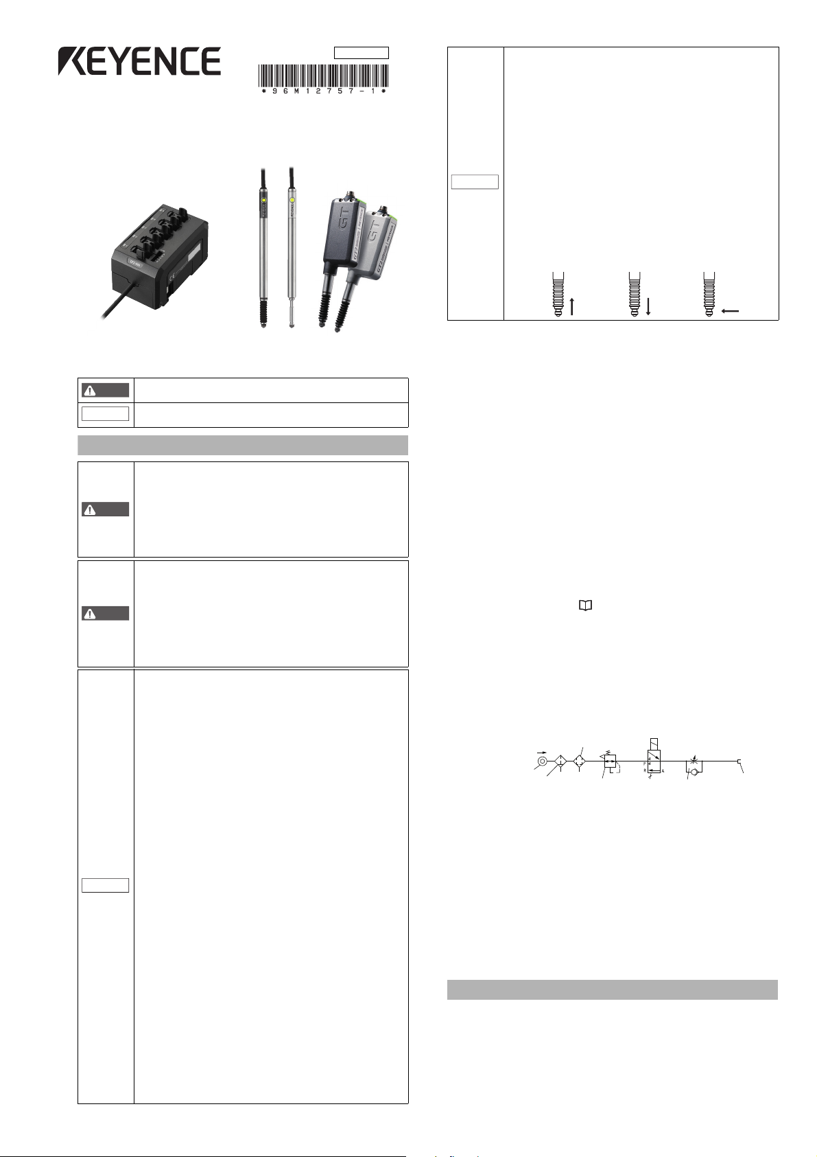
Illustration 1 - Pneuma tic circuit
High-accuracy Digital Contact Sensor
GT2-500
■
Symbols
The following symbols alert you to matters concerning the prevention of
human injury and product damage. Be sure to read these messages carefully.
Safety Information for GT2-500 Series
96M12757
Series Instruction Manual
It indicates a hazardous situation which, if not avoided,
could result in death or serious injury.
It indicates a situation which, if not avoided, could result in
product damage as well as property damage.
If the following conditions are encountered, immediately
turn OFF the power. Continuing to use the GT2-500
Series under these abnormal conditions may cause
equipment failure.
•
When water or foreign matter enters the controller
• When the GT2-500 Series is dropped or the housing is
damaged
• When the GT2-500 Series produces smoke or an
abnormal smell
• Do not use the GT2-500 Series with a voltage other
than specified voltage, as this may cause fire, electric
shock or equipment failure.
• Do not disassemble or modify the GT2-500 Series.
This may cause fire or electric shock.
• Do not use this product for the purpose to protect a
human body or a part of human body.
•
This product is not intended for use as explosion-proof
product. Do not use this product in a hazardous location
and/or potentially explosive atmosphere.
•
Be sure to turn OFF the power of the GT2-500 Series and
any connected devices before connecting or disconnecting
the cables. Otherwise, there may be a risk of damage.
•
Do not turn OFF the power while setting parameters.
Otherwise, the settings may be partially or completely lost.
•
At startup and during operation, be sure to monitor the
function performance of the GT2-500 Series.
• Do not modify the GT2-500 Series or use it in any way
other than described in the specifications.
• The function performance of products used or modified
in this way cannot be guaranteed.
•
When the GT2-500 Series is used in combination with
other instruments, function performance may be degraded,
depending on operating conditions and the surrounding
environment. Use the GT2-500 Series after fully studying
the effect of combined use with other instruments.
• Do not expose the GT2-500 Series and peripheral
devices to sudden temperature change. This may
cause condensation, damaging the equipment.
●
Environmental conditions
To use the GT2-500 Series properly and safely, do not
install the GT2-500 Series in the following locations.
Use of this equipment in an improper environment
may cause equipment failure.
•
Locations outside
•
Locations with high humidity, a large amount of dust,
or poor ventilation
•
Locations where the temperature rises excessively
due to direct sunlight, etc.
•
Locations near corrosive or flammable gas
•
Locations where the GT2-500 Series is directly
subjected to vibration or impact
•
Locations where water, oil or chemicals may come
into contact with the GT2-500 Series
•
Locations where static electricity may easily occur
●
Noise countermeasures
Installation near a source of electrical noise such as a power
source or a power cable may cause malfunction or failure of
the equipment. Adopt appropriate countermeasures against
noise by using a noise filter or wiring cables in separate ducts,
attaching insulation to the amplifier or the sensor head, etc.
●
Handling of the sensor head
•
The GT2-500 Series and peripheral devices are precision
machines. Do not drop, or cause any other impact to these
devices. Doing so may cause damage or malfunction.
•
Do not apply weight greater than what is listed below to the spindle.
Do not apply rotational torque. Otherwise the spindle may break.
•
The GT2-P12KL(F)/P12L(F)/PA12K/PA12 spindle can rotate a
maximum of about 4.5°. When using an offset contact (OP-
77683) or similar, if pressure in the rotational direction is
applied to the contact, the measurement position may change.
•
Although the GT2-PA12K/PA12/H12K/H12KF/H12/H12F/
H32/H50/A12K/A12/A32/A50 has a protection rating of
IP67, avoid using it immersed in water or in places where
liquid such as oil may come into contact with it.
•
Although the GT2-P12K(F)/P12(F) has a protection rating of
IP67G/NEMA Type 13, some types of oil may damage the device.
•
If dust, metal powder, or similar becomes attached to the
sliding part of the sensor head, mechanical responses may
become slow. If this happens, replace the dust seal with a
replacement dust seal (OP-87932). Refer to the instruction
manual included with the replacement dust seal (OP-
87932) for instructions on how to replace the dust seal
■
Other precautions
●
Effects of surrounding air temperature
To use the GT2-500 Series with high accuracy, do not use the GT2-500 Series
in an environment in which the surrounding air temperature changes sharply.
It will take about 40 minutes for the 12 mm type, and 60 minutes for the 32 mm/
50 mm type for the internal temperature to stabilize when the surrounding air
temperature has changed by 10°C.
●
Warming up
The circuit is not stable immediately after the power turns ON, which
sometimes causes the indicated value to gradually fluctuate. Wait for about
5 minutes when using the 12 mm type and about 10 minutes when using
the 32/50 mm type after the power turns on before starting operation.
●
GT2-PA12K/PA12 (See illustration 1 for the pneumatic circuit)
•
This model uses a single-acting cylinder. The internal spring will
return the sensor head to its home position.
•
The air supply hole cannot be removed.
•
Use an air filter, mist separator, etc. to provide clean dry air. Empty the
drainage from the filter regularly, before it exceeds the specified line.
•
Before connecting the air tube to the air supply hole, be sure to blow plenty of
air through the pipes (flushing) to remove any foreign matter.
•
Make sure that the air pressure of the supplied air is constant and in the range
of 0.24 to 0.26 MPa. Use a precision regulator to control the air pressure. If
the air pressure is below 0.24 MPa, the spindle may not extend fully.
•
When supplying air (with the spindle extended), up to 3L/min of air will be
emitted from the tip of the dust seal.
•
The measuring ability of the device changes according to the air pressure
of the air supply. Refer to "Specifications" (page 9) for details.
●
GT2-A12K(L)/A12(L)/A32/A50 (See illustration 1 for the pneumatic circuit)
•
This model uses a single-acting cylinder. The internal spring will
return the sensor head to its home position when air pressure is
removed. DO NOT supply air to the exhaust valve.
•
The air cylinder cannot be removed.
•
Use the regulator to supply the stable air pressure to the sensor head.
•
Use the air filter and mist separators to supply dry air. Empty the drainage
from the filter regularly, before it exceeds the specified line.
•
Make sure that the air pressure of the air supply is constant and in
the range of 0.25 MPa to 0.5 MPa.
•
The coupling socket and the exhaust valve that are supplied with the
air cylinder are dedicated for this product. They cannot be removed.
●
Power su pp ly
•
Noise superimposed on the power supply may cause malfunction. Be sure to
use the DC stabilized power supply provided with an insulation transformer.
•
In the case of a commercially available switching regulator, be
sure to ground the frame ground terminal or the ground terminal.
●
About dust boot
When the dust boot of the sensor head is damaged, use an optional dust
boot sold separately (For GT2-P12K(F)/P12(F)/H12K(F)/H12(F)/A12K/
A12: OP-84332 (Material: NBR (attached when shipped)). For GT2P12K(F)/P12(F): OP-87859 (Material: Fluororubber). For GT2-H32/A32:
OP-84459 (Material: NBR (attached when shipped)). For GT2-H50/A50
(Material: NBR (attached when shipped)).) Attach the dust boot correctly.
The dust boot may deteriorate, depending on the environment it is
used in. In this case, replace the dust boot regularly.
* Do not use the dust boot on the GT2-P12KL/P12L/PA12K/PA12/
H12KL(F)/H12L(F)/H32L.
Precautions on Regulations and Standards
■
CE Marking
●
EMC Directive (2004/108/EC)
•
Applicable standard EMI: EN61326-1, Class A
•
This product is designed for use in industrial environments.
Remarks: This specification does not give any guarantee that the end-product
with this product incorporated complies with the essential requirements of EMC
Directive. The manufacturer of the end-product is solely responsible for the
compliance on the end-product itself according to EMC Directive.
1
EMS: EN61326-1
GT2-500-M-E
.
Page 2
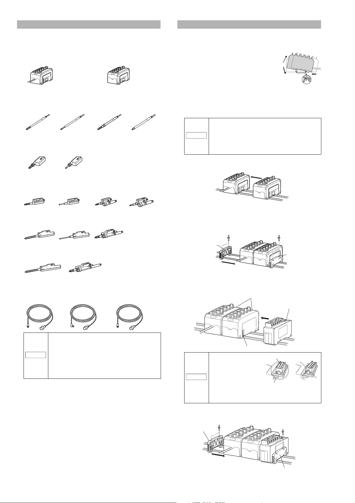
Package Contents
NOTICE
GT2-500 (Main unit) GT2-550 (Expansion unit)
Amplifier x 1 Amplifier x 1Instruction manual x 1
GT2-CH2M/5M/10M/20M
(M8 straight connector)
GT2-CHL2M/5M/10M/20M
(M8 L-shaped connector)
GT2-CHP2M/5M/10M
(M8 oil-resistant straight connector)
NOTICE
NOTICE
(1)
(2)
(3)
End unit
End unit
Amplifier
Connector
DL Series Communication Unit
Amplifier connection connector
DL Series Communication Unit
Mounting the Amplifier and Wiring
The product package of each model should include the following items.
Check that all items are included before use.
■
Amplifier parts
●
Amplifier
■
Sensor head parts
●
Sensor head
GT2-P12K/P12 GT2-P12KL/P12L GT2-PA12K/PA12
Sensor head x 1 Sensor head x 1
Precautions for handling x 1 Precautions for handling x 1
GT2-H12KF/ H12F GT2-H12KLF/H12LF
Sensor head x 1
Precautions for handling x 1
Nut x 1
Key spanner x 1
GT2-H12K/H12
Sensor head x 1 Sensor head x 1
Precautions for Handling x 1 Precautions for Handling x 1
GT2-H32 GT2-H32L
Sensor head x 1
Precautions for handling x 1
Nut x 1
Key spanner x 1
GT2-H12KL/H12L
GT2-P12KF/P12F
Sensor head x 1
Precautions for handling x 1
Nut x 1
Key spanner x 1
GT2-A12K/A12
Sensor head x 1
Precautions for handling x 1
GT2-A32
Sensor head x 1
Precautions for handling x 1
GT2-A12KL/A12L
Sensor head x 1
Precautions for handling x 1
■
Mounting the amplifier
●
GT2-500 (Main unit)
1
Fit the tab of the lower part of the main unit to
the DIN rail. While inserting the main unit in
the direction of Arrow (1), push the body down
in the direction of Arrow (2).
2
To detach the amplifier, while pushing the main unit in the direction of
Arrow (1), pull the body up in the direction of Arrow (3).
●
GT2-550 (Expansion unit)
The expansion unit can only be used in addition to the main unit.
Up to 2 expansion units can be added to one main unit.
• When adding an amplifier (expansion unit), be sure
the power of both main and expansion units is OFF
before operation. Mounting when the power is ON
may damage the equipment.
• Be sure to completely connect an expansion unit to
a main unit. Oblique or improper connections may
damage the equipment.
1
Mount the expansion unit to be added to the DIN rail.
2
Push and fix the expansion unit to the connector of the main unit until it clicks.
3
Mount the end units (OP-26751: a set of two pieces) sold separately on
both sides of the amplifiers (the main unit and the expansion unit),
then fix the end units with screws on the upper part of each end unit (2
points x 2 units).
The mounting method of the end unit is the same as that of the amplifier.
Sensor head x 1 Sensor head x 1
Precautions for Handling x 1 Precautions for Handling x 1
GT2-H50
Sensor head x 1
Precautions for Handling x 1
●
Sensor head connection cable
GT2-A50
Sensor head x 1
Precautions for Handling x 1
Sensor head x 1
Precautions for Handling x 1
• The M8 L-shaped connector type cable cannot be
used with the GT2-H32(L)/H50/A32/A50.
• When a protection rating of IP67G and NEMA Type
13 enclosure is required for GT2-P12K(F)/P12(F),
or a protection rating of IP67G is required for GT2PA12K/GT2-PA12 use an M8 oil-resistant straight
connector type cable. Other cables do not meet the
IP67G protection rating or NEMA Type 13
enclosure rating.
We have taken all possible precautions in packaging; however, if
any parts are found to be defective or broken, please contact your
nearest KEYENCE sales office.
■
Connecting to DL Series Communication Units
For details on communication methods, see the DL Series manuals.
1
Attach the DL Series to the DIN rail and connect it to the amplifier.
Refer to the illustration on
the right to check that the
sensor amplifier
connection connector (for
attaching to DIN rails) on
the side of the DL Series
Communication Unit is
not bent. Connecting to
the sensor amplifier with a bent connector can lead to
equipment damage.
2
Attach 1 end unit (OP-26751: 2 units) to the side of the amplifier, and 1
to the side of the DL Series Communication Unit. Attach using the
screws on top of the end units (2 screws on each unit).
End unit
GT2-500-M-E
End unit
2
Page 3
●
20 - 30 V DC
Brown
Blue
Operation indicator
Relay connector
Cable
connector
Dust boot
Mounting fixture
Dust boot
※
Spindle
Contact
Dust boot
●
GT2-P12K(L)/P12(L)
●
GT2-P12KF/P12F
Cable between
the sensor
head and relay
connector
●
GT2-PA12K/PA12
Relay connector
Cable
connector
Cable
connector
Cable
between the
sensor head
and relay
connector
Operation indicator
Cable between
the sensor
head and relay
connector
Mounting fixt ure
Operation indicato r
Contact
Spindle
Air supply hole
Dust seal
*1 A mounting bracket is attached to
GT2-H12KF/H12F/H12KLF/H12LF.
*2 Not included in the GT2-H12KL/H12L/H12KLF/H12LF.
Contact
Head indicator
Cable connector
Mounting fixture*
1
Dust boot*
2
*3 Not included in the GT2-H32L.
Contact
Head indicator
Cable connector
Mounting fixture
Dust boot*
3
Contact
Dust boot
Spindle
Dust boot
Dust boot*
Dust boot
Coupling socket
Coupling socket
Air cylinder
Air cylinder
Head indicator
Head indicator
Cable connector
Cable connector
Exhaust valve
Exhaust valve
Spindle
Contact
Mounting fixture
Mounting fixture
Contact
Contact
* Not included in the GT2-A12KL/A12L.
Arrow
Unlocked
Click
Lock cover
Lock lever
Locked
Lock cover
Power cable
The power cable is as follows:
GT2-500 (Main unit)
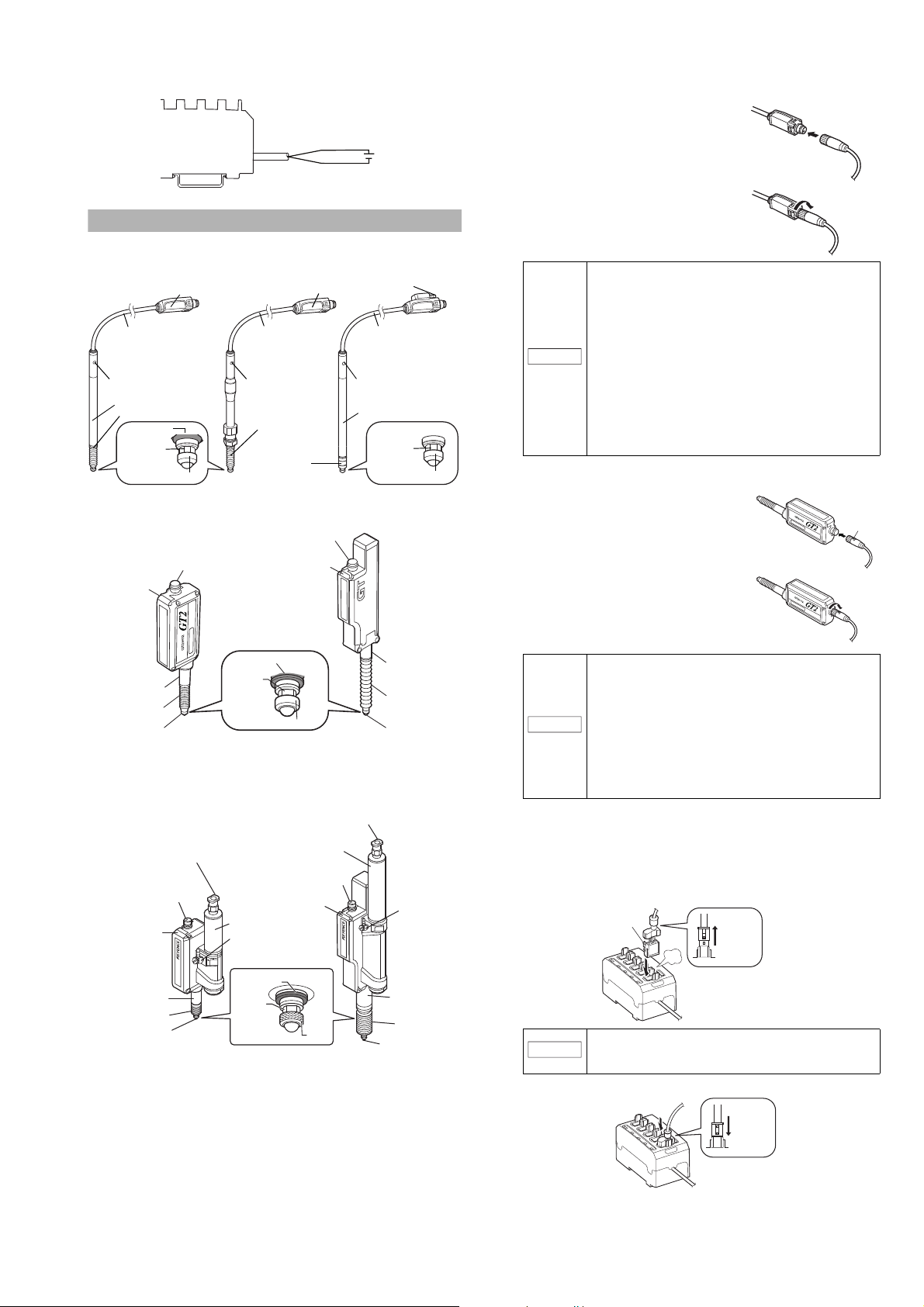
Connecting and Mounting the Sensor Head
■
Names of parts of the sensor head
* Not included in the GT2-P12KL/P12L.
●
GT2-H12K(L)(F)(LF)/H12(L)(F)(LF)/H32(L)/H50
■
Connecting the sensor head connection cable
●
For GT2-P***/PA***
1
Insert the sensor head connection
cable into the cable connector on the
relay connector cable.
2
Secure the connector with the sensor
head connection cable screw.
• When connecting the connector, be sure to insert it
straight, and tighten it securely. (Recommended
tightening torque: 0.4 to 0.5 N
If the connection is not tight enough, the connector
may be loosened by vibration or other causes,
・
m*)
leading to a connection failure.
(* After tightening it firmly by hand, use pliers or
NOTICE
other tools to rotate it about 30° for further
tightening.)
• When the head is attached to a moving part, and
the cable will be repeatedly bent, ensure that the
cable between the sensor head and relay
connector does not bend. Instead, bend the sensor
head cable connecting the relay connector and the
amplifier.
●
For units other than GT2-P***/PA***
1
Insert the sensor head connection cable
into the cable connector of the sensor
head.
●
GT2-A12K(L)/A12(L)/A32/A50
2
Secure the connector by rotating the
grooved portion.
• When connecting the connector, be sure to insert it
straight, and tighten it securely. (Recommended
・
m*)
NOTICE
tightening torque: 0.4 to 0.5 N
If the connection is not tight enough, the connector
may be loosened by vibration or other causes,
leading to a connection failure.
(* After tightening it firmly by hand, use pliers or
other tools to rotate it about 30° for further
tightening.)
• The M8 L-shaped connector (GT2-CHL*M) cannot
be used with the GT2-H32(L)/H50/A32/A50.
To disconnect the sensor head connection cable, reverse the steps
above.
■
Connecting the amplifier
1
Remove the lock cover of the connector of the sensor head
connection cable, and insert the sensor head connection cable into
the connector on the side of the amplifier until it clicks.
To disconnect the sensor head connection cable,
NOTICE
2
Put the lock cover on the connector, and lock the lock cover.
press and hold the lock lever on the side of the
connecter and disconnect the cable.
3
GT2-500-M-E
Page 4

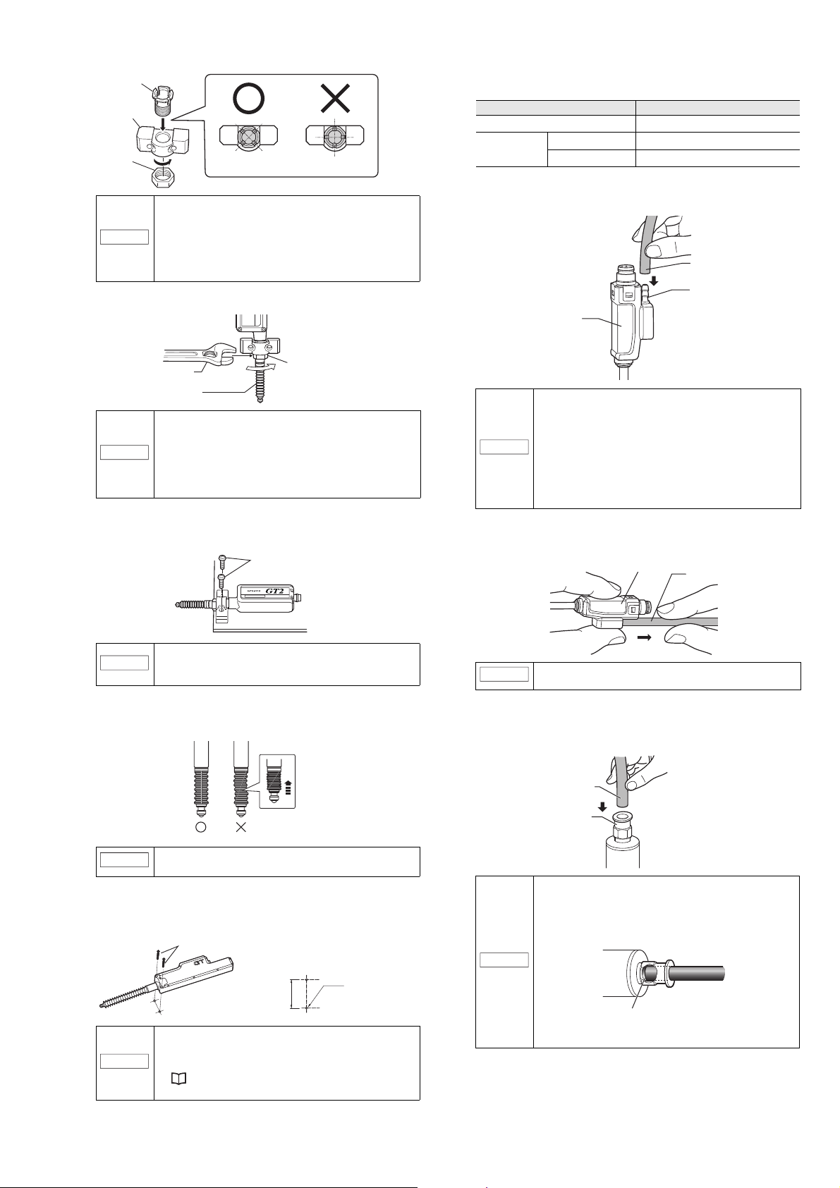
■
NOTICE
NOTICE
Tightening sleeve
Key wrench
Nut
Optional head mounting
bracket A (OP-76874)
Tightening sleeve
Key wrench
Nut
Optional head mounting
bracket C (OP-84396)
●
GT2-P12K(L)/P12(L)/PA12K/PA12/
H12K(L)/H12(L)/A12K(L)/A12(L)
●
GT2-H32(L)/H50/A32/A50
NOTICE
When mounting the
GT2-H32L facing
upward, be sure to
use the mounting
holes on the side of
the sensor head. If
the sensor head is
mounted using head
mounting bracket D,
the spindle may not
fully extend.
Mounting
illustration
φ10
+0.005
+0.1
Nut
mounting
side
*1.
For head mounting bracket C or
flange types (model names that end in F)
*2. Processing accuracy : ±0.05
φ10 G8
( )
*1
+0.005
+0.027
0.5 to 1.0
*2
5.5 to 11.3
*2
A
45°
±1°
φ0.025
A
(Unit: mm)
Tightening
sleeve
insertion
side
●
GT2-P12K(L)/P12(L)/PA12K/PA12/
H12K(L)/H12(L)/A12K(L)/A12(L)
●
GT2-H32(L)/H50/A32/A50
Tightening
sleeve
Nut
Chamfered side
Sensor head
Chamfered side
Nut
Key wrench
Dust boot
Wrench
NOTICE
8.5
8
+
0
.
2
0
0
+
0
.
0
0
5
M
4
x
0
.
7
Make sure that the metal plating
mounting bracket F attaches to is made
of SUS (SUS303 reco mmended) and is
at least 5 mm thick.
•
GT2-P12K(L)/P12(L)/PA12K/PA12
Mounting the sensor head
●
Mounting directly to the jig
Before mounting the sensor head directory to the jig, create a hole
in the jig. Attach the sensor head using the optional head mounting
bracket sold separately. A mounting bracket is provided with the
GT2-P12KF/P12F/H12K(L)F/H12(L)F as standard. Attach it with the
supplied nut.
Optional head mounting
bracket D (OP-84327)
Tightening sleeve
Key wrench
1
Cut the jig to create a sensor head mounting hole referring to the
illustration below.
Nut
4
Rotate the dust boot so that the side line is straight. (Models other
than GT2-PA12K/PA12)
Check with the spindle pushed in.
NOTICE
●
Using mounting bracket F
1
Refer to the illustration below and cut the jig to create a sensor
If the dust boot is not straight, it becomes easier to
damage when the spindle is moved.
head mounting hole.
2
Loosen the screw on the side of mounting bracket F using the
supplied hexagonal wrench.
0.5 to 1.0
±1°
45°
Tightening
sleeve
insertion
+0.1
+0.006
φ14
2
Insert the tightening sleeve into the hole (from the Chamfered side),
side
φ0.025
A
and loosely tighten with the nut.
In the illustration on the left, if the nut is fully tightened
when the sensor head is not yet inserted, the fixture
will become deformed.
3
Insert the sensor head in the tightening sleeve. While securing the tightening
sleeve with the included key wrench, tighten the nut with a separate wrench.
A
Nut
mounting
side
5.5 to 11.3
(Unit: mm)
*2
*2
3
Align mounting bracket F with the hole made in step 1 and
secure it using the supplied hexagonal wrench.
4
Insert the sensor head, and tighten the screw loosened in step
2 using the supplied hexagonal wrench to secure. The
recommended tightening torque is 0.6 to 0.8 N•m. Make sure
that the dust boot does not obstruct the metal plating that
mounting bracket F is attached to.
• Make sure that the dust boot does not become
damaged during the procedure.
• When loosening the screw with the hexagonal
wrench, insert the long end of the hexagonal
wrench into the hex screw and rotate the small end
with your hand.
• Do not forcibly tighten the hex screw.
• Cannot be used with GT2-P12KF/P12F/H***/A***.
●
Mounting on the side of a surface
When mounting to the side of a GT2-P12K(L)/P12(L)/PA12K/PA12/
H12K(L)/H12(L)/A12K(L)/A12(L) unit, use the optional head
mounting bracket B (OP-76875).
Mounting illustration
Optional head mounting bracket B
(OP-76875)
Tightening sleeve Nut Mounting bracket
Tightening the nut while fixing the sensor head may
lead to damage.
• The tightening torque for mounting bracket A (OP-
GT2-500-M-E
•
76874), mounting bracket C (OP-84396), and the
nuts supplied with GT2-H12K(L)F/H12(L)F/P12KF/
P12F is between 5 and 7 N
tightening torque is 5 N
between 15 and 18 N
the GT2-A32/A50) to head mounting bracket D (OP-
84327). Use the wrench that matches the nut width.
Care must be taken not to damage the dust boot
when tightening.
・
m (the recommended
・
m). Apply tightening torque
・
m (20 to 23 N・m when using
4
Page 5
1
NOTICE
NOTICE
NOTICE
NOTICE
NOTICE
Tightening sleeve
Mounting bracket
Nut
Notice the correct angle of the tightening sleeve.
Nut
Wrench
Dust boot
M4 screws
Mounting illustration
M4 tap
23 ± 0.15 mm
M4 screws (Mounting hole dimensions)
Air tube
Air supply hole
Relay connector
Relay connector
Air tube
Air tube
Coupling socket
Insert the tightening sleeve into the mounting bracket from the side
with a depression, and loosely tighten with the nut.
• If the sleeve is inserted from the wrong side, the
sensor head cannot be secured.
• Strongly tightening the nut without the sensor head
inserted may deform the tightening nut.
• Head mounting bracket B cannot be used in
combination with head mounting bracket C (OP-
84396) or head mounting bracket D (OP-84327).
2
Insert the sensor head into the tightening sleeve, and tighten the nut
with a wrench.
Tightening the nut while fixing the sensor head may
lead to damage.
• Apply a tightening torque of 5 to 7 N
recommended tightening torque is 5 N
wrench that fits the width of the nut.
・
m (the
・
m). Use the
• Care must be taken not to damage the dust boot
when tightening.
3
Secure the sensor head with M4 screws.
Mount the sensor head with the model label on top. For GT2-P12K(L)/
P12(L)/PA12K/PA12, mount so that the head indicator is on top.
■
Installing the Air Tube
●
Compatible air tube
Use a tube with the following specifications.
Item Description
Recommended tubing material Urethane
Tubing size
●
How to Attach/Detach the Air Tube (GT2-PA12K/PA12)
Attaching the air tube
•
Insert the air tube into the air supply hole on the relay connector.
Outer diameter
Inner diameter
4 mm
2.5 mm
• For best results, cut the end of the tube at a right
angle, and ensure that the outer perimeter is not
damaged, and that it still maintains a circular cross
section.
NOTICE
• If the tube is not properly inserted, air leakage may
result.
• After attaching, pull on the tube to make sure it is
secure.
• Use a urethane tube. Make sure it also has a
bending radius of at least 50 mm.
Detaching the air tube
•
To detach the air tube, pull the air tube in the direction of the arrow,
as indicated in the figure below.
• Never apply tightening torque over 1.4 N・m.
• Care must be taken not to damage the dust boot
when tightening.
4
Rotate the dust boot so that the side line is straight. (Models other
than GT2-PA12K/PA12)
Check with the spindle pushed in.
If the dust boot is not straight, it becomes easier to
damage when the spindle is moved.
●
Mounting to the mounting holes
The mounting holes on the side of the GT2-H32(L)/H50/A32/A50
unit can be used to install to the side of a table or other surface.
• Roughness of the mounting surface may cause the
sensor to tilt, and sufficient accuracy may not be
obtained. When performing a high-accuracy
measurement, use a jig to mount the sensor head.
"Mounting directly to the jig" (page 4)
• Apply tightening torque between 1.2 and 1.5 N
NOTICE
●
How to Attach/Detach the Air Tube (GT2-A12K(L)/A12(L)/A32/A50)
Attaching the air tube
•
Feed the tubing into the socket until it bottoms out (about 1/2").
Before detaching the tube, be sure to stop any air flow.
The socket will ensure a tight seal around the tubing.
• For best results, cut the end of the tube at a right
angle, ensure that the outer perimeter is not
damaged, and that it still maintains a circular cross
section.
• If the tube is not properly inserted, air leakage may
result (see figure below).
NOTICE
• After attachment, pull on the tube to make sure it is
secure.
・
m.
5
Tube end
GT2-500-M-E
Page 6

Detaching the air tube
NOTICE
NOTICE
Release ring
(2)
(1)
Screw
Air tube
Air tube
Exhaust valve
Speed controller
Air supply
Indication symbol
Adjusting the speed.
NOTICE
Spindle
Contact
Key wrench
Pliers
Cover the contact
with a cloth
GT2-500 (Main unit) GT2-550 (Expansion unit)
A
B
C
D
E
ON
•
To detach the air tube, (1) press down on the release ring, (2) pull
out the tube.
• Before detaching the tube, be sure to stop any air
flow.
• Press down on the release ring evenly from both
sides, and pull the tube out. Uneven pressure may
result in damage to the tube or damage to the
operation of the air cylinder.
●
For GT2-A12K/A12/A32/A50 when an IP67 enclosure
rating is required
To maintain an IP67 enclosure rating for GT2-A12K/A12/A32/A50,
the following must be satisfied:
•
Firmly connect tubing with 2.5 mm inner diameter to the exhaust
port until it bottoms out.
Ensure that the tube end is free of dirt or water.
•
Tighten the screw of the exhaust valve with a torque of 0.5 to 0.6 N・m.
If the screw is loose, the IP67 rating cannot be guaranteed.
Reference
By loosening the screw of the exhaust valve, you can
change the exhaust port angle.
Contact
This section describes how to replace the contact, and how to mount
the lift lever.
• Detach the sensor head from the device or fixture
(metal plating, etc.) before replacing the contact.
• When applying pliers to the contact, be sure not to
rotate the main part and cover the contact with a cloth.
• Never apply tightening torque over 0.2 N
attaching a contact.
• Fix the roller contact (OP-77680) or the offset contact
(OP-77683) with the fixing nut in the same direction as in
actual use.
• Applying an adhesive, a thread locking agent, is
recommended to prevent the nut from getting loose.
• Position the roller contact carefully in the proper
direction. Care must be taken not to apply misdirected
force to the shaft.
■
How to replace the contact
・
m when
While securing the spindle with the accessory key wrench, detach
the contact with pliers. Then attach a new contact.
How to replace the dust seal
Refer to the instruction manual included with the replacement dust seal
(OP-87932).
■
How to mount the lift lever
Mount the lift lever (OP-84397) between the spindle and the contact.
Secure the spindle with the lift lever and attach/detach the contact.
●
Adjustment of Spindle Movement Speed
To adjust the spindle movement speed, install a speed controller
between the cylinder and the air supply. Using OP-87970 is
recommended.
• To further decrease spindle movement speed, use
a coil-shaped tube (OP-87986) or similar to
increase the distance between the air supply hole
and the speed controller.
• The speed controller will not operate if installed in
the reverse direction.
GT2-500-M-E
Amplifier part names and descriptions
Up to 5 sensor heads can be connected to 1 main unit/expansion
unit amplifier. Up to 2 expansion units can be added to 1 main unit.
Therefore, up to 15 sensor heads can be connected in total.
Item Explanation
①
Sensor head
connector
②
DIP switch
③
Status light
④
Powe r cable
Connect to a sensor head cable with a sensor head attached.
Refer to "Connecting the amplifier" (page 3) for details.
Channels set to ON (enable) can recognize sensor hea ds.
The factory default setting for all switches is ON.
Switch channels that will not be used to OFF (disable).
*
Be sure to change DIP switch settings with the power off.
If the equipment is turned on while the DIP switch settings are
changed, setting changes will not be effective.
Changes are applied when the power is turned on.
Lit in green:Normal. Lights when the DIP switch is set to ON
Lit in red: Error. Lights when the DIP switch is set to ON (enabled),
Not lit: Disabled Stays unlit when the DIP switch is set to OFF
Supplies power. The cable is 2 m long.
Expansion units do not have power cables. Power is supplied to
expansion units through the main unit.
(enabled), and the sensor heads are corrected properly.
and there is an error.
See page 8 for information on checking errors and taking
corrective action.
(disabled).
If a sensor head is connected, it will not be automatically
recognised (the sensor head indicator will not light up).
6
Page 7

●
Reference
Enabling/disabling the DIP switches and sensor heads
Each channel can be enabled or disabled by switching the DIP switch
ON/OFF.
Channel A on the main unit is always enabled,
regardless of the DIP switch setting.
Channel B/C/D/E on the main unit can be enabled or
disabled using the DIP switches.
Channel A/B/C/D/E on the expansion unit can be
enabled or disabled using the DIP switches.
Example of recommended DIP switch settings (when using 7 sensor
heads)
Main
DIP switch
unit
ON/OFF
A ON Enabled A ON Enabled
B ON Enabled B ON Enabled
C ON Enabled C OFF Disabled
D ON Enabled D OFF Disabled
E ON Enabled E OFF Disabled
●
ID assignment when connected to a DL Series Communication Unit
Criterion values (measurement values) cannot be output to external
equipment and settings cannot be changed using only this equipment.
Enable/
Disable
Expansion
unit
DIP switch
ON/OFF
Enable/
Disable
Use a DL Series Communication Unit to perform these procedures.
Connect this equipment to the DL Series Communication Unit.
"Connecting to DL Series Communication Units" (page 2)
For details on communication between this equipment and the DL
Series, see the DL Series Communication Unit manuals.
An ID number is automatically assigned to each channel when using a
DL Series Communication Unit.
ID numbers are assigned to enabled channels in order, from channel A
on the main unit.
When not using DL-RS1A/DL-RB1A
Main
DIP switch
unit
A OFF Enabled 01 A OFF Disabled - A ON Enabled 08
B ON Enabled 02 B ON Enabled 05 B OFF Disabled -C OFF Disabled - C OFF Disabled - C ON Enabled 09
D ON Enabled 03 D ON Enabled 06 D ON Enabled 10
E ON Enabled 04 E ON Enabled 07 E OFF Enabled 11
ON/OFF
Enable/
Disable
Expansi
DIP switch
ID
on unit 1
ON/OFF
Enable/
Disable
Expansi
DIP switch
ID
on unit 2
ON/OFF
Enable/
Disable
Cautions
• If, for example, channel C on the main unit is enabled during use, the
ID for channel C becomes 03, and each subsequent ID has 1 added
to it.
Therefore it may be necessary to change the PLC program.
• When a channel is enabled but no sensor head is connected, it is
recognized as a head error.
ID
The example below shows 1 main unit (GT2-500) connected to 2
expansion units (GT2-550) (the expansion unit connected to the main
unit is expansion unit 1, and the expansion unit connected to expansion
unit 1 is expansion unit 2), with 11 sensor heads being used in total.
Example 1: When connected in order from channel A on the main unit
When using DL-RS1A/DL-RB1A
Main
DIP switch
unit
A ON Enabled 00 A ON Enabled 05 A ON Enabled 10
B ON Enabled 01 B ON Enabled 06 B OFF Disabled C ON Enabled 02 C ON Enabled 07 C OFF Disabled D ON Enabled 03 D ON Enabled 08 D OFF Disabled E ON Enabled 04 E ON Enabled 09 E OFF Disabled -
ON/OFF
Enable/
Disable
Expansion
DIP switch
ID
unit 1
ON/OFF
Enable/
Disable
ID
Expansion
unit 2
DIP switch
ON/OFF
Enable/
Disable
When not using DL-RS1A/DL-RB1A
Main
DIP switch
unit
A ON Enabled 01 A ON Enabled 06 A ON Enabled 11
B ON Enabled 02 B ON Enabled 07 B OFF Disabled C ON Enabled 03 C ON Enabled 08 C OFF Disabled D ON Enabled 04 D ON Enabled 09 D OFF Disabled -
E ON Enabled 05 E ON Enabled 10 E OFF Disabled
ON/OFF
Enable/
Disable
Expansion
DIP switch
ID
unit 1
ON/OFF
Enable/
Disable
ID
Expansion
unit 2
DIP switch
ON/OFF
Enable/
Disable
Example 2: When connected in a random order
When using DL-RS1A/DL-RB1A
Main
DIP switch
unit
A OFF Enabled 00 A OFF Disabled - A ON Enabled 08
B ON Enabled 01 B ON Enabled 05 B OFF Disabled --
C OFF Disabled - C OFF Disabled - C ON Enabled
D ON Enabled 02 D ON Enabled 06 D OFF Disabled -E ON Enabled 03 E ON Enabled 07 E ON Enabled 10
ON/OFF
Enable/
Disable
Expansion
DIP switch
ID
unit 1
ON/OFF
Enable/
Disable
ID
Expansion
unit 2
DIP switch
ON/OFF
Enable/
Disable
Cautions
• If, for example, channel C on the main unit is enabled during use, the
ID for channel C becomes 02, and each subsequent ID has 1 added
to it.
Therefore it may be necessary to change the PLC program.
• When a channel is enabled but no sensor head is connected, it is
recognized as a head error.
ID
ID
-
ID
09
7
GT2-500-M-E
Page 8

Functions that can be set using DL Series Communication Units
Troubleshooting
See the GT2-70 Series user manual for information about each
function.
See the DL Series manuals for information on using the
Communication Units.
The user manuals for DL Series Communication Units and the GT2-70
Series can be downloaded from the KEYENCE website.
http://www.keyence.com/
Listed below are the main functions of the GT2 Series and where to
find information about them in the GT2-70 Users Manual.
Item
Origin Alignment Chapter 3
Setting the Tolerances Chapter 3
HH/Setting the HH/LL Criterion Value Chapter 3
Preset Function (Adding or Subtracting a Desired Value) Chapter 3
Bank Function (Registering Multiple Criterion Values and
Preset Values)
Reset Input (Resetting Internal Values) Chapter 3
Hysteresis Chapter 3
Initialization (Initial Reset) Chapter 3
Judging with the Current Value Chapter 4
Judging after the Detection Value is Stabilized Chapter 4
Judging by the Maximum Value (Peak Hold) Chapter 4
Judging by the Minimum Value (Bottom Hold) Chapter 4
Judging with the Difference between Maximum and
Minimum Values (Peak to Peak Hold Detection Mode)
Holding HIGH/LOW Output (NG Hold) Chapter 4
Detection Mode Chapter 5
Hold Update Method Chapter 5
Response time Chapter 5
Timing Type Chapter 5
Self-timing Level Chapter 5
Self Timing Delay Types Chapter 5
User-specified Delay Time Chapter 5
Static Hold Delay Stability Chapter 5
Static Hold Delay Stability Width Chapter 5
Measurement Direction Chapter 5
Multiplier Chapter 5
Batch Input Settings Chapter 5
Special Output Setting Chapter 5
Limit Output HH Side Teaching Chapter 5
Limit Output HH Side Criterion Position Setting Chapter 5
Limit Output LL Side Teaching Chapter 5
Limit Output LL Side Teaching Criterion Position Setting Chapter 5
Select Preset Data Chapter 5
Store Preset Value Chapter 5
Preset Point Chapter 5
Power Save Function Chapter 5
Jam Detection Function Chapter 5
Jam Detection Teaching Chapter 5
Jam Detection Checkpoint Setting Chapter 5
Calculation Setting Mode Chapter 5
Timing Chart Chapter 5
See the GT2-70 Series user manual for information about the items
listed below.
Item
List of Optional Parts Chapter 1
Replacing the Contact Appendix
Replacing the Dust Boot Appendix
How to Mount the Lift Lever Appendix
Reference
chapter
Chapter 3
Chapter 4
Reference
chapter
When there is a malfunction, the status light on the sensor amplifier
lights in red.
If you are using a DL Series Communication Unit (excluding DL-RB1A),
details of the error can be checked via the Communication Unit. See
the DL Series manuals for information on using the Communication
Units.
Problem Cause Corrective action
Sensor head
error
EEPROM
error
Jam
detection
error
Self timing
delay error
Unit number
error
Calculation
error
Calculation
only mode
error
• The sensor head is
disconnected.
• The sensor head cable is
broken.
• The sensor head is
damaged.
• Failed to write data.
• The spindle is jammed.
(When using the jam
detection function)
• The value fell below (rose
above) the timing level
during the set delay time.
• The value fell below (rose
above) the timing level
before the detection status
was stable and the
criterion level (P.V. value)
was fixed when using
static hold internal timing.
• The value rose above (fell
below) the timing level,
then fell below (rose
above) the timing level
before the criterion level
(P.V. value) was fixed when
using delay timer internal
timing.
• When using the calculation
function, the number of the
expansion unit when the
power is turned ON differs
from the number of the
expansion unit in the
memory of the main unit
when the calculation is set.
• When using the calculation
function, a model other
than the GT2-500/70
Series is added.
• When using the reference
difference calculation
function, an error occurred
in the main unit.
When using other than the
reference difference
alculation function, an
c
error occurred in an
expansion unit.
• The sensor head is
connected to the main unit
in which the calculation
only mode is set.
• Connect the sensor
head.
• Replace the sensor
head cable.
• Replace the sensor
head.
• Turn the equipment off
and on, and perform
initial reset. (If this
does not solve the
problem, the
equipment may be
damaged, or may have
reached the end of its
service life. Replace
the amplifier unit.)
• If the spindle is
jammed and does not
move, replace the
sensor head.
Use a Communication
Unit to check that the
timing input is
appropriate.
• Make sure that the
value does not fall
below (rise above) the
timing level before the
criterion value is fixed.
Alternatively, lengthen
the static hold delay
stabilizing amplitude
so that the criterion
value can be easily
fixed.
• Reset the calculation
mode or perform initial
reset of the main unit.
Perform initial reset via
the Communication
Unit. See the DL
Series manuals for the
method.
• Check each main/
expansion unit for the
cause of the error.
• Remove the sensor
head from the main
unit or set a mode
other than the
calculation only mode.
GT2-500-M-E
8
Page 9

Specifications
■
Sensor head
GT2-P***/PA*** cannot be connected to amplifier units purchased before April 15th 2014.
●
Pencil type (GT2-PA12K/PA12 are air cylinder types)
Model
Detection system Scale shot system II Absolute type (without tracking error)
Measuring range
Resolution
Indication accuracy
Measuring force
Sampling interval
Mechanical response
*1
When installed facing down 1.0 N 0.2 N 1.0 N 0.2 N 1.2 N
*2
When installed sideways
When installed facing up
*1
Pressure range - 0.24 to 0.26 MPa
Max. pressure - 0.5 MPa
Fluid to use -Clean dry air
Operation indicator 2-color LED (red, green)
Enclosure rating
Environmental
resistance
Surrounding air
temperature
Relative humidity 35 to 85% RH (No condensation)
Vibration resistance 10 to 55 Hz, Compound amplitude 1.5 mm, 2 hours each in X, Y, and Z axis
Shock resistance
Main unit
Material
Head cable Sold separately (connected to relay connector)
Weight (excluding c able)
*1 When the surrounding temperature is
*2 This is a typical value at the center of the measuring range. The measuring force varies depending on the mounted condition of the dust boot.
For GT2-PA12K/PA12, this is a representative value when using 0.25 MPa. The measuring force varies depending on the air pressure used. See table 1 for more det ails.
There is no dust boot for GT2-PA12K/PA12.
*3 When using an M8 oil resistant cable (GT2-CHP2M/5M/10M) as the sensor head cable.
*4 The contact is a separately sold option.
*5 Including the relay connector.
Note: Cannot be used with amplifier units purchased before April 15th, 2014.
●
Box type
Dust boot
Contact point
*5
*4
20°C.
Modeml
Detection system Scale shot system II Absolute type (without tracking error)
Measuring range 12 mm 32 mm
Resolution 0.1 µm 0.5 µm
Indication accuracy
Measuring force
Sampling interval 1 ms
Mechanical response
*1
When installed facing down 1.0 N 0.4 N 1.0 N 0.4 N 1.0 N 0.4 N 1.0 N 0.4 N 2.1 N 1.2 N 3.2 N
*2
When installed sideways 0.9 N 0.3 N 0.9 N 0.3 N 0.9 N 0.3 N 0.9 N 0.3 N 1.8 N 0.9 N 2.8 N
When installed facing up 0.8 N 0.2 N 0.8 N 0.2 N 0.8 N 0.2 N 0.8 N 0.2 N 1.5 N 0.6 N 2.4 N
*1
Operation indicator 2-color LED (red, green)
Enclosure rating IP67 - IP67 - IP67 - IP67 - IP67 - IP67
Environmental
resistance
Surrounding air temperature
Relative humidity 35 to 85% RH (No condensation)
Vibration resistance 10 to 55 Hz, Compound amplitude 1.5 mm, 2 hours each in X, Y, and Z axis
Shock resistance
Main unit Main unit cover: zinc die-cast, Indicator: polyarylate (PAR)
Material
Dust boot NBR - NBR - NBR - NBR - NBR - NBR
Contact point
*3
Cable Sold separately (connected to M8 connector)
Weight (excluding cable)
*1 When the surrounding temperature is
*2 This is a typical value at the center of the measuring range. The measuring force varies depending on the mounted condition of the dust boot.
*3 The contact is a separately sold option.
20°C.
GT2-P12K GT2-P12KF GT2-P12KL GT2-P12 GT2-P12F GT2-P12L GT2-PA12K GT2-PA12
12 mm
0.1 µm 0.5 µm 0.1 µm
1 µm (P-P) 2 µm (P-P) 1 µm (P-P)
0.5 µm
2 µm (P-P)
0.95 N 0.15 N 0.95 N 0.15 N 1.15 N
0.9 N 0.1 N 0.9 N 0.1 N 1.1 N
4 ms
10 Hz 4 Hz 10 Hz 4 Hz -
IP67G (JIS)
IP67 (IEC)
NEMA Type 13
*
3
*
3
-
IP67G (JIS)
NEMA Type 13
IP67 (IEC)
*
3
*
3
-
IP67 (IEC)
-10 to +55°C (No freezing) 0 to +55°C (No freezing)
2
Main unit cover: SUS303, Spindle for GT2-PA12K/PA12: SUS430 (Fluorine-based coating),
1000 m/s
Dust seal (GT2-PA12K/PA12 only): SUS303/SU304/aluminium (alumite treated)/special polyester fiber
Indicator: PET, Sensor head - Connection cable: PUR, Connector: PBT,
(IEC60068-2-27)
NBR - NBR -
SUS304, tungsten carbide SUS304, SUS440C
SUS304,
tungsten
carbide
SUS304,
SUS440C
Approx. 35 g Approx. 45 g Approx. 35 g Approx. 45 g Approx. 35 g
GT2-H12K GT2-H12KL GT2-H12KF GT2-H12KLF GT2-H12 GT2-H12L GT2-H12F GT2-H12LF GT2-H32 GT2-H32L GT2-H50
1 µm (P-P) 2 µm (P-P) 3 µm (P-P)
10 Hz 4 Hz 10 Hz 4 Hz 10 Hz 4 Hz 10 Hz 4 Hz 6 Hz 5 Hz 7 Hz
-10 to +55°C (No freezing)
2
1000 m/s
(IEC60068-2-27)
SUS304, tungsten carbide SUS304, SUS440C
Approx.
95 g
Approx.
95 g
Approx.
100 g
Approx.
100 g
Approx.
95 g
Approx.
95 g
Approx.
100 g
Approx.
100 g
Approx. 270 g
Approx.
50 mm
3.5 µm
(P-P)
320 g
9
GT2-500-M-E
Page 10

●
0123456789101112
Measuring force (N)
Spindle retractedSpindle extended
Table 1. Relationship between spindle position and measuring force grouped according to used air pressure.
(When installing side mounting, the measuring force is -0.05 N. When installing upward mounting, the measuring force is -0.1 N.)
Spindle position (mm)
Applied pressure (MPa)
1.7
1.2
0.26 MPa
0.25 MPa
0.24 MPa
0.7
Air cylinder type
Model GT2-A12K GT2-A12KL GT2-A12 GT2-A12L GT2-A32 GT2-A50
Detection system Scale shot system II Absolute type (without tracking error)
Measuring range 12 mm 32 mm 50 mm
Resolution 0.1 µm 0.5 µm
Indication accuracy
Measuring
*2
force
*1
When installed
facing down
When installed
sideways
When installed
facing up
1 µm (P-P) 2 µm (P-P) 3 µm (P-P) 3.5 µm (P-P)
1.2 N 0.4 N 1.2 N 0.4 N 2.1 N 3.2 N
1.1 N 0.3 N 1.1 N 0.3 N 1.8 N 2.8 N
1.0 N 0.2 N 1.0 N 0.2 N 1.5 N 2.4 N
Sampling interval 1 ms
Operation indicator 2-color LED (red, green)
Pressure range 0.25 to 0.5 MPa
Max. pressure 1.0 MPa
Fluid to use Dry air
Enclosure rating
Surrounding
Environmental
resistance
air temperature
Relative humidity
*4
Vibration
Shock resistance
Main unit cover: zinc die-cast, Cylinder: aluminum alloy, Air coupling socket (resin part): polyacetal, Air coupling socket (metal part): nickel plated brass, Indicator: polyarylate (PAR)
*5
Material
Main unit
Dust boot FKM - NBR - NBR
Contact point
*3
IP67
SUS304, tungsten
carbide
-
IP67
*3
-
0 to +55°C (No freezing)
35 to 85% RH (No condensation)
10 to 55 Hz, Compound amplitude 1.5 mm, 2 hours each in X, Y, and Z axis
1000 m/s2 (IEC60068-2-27) -
SUS304, SUS440C SUS304, SUS440C
IP67
*3
Sensor head cable Sold separately (connected to M8 connector)
Weight (excluding sensor
head cable)
*1 When the surrounding temperature is
*2 This is a typical value at the center of the measuring range. The measuring force varies depending on the mounted condition of the dust boot.
*3 Connect an air tube to the exhaust valve so that no foreign materials enter from the valve.
*4 When using mounting bracket D (OP-84327) with GT2-A32/A50, vibration is 0.75 mm.
*5 The contact is a separately sold option.
20°C.
Approx. 145 g Approx. 340 g Approx. 405 g
■
Amplifier
Model
Main unit/Expansion unit
GT2-500 GT2-550
Main unit Expansion unit
Ty pe Mount type
Number of units that can be added
Supply voltage
*
20 to 30 V DC, including 10% ripple (P-P) (power is supplied to GT2-550 from the main unit)
Current consumption
Response time
Environmental
resistance
Surrounding air
temperature
Relative humidity
Vibration resistance
(hsp (12 ms), 20 ms, 40 ms, 400 ms, 2000 ms, 4000 ms when using GT2-P***/PA*** with a sensor head)
10 to 55 Hz, Compound amplitude 1.5 mm, 2 hours each in X, Y, and Z axis
Material
Weight
* Precautions on use when units are added
3 units in total (15 sensor heads in total) – 1 main unit and 2 expansion units – can be added to the amplifier.
Be sure to mount the units (pre-mounted on metal plating) onto a DIN rail, and use an end unit (OP-26751) when expanding.
Furthermore, check the specification limits below for the number of expansion units.
◇
Up to 3 units, including a main unit
Make sure that the Communication Unit output current is 10 mA or below.
Approx. 140 g Approx. 95 g
hsp (3 ms), 5 ms, 10 ms, 100 ms, 500 ms, 1000 ms
Main unit cover: Polycarbonate, Cable: PVC
DIN rail mount
2 units (up to 15 sensor heads)
4500 mW max. (150 mA max. at 30 V)
℃
-10 to +50
35 to 85% RH (No condensation)
GT2-500-M-E
10
Page 11

Sensor amplifier
(Unit: mm)
* There is no cable for GT2-550.
24
10.1
6
No. of units
L
148
296
3144
Connect to each Communication Unit
53.8
10.1
L
53.8
6
(Unit: mm)
■
GT2-500/550
15
Minimum
φ3.7
Cable length 2 m
25.55
48
71.5
53.3
58.2
24
14.5 56 (P14 × 4)
■
When adding amplifiers
30.3 35.4
85
Minimum
15
21.5
11
GT2-500-M-E
Page 12

Sensor head
3.8
10
10
Minimum
17.9〜30.2
(
6.8
)
4.6
0.030
14.1〜26.4
(possible fixing range)
75.2
104.8
0
12.8
8
-
4
44.2
3.8
cord 150 mm long
11.4
Minimum
GT2-P12K(L)/P12(L)
■
GT2-P12KF/P12F
12(MAX φ13)
8
90.7
11
12(MAX φ13)
13.6
14.1
5
Nut
M10
×
0.75
3.8
10
Minimum
14.1〜26.4
10
Minimum
44.2
10
0.030
0.005-
-
(
6.8
)
4.6
3.8
12.8
11.4
6.1
4
17.9〜30.2
M8 cable connector
cord 150 mm long
(Unit: mm)
GT2-PA12K/PA12
■
With the sensor head cable attached
(Unit: mm)
12.8
-
8
0
0.030
75.2
(possible fixing range)
17.4〜30.2
104.8
3.8
44.2
4.6
44.2
16.5
(11.9)
Minimum
10
Minimum
10
Air supply valve
(For air tubes with an inner
diameter of 2.5 mm)
13.6〜26.4
3.8
cord 150 mm long
M8 cable connector
4
4
67
9.6
23.4
11.1
8.5
8
9.8
4.4
12
13.9
6
M4 × 0.7
8.5
M4 x 0.7
8
+0.005
+0.200
Thickness: at least 5 mm
Mounting hole
Recommended material: SUS303
OP-87863 (Mounting bracket F)
(Unit: mm)
Reference
There is no dust boot for GT2-P12KL/P12L.
Reference
OP-87863 (Mounting bracket F) cannot be used with GT2-H***/A***.
GT2-500-M-E
12
Page 13

Reference
There is no dust boot for GT2-H12KL/H12KLF/H12L/H12LF.
GT2-H12K(L)/H12(L)
95.3
28
15.5
10.7
φ
9.5
(58)
66.7
15.13.8
8.7
45.3〜32.8
41.5〜29.0
(22) 6
φ
8h5()
φ
11.6
+0
‑0.006
1.15
16
5.9
φ4
6.4
(9.6)
With GT2-CH2M/5M/10M/20M attached
φ
With GT2-CHL2M/5M/10M/20M attached
(Unit: mm)
GT2-H12KF/H12F/H12KLF/H12LF
(Unit: mm)
With GT2-CH2M/5M/10M/20M attached
M10
×
0.75
0.014
0.005-
10
g6 ( )
-
5
5.2
1
3.8
4
15.5
10.7
5.9
1.15
(
10.1
)
16
28
(
12.5
)
14 9.7
67.8
95.3
40.5〜28.0
44.3〜31.8
(58)
11.6
6
6.4
(
9.6
)
(
22
)
13
GT2-500-M-E
Page 14

Reference
There is no dust boot for GT2-H32L.
Reference
GT2-H32(L)
■
GT2-H50
(Unit: mm)
With GT2-CH2M/5M/10M/20M attached With GT2-CH2M/5M/10M/20M attached
37.6
(12.5)
19.7
8.2(11.6)
(0.3)
20
12.2
(7.8)
(53.3)
(88.5)
(90.9)
9.7
119.5
25.1
(19.8) 17.8
116.4
5.9
27.9
17
3.8
43.8〜77.8
47.6〜81.6
2.4
φ9.5
2 ×
φ4.3
φ5
(14.3)
8.7
23
φ15
(17.8)
30
(25.4)
12.2
φ
12h6()
+0
‑0.011
φ9.5
φ15
φ5
2
×
φ
4.3
37.6
25.1
17.8
(12.5)
(19.8)
152.4
23
(14.3)
8.7
5.9
(17.8)
30
48.6〜100.6
52.4〜104.4
(25.4)
12.2
3.8
19.7
8.2
20
12.2
(7.8)
(11.6)
(0.3)
2.4
17
9.7
45.9
(53.3)
(106.5)
(108.9)
137.5
φ
12h6()
+0
‑0.011
With GT2-CH2M/5M/10M/20M attached
(Unit: mm)
φ
〜
〜
Air supply hole
(4.0 outer diameter air tube)
Air outlet
(2.5 inner diameter air tube)
φ
φ
φ
With GT2-CHL2M/5M/10M/20M attached
■
GT2-A12K(L)/A12(L)
There is no dust boot for GT2-A12KL/A12L.
φ
〜
φ
φ
〜
φ
Air supply hole
(4.0 outer diameter air tube)
Air outlet
(2.5 inner diameter air tube)
14
GT2-500-M-E
Page 15

■
With GT2-CH2M/5M/10M/20M attached
(Unit: mm)
With GT2-CH2M/5M/10M/20M attached
(Unit: mm)
φ
φ
〜
〜
φ
φ
φ
Air supply hole
(4.0 outer diameter air tube)
Air outlet
(2.5 inner diameter air tube)
GT2-A32
φ
φ
■
GT2-A50
φ
φ
〜
〜
φ
Air supply hole
(4.0 outer diameter air tube)
Air outlet
(2.5 inner diameter air tube)
15
GT2-500-M-E
Page 16

Installing the head cable connector (OP-84338)
NOTICE
NOTICE
Brown
Black
White
Blue
Insert the cables
beyond this point.
Copyright (c) 2014 KEYENCE CORPORATION. All rights reserved.
96M12756E 1124-1 96M12757 Printed in Japan
WARRANTIES AND DISCLAIMERS
When the connector is changed, be sure to connect it to
the amplifier, and check that it operates correctly.
If it does not operate correctly, crimp the connector again
with pliers or a similar tool.
The connector cannot be reused if it is crimped once.
1
Cut the cables to a necessary length.
Peel back the cable insulation about 15 mm from the end.
Do not peel the insulation of the core wires.
2
Insert the cables into the connector holes of the matching color.
The cables are lightly locked when they reach the end.
3
Check that all the cables are inserted to the designated position, and
crimp the connector parallel with pliers or a similar tool to secure the
cables.
(1) KEYENCE warrants the Products to be free of defects in mater ials and
workmanship for a period of one (1) year from the date of shipment. If any
models or samples were shown to Buyer, such models or samples were
used merely to illustrate the general type and quality of the Products and
not to represent that the Products would necessarily conform to said
models or samples. Any Products found to be defective must be shipped to
KEYENCE with all shipping costs paid by Buyer or offered to KEYENCE
for inspection and examination. Upon examination by KEYENCE,
KEYENCE, at its sole option, will refund the purchase price of, or repair or
replace at no charge any Products found to be defective. This warranty
does not apply to any defects resulting from any action of Buyer, including
but not limited to improper installation, improper interfacing, improper
repair, unauthorized modification, misapplication and mishandling, such as
exposure to excessive current, heat, coldness, moisture, vibration or
outdoors air. Components which wear are not warranted.
(2) KEYENCE is pleased to offer suggestions on the use of its various
Products. They are only suggestions, and it is Buyer's responsibility to
ascertain the fitness of the Products for Buyer’s intended use. KEYENCE
will not be responsible for any damages that may result from the use of the
Products.
(3) The Products and any samples ("Products/Samples") supplied to Buyer are
not to be used inter nally in humans, for human transportation, as safety
devices or fail-safe systems, unless their written specifications state
otherwise. Should any Products/Samples be used in such a manner or
misused in any way, KEYENCE assumes no responsibility, and additionally
Buyer will indemnify KEYENCE and hold KEYENCE harmless from any
liability or damage whatsoever arising out of any misuse of the Products/
Samples.
(4) OTHER THAN AS STATED HEREIN, THE PRODUCTS/SAMPLES ARE
PROVIDED WITH NO OTHER WARRANTIES WHATSOEVER. ALL
EXPRESS, IMPLIED, AND STATUTORY WARRANTIES, INCLUDING,
WITHOUT LIMITATION, THE WARRANTIES OF MERCHANTABILITY,
FITNESS FOR A PARTICULAR PURPOSE, AND NON-INFRINGEMENT
OF PROPRIETARY RIGHTS, ARE EXPRESSLY DISCLAIMED.
IN NO EVENT SHALL KEYENCE AND ITS AFFILIATED ENTITIES BE
LIABLE TO ANY PERSON OR ENTITY FOR ANY DIRECT, INDIRECT,
INCIDENTAL, PUNITIVE, SPECIAL OR CONSEQUENTIAL DAMAGES
(INCLUDING, WITHOUT LIMITATION, ANY DAMAGES RESULTING
FROM LOSS OF USE, BUSINESS INTERRUPTION, LOSS OF
INFORMATION, LOSS OR INACCURACY OF DATA, LOSS OF
PROFITS, LOSS OF SAVINGS, THE COST OF PROCUREMENT OF
SUBSTITUTED GOODS, SERVICES OR TECHNOLOGIES, OR FOR
ANY MATTER ARISING OUT OF OR IN CONNECTION WITH THE USE
OR INABILITY TO USE THE PRODUCTS, EVEN IF KEYENCE OR ONE
OF ITS AFFILIATED ENTITIES WAS ADVISED OF A POSSIBLE THIRD
PARTY’S CLAIM FOR DAMAGES OR ANY OTHER CLAIM AGAINST
BUYER. In some jurisdictions, some of the foregoing warranty disclaimers
or damage limitations may not apply.
GT2-500-M-E
BUYER'S TRANSFER OBLIGATIONS:
If the Products/Samples purchased by Buyer are to be resold or delivered
to a third party, Buyer must provide such third par ty with a copy of this
document, all specifications, manuals, catalogs, leaflets and written
information provided to Buyer pertaining to the Products/Samples.
E 1101-3
16
 Loading...