

Page 1
AutoID Data Controller
DV-90
User’s Manual
Read this manual before using the system in order to achieve
maximum performance.
Keep this manual in a safe place for future reference.
96M10260
Page 2
Introduction
Important
Note
Reference
WARNING
CAUTION
This manual describes instructions on basic usage of the DV-90, its operation procedures, warnings and precautions.
Be sure to read this section thoroughly before use. Keep this manual in a safe place for future reference.
Symbols and Conventions
The following symbols and conventions alert you to important messages.
Be sure to read these messages carefully.
Failure to follow instructions may lead to physical injury (electric shock, burn, etc).
Indicates the cautions and restrictions that are necessary for proper operation.
Failure to follow instructions may lead to product damage.
Indicates an important operating procedure that could be easily mistaken.
Provides advanced and useful information for operation.
Indicates the reference page of this manual, or the one in another manual.
General Cautions
• Before starting work or before starting the system, confirm that all the functions of the system are working
properly.
• We recommend that you take substantial safety measures to avoid any damage in the event of a problem
occurring.
• Do not modify the DV-90, or use it in any way other than described in the specification.
• When the DV-90 is used in combination with other instruments, functions and performance may be degraded,
depending on the operating conditions and surrounding environment.
• Do not use the DV-90 for the purpose of protecting the human body.
• Do not change the temperature drastically around the DV-90 and other devices, including the accessories.
Otherwise, condensation may be generated.
• Turn off the power of the DV-90 for safety when not using the DV-90 for a long period of time.
Page 3

Safety Precautions
WARNING
CAUTION
Tips on Correct Use
Handling
z
•Do not attempt to open or modify the DV-90. Doing so may cause fire and electric shock.
zHandling abnormalities
Turn off the power immediately in the following cases. Using the unit in an abnormal condition could cause fire, electric shock, or accident.
• Contact the nearest KEYENCE office for repair.
• If liquid including water, chemicals or debris enters the unit.
• If a metal contacts the connector.
• If the unit is dropped or the case is damaged.
• If abnormal smoke or odor is present.
zHandling
• The DV-90 uses 24V DC for the supplied power voltage. Use of any other power supply
than this may damage the DV-90.
• The 5V DC power voltage supplied from the pin 9 of the 9-pin D-sub power supply is the
supplied power dedicated for the Keyence code reader. Do not use it for any other
devices than for the Keyence code reader. Otherwise, the connected device may be
damaged.
The maximum current that can be supplied to the connected code reader is 1100 mA.
Ensure that the sum of the current consumption of the code reader connected to the DV90 stays under this value.
However, when the ambient temperature exceeds 40 °C, the maximum power current that
can be supplied is 850 mA.
• Be sure to turn off the power of the DV-90 and of the connected devices when you plug/
unplug the cable. Otherwise, the DV-90 and the connected devices may be damaged.
• Isolate the cable from devices that generate high frequency, power supply lines or power
lines. Otherwise, noise could cause malfunction or accident.
• Do not damage, pull or heat the cable.
zOperating environment/condition
To use the DV-90 correctly and safely, avoid installing it in the following locations. Failure to
do so may cause fire, electric shock and malfunction.
• Location that is humid, dusty or poorly ventilated
• Location that is unstable such as an unsettled table or tilted surface
• Location with a high temperature such as a place exposed to direct sunlight
• Location where there are flammable or corrosive gases
• Location where the unit may be directly subjected to vibration or impact
• Location where water, oil or chemicals may splash onto the DV-90
• Location where static electricity is easily generated
zOperating environment/condition
• Disconnect the power supply unit at the time of maintenance.
• Do not wipe the DV-90 with benzene, thinner or alcohol. Doing so could change the color
or shape of the unit. If the unit has any dirt on it, wipe it off with a cloth moistened with a
mild detergent, then rub with a dry cloth.
E DV-90-IM
96M10260
1
Page 4
CE Marking and UL Conformity
CE Marking
It is confirmed that the DV-90 Series satisfies the requirements of the EU Directive, and conforms to it when the
following conditions are fulfilled.
Therefore, users must fulfill the following conditions when the DV-90 Series is going to be used in the EU
countries.
●Precautions for EMC Directive (89/336/EEC)
• Applicable standard
(EMI) EN55011 Class A
• Applicable standard
(EMS) EN61000-6-2
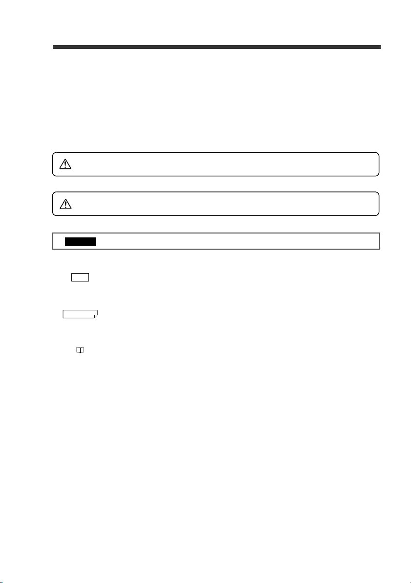
• Attach the following ferrite cores
to the connected cables.
I/O terminal: ZCAT3035-1330
USB: ZCAT2035-0930
PORT1 (code reader):
PORT2: ZCAT1325-0530
* Attach the ferrite cores on
* Above ferrite cores are manu-
• Keep the cables on the I/O terminals shorter than 30 m.
ZCAT2035-0930
both ends of the cable connected to PORT2.
factured by TDK Corporation.
UL Approval
The DV-90 Series comply with to the following UL standard and has acquired UL Certificate.
• Applicable standard UL508 Industrial Control Equipment
CAN/CSA C22.2 No.14 Industrial Control Equipment
• UL File No. E207185
• UL category NRAQ/NRAQ7
15JN Industrial Control Equipment
<Precautions>
• For the power supply of the DV-90, be sure to use a UL Listing certified power supply with the Class 2 output
as specified in the NFPA70 (NEC: National Electrical Code) of the United States.
• When wiring to the power terminal block of the DV-90 Series, be sure to use wires with range of
AWG#14 – #20, copper wire, stranded wire, and temperature rating of 60°C or more. The tightening torque
for wiring is 5 kg.cm (0.5 Nm).
• For the wires to connect to the I/O terminal block of the DV-90 Series, be sure to use wires with range of
AWG#16-#26, copper wire, stranded wire, and temperature rating of 60°C or more. The tightening torque for
wiring is 1.7Lb • in (0.2 Nm).
• Install the DV-90 Series by following the installation and wiring methods specified in this manual. Be sure to
use the DV-90 based on the product specifications outlined in this manual.
• DV-90 is for use on a flat surface of Type 1 Enclosure.
2
E DV-90-IM
Page 5

Software Licensing Agreements
Read the following licensing agreement carefully before using this software.
By using the software, you signify that you agree with the statements herein and the contract is accepted.
Licensing
1. Right of use
KEYENCE grants you the nonexclusive right to use this software in accordance with terms of this agreement.
2. Copyright
The copyright on the software and supplied documentation belongs to KEYENCE Corporation, and you hold
only the license for its use.
3. Prohibited matters
You may not copy this software and sell or distribute to a third party. However, you may copy this software for
the purpose of keeping backup copy for your personal use.
4. Indemnification
In no event shall KEYENCE be liable for any damages you and the third parties suffer from, arising from the
usage of this software.
5. Cancellation of contract
KEYENCE may terminate this agreement if you fail to comply with the terms of this agreement. In such event,
you must return the software and all copies to KEYENCE or destroy.
E DV-90-IM
3
Page 6

TRG
Content
Safety Precautions ....................................................................................................................................... 1
CE Marking and UL Conformity ................................................................................................................... 2
Software Licensing Agreements .................................................................................................................. 3
Content ........................................................................................................................................................ 4
Manual Structure .......................................................................................................................................... 9
Chapter 1 Getting Started
1-1 Checking the Package Contents..................................................................................................1-2
1-2 Overview of DV-90 Functions ....................................................................................................... 1-3
Automated Product Selection at an Assembly Workstation ....................................................................... 1-3
Preventing Mixing with Other Products at a Packaging Machine.............................................................. 1-4
Preventing Misplacement of Raw Material ................................................................................................ 1- 5
Preventing Mispackaging in a Manual Packaging Process......................................................................... 1- 6
Verifying the Assembly Instruction by Comparing with the Customer Order Sheet (Kanban)................. 1- 7
Checking the Print Quality of the Expiration Date or Manufactured Date................................................. 1- 8
Checking the Barcode Print Quality at the Printing Process ...................................................................... 1- 8
1-3 DV-90 Layout............................................................................................................................... 1-9
1-4 System Configuration and Connectable Devices...................................................................... 1-11
Chapter 2 Initial Setup of the Code Reader
2-1 Code Reader Setup Basics......................................................................................................... 2-2
How to Detect the Communication Setting Automatically ........................................................................ 2-5
2-2 Setting Procedure of the BL Series and the SR Series................................................................ 2-6
Setting Procedure Using the SetUp Software ............................................................................................. 2-6
Setting Procedure Using "Quick Setup Code"(DV-90 SetUp Software).................................................... 2-7
2-3 Read Test Procedure of the BL Series and the SR Series .......................................................... 2-8
Read Test Using the Key ...................................................................................................................... 2-8
Read Rate Test Using “Test Mode 1”......................................................................................................... 2-8
Checking the Type of the Read Barcode .................................................................................................. 2-10
Chapter 3 Connections and Mounting
3-1 I/O Terminal Connection.............................................................................................................. 3-2
I/O Terminal Pin Assignment..................................................................................................................... 3-2
Wiring the Input Terminals......................................................................................................................... 3-4
Wiring the Output Terminals (NPN Open Collector Type)........................................................................ 3-5
Wiring the Output Terminals (PNP Open Collector Type) ........................................................................ 3-6
3-2 RS-232C Interface Connection....................................................................................................3-7
Pin Assignment of the RS-232C Interface .................................................................................................. 3-7
Connecting the Code Reader....................................................................................................................... 3-8
Connecting a PC or PLC........................................................................................................................... 3-10
3-3 USB Interface Connection/Driver Installation ............................................................................ 3-13
Notes on Installing the Driver Software ................................................................................................... 3-13
Notes on Connecting the DV-90 ............................................................................................................... 3-13
Insta
lling the U
Uninstalling the USB Driver Software ..................................................................................................... 3-23
3-4 Wiring the Power Supply Terminals........................................................................................... 3-24
3-5 Mounting the DV-90...................................................................................................................3-25
4
SB Driver Software.......................................................................................................... 3-13
E DV-90-IM
Page 7

Chapter 4 Basic Functions
4-1 Verification Function ....................................................................................................................4-2
Notes on Registering Master Data .............................................................................................................. 4-3
4-2 Normal Verification ......................................................................................................................4-4
Normal Verification Function..................................................................................................................... 4-4
Setting the Normal Verification Function................................................................................................... 4-4
Presetting the Master Data (Preset Mode) .................................................................................................. 4-5
Presetting from the Desired Record Number.............................................................................................. 4-7
Deleting the Master Data ............................................................................................................................ 4-7
Working with the Normal Verification Function (Verification Mode) ...................................................... 4-8
Confirming the Master Data ....................................................................................................................... 4-9
Counter Function......................................................................................................................................... 4-9
Timing Chart for Parallel Output.............................................................................................................. 4-11
Interlock Function..................................................................................................................................... 4-11
4-3 Active Verification...................................................................................................................... 4-13
Active Verification Function .................................................................................................................... 4-13
Setting the Active Verification Function.................................................................................................. 4-13
Presetting the Master Data (Preset Mode) ............................................................................................... 4-14
Selecting the Active Record...................................................................................................................... 4-14
Working with the Active Verification Function (Verification Mode)...................................................... 4-16
4-4 Step Verification Function..........................................................................................................4-17
Step Verification Function........................................................................................................................ 4-17
Setting the Step Verification Function...................................................................................................... 4-17
Working with the Step Verification Function........................................................................................... 4-18
Timing Chart for Parallel Output.............................................................................................................. 4-20
4-5 3-Point-A Verification Function ..................................................................................................4-21
3-Point-A Verification Function............................................................................................................... 4-21
Setting the 3-Point-A Verification Function............................................................................................. 4-21
Presetting the Master Data (Preset Mode) ................................................................................................ 4-22
Working with the 3-Point-A Verification Function (Verification Mode)................................................. 4-24
Timing Chart for Parallel Output.............................................................................................................. 4-27
4-6 3-Point-B Verification Function ..................................................................................................4-28
3-Point-B Verification Function ............................................................................................................... 4-28
Setting the 3-Point-B Verification Function............................................................................................. 4-28
Presetting the Master Data (Preset Mode) ................................................................................................ 4-29
Working with the 3-Point-B Verification Function (Verification Mode)................................................. 4-29
Timing Chart for Parallel Output.............................................................................................................. 4-33
4-7 2-Point Verification Function...................................................................................................... 4-34
2-point Verification Function.................................................................................................................... 4-34
Selecting the 2-point Verification Function.............................................................................................. 4-34
Presetting the Master Data (Preset Mode) ................................................................................................ 4-35
Working with the 2-point Verification Function (Verification Mode) ..................................................... 4-36
Timing Chart of Parallel Output ............................................................................................................... 4-38
Chapter 5 Extended Functions
5-1 Reference Data Function............................................................................................................. 5-2
Reference Data Function............................................................................................................................. 5-2
Using the Reference Data Function ............................................................................................................ 5-3
5-2 Input Digit Limitation Function..................................................................................................... 5-4
E DV-90-IM
5
Page 8

Input Limitation Function ........................................................................................................................... 5-4
Setting the Input Limitation Function......................................................................................................... 5-5
5-3 Port Number Limitation Function .................................................................................................5-7
Port Number Limitation Function............................................................................................................... 5-7
Description of Port Number Limitation Function....................................................................................... 5-8
5-4 Verify Limitation Function............................................................................................................. 5-9
Verify Limitation Function ......................................................................................................................... 5-9
Date Compare Function ............................................................................................................................ 5-10
Setting the Verify Limitation Function..................................................................................................... 5-11
Working with Verify Limitation in the GS1-128...................................................................................... 5-11
Performance of 3-Point-A Verification and 3-Point-B Verification......................................................... 5-13
5-5 Read Quality Check Function....................................................................................................5-14
Read Quality Check Function ................................................................................................................... 5-14
Changing the Settings of the BL Series .................................................................................................... 5-14
Setting the “Read Quality Check Function” of the DV-90....................................................................... 5-15
Installing the Code Reader under the Same Conditions as in the BL Series ............................................ 5-16
Setting the Optimum “Quality Level ” in the DV-90 Test Mode ............................................................. 5-16
Confirming the Optimum Setting by Executing an Actual DV-90 Read Operation ................................ 5-17
5-6 Data Editing in the Preset Mode................................................................................................5-18
Data Editing in the Preset Mode ............................................................................................................... 5-18
Displaying the Master Data for Editing .................................................................................................... 5-18
Editing the Master Data Contents ............................................................................................................. 5-19
Setting the Verify Limit ............................................................................................................................ 5-21
Setting “Date Compare”............................................................................................................................ 5-22
Setting the Port Number Limitation.......................................................................................................... 5-24
Setting the Output Number ....................................................................................................................... 5-25
Chapter 6 Setting
6-1 Setting Procedures...................................................................................................................... 6-2
To Start the Setting Menu ........................................................................................................................... 6-2
To Exit the Setting Menu............................................................................................................................ 6-3
6-2 Setting Items of the DV-90...........................................................................................................6-4
Menu List .................................................................................................................................................... 6-4
Main Setting Menu...................................................................................................................................... 6-4
Verification Setting Menu........................................................................................................................... 6-6
PORT1/PORT2 Setting Menu .................................................................................................................... 6-8
I/O Settings Menu ..................................................................................................................................... 6-11
Options Setting Menu ............................................................................................................................... 6-12
Code Setting Menu.................................................................................................................................... 6-13
Initializing Settings ................................................................................................................................... 6-13
Chapter 7 How to Use the SetUp Software
7-1 Installation Procedure..................................................................................................................7-2
Installation Procedure for the SetUp Software ........................................................................................... 7-2
7-2 Overview of Operation Method.................................................................................................... 7-5
Start and Quit .............................................................................................................................................. 7-5
Menu Commands ........................................................................................................................................ 7-6
7-3 Setting Procedure........................................................................................................................7-7
Basic Settings.............................................................................................................................................. 7-7
6
E DV-90-IM
Page 9

Operation Settings....................................................................................................................................... 7-8
Master Settings.......................................................................................................................................... 7-15
About the Right-Click Menu..................................................................................................................... 7-18
7-4 Sending and Receiving the Settings ......................................................................................... 7-21
Sending the Settings.................................................................................................................................. 7-21
Receiving the Settings............................................................................................................................... 7-23
7-5 Saving/Reading/Printing the Setting Files ................................................................................. 7-25
Saving the Setting File .............................................................................................................................. 7-25
Reading the Setting File............................................................................................................................ 7-26
Printing the Setting File ............................................................................................................................ 7-27
7-6 Quick Setup Code of the DV-90 ................................................................................................7-28
Printing the Quick Setup Codes................................................................................................................ 7-28
Reading the Quick Setup Codes................................................................................................................ 7-30
7-7 Setting Procedure for the BL Series Using Quick Setup Code ................................................. 7-31
Printing the Quick Setup Codes................................................................................................................ 7-31
Reading the Quick Setup Code ................................................................................................................. 7-33
7-8 Terminal.....................................................................................................................................7-35
Receiving the Data.................................................................................................................................... 7-35
Sending Commands .................................................................................................................................. 7-36
7-9 Error Display List ....................................................................................................................... 7-39
Chapter 8 Serial Communication
8-1 Serial Communication.................................................................................................................. 8-2
Communication Form ................................................................................................................................. 8-2
Settings for Serial Communication ............................................................................................................. 8-2
8-2 Data Communication Details....................................................................................................... 8-4
Communication Protocol ............................................................................................................................ 8-4
Send Data Format........................................................................................................................................ 8-5
Type of Output Data ................................................................................................................................... 8-6
Difference in Send Data Contents Due to Verification Pattern .................................................................. 8-6
Additional Information ............................................................................................................................... 8-9
8-3 Command Communication Details............................................................................................8-10
Procedure for Using the Direct Control Commands ................................................................................. 8-10
Communication Format ............................................................................................................................ 8-10
Description of Direct Control Commands ................................................................................................ 8-11
Communication Procedure for the Setting Commands............................................................................. 8-12
Error Codes of Command Communication .............................................................................................. 8-12
Setting Command Description.................................................................................................................. 8-13
Chapter 9 PLC Link
9-1 What is a PLC Link?.....................................................................................................................9-2
What is a PLC Link?................................................................................................................................... 9-2
Supported PLCs (Series Names)................................................................................................................. 9-2
Accessible Devices ..................................................................................................................................... 9-3
9-2 Device Assignment...................................................................................................................... 9-4
DM Assignment List................................................................................................................................... 9-4
Details on DM Assignment......................................................................................................................... 9-6
9-3 Data Write Timing ......................................................................................................................9-17
9-4 Supported PLC Models .............................................................................................................
E DV-90-IM
24
9-
7
Page 10

9-5 Settings......................................................................................................................................9-26
Settings of the DV-90 ............................................................................................................................... 9-26
Settings for the KV Series......................................................................................................................... 9-27
Settings for the MELSEC Series............................................................................................................... 9-28
Settings for the SYSMAC Series.............................................................................................................. 9-30
9-6 PLC Link Communication Time ................................................................................................. 9-34
9-7 PLC Link Troubleshooting .........................................................................................................9-35
Appendix
1 Specifications ..............................................................................................................................A-2
2 Dimensions ..................................................................................................................................A-3
3 Error Messages ...........................................................................................................................A-4
4 ASCII Code Table........................................................................................................................A-5
5 Setting Item List ...........................................................................................................................A-6
6 Factory Setting List ......................................................................................................................A-9
7 PLC Program Examples ............................................................................................................A-11
KV Series .................................................................................................................................................. A-11
MELSEC Series ........................................................................................................................................ A-13
SYSMAC Series ....................................................................................................................................... A-15
8 Preset Mode Status Output .......................................................................................................A-18
9 Active Record Selection Notification .........................................................................................A-19
10 Test Barcodes ...........................................................................................................................A-20
11 Index..........................................................................................................................................A-21
8
E DV-90-IM
Page 11

Manual Structure
Chapter
1
Chapter
2
Chapter
3
Chapter
4
Chapter
5
Chapter
6
Chapter
7
Getting Started
Initial Setup of
the Code Reader
Connections
and Mounting
Basic Functions
Extended
Functions
Setting
How to Use the
Setup Software
Describes the features, functions, part names, system configuration, and the connectable devices of the DV-90.
Describes the setup procedure before connecting the code reader and using the
DV-90, and the setup and test procedures of the BL Series via the DV-90.
Describes the specifications of the parallel, serial and USB interfaces wiring the
DV-90 with other devices is also described.
Describes in detail the normal usages and performances of the functions of the
DV-90 such as “Normal Verification function” and “Step Verification function”.
Describes the useful functions of the DV-90.
The functions include “Reference Data function”, “Input Digit Specification
function”, and “Reading Quality Judgment function”.
Describes the detailed methods to set the functions of the DV-90, setting contents, and the meaning of the setting parameters and the like.
Describes the detailed procedures to set the functions of the DV-90 on a PC, and
the installation procedure of the SetUp Software.
1
2
3
4
5
6
7
Chapter
8
Chapter
9
E DV-90-IM
Serial Communication
PLC Link
Appendix
Describes the data transmission format when an external device such as a PC is
connected to the serial interface of the DV-90, and the procedure to control the
DV-90 by sending commands.
Describes the usage and the setup procedure for using the DV-90 in a PLC link.
Describes the information such as the outer dimensions of the DV-90, the default
settings at the time of shipment, and the error indications of the DV-90.
8
9
9
Page 12

MEMO
10
E DV-90-IM
Page 13

1
1
Getting Started
This chapter describes the features and configuration of a typical DV-90 setup.
1-1 Checking the Package Contents............................................. 1-2
1-2 Overview of DV-90 Functions ............................................... 1-3
1-3 DV-90 Layout ........................................................................ 1-9
1-4 System Configuration and Connectable Devices................. 1-11
1-1
Page 14
1
Note
AutoID Data Controller
DV-90
User’s Manual
Read this manual before using the system in
order to achieve maximum performance.
Keep this manual in a safe place for future
reference.
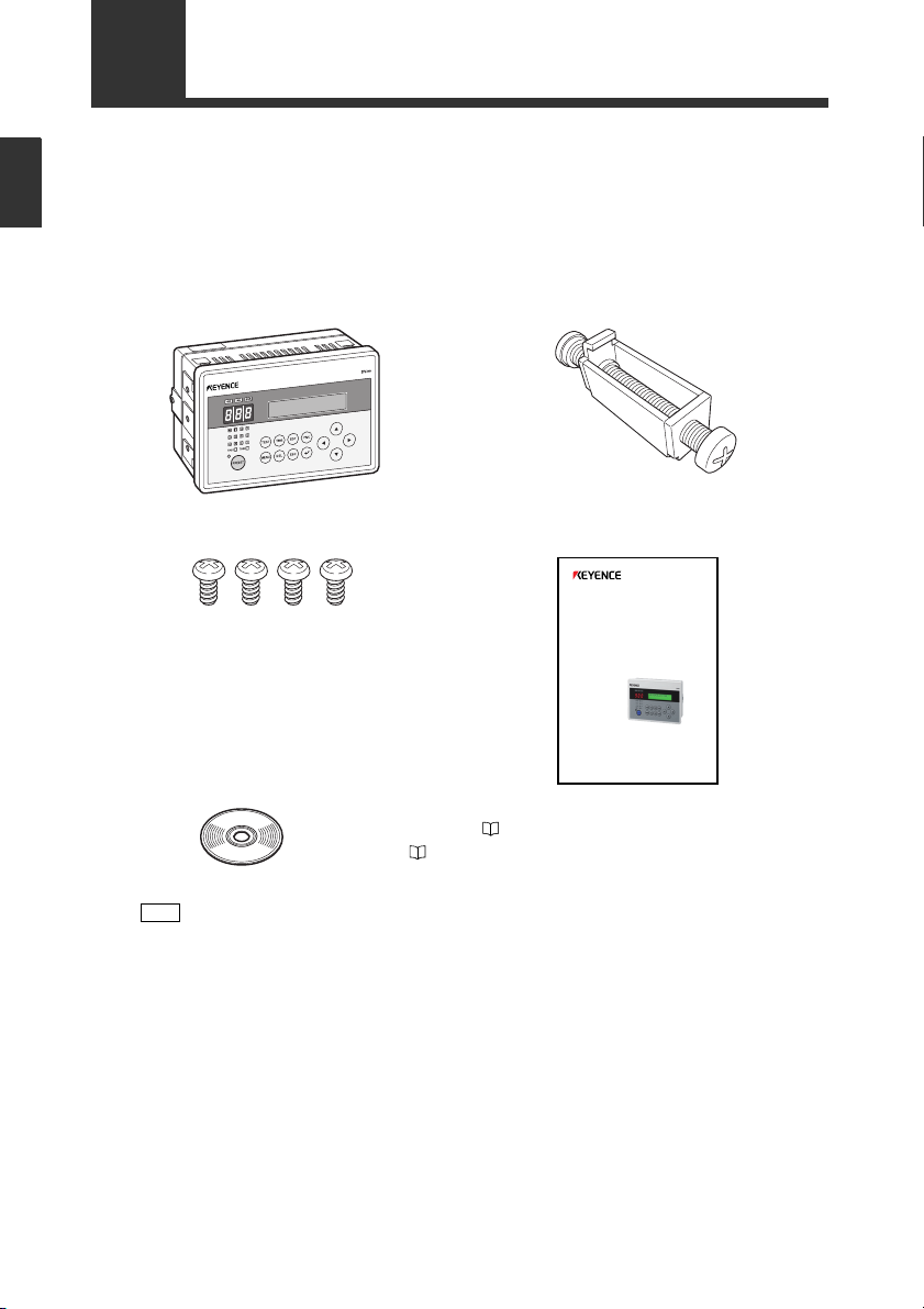
CD-ROM…1
Mounting screw (M4 tapping screw)
…4 User’s Manual…1
DV-90NE main unit
…1 Panel mounting bracket…4
Getting Started
1-1
Checking the Package Contents
The package contains the following equipment and accessories.
Before using the DV-90, check that the following items are all included.
DV-90NE (NPN open collector output type)
Refer to the User’s Manual of the BL Series.
DV-90PE (PNP open collector output type)
DV-90PE main unit ....................................1
1-2
Panel mounting bracket .............................4
Mounting screw (M4 tapping screw) ......... 4
CD-ROM ................................................... 1
User’s Manual ............................................1
(Included software)
• DV-90 SetUp Software ( Refer to 7-2)
• USB driver ( Refer to 3-13)
• BL Series SetUp Software
E DV-90-IM
Page 15
1-2
Note
Overview of DV-90 Functions
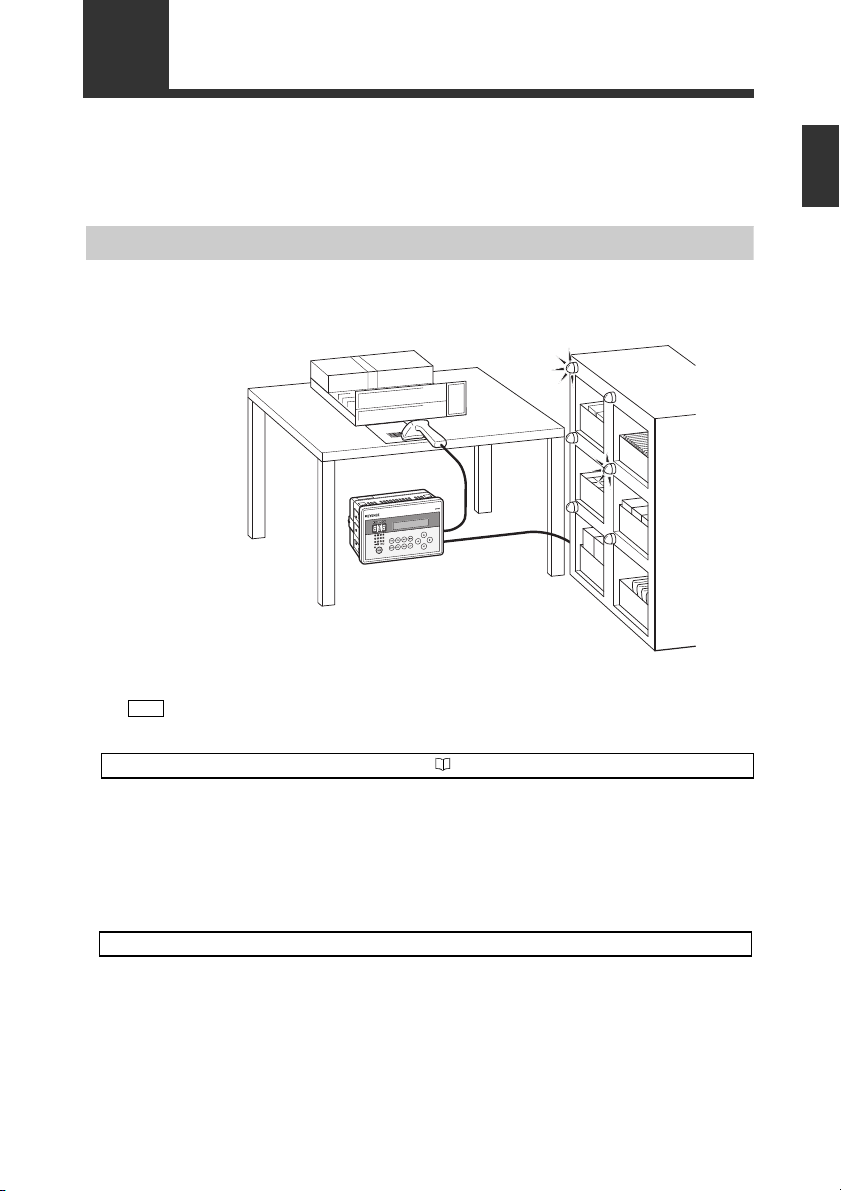
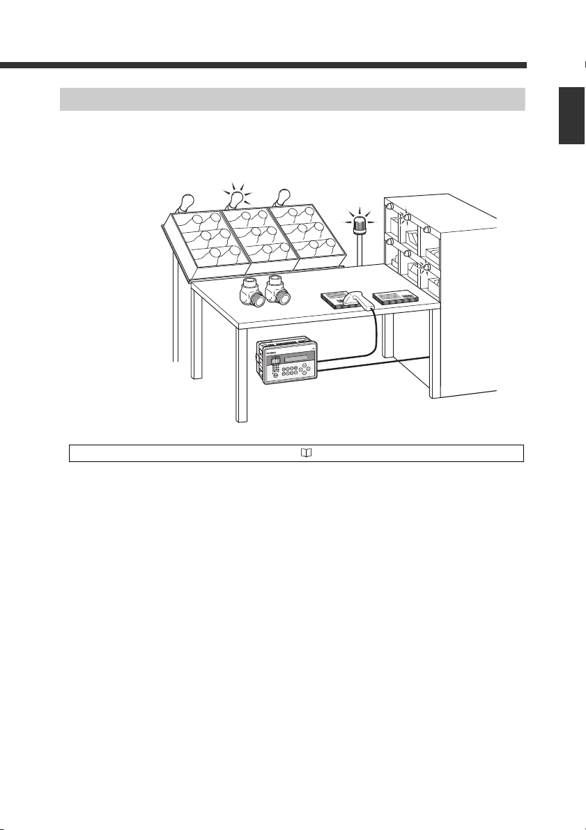
Automated Product Selection at an Assembly Workstation
By reading the barcode attached to an assembly instruction sheet or a product in a high-mix lowvolume production line, the lamp on the shelf which contains the part to be assembled illuminates.
By assembling the part stored on the illuminated shelf, assembly errors can be reduced.
1
Getting Started
The figure above is an example using a handheld reader. A fixed type reader can also be
used.
Use the “Normal Verification” function. Refer to 4-4
Up to 900 presets be registered beforehand in the DV-90 as master data. The data read with the barcode reader is compared with the master data, and the corresponding preset number is output in parallel transmission.
In the above figure, the barcode on the assembly instruction sheet is preset in the DV-90. By connecting the parallel output after verification to a device such as a PLC, the corresponding lamp on
the part shelf illuminates, thus preventing assembly errors.
Other uses
• Commanding operations to robots
By connecting the parallel output to a PLC for controlling a robot, the DV-90 can command the
robot to perform specified operations.
• Switching the setting values of devices
The parallel output allows the setting values of the connected devices such as a weight checker to
be changed automatically.
E DV-90-IM
1-3
Page 16
1
Getting Started
1-2 Overview of DV-90 Functions
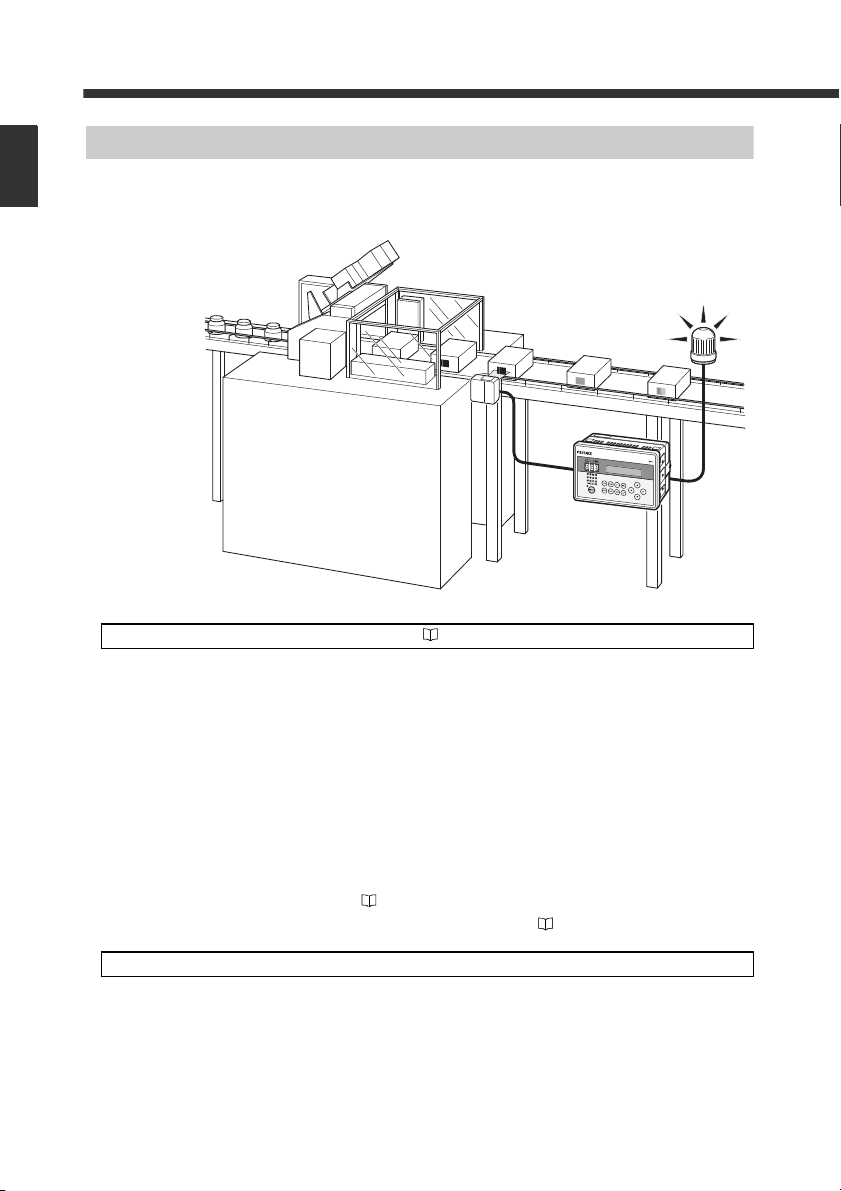
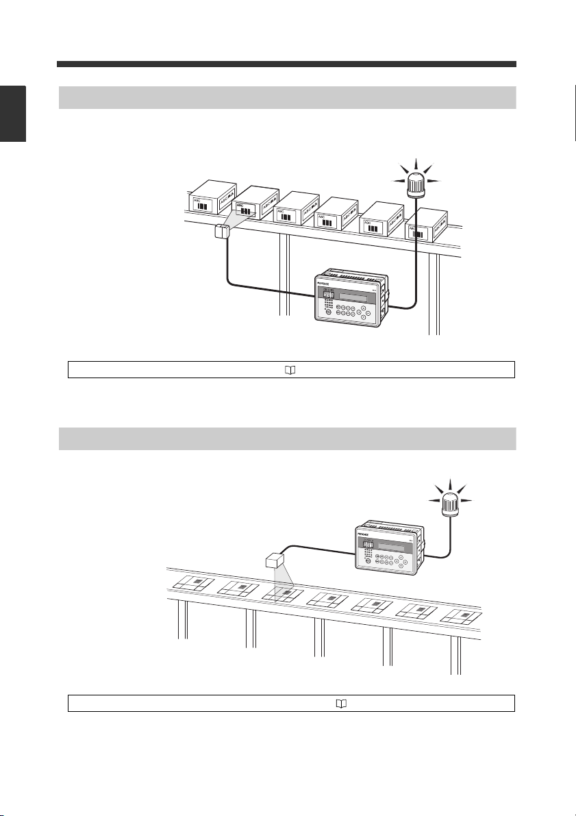
Preventing Mixing with Other Products at a Packaging Machine
By reading the barcode printed on carton cases or cardboard cases at a packaging machine (carton
packing machine or cardboard caser), the mispackaging of products in the wrong box can be prevented.
Use the “Active Verification” function. Refer to 4-13
Up to 900 presets can be registered beforehand in the DV-90 as master data. The user selects a preset (the “active” record) for the particular line. When a product is scanned with a code reader, the
data is compared to the active preset. A match turns on the OK output. Otherwise, the NG output is
activated.
In the above figure, the barcodes printed on all the carton cases to be used are preset, and the carton
case to be used for the next packaging is selected from among them. If the barcode of the selected
carton case and the actually read barcode do not match, a lamp or buzzer notifies the operator that a
wrong carton case is present.
Other uses
1-4
An active record can be selected by any of the following methods:
• The DV-90 front panel buttons
• Reading the barcode you want to select
• From a PLC (PLC link ⇒ Refer to 9-4)
• Sending commands from a PC (Serial communication ⇒ Refer to 8-11)
• Preventing mixing with other products at a labeling machine
Whether the correct label is attached to the product on a labeling machine can be checked.
• Preventing mixing of other products at a filling machine
On a filling machine that fills beverages, cosmetic creams, or seasonings, whether the content is
filled in the correct container can be checked.
E DV-90-IM
Page 17
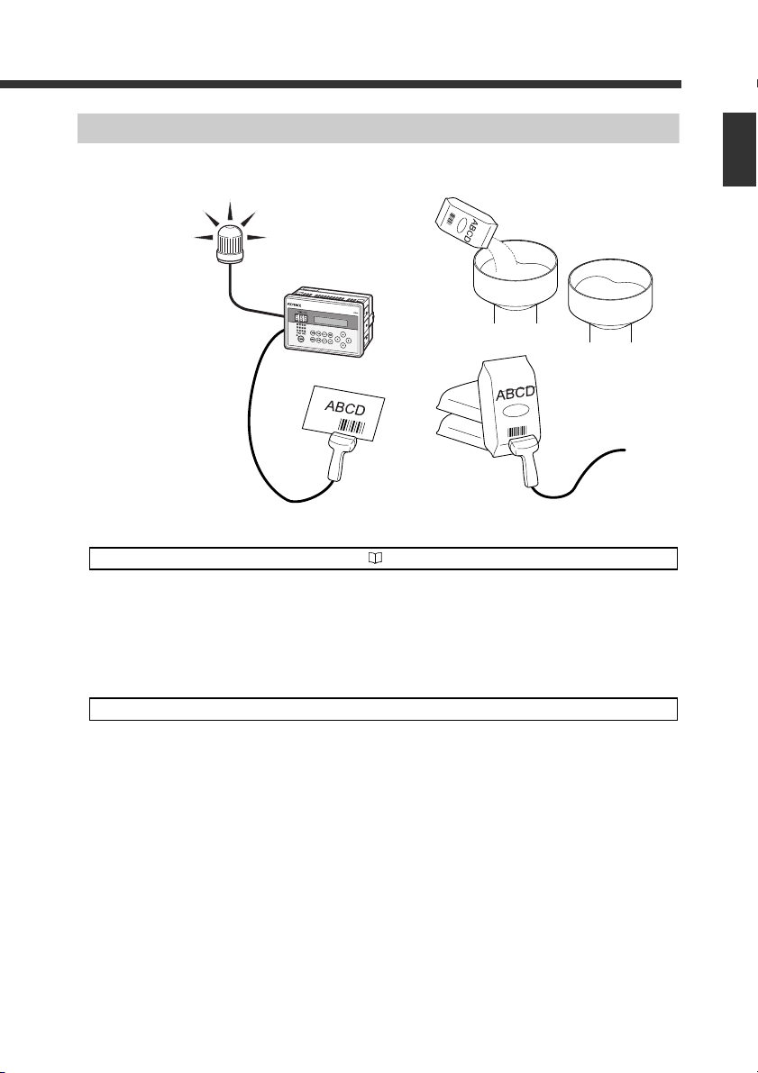
Preventing Misplacement of Raw Material
Use the “Step Verification” function. Refer to 4-17
Reading the barcodes on a batch instruction sheet and raw material package before adding the raw
material ensures product uniformity.
The barcode data initially read and the data read next are compared, and Match/No match (OK/NG)
is output.
In the above figure, the barcode on the batch sheet is read first, and then the barcode on the material
is read. If they do not match, a lamp or buzzer notifies the operator.
1-2 Overview of DV-90 Functions
1
Getting Started
Other uses
E DV-90-IM
• Preventing mixing of chemical bottles on a semiconductor production machine
Checking whether the barcodes on the chemical bottle before replacement and on the new
chemical bottle after replacement prevents potentinally dangerous or damaging mix-ups from
occurring.
1-5
Page 18
1
Getting Started
1-2 Overview of DV-90 Functions
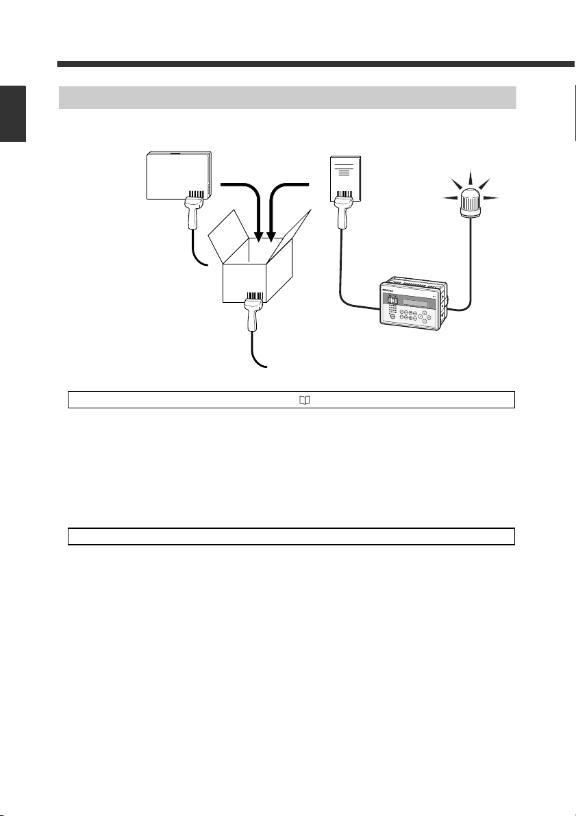
Preventing Mispackaging in a Manual Packaging Process
Reading the barcodes on the packaging case, product, and user’s manual in a manual packaging
process prevents the packaging of a wrong product or user’s manual.
Use the “3 Points Verification” function. Refer to 4-21
By bundling three barcode data as one set, up to 900 sets of master data can be registered (preset) in
the DV-90. If the combination of the three read barcodes is correct, an OK output turns on. Otherwise, an NG output turns on.
In the above figure, all the combinations of the barcodes on the packaging case, product, and user’s
manual are preset. The operator reads the barcodes in the order of the packaging case > product >
user’s manual. If the barcode of the wrong product or user’s manual is read, a lamp or buzzer notifies the operator.
Other uses
1-6
• Preventing misplacement of chip reels on a chip mounting machine
Misplacement of the chip reel can be prevented by checking whether the barcode on the old chip
reel, the one on the new chip reel, and the one on the placement location all match.
E DV-90-IM
Page 19
1-2 Overview of DV-90 Functions
Verifying the Assembly Instruction by Comparing with the Customer Order Sheet (Kanban)
In the process of assembling products such as automobile parts, by reading the barcodes on the
assembly instruction, product, and the customer order sheet (Kanban), the part to be assembled can
be specified and also you can check whether the assembly instruction and the customer order sheet
(Kanban) match.
1
Getting Started
Use the “Picking Verification” function. Refer to 4-28
By bundling three barcode data as one set, up to 900 sets of master data can be registered (preset) in
the DV-90. Three barcodes are read in a row, and the output No. corresponding to the master data
that matches each of one of the barcodes is output in parallel transmission.
Eventually, when all the preset barcodes in a set match the master data, an OK output turns on. Otherwise, an NG output turns on.
Let’s look at the example shown above.
First of all, preset all the combinations of the barcode data of the assembly instructions, products,
and the customer order sheet (Kanban) prepared for today’s production.
When the assembly operator reads the barcode on the assembly instruction, the lamp on the shelf
that contains the products to be manufactured illuminates. The operator places the indicated product
on the workbench. Then, when the operator reads the barcode on the product, the lamp on the shelf
that contains the part to be assembled on that product illuminates. The operator can then take the
indicated part and assemble it on the product.
Finally, the operator reads the barcode (Kanban) on the customer order sheet. If the assembly operation has been done properly, an OK output turns on. Otherwise, an NG output turns on.
E DV-90-IM
1-7
Page 20
1
Getting Started
1-2 Overview of DV-90 Functions
Checking the Print Quality of the Expiration Date or Manufactured Date
Whether the expiration date or manufactured date in the barcode that includes it is correct can be
checked.
Use the “Date Comparison” function. Refer to 5-10
The DV-90 extracts the data that indicates the expiration date in the barcode, and compares it with
the calendar in the DV-90. If the date is incorrect, or the date has expired, an NG output turns on.
Checking the Barcode Print Quality at the Printing Process
The printing quality of barcodes can be checked while they are being printed.
Use the “Reading Quality Judgment” function. Refer to 5-14
The reading stability of the barcode reader connected to the DV-90 can be checked.
Set the reference value of the reading stability. When the actual reading stability drops below the
reference value, “Reading Quality Judgment Output (QUALITY)” turns on. This allows you to
determine the reading stability.
1-8
E DV-90-IM
Page 21
1-3
DV-90
OK NG
TEST TRG EDIT FNC
MENU
PRESET
DEL ESC
12 11 10 9
8765
4
TRG1 TRG2
321
ERR
➁
➃
➄
➀
➂
➅
MENU
TEST
DEL
ESC
EDIT
FNC
TRG
Panel side
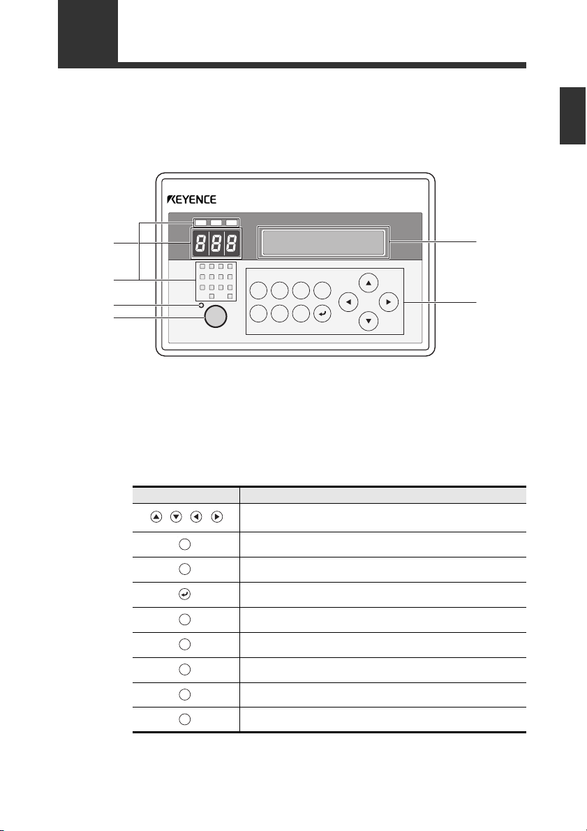
DV-90 Layout
1
Getting Started
➀ Record No. indicator LEDs ........... Display the record No. being registered, matched record
No., and the reading rate of the code reader.
➁ Parallel input/output LEDs ............ Display the ON/OFF status of the parallel input/output.
➂ LCD display ....................................... Displays the read data, menu settings and error
messages.
➃ Preset LED ......................................... Illuminates during the preset mode.
➄ Preset key .......................................... Used to register master data (preset).
➅ Operation keys ................................. Used for adjusting DV-90 settings.
E DV-90-IM
Key Usage
Used for selecting the setting items or record No. displayed in the LCD
display.
Used for changing the settings of the DV-90.
Used for the read test, code type check, and reading quality setting.
Used for confirming the setting items and executing the functions.
Used for deleting master data, and deleting a character from the input data.
Used for canceling a menu and the like.
Used for correcting the master data.
Used for executing a special function.
Performs a trigger input to the code reader by key operation.
1-9
Page 22
1
1
2
3
4
5
6
7
TRG 1
TRG 2
COM 1
+24V
0V
+24V
0V
8
9
10
11
12
13
14
8
9
10
11
12
13
14
REMOTE
COM2
UNLOCK
COM3
OK
NO
COM4
15
16
17
18
19
20
21
READ_ERR
QUALITY
COM5
OUT1
OUT2
OUT3
OUT4
22 OUT5
23
24
25
26
27
28
29
OUT6
OUT7
OUT8
OUT9
OUT10
OUT11
OUT12
30 COM6
PORT 2 PORT 1
15
16
17
18
19
20
21
22
23
24
25
26
27
28
29
30
1
2
3
4
5
6
7
➇
➆
➉➈
11
11
Getting Started
1-3 DV-90 Layout
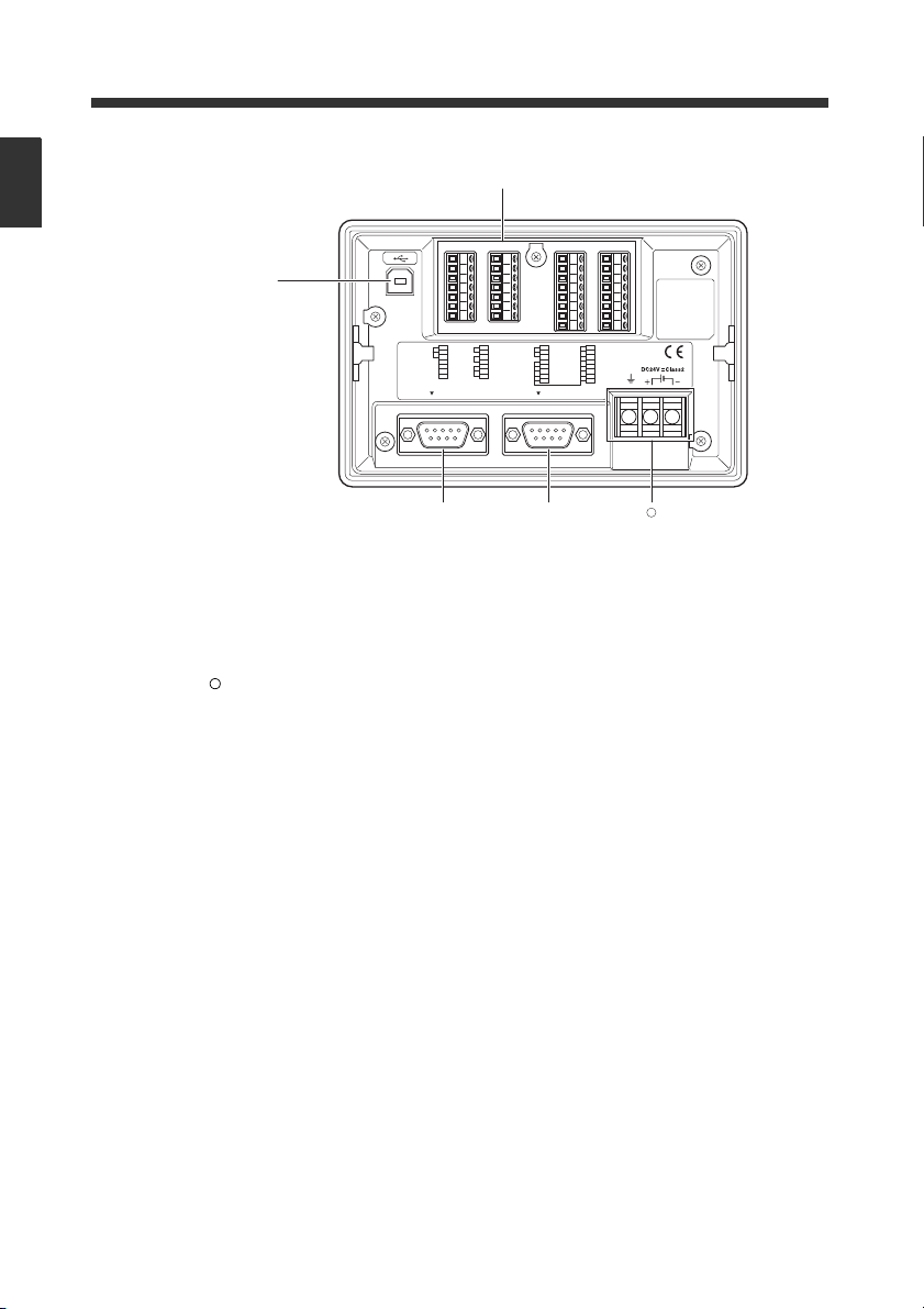
Terminal side
➆ USB port ............................................ Connects to the USB port on a PC.
➇ I/O terminal block ............................ Consists of parallel input and output terminals. The
trigger input corresponding to the connected BL Series
is connected here.
➈ RS-232C (PORT1) ........................... Connects to a code reader.
➉ RS-232C (PORT2) ............................ Connects to a PC, code reader or other approved device.
Power terminal ................................. Connects to a 24V DC power supply unit.
E DV-90-IM
1-10
Page 23
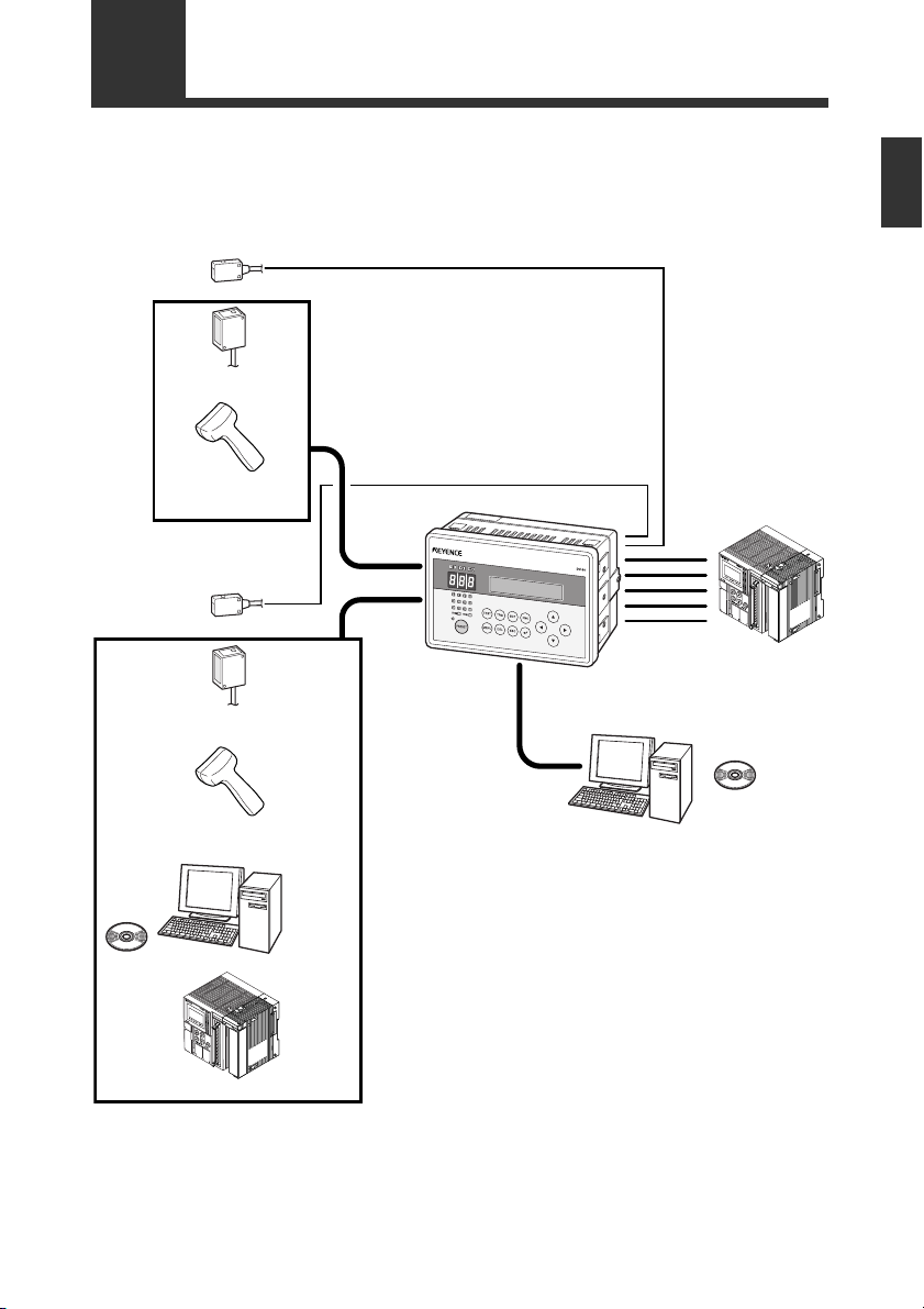
1-4
KV-B16XA
KV-B16XA
Photoelectric switch
Barcode
fixed reader (
∗5)
Barcode
handheld reader (
∗5)
DV-90
PORT1(
∗1)
PORT1(
∗2)
Photoelectric switch
Barcode/2D code
fixed reader (
∗5)
Barcode/2D code
handheld reader (
∗5)
USB(
∗3)
I/O(
∗4)
PLC
PC
SetUp
Software
(
∗6)
PCSetUp
Software
(
∗6)
RS-232C
RS-232C
PLC (
∗7)
The DV-90 can be used with the following devices.
Numbers in parentheses ( ) are described on the following page.
System Configuration and Connectable Devices
1
Getting Started
E DV-90-IM
1-11
Page 24
1-4 System Configuration and Connectable Devices
∗ 1 PORT1 can connect a barcode reader.
1
Getting Started
PORT2 can connect either a barcode reader, PC or PLC.
∗ 2
∗ 3 USB can connect a PC.
The supported operating systems are Windows 8/7/Vista/XP/2000.
∗ 4 The I/O terminal has 4 input pins and 16 output pins.
The NPN open collector output type (DV-90NE) and the PNP open collector output type
(DV-90PE) are available for output.
∗ 5 The barcode readers that can be directly connected to PORT1 or PORT2 are the BL-700/600/
180 Series, HR-40RK/50RK, and BL-210RK/N70RKE. For the BL-1300 Series, SR Series,
TL-800/70R, and HR-30R/HR-UC51, a connector cable must be prepared separately.
The barcode reader directly connected to PORT1 or PORT2 are powered from the
connected port. The maximum +5V DC power current that can be supplied to PORT1
and PORT2 is 1100 mA in total. Ensure that the power consumption of the connected
barcode reader stays under this limit.
However, when the ambient temperature exceeds 40 °C, the maximum power current
that can be supplied is 850 mA.
∗ 6 The SetUp Software is used when changing the internal settings of the DV-90.
The settings can be changed on the PC that is connected to USB or PORT2.
∗ 7 In the communication with a PLC, non-procedural communication (An RS-232C unit that can
establish non-procedural communication is required on the PLC side. Consult with the PLC
manufacturer.) or communication by the dedicated protocol for the PLC manufacturer (PLC
link) is available.
The following models of PLC are available for PLC link.
Keyence KV Series
Mitsubishi Electric MELSEC Series
Omron SYSMAC Series
Connectable combinations
Since PORT1, PORT2, and USB function independently, the connecting devices can be opted for
independently as well.
The following list shows the connectable combinations.
1-12
PORT1 PORT2 USB
Code reader - -
Code reader PC -
Code reader - PC
Code reader PC PC
Code reader PLC -
Code reader PLC PC
Code reader Code reader -
Code reader Code reader PC
E DV-90-IM
Page 25

2
2
Initial Setup of the Code Reader
This chapter describes the basic setup for connecting a code reader to the DV-90.
2-1 Code Reader Setup Basics..................................................... 2-2
2-2 Setting Procedure of the BL Series and the SR Series .......... 2-6
2-3 Read Test Procedure of the BL Series and the SR Series...... 2-8
2-1
Page 26

2-1 Code Reader Setup Basics
Reference
Note
MENU
ESC
This section describes the preparation flow before using the DV-90.
2
Initial Setup of the Code Reader
1 In the settings of the DV-90, select "CR1 Type" in "Main".
Specify the type according to the code reader to connect.
Code reader model name Type
BL-1300/700/600/180 Series Type A
HR-50RK/40RK/UC51
BL-N70RKE/N9R
TL-800, TL-70R Type C
BL-210RK Type D
SR Series, HR-100 Type E
Other code readers Others
(Setting procedure)
(1) Press the key for one second to enter the setting mode.
(2) Select “1 Main” and press the key.
(3) Press the key twice to display “03 CR1 Type”.
(4) Press the key to display a cursor.
(5) Select “TypeA,B,C,D,E, or Others”, and press the key.
(6) Press the key twice to exit the setting mode.
By specifying the code reader type, the settings such as the default values of the communication setting of the DV-90 and pin assignment of PORT1 are modified to suit the specified
code reader.
Type B
2 Configure the settings of the connecting code reader as follows.
If the code reader is at default, no setting change is required.
<BL-1300/700/600/180 Series, HR-50RK/40RK/UC51, BL-210RK/N70RKE/N9R>
• Baud rate : 9600 bits/s • Data length : 7 bits
• Parity : Even • Stop bit length : 1 bit
• Header : None • Terminator : CR or CR LF
• Communication protocol : No hand shaking
<TL-70R>
• Baud rate : 9600 bits/s • Data length : 8 bits
• Parity : None • Stop bit length : 1 bit
• Header : None • Terminator : CR or CR LF
• Communication protocol : No hand shaking
<SR Series, HR-100>
• Baud rate : 115200 bits/s • Data length : 8 bits
• Parity : Even • Stop bit length : 1 bit
• Header : None • Terminator : CR
• Communication protocol : No hand shaking
• If the setting cannot be changed on the code reader side, adjust the DV-90 settings for
“PORT1” in the setting mode of the DV-90. (
• If you are using the BL-1300/700/600/180 and the code reader setting cannot be checked, the
DV-90 can detect it automatically.
Refer to page 2-5 for automatic detection.
Refer to 6-8.)
2-2
E DV-90-IM
Page 27
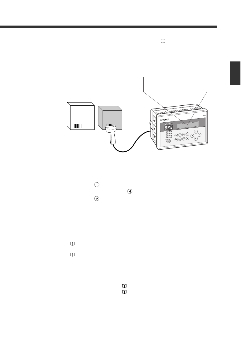
1234567890
TRG
2-1 Code Reader Setup Basics
3 Connect the code reader to PORT1 of the DV-90. ⇒ Refer to 3-8.
Turn off the power of the DV-90 when connecting the code reader.
4 Read the data with the code reader, and confirm that the data is displayed on the
LCD of the DV-90.
• If you are using the BL-1300/700/600 or the SR Series, the data can be read by gently pressing the [TEST] switch on the DV-90 once.
• If you are using the BL-180, perform the following key operations on the DV-90. (The same
operations are valid on the BL-1300/700/600 and the SR-600/500.)
(1) Press the key on the DV-90.
(2) Select “CR1” by pressing the key on the DV-90.
(3) Press the key on the DV-90 and reading starts.
2
Initial Setup of the Code Reader
5 Change the code reader settings
(such as the type of barcode to read).
• For the HR-50RK/40RK/UC51, BL-210RK/N70RK/N9R, and TL-800/70R, refer to the
respective manuals to change the settings.
• For the BL-700/600/180 Series, configure the settings on the BL SetUp Software.
⇒
Refer to “BL Series User’s Manual”.
• The settings are made on Auto ID Navigator for the BL-1300 and the SR-600/500.
⇒
Refer to “BL-1300 Series and SR Series User's Manual”.
6 According to the purpose of use, change the settings of the DV-90.
The settings of the DV-90 can be changed in the following methods.
• Key operations on the DV-90 ⇒
• DV-90 SetUp Software ⇒
E DV-90-IM
Refer to 6-1.
Refer to 7-1.
2-3
Page 28
2-1 Code Reader Setup Basics
7 Wire the trigger input (input to starting reading). ⇒ Refer to 3-4.
• If a hand-held reader is connected, no wiring is required.
• For the BL-1300/700/600/180 Series and the SR-600/500, wire the trigger input to the DV-
90.
2
Initial Setup of the Code Reader
8 Wire the I/O terminals. ⇒ Refer to 3-2.
9 If you want to communicate with a device such as a PC or a PLC, connect the
DV-90 to the device. ⇒ Refer to 3-10.
For the communication control and operation methods according to the connected device, refer
to the following pages.
• PC (serial communication) ⇒ Refer to 8-1.
• PLC (PLC link) ⇒ Refer to 9-1.
10 Use the DV-90 and confirm its operation is correct.
The DV-90 setup and connections is complete.
2-4
E DV-90-IM
Page 29
1 Main
2 Verify
MENU
3 PORT1
4 PORT2
0:Manual
01 Comm.config
1:Auto
01 Comm.config
011 Auto Config
Cancel-ESC
011 Auto Config
:9600 /7e1
011 Auto Config
:???????
×
ESC
2-1 Code Reader Setup Basics
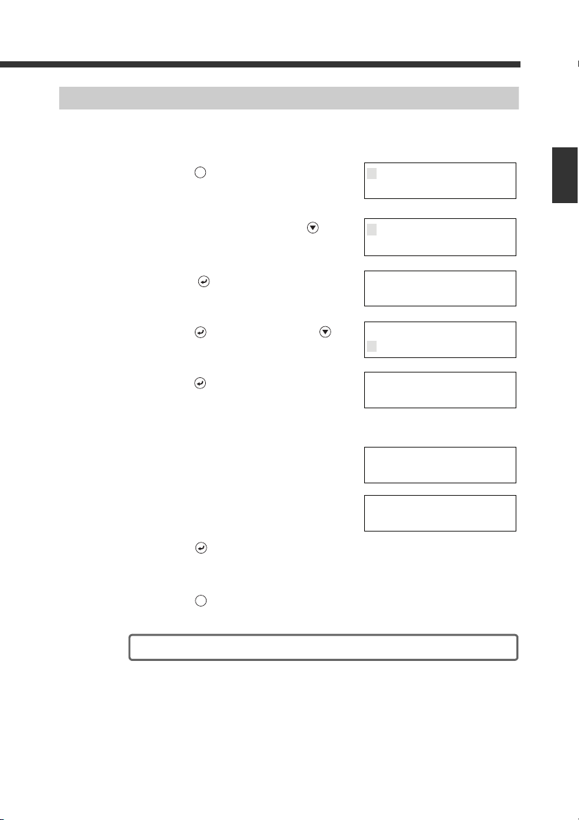
How to Detect the Communication Setting Automatically
When the communication setting of the connected BL-1300/700/600/500/180 Series cannot be
checked, you can have the DV-90 detect it automatically.
Follow the steps below.
1 Press the key for a second.
The display enters the setting mode.
2 Select “3 PORT1” by pressing the key
twice.
3 Press the key.
4 Press the key, and then press the key.
5 Press the key and the automatic detection
starts.
The screen to the right is displayed during the auto detection.
6 The result is displayed when the detection is
completed.
When the detection has failed, the screen to the right
is displayed.
7 Press the key and the detected setting is
confirmed.
2
Initial Setup of the Code Reader
E DV-90-IM
8 Press the key twice to exit the setting mode.
The automatic detection is completed.
2-5
Page 30
2-2
Note
PC Direct
*CR1<>
TEST
PC Direct
PORT2<>USB*
When changing the settings of theBL-1300/700/600/500/180 Series or the SR-600/500 Series, use the SetUp Software dedicated to the BL Series or AutoID Navigator. This section describes its procedure.
Setting Procedure of the BL Series and the SR Series
2
Initial Setup of the Code Reader
Setting Procedure Using the SetUp Software
1 Perform step 1 though 4 described in “2-1 Flow of Connections and Settings”.
2 Connect the PC to the USB port or PORT2 of the DV-90.
• To connect the PC to the USB port, the USB driver software for the DV-90 should be
installed. ⇒ Refer to 3-13.
• When connecting the PC to PORT2 ⇒ Refer to 3-10.
3 Start the SetUp Software and change the settings as desired.
For the operation procedures of the BL SetUp Software and AutoID Navigator, refer to the BL
Series and SR Series User's Manuals.
4 Configure the DV-90 to establish direct communication between the code reader
and the PC.
(1) Pressing the key on the DV-90 three times
displays “Test Mode 3 PC Direct” for a second,
and the screen to the right is displayed.
If “PORT2 Unit” is set to “Code Reader”, the
CR1/CR2 selection screen appears. Select the one
with which you want to communicate, and press
the key.
(2) Select the port of the DV-90 to which the PC is
connected.
• When connected to USB
Press .
• When connected to PORT2
Press .
(3) Press the key.
2-6
“PORT2” is not displayed at (2) if “PORT2 Unit” is not set to “PC”.
E DV-90-IM
Page 31

Note
12 11 10 9
8765
4
TRG1 TRG2
321
< SEND
>OK
ESC
2-2 Setting Procedure of the BL Series and the SR Series
5 Configure the PC communication conditions on the setup software.
BL SetUp Software
Configure “PC Port Setting” as follows:
• When connected to USB
• Port : Specify the port No. of the USB.
• Baud rate : 115200 bits/s
• Data length : 8 bits
• Parity : Even
• Stop bit length : 1 bit
• When connected to PORT2
• Port : Specify the port No. of the RS-232C.
• Baud rate : 9600 bits/s
• Data length : 7 bits
• Parity : Even
• Stop bit length : 1 bit
AutoID Navigator
Configure “Option” as follows:
• When connected to USB
• Port : Specify the port No. of the USB.
* If the port settings are correct, other settings are not required.
• When connected to PORT2
• Port : Specify the port No. of the RS-232C.
• Connection method : Check DV-90 PC Direct.
• Baud rate : 115200 bits/s
• Data length : 8 bits
• Parity : Even
• Stop bit length : 1 bit
If the settings cannot be sent due to the processing speed of the computer, change the
timeout to its maximum value (60 sec).
2
Initial Setup of the Code Reader
Setting Procedure Using "Quick Setup Code"(DV-90 SetUp Software)
E DV-90-IM
6 Send the settings from the setup software.
The parallel input/output LEDs on the DV-90 illuminate
one by one in sequence during communication. The
commands being communicated are displayed on the
LCD.
7 Press the key on the DV-90 to exit “PC
Direct”.
The settings are completed.
The settings of the code reader can also be configured by reading the barcode on the “Code
Reader "Quick Setup Code" printed from the DV-90 SetUp Software (BL-700/600/500/180).
⇒ Refer to 7-31.
2-7
Page 32

2-3
Note
TRG
Input Trigger
*CR1<>
TRG
1234567890
Read Error (CR1)
TRG
Reader Test
>
TEST
This section describes how to perform the read test for the BL Series and the SR Series.
Read Test Procedure of the BL Series and the SR Series
2
Initial Setup of the Code Reader
The read test described here is applicable to the BL-1300/700/600/180 and the SR-600/500
Series code readers.
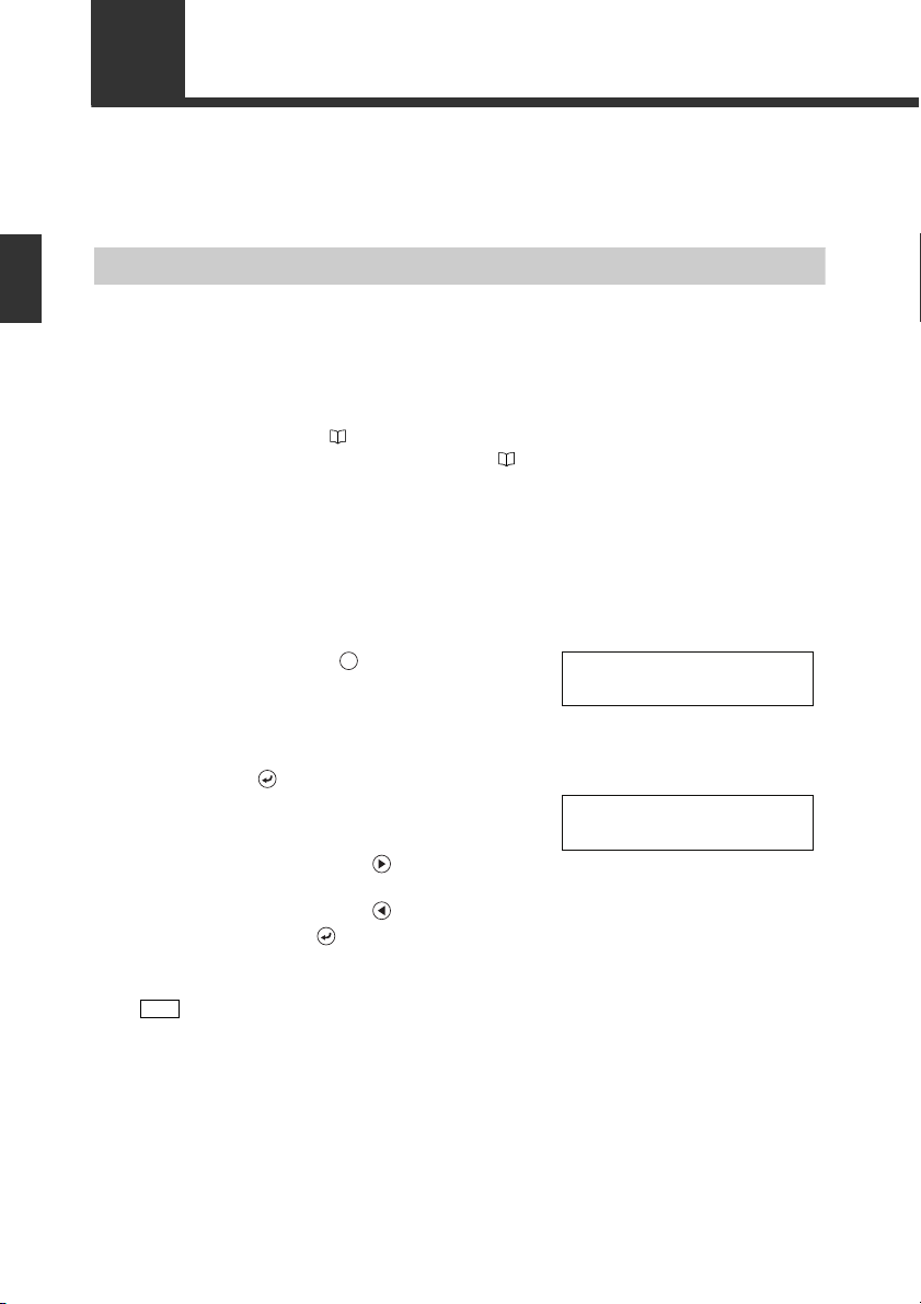
Read Test Using the Key
The following procedure performs the read test using the key.
The same operation can be performed by turning on/off the trigger input.
1 Press the key on the DV-90.
2 Select “CR1” by pressing the key on the DV-90.
3 Press the key on the DV-90 and the read-
ing starts.
When a code is read, the data is compared with the
master data, and displayed on the screen.
When the data cannot be read the reading results in an
error, and the screen to the right is displayed.
Repeat steps 1 through 3.
The read test using the key is completed.
Read Rate Test Using “Test Mode 1”
2-8
The following procedure performs a read rate test in the test mode.
The reading rate test mode can be activated by sending commands to the BL Series or the SR
Series from the DV-90.
1 Pressing the key on the DV-90 displays
“Test Mode 1 Reader Test” for a second, and
the screen to the right is displayed.
E DV-90-IM
Page 33

TEST1
*CR1<>
FNC
TEST1
*CR1<>
TEST1
>1234567890:60%
2-3 Read Test Procedure of the BL Series and the SR Series
2 Press the key on the DV-90 and the com-
mand to be sent to the BL Series or the SR
Series is displayed.
Press the or key to select either one of the following items.
BL-700/600/180 BL-1300 SR-600/500
Starts the reading rate test
TEST1
mode.
Starts the tact measurement
TEST2
test mode.
TEST3 –
QUIT Quits the test mode. Quits the test mode. Quits the test mode. (Offline)
Starts the online test mode
#TEST1
(BL700/600 only).
#TEST2 ––
#TEST3 ––
Quits the online test mode
#QUIT
(BL700/600 only).
LON Starts reading. Starts reading. Starts reading.
LOFF Quits reading. Quits reading. Quits reading.
Refer to the user’s manual of the BL Series and the SR Series for the details of these functions.
Starts the reading rate test
mode.
Starts the tact measurement
test mode.
Starts the code position
measurement test mode.
Starts the online test mode.
Quits the online test mode. Quits the test mode (Online)
Starts the reading rate test
mode. (Offline)
Starts the tact measurement
test mode. (Offline)
Starts the code position
measurement test mode.
(Offline)
Starts the reading rate test
mode. (Online)
Starts the tact measurement
test mode. (Online)
Starts the tact measurement
test mode. (Online)
3 When using the reading rate test mode,
select “TEST1” with the or key.
4 Press the key on the DV-90.
The code is read, and then the data and reading rate
are displayed.
The reading rate is displayed on the Record No. indicator LEDs.
2
Initial Setup of the Code Reader
E DV-90-IM
2-9
Page 34

QUIT
>1234567890:60%
FNC
ESC
Code Check
>
TEST
Code type
Number of digits
JAN:13
> 1234567890ABC
TRG
ESC
2-3 Read Test Procedure of the BL Series and the SR Series
5 To exit the reading rate test mode, press the
key on the DV-90, select “QUIT” with the
or key, and then press the key.
2
Initial Setup of the Code Reader
6 Press the key to exit the test mode.
The read test is completed.
Checking the Type of the Read Barcode
Pressing the key on the DV-90 twice dis-
1
plays “Test Mode 2 Code Check” for a second, and the screen to the right is displayed.
Press the key. Press the “TEST” button
2
on the BL Series or the SR Series as a code
passes underneath the reader.
The screen displays the type, the number of digits,
and the content of the read code.
3 Press the key to exit the test mode.
The code check in the test mode is completed.
2-10
E DV-90-IM
Page 35

3
3
Connections and Mounting
This chapter describes the connection of the devices and mounting procedure of the
DV-90.
3-1 I/O Terminal Connection ....................................................... 3-2
3-2 RS-232C Interface Connection .............................................. 3-7
3-3 USB Interface Connection/Driver Installation..................... 3-13
3-4 Wiring the Power Supply Terminals.................................... 3-24
3-5 Mounting the DV-90 ............................................................ 3-25
E DV-90-IM
3-1
Page 36

3-1 I/O Terminal Connection
8
9
10
11
12
13
14
15
16
17
18
19
20
21
22
23
24
25
26
27
28
29
30
1
2
3
4
5
6
7
I/O Terminal Pin Assignment
3
Connections and Mounting
No. Label Name No. Label Name
1 TRG1 Trigger input 1 15 READ_ERR Read error output
2 TRG2 Trigger input 2 16 QUALITY Read quality judgment output
3 COM1 Trigger input common 17 COM5
4 +24V 24V DC power output 1 (+) 18 OUT1
5 0 V 24V DC power output 1 (-) 19 OUT2
6 +24V 24V DC power output 2 (+) 20 OUT3
7 0 V 24V DC power output 2 (-) 21 OUT4
8 REMOTE Remote input 22 OUT5
9 COM2 Remote input common 23 OUT6
10 UNLOCK Unlock input 24 OUT7
11 COM3 Unlock input common 25 OUT8
12 OK Verify OK output 26 OUT9
13 NG Verify NG output 27 OUT10
14 COM4 Verify OK/NG output common 28 OUT11
29 OUT12
30 COM6 Verify result output common
Read error/Read quality judgment
output common
Verify result output
3-2
E DV-90-IM
Page 37

Connecting the cable
Connect the cable by using a screwdriver as shown below. (Tightening torque: 0.2 Nm)
3-1 I/O Terminal Connection
3
Connections and Mounting
E DV-90-IM
3-3
Page 38

3-1 I/O Terminal Connection
PRESET
ESC
10 to 26 VDC
* The COM terminals are insulated from each other.
* The 24V DC power output of th e terminal block can be
used for the input power.
Input
Internal circuit
• Input rated voltage : 1 0 to 26 V DC
• Maximum OFF current : 1.0 mA
(NPN)
Wiring the Input Terminals
Pin label Name Description
TRG1 Trigger input 1 Inputs a trigger signal to the code reader connected to
TRG2 Trigger input 2 Inputs a trigger signal to the code reader connected to
REMOTE Remote input
3
Connections and Mounting
UNLOCK Unlock input Cancels the interlock in the verification mode.
Connection diagram Circuit diagram
PORT1.
PORT2.
Performs the same key operation as the DV-90. Either
key, key or key can be assigned.
When the REMOTE input is turned on for exactly the length
of time indicated by the input constant (10 ms), the same
performance as when the assigned key is pressed once is
generated.
Refer to page 6-11 for the setting procedure.
Refer to page 4-11 for details.
Wiring with a Keyence photoelectric sensor (Trigger input 1)
3-4
E DV-90-IM
Page 39

3-1 I/O Terminal Connection
Load
Load
Load
Load
Load
Load
• Rated load : 30V DC
max. (100 mA)
• Leak current during OFF : 0.1 mA or less
• Residual voltage during ON
: Less than 1 V
*
The COM terminals are insulated from each other.
PLC
0001
0000
C
OK
NG
COM4
12
13
14
Wiring the Output Terminals (NPN Open Collector Type)
The DV-90NE (NPN open collector type) has the following output terminals.
Pin label Name Description
OK Verify OK Output when the data matches with the output master data
NG Verify NG Output when the data does not match with the output master
OUT1 to 12 Verify result output Outputs the output No. corresponding to the master data that
READ_ERR Read error output
QUALITY Read quality judgment
output
Connection diagram Circuit diagram
(Verification is OK).
data (Verification is NG).
matches the read data in parallel transmission.
• Bit output : output No. 1 to 12
• Binary output : output No. 1 to 900, 997 to 999
• BCD output
: output No. 1 to 900, 997 to 999
Output when a code cannot be read (reading error).
only when the read error check is set.)
Output when the reading quality deteriorates.
Refer to page 5-14 for details.
3
Connections and Mounting
(Valid
.
Example of wiring with a Keyence PLC (programmable controller)
E DV-90-IM
3-5
Page 40

3-1 I/O Terminal Connection
Load
Load
Load
Load
Load
Load
• Rated load : 30V DC
max. (100 mA)
• Leak current during OFF : 0.1 mA or less
• Residual voltage during ON
: Less than 1 V
*
The COM terminals are in sulated from each oth er.
Wiring the Output Terminals (PNP Open Collector Type)
The DV-90PE (PNP open collector type) has the following output terminals.
Pin label Name Description
OK Verify OK Output when the data matches with the output master data
NG Verify NG Output when the data does not match with the output master
OUT1 to 12 Verify result output Outputs the output No. corresponding to the master data that
3
Connections and Mounting
READ_ERR Read error output
QUALITY Read quality judgment
output
Connection diagram Circuit diagram
(Verification is OK).
data (Verification is NG).
matches the read data in parallel transmission.
• Bit output : output No. 1 to 12
• Binary output : output No. 1 to 900, 997 to 999
• BCD output
: output No. 1 to 900, 997 to 999
Output when a code cannot be read (reading error).
only when the read error check is set.)
Output when the reading quality deteriorates.
Refer to page 5-14 for details.
(Valid
Example of wiring with a Keyence PLC (programmable controller)
3-6
E DV-90-IM
Page 41

3-2 RS-232C Interface Connection
D-sub pins (male)
# 4-40 screw (female)
The DV-90 is equipped with two RS-232C interfaces. (PORT1 and PORT2)
Connect a code reader to PORT1. Connect either a PLC, PC, or code reader to PORT2.
Pin Assignment of the RS-232C Interface
3
Pin assignment of PORT1/PORT2 (when “Code Reader” is set for the connecting
device*)
Pin No. Label Description Signal direction
1 TIM(TRG) Outputs a reading trigger to the code reader Output
2 SD (TXD) Sends data Output
3 RD (RXD) Receives data Input
4 OK Read OK signal Input
5 SG Signal ground
6 NG Read NG signal Input
7 CS (CTS) Send OK Input
8 RS (RTS) Requests transmission (always ON) Output
9 +5V +5V power Output
*
Refer to page 6-5.
-
Pin assignment of PORT2 (when “PC” or “PLC Link” is set for the connecting
device*)
Pin No. Label Description Signal direction
1 TIM(TRG) Outputs a reading trigger to the code reader Output
2 SD (TXD) Sends data Output
3 RD (RXD) Receives data Input
4 DR (DSR) Internally connected to pin 6 Input
-
5 SG Signal ground
6 ER (DTR) Internally connected to pin 4 Output
7 CS (CTS) Send OK Input
8 RS (RTS) Requests transmission (always ON) Output
* Refer to page 6-5.
9 +5V +5V power Output
When connecting a PC or PLC to PORT2, do not wire pin 1 (TIM) and pin 9 (+5 V).
Connections and Mounting
E DV-90-IM
3-7
Page 42

To PORT1 or PORT2
HR-UC51, BL-N9R, TL-70R,
and HR-1C3RC
DV-90
Connector case
SD
RD
CS
RS
SG
Connector case
SD
RD
CS
RS
SG
2
3
7
8
5
2
3
7
8
5
TL-800 DV-90
Connector case
SD
RD
CS
RS
SG
Connector case
SD
RD
CS
RS
SG
2
3
7
8
5
2
3
7
8
5
* The connections can be established via the
option cable OP-27937 (2 m).
9-pin D-sub
(male)
# 4-40 female screw
9-pin D-sub
(female)
# 4-40 screw
9-pin D-sub
(female)
# 4-40 female screw
9-pin D-sub
(female)
# 4-40 screw
3-2 RS-232C Interface Connection
Connecting the Code Reader
Connect the code reader to PORT1.
When “PORT2 Unit” is set to “Code Reader”, a code reader can also be connected to PORT2.
Connecting the BL-700/600/180 Series, HR-50RK/40RK, or BL-210RK/N70RKE
Connect the BL Series directly to PORT1 or PORT2.
The power (5V DC) is supplied by PORT1 and PORT2.
3
Connections and Mounting
When connecting two code readers, the maximum current of the 5V DC power that can be
supplied from PORT1 and PORT2 of the DV-90 is 1100 mA in total. Ensure that the maximum current consumption of any of the connected code readers stays under this value.
However, when the ambient temperature exceeds 40 °C, the maximum power current that
can be supplied is 850 mA. Connecting the code reader that exceeds the specified current consumption may cause damage to the devices.
The current consumption of the connectable code readers is as follows.
•BL-700 Series : 510 mA or less •BL-600 Series : 330 mA or less
•BL-180 Series : 300 mA or less •BL-210RK : 120 mA or less
•BL-N70RKE : 200 mA or less •HR-50RK/40RK : 200 mA or less
•SR-500 Series : 400 mA or less •
•SR-600 Series : 630 mA or less •
BL-1300 Series
HR-100 Series
: 400 mA or less
: 450 mA or less
Connection with the HR-UC51, Connecting the TL-800
3-8
BL-N9R, TL-70R, and HR-1C3RC
As the DV-90 supplies no power to the HR-UC51, BL-N9R, and TL-70R, the AC adapter
supplied with the each device should be connected.
E DV-90-IM
Page 43

BL-1300 or SR-600/500
The cable length of OP-80616 is 200 mm.
12-pin round
(female)
9-pin D-sub
(female)
# 4-40 screw
Connector case
• In the output terminal setting
on the BL-1300 Series and the
SR-600 Series, set OUT1 to
OK and OUT2 to NG+ERROR.
• On the SR-500 Series, set as
“NG is output when the read
error occurs”.
The connections can be established via the optional
cable OP-22149 (1.5m) and the conversion connecter OP-25057.
The connections can be established via the optional
cable OP-29860 (1.5 m).
Connector case
Connector case
25-pin D-sub
(male)
M2.6 screw
9-pin D-sub
(female)
# 4-40 screw
25-pin D-sub
(male)
M2.6 screw
9-pin D-sub
(female)
# 4-40 screw
N-R2 or BL-U2
The connections can be established via the optional
cable OP-29859 (1.5 m).
Connector case
Connector case
25-pin D-sub
(female)
M2.6 screw
9-pin D-sub
(female)
# 4-40 screw
3-2 RS-232C Interface Connection
Connecting the BL-1300 Series or the SR-600/500 Series
To connect the BL-1300 Series or the SR-600/500 Series, use the OP-80616 conversion cable.
Connecting the N-400 or N-410 ■ Connecting the BL-U1
3
Connections and Mounting
Connecting the N-R2 or BL-U2
E DV-90-IM
If you do not want to connect the photoelectric switch for the trigger input (timing input)
directly to each one of the BL-U1, BL-U2, N-R2, N-400 and N-410 (in multiple head mode),
but want to connect it to the trigger input terminal on the DV-90, set the setting of the “Trigger Mode” of PORT1/2 to “Software”. For the setting of “Trigger Mode”, refer to page 6-9.
3-9
Page 44

Code reader of other manufacturer
9-pin D-sub (female)
# 4-40 screw
When connecting a code reader of other
manufacturer, set “CR1 Type” of “Main” to “Others”.
( Refer to 2-2)
Connector case
The connections can be established via the optional
cable OP-29859 (1.5 m).
Connector case
Connector case
9-pin D-sub
(female)
# 4-40 screw
9-pin D-sub
(female)
# 4-40 screw
3-2 RS-232C Interface Connection
Connecting code readers of other manufacturers
Refer to the manual of the connecting code reader, and also refer to the following example for connection.
Wiring example
3
Connections and Mounting
Connecting a PC or PLC
Connect an external device such as a PC or a PLC to PORT2.
Connecting a PC
3-10
E DV-90-IM
Page 45

Connecting the KV programming port
OP-24045 (1m)
OP-24025 (5m)
OP-26486
The connections can be established via the optional
cable OP-29859 (1.5 m).
Connector case
Connector case
9-pin D-sub
(female)
# 4-40 screw
9-pin D-sub
(female)
# 4-40 screw
Connector case
Terminal block
9-pin D-sub
(female)
# 4-40 screw
3-2 RS-232C Interface Connection
3
Connecting the KV-L21V/L20V/L20R/N10L
KV-L21V/L20V/L20R(PORT1)
KV-N10L
DV-90(PORT2)
Connections and Mounting
KV-L21V/L20V/L20R(PORT2) DV-90(PORT2)
E DV-90-IM
3-11
Page 46

3-2 RS-232C Interface Connection
Connector case
25-pin D-sub
(male)
M2.6 screw
9-pin D-sub
(female)
# 4-40 screw
Connector case
Connector case
25-pin D-sub
(male)
M2.6 screw
9-pin D-sub
(female)
# 4-40 screw
* The connections can be established via the
optional cable OP-29860 (1.5 m).
Connector case
25-pin D-sub
(male)
M2.6 screw
9-pin D-sub
(female)
# 4-40 screw
Connector case
25-pin D-sub
(male)
M2.6 screw
9-pin D-sub
(female)
# 4-40 screw
Connecting the MELSEC Series
z
AOJ2-C214-S1 zA2CCPUC24(-PRF)
AJ71C24(-S
) A1SJ71(U)C24
AJ71UC24 A1SJ71QC24
AJ71QC24(N)-R2/R4 QJ71C24(-R2)
QJ71C24N(-R2/R4)
3
Connections and Mounting
Connecting the SYSMAC Series
zC120-LK201-V1 zCQM1(H)-CPU**
C200H-LK201(-V1) CQM1H-SCB41
C500-LK201-V1 C200HS-CPU**
C500-LK203 C200HE/C200HG/C200HW-CPU**
CV500-LK201 port1 C200HW-COM**
CS1G/CS1H-CPU**
CS1W-SCB21/SCB41/SCU21
CJ1M/CJ1G/CJ1H-CPU**
CJ1W-SCU21/SCU41
CV500/CV1000/CVM1
CV500-LK201 port2
3-12
E DV-90-IM
Page 47

3-3
Important
1
2
3
4
5
6
7
TRG 1
TRG 2
COM 1
+24V
0V
+24V
0V
8
9
10
11
12
13
14
8
9
10
11
12
13
14
REMOTE
COM2
UNLOCK
COM3
OK
NO
COM4
15
16
17
18
19
20
21
READ_ERR
QUALITY
COM5
OUT1
OUT2
OUT3
OUT4
22 OUT5
23
24
25
26
27
28
29
OUT6
OUT7
OUT8
OUT9
OUT10
OUT11
OUT12
30 COM6
PORT 2 PORT 1
15
16
17
18
19
20
21
22
23
24
25
26
27
28
29
30
1
2
3
4
5
6
7
USB cable
To the USB port on the PC
USB Interface Connection/Driver Installation
The USB interface only allows the connection to a PC.
Using the USB interface requires the USB driver software to be installed. Follow the procedure below.
When using the DV-90 with the PC constantly connected via the USB interface, vibration of
the DV-90 may cause disconnection of the USB cable or other communication failures. In
such a case, be sure to take action to prevent vibration, or secure the USB cable.
Notes on Installing the Driver Software
• The supported operating systems are Windows 8/7/Vista/XP/2000.
• Do not turn on the PC with the DV-90 connected to the USB port of the PC while the USB
driver for the DV-90 is not installed. Otherwise, the driver installation begins while Windows
is launching, preventing the installation from proceeding correctly.
Notes on Connecting the DV-90
• Recognition and detection of the USB devices on the PC may take up to 10 seconds.
Be sure to allow at least 10 seconds between connecting or disconnecting the USB connector.
• Do not plug or unplug the USB connector while the PC is in the standby state.
• Do not connect or disconnect other USB devices while the PC is processing the DV-90 connection.
• Disconnecting the USB cable while the DV-90 is in communication may not only erase the
data but even affect the system. Do not disconnect the USB cable while in communication.
3
Connections and Mounting
Installing the USB Driver Software
Windows 2000
E DV-90-IM
1 Turn on the power of the PC and start Windows 2000. Log on as a user with
administrative privileges.
2 Insert the supplied CD-ROM into the CD drive, and connect the DV-90 and the PC
with the USB cable. Then turn on the power of the DV-90.
3-13
Page 48

3-3 USB Interface Connection/Driver Installation
3 When the DV-90 is connected to the PC, the message “New Hardware Found” is
shown.
4 “Found New Hardware Wizard” automatically starts. Click [Next >].
3
Connections and Mounting
5 Select “Search for a suitable driver for my device (Recommended)” and click
[Next >].
3-14
E DV-90-IM
Page 49

3-3 USB Interface Connection/Driver Installation
6 Select “Specify a location” and click [Next >].
7 Specify the “driver” folder in the CD drive and click [OK]. If the CD drive is “D”,
specify “D:/driver/”.
3
Connections and Mounting
E DV-90-IM
8 When the driver file search is finished, check that the screen shows “ftdi-
bus.inf”, and click [Next >].
9 Even when the Microsoft digital signature cannot be confirmed for the USB
driver that you want to install, click [Yes] and proceed with the installation.
3-15
Page 50

3-3 USB Interface Connection/Driver Installation
10 Check the “Found New Hardware Wizard” screen and click [Finish].
3
Connections and Mounting
11 Then, the message “New Hardware Found” is shown.
12 “Found New Hardware Wizard” automatically starts. Click [Next >].
3-16
13 Select “Search for a suitable driver for my device (Recommended)” and click
[Next >].
E DV-90-IM
Page 51

3-3 USB Interface Connection/Driver Installation
14 Select “Specify a location” and click [Next >].
15 Specify the “driver” folder in the CD drive and click [OK].
16 When the driver file search is finished, check that the screen shows “ftdi-
bus.inf”, and click [Next >].
3
Connections and Mounting
E DV-90-IM
17 Even when the Microsoft digital signature cannot be confirmed for the USB
driver that you want to install, click [Yes] and proceed with the installation.
3-17
Page 52

3-3 USB Interface Connection/Driver Installation
Reference
18 When the installation is complete, the notification “Your new hardware is
installed and ready to use.” is displayed at the lower right of the screen.
3
Connections and Mounting
19 Check whether the driver is correctly installed on the “Device Manager”
screen.
To display the “Device Manager” screen, select “My Computer” → “Property”→ “Hardware”
→ “Device Manager (D)”.
If “KEYENCE DV-90 USB (COM*)” is added in “Port (COM and LPT)”, it indicates that the
driver has successfully been installed.
At this time, check the port No. as well.
If this item is not added, or “!” or “×” is shown, uninstall the driver ( refer to 3-23), and
reinstall it.
3-18
The driver software has been successfully installed.
E DV-90-IM
Page 53

Windows XP
1
2
3
4
5
6
7
TRG 1
TRG 2
COM 1
+24V
0V
+24V
0V
8
9
10
11
12
13
14
8
9
10
11
12
13
14
REMOTE
COM2
UNLOCK
COM3
OK
NO
COM4
15
16
17
18
19
20
21
READ_ERR
QUALITY
COM5
OUT1
OUT2
OUT3
OUT4
22 OUT5
23
24
25
26
27
28
29
OUT6
OUT7
OUT8
OUT9
OUT10
OUT11
OUT12
30 COM6
PORT 2 PORT 1
15
16
17
18
19
20
21
22
23
24
25
26
27
28
29
30
1
2
3
4
5
6
7
USB cable
To the USB port on the PC
1 Turn on the power of the PC and start Windows XP. Log on as the user with the
administrator authority.
2 Insert the supplied CD-ROM into the CD drive, and connect the DV-90 and the PC
with the USB cable. Then turn on the power of the DV-90.
3 When the DV-90 is connected to the PC, the notification “Found New Hardware”
is shown at the lower right of the screen.
3-3 USB Interface Connection/Driver Installation
3
Connections and Mounting
E DV-90-IM
4 “Found New Hardware Wizard” automatically starts. Select “Install from a list or
specific location (Advanced)” and then click [Next >].
3-19
Page 54

3-3 USB Interface Connection/Driver Installation
5 Select “Search for the best driver in these locations”. Select within this group
“Include this location in the search”. Specify the “driver” folder in the CD drive,
and click [OK].
3
Connections and Mounting
6 After the USB driver to be installed is found, a warning message may appear
indicating that the driver has not been compatibility tested by Microsoft. However, click [Continue Anyway] and proceed with the installation.
7 When the driver file has been copied and the completion screen is displayed,
click [Finish].
3-20
8 Then, the notification “Found New Hardware” is shown at the lower right of the
screen.
E DV-90-IM
Page 55

3-3 USB Interface Connection/Driver Installation
9 “Found New Hardware Wizard” automatically starts. Select “Install from a list or
specific location (Advanced)” and then click [Next >].
10 Select “Search for the best driver in these locations”. Select within this group
“Include this location in the search”. Specify the “driver” folder in the CD
drive, and click [OK].
3
Connections and Mounting
E DV-90-IM
After the USB driver to be installed is found, a warning message may appear
11
indicating that the driver has not been compatibility tested by Microsoft.
However, click [Continue Anyway] and proceed with the installation.
12 When the driver file has been copied and the completion screen is displayed,
click [Finish].
3-21
Page 56

3-3 USB Interface Connection/Driver Installation
Reference
13 When the installation is complete, the notification “Your new hardware is
installed and ready to use.” is displayed at the lower right of the screen.
14 Check whether the driver is correctly installed on the “Device Manager”
3
screen.
Connections and Mounting
To display the “Device Manager” screen, select “My Computer” → “Property”→ “Hardware”
→ “Device Manager”.
If “KEYENCE DV-90 USB (COM*)” is added in “Port (COM and LPT)”, it indicates that the
driver has successfully been installed.
At this time, check the port No. as well.
If this item is not added, or “!” or “×” is shown, uninstall the driver ( refer to 3-23), and
reinstall it.
3-22
The driver software has been successfully installed.
E DV-90-IM
Page 57

3-3 USB Interface Connection/Driver Installation
Reference
Uninstalling the USB Driver Software
The uninstalling procedure is common between Windows 2000 and Windows XP.
1 Display the “Device Manager” screen.
To display the “Device Manager” screen, select “My Computer”→“Property”→ “Hardware”
→ “Device Manager”.
3
Connections and Mounting
E DV-90-IM
2 From the items in “Port (COM and LPT)”, select “KEYENCE DV-90 USB (COM*)”,
and press the [Delete] key on the PC.
3 From the items in “USB (Universal Serial Bus) controller”, select “KEYENCE DV-
90”, and press the [Delete] key on the PC.
The driver software has been successfully uninstalled.
3-23
Page 58

3-4 Wiring the Power Supply Terminals
Power supply unit
Shapes of the crimp-type terminals
Fork type
Ring type
6.0 mm or less
6.0 mm or less
CAUTION
Connect the DV-90 to a 24V DC power supply with a minimum output rating of 850 mA.
(Tightening torque: 0.5 Nm)
3
Connections and Mounting
Crimp-type terminal to use
3-24
Use the power supply with the output rated voltage of 24V DC and the output current of
850 mA or more.
Failure to use the power supply that satisfies this specification may result in damage to
the DV-90.
The power terminal block of the DV90 uses M3.0 screws.
Connect the crimp-type terminals
as shown on the right.
E DV-90-IM
Page 59

3-5 Mounting the DV-90
135
+1
0
85
+1
0
This section describes how to mount the DV-90.
Panel-mounting procedure
Mount the DV-90 to the panel by using the mounting bracket.
(Tightening torque: 0.3 Nm (3.0 Kg.cm))
3
Connections and Mounting
E DV-90-IM
The panel cut dimension is as follows.
3-25
Page 60

3-5 Mounting the DV-90
Panel surface
Mounting procedure using the mounting screws
When not installing the DV-90 on a panel, install the DV-90 by using the screw holes on its
sides.
The screw holes on the DV-90 are not threaded. Use the supplied M4 tapping screws for
installation.
3
Connections and Mounting
• For the dimensions of the screw holes and their locations, refer to the outer dimensions
( Appendix 3).
• The thickness of the bracket which the DV-90 is mounted should be between 2.0 and
2.3 mm.
Restrictions on the mounting orientation
The DV-90 is designed for panel mounting. Install the DV-90 in the orientation where the panel surface is vertical against the ground. Do not keep the DV-90 placed with the panel facing up, down, or
tilted.
3-26
E DV-90-IM
Page 61

4
Basic Functions
This chapter describes the basic functions of the DV-90 and their method of operation.
4-1 Verification Function ............................................................. 4-2
4-2 Normal Verification ............................................................... 4-4
4-3 Active Verification............................................................... 4-13
4-4 Step Verification Function ................................................... 4-17
4-5 3-Point-A Verification Function .......................................... 4-21
4-6 3-Point-B Verification Function........................................... 4-28
4-7 2-Point Verification Function............................................... 4-34
4
E DV-90-IM
4-1
Page 62

4-1 Verification Function
Code reader
External
devices
Master table
Comparing
Parallel output
Bit
Binary
BCD
22222
Read data
DV-90
Record
number
1
2
3
900
1
2
3
900
ALL
ALL
ALL
Chocolate
Caramel
Cookie
11111
44444
77777
22222
55555
88888
33333
66666
99999
Output
number
Input port
limit
Reference
data
Master
data 1
Master
data 2
Master
data 3
...
...
...
...
...
...
...
This section describes the functions of the DV-90 that determine how the DV-90 interprets the scanned data for
OK, NG, and Err output.
The DV-90 has the following functions:
•Normal verification ⇒ refer to 4-4
•Active verification ⇒ refer to 4-13
•Step verification ⇒ refer to 4-17
•3-Point-A verification ⇒ refer to 4-21
•3-point-B verification ⇒ refer to 4-28
•2-point verification ⇒ refer to 4-34
These functions are used to compare and verify registered data with the data that the DV-90 reads,
4
Basic Functions
and the results are output as matched/unmatched. The DV-90 holds up to 900 master data items.
The results can be output in parallel transmission. The DV-90 can output the number that corresponds to the matched master data in bits, binary digits or BCD from the parallel output.
4-2
• Master table
The fields in the Master table include the Record number, Output number, Input port limit, Reference data, and Master data 1 to 3.
• Record number
This is the register number for the master data.
• Output number
This is the number used for outputting the results to external devices after comparing the read data
with the master data. Choose from three formats: bits, binary digits or BCD. ( Refer to 6-7)
• Input port limit
This specifies whether to limit the input port to either PORT1 or PORT2, or to activate both ports
(ALL). ( Refer to 5-7)
E DV-90-IM
Page 63

• Reference data
Note
ESC
STX
ETXCRLF
GS
301000Δ 101234567
←
GS
TA BGSGS
Defines the actual data displayed when the read data matches the master data. ( Refer to 5-2)
• Master data 1 to 3
This is the data used to compare and verify the read data. Master data 1, 2 or 3 is used depending
on the verification function. It is possible to apply the digit number verify limit function (
Refer to 5-9), which verifies only the specified digits, to the respective master data.
• Parallel output (Out1-Out12)
Defines the format of the 12-bit parallel output terminals of the DV-90 (BCD, binary or bit).
( Refer to 6-7)
Up to 1000 digits of data can be entered into the DV-90. However, the maximum number of
digits that can be entered into the master data is 500. When the digits of data exceed 500, the
500 digits from the top are verified
Notes on Registering Master Data
• When registering the master data by reading the data with the code reader in the preset mode,
double-byte characters and control codes other than , , , , and can
also be registered. However, when the code reader reads double-byte characters and control
codes, the LCD display of the DV-90 displays “×”.
As for the delimiter ( ) of the variable length data used in EAN-128, “Δ” is displayed in the
LCD display of the DV-90.
4-1 Verification Function
4
Basic Functions
E DV-90-IM
• When editing the data by key operations in the preset mode, double-byte characters and control
codes cannot be entered. (The delimiter of the variable length data used in GS1-128 cannot
be entered either.)
• When registering master data on the SetUp Software, the control code such as cannot be
entered.
However, the delimiter ( ) of the variable length data used in GS1-128 can be registered by
entering “ ^ ” by the keyboard.
When registering the master data using the serial communication command, send as it is.
4-3
Page 64

4-2 Normal Verification
Read data Master data
Matched
Unmatched
NG
OK
OK
OK
111111
222222
333333
444444
111111
222222
333333
555555
Matched
Matched
Main
2
Verify
MENU
01
Verify Type
0 :Normal
0 : Normal
Verify Type
01
This is used to compare and verify the master data, which is registered (preset) beforehand, to read code data.
Normal Verification Function
The normal verification function is used to compare and verify the master data, which is registered
(preset) beforehand, to read data with the code reader.
The DV-90 holds 900 master data items at maximum, and compares and verifies master data with
read data. The results can be output from the 12-bit parallel output terminals. The DV-90 can output
the number that corresponds to the matched master data as bits, binary digits or BCD.
4
Basic Functions
The operation flow for working with the normal verification function is as follows.
1 Setting the normal verification function
2 Presetting the master data
3 Working with the normal verification function
Setting the Normal Verification Function
1 Move to the setting mode.
Press the key for one second. The display
enters the setting mode.
2 Display the basic settings menu.
Place the cursor on “Main” by pressing the
or key. Then, press the key.
4-4
3 Specify the verification type.
Display “Verify Type” by pressing the or
key. Then, press the key.
E DV-90-IM
Page 65

4 Specify the normal verification function.
Note
Note
0 : Normal
Verify Type
01
ESC
OK NG
PRESET
12 11 10 9
8765
4
TRG1 TRG2
321
ERR
(EMPTY)
M1:
PRESET
Place the cursor on “Normal” by pressing the
or key. Then, press the key.
5 Exit the setting mode.
Press the key twice.
The master table is initialized when the verification type is changed.
However, it is not initialized when active verification is changed to normal verification.
Setting of the normal verification function is completed.
Presetting the Master Data (Preset Mode)
The three methods for presetting the master data are as follows:
zReading the data with the code reader
This presets the data by actually reading the data with the code reader connected to the DV-90.
zUsing the SetUp Software
This presets the input data using the SetUp Software. ( Refer to 7-15)
zUsing the serial communication command
This presets the data using the serial communication command. ( Refer to 8-21)
4-2 Normal Verification
4
Basic Functions
Presetting by reading the data with the code reader
1 Press the key.
The preset LED is illuminated and the display
moves to the preset mode. The record number
indicator LEDs display “001”, and “EMPTY” is
displayed on the LCD, which means that the master data is not preset.
“M1” on the LCD display refers to “Master data 1”. Master data 1 to 3 can be preset on one
record number, but only the procedure to preset Master data 1 is described in this example.
For the procedure to use Master data 2 and 3, refer to page 5-9.
E DV-90-IM
4-5
Page 66

4-2 Normal Verification
Note
(EMPTY)
M1:
PRESET
2 Read the barcode with the code reader.
The buzzer is sounded, and the read data is set
as the master data.
The record number indicator LED increments
and the next data items can be preset sequentially.
The LCD displays the master data of the next
record number.
3 Preset all the required data.
4
Basic Functions
Preset the data within the specified master
record number (the default setting is 100).
Presetting cannot be performed for more than
the specified master record numbers. (
Refer to 6-7)
4 Exit the preset mode.
Press the key after presetting is completed.
The preset LED turns off, and the preset mode
is terminated.
4-6
• After the master data is read, the record number is not automatically added if the auto
increment function is turned OFF.
• When a read error occurs, the read error code is preset if you are working with a fixed code
reader. In such a case, redo the preset.
Presetting of the master data with the code reader is completed.
E DV-90-IM
Page 67

Presetting from the Desired Record Number
PRESET
PRESET
DEL
PRESET
DEL
Init MasterRec.
Yes-ENT No-ESC
FNC
PRESET
The master data can be preset from the desired number.
1 Press the key to move to the preset mode.
2 Press the or key.
Select the desired record number.
3 Read the barcode (or 2D code) with the code reader.
This is preset to the selected record number.
4-2 Normal Verification
4 Exit the preset mode by pressing the key.
Presetting of the master data from the desired record number is completed.
Deleting the Master Data
Preset master data can be deleted using the key.
1 Press the key to move to the preset mode.
2 Press the or key.
Select the desired record number.
3 Press the key.
The master data of the selected record number is
deleted.
It is possible to initialize all the data of selected record
numbers by pressing the key. Press the key
when the screen as shown on the right appears.
4 Exit the preset mode by pressing the key.
4
Basic Functions
E DV-90-IM
Deleting of the master data is completed.
4-7
Page 68

4-2 Normal Verification
OK NG
12 11 10 9
8765
4321
ERR
(Ready to Read)
OK NG
12 11 10 9
8765
4
TRG1 TRG2
321
ERR
1234567890
OK NG
12 11 10 9
8765
4
TRG1 TRG2
321
ERR
1122334455
Working with the Normal Verification Function (Verification Mode)
Start reading the master data after it is registered.
1 The screen is displayed as shown on
the right.
4
Basic Functions
2 Read the barcode.
The read data and the master data are verified.
zWhen the read data matches the master
data (Verify OK)
•LED Display
...The matched record number is displayed.
• LCD display
...The code data or reference data is displayed.
• Parallel output (Out1-Out12)
...Outputs representing the matched record
(Preset 1-900) are turned ON. ( Refer to
4-11)
zWhen the read data does not match the
master data (Verify NG)
•LED Display
...“999” (Verify NG) is displayed.
• LCD display
...The code data or reference data is displayed.
• Parallel output (Out1-Out12)
...Outputs representing “999” (NG and Verify
NG) are turned ON. ALL outputs are turned
OFF when Bit output format is selected
(default). ( Refer to 4-11)
4-8
E DV-90-IM
Page 69

Note
Reference
OK NG
12 11 10 9
8765
4
TRG1 TRG2
321
ERR
Read Error(CR1)
1234567890123456
←
1 Main
2 Verify
MENU
4-2 Normal Verification
zWhen the read error check is set
* This occurs on the BL-1300/700/600/500/
180 and the SR-500.
• LED Display
...“Err” is displayed.
• LCD display
...“Read Error (CR1)” is displayed.
• Parallel output (Out1-Out12)
...Outputs representing “997” (Read Error) are
turned ON. ALL outputs are turned OFF when
Bit output format is selected (default). (
Refer to 4-11)
• In the output terminal setting on the BL-1300 Series, set OUT1 to OK and OUT2 to
NG+ERROR.
• On the SR-500 Series, set as “NG is output when the read error occurs”.
4
Confirming the Master Data
Counter Function
Setting the counter function
E DV-90-IM
It is possible to continue on and compare and verify the next master data.
When data longer than 17 digits is read, it is displayed from the last digits to scroll through the
data. Use the or key.
The contents of the master data can easily be viewed from the verification mode.
1 Select the record number to confirm.
Press the or key to select the desired record number.
2 Confirm the contents on the LCD display.
The master data that is registered in the selected record number is displayed on the LCD.
Press the key to display Master data 2, Master data 3 and Reference data in that order.
In the counter function, it is possible to count the matched number of data read with the code reader
and the master data in the verification mode. The counter can count up to 65545 on the respective
record numbers.
1 Move to the setting mode.
Press the key for one second. The display
enters the setting mode.
4-9
Basic Functions
Page 70

4-2 Normal Verification
Note
1 : Bit
Parallel Out
01
0 : OFF
Counter
06
ESC
123456789ABCDEFG
( 5)
DEL
2 Display the verification settings menu.
Press the or key to place the cursor on
“2 Verify”.
Then, press the key.
3 Display the counter settings.
Press the or key to display the counter
settings, and press the key.
4 Specify the counter function.
The display is changed to “ON” by pressing the or key, and the counter function can be
4
activated by pressing the key.
Basic Functions
5 Exit the setting mode.
Press the key twice.
Setting of the counter function is completed.
Performance of the counter function
When the counter function is activated, the display
of the LCD is changed. The read data is displayed
in the upper row, and the counted value corresponding to the data is displayed in the lower row.
• Verify NG is represented by the count value of Record number 999.
• A command can be used to read the verify counter value. ( Refer to 8-11)
Reset of the count value
The count value is reset in the following cases:
• The record number to be reset is displayed and the key is pressed.
• The power is turned OFF.
• The master data is deleted in the preset mode. ( Refer to 4-7)
• The settings are initialized in the setting mode (initialization menu). ( Refer to 6-13)
• The settings are initialized by the serial communication command. ( Refer to 8-13)
4-10
E DV-90-IM
Page 71

Timing Chart for Parallel Output
OUT1~12
OK
NG
READ_ERR
QUALITY
1
2
2
Verify
Main
1
MENU
After reading the data, execute parallel output at the following timing:
The output form of OUT1 to 12 can be selected from bit, binary or BCD in the “Verification menu”
➀.........Output ON time: Specify this in “Out ON time” in the I/O setting menu.
( Refer to 6-11) (It can be set between 10 ms and 2550 ms.) The factory setting is 500
ms.
➁ .........Output delay time: Specify this in “Out Delay” in the I/O setting menu.
( Refer to 6-11) (It can be set between 0 ms and 255 ms.) The factory setting is 5 ms.
4-2 Normal Verification
4
Basic Functions
OUT1 to 12 • Outputs representing the matched record (Preset 1-900) are turned ON.
• When Verify NG occurs, outputs representing “999” (NG and Verify NG) are turned ON.
• When a read error occurs, outputs representing “997” (Read Error) are turned ON.
OK Turns ON when Verify OK is output.
NG Turns ON when Verify NG is output.
READ_ERR Turns ON when a read error occurs (Only when the read error check is set).
QUALITY Turns ON when Read Quality NG occurs. However, it is not turned on when a read error
occurs.
Interlock Function
With the interlock function, the DV-90 can be locked so as not to perform when Verify OK, Verify
NG, or a read error occurs.
The lock status can be cancelled by turning on the UNLOCK input ( Refer to 3-4) on the I/O
terminal or by pressing the key.
How to configure the interlock function
1 Move to the setting mode.
E DV-90-IM
Press the key.
(When the parallel output form is set to “Bit output”, OUT1 to 12 are turned OFF with
output numbers over 13. The default output format is “Bit output”.)
ALL outputs are turned OFF when Bit output format is selected (default).
ALL outputs are turned OFF when Bit output format is selected (default).
4-11
Page 72

1 : Bit
Parallel Out
01
0 : OFF
Interlock
05
ESC
1234567890
Flashing
(Ready to Read)
4-2 Normal Verification
2 Display the verification settings menu
Press the or key to place the cursor on
“2 Verify”.
Then, press the key.
3 Display the interlock settings.
Press the or key to display the interlock
settings, then press the key.
4 Specify the interlock function.
The displays are switched by pressing the or key.
•“OFF”
4
Basic Functions
...The interlock function is not activated.
•“at Verify OK”
...Interlock is performed when Verify OK occurs.
•“at Verify NG”
...Interlock is performed when Verify NG occurs.
• “at Read Error”
...Interlock is performed when a read error occurs.
Press the key to specify the function.
5 Exit the setting mode.
Press the key twice.
Display of interlock state and cancellation
4-12
The sign shown below is displayed in the interlock
state.
The interlock state is cancelled by turning ON the
UNLOCK input or by pressing the key. The dis-
play will be as shown below.
E DV-90-IM
Page 73

4-3 Active Verification
Read data Master data
Matched to active record
Unmatched to active record
NG
NG
NG
OK
222222
333333
555555
111111
Unmatched to active record
Unmatched to active record
Main
2
Verify
MENU
01
Verify Type
0 :Normal
0 : Normal
Verify Type
01
This function is used to select only one preset from the registered master data, and to confirm if the read data
matches it.
Active Verification Function
With the normal verification function, the read data is checked with all preset master data. With the
active verification function, you select only one preset (active record) from the master data to compare to.
The operation flow for working with the active verification function is as follows.
1 Setting the active verification function.
2 Presetting the master data
3 Selecting the active record number
4 Working with the active verification function
4
Basic Functions
Setting the Active Verification Function
1 Move to the setting mode.
Press the key for one second. The display
enters the setting mode.
2 Displaying the basic settings menu.
Place the cursor on “Main” by pressing the
or key. Then, press the key.
3 Specify the verification type.
Display “Verify Type” by pressing the or
E DV-90-IM
key. Then, press the key.
4-13
Page 74

4-3 Active Verification
Note
Note
01
Verify Type
1 :xxxxx
ESC
1234567891234567
M1:
4 Specify the active verification function
Place the cursor on “1: Active” by pressing the
and key. Then, press the key.
5 Exit the setting mode.
Press the key twice.
The master table is initialized when the verification type is changed.
However, it is not initialized when active verification is changed to normal verification.
Setting of the active verification function is completed.
4
Basic Functions
Presetting the Master Data (Preset Mode)
The same procedure used when setting normal verification is used to preset the master data. (
Refer to 4-5)
Selecting the Active Record
Select the data to verify (active record) in the active verification function. The four methods for
selecting the active record are as follows:
(1) Via DV-90 panel buttons
Selects the active record from the DV-90 front panel.
(2) With the code reader
Selects the active record by reading the data with the code reader connected to the DV-90.
(3) By serial communication command
Selects the active record via serial commands. ( Refer to 8-11)
(4) By PLC link
Selects the active record using the PLC link. ( Refer to 9-4)
• I/O cannot be used to select or change the active record.
• When you are using the PLC link, you cannot use methods (1) to (3).
Via DV-90 panel buttons
This method is used to select the active record while viewing the record number.
1 Select the active record.
Select the record number by pressing the or
key.
4-14
E DV-90-IM
Page 75

2 Determine the active record.
Note
DV-90
OK NG
TEST TRG EDIT FNC
MENU
PRESET
DEL ESC
12 11 10 9
8765
4
TRG1 TRG2
321
ERR
(Ready to Read)
Active record
number
(Ready to Read)
Select Active Record
AS:
123456789ABCDEFG
AS:
FNC
111222333AAABBB
AS:
Determine the active record by pressing the key.
The selected active record number is displayed on the record number indicator LEDs.
With the code reader
This method is used to select the active record with the code reader.
4-3 Active Verification
4
Basic Functions
Selecting of the active record is completed.
1 Select the active record.
Press the key.
2 Read the code that you want to specify as
the active code.
Read that data with the code reader.
The selected code must first be
E DV-90-IM
scanned into the master data
(page 4-5).
Otherwise, the following error
message is displayed.
4-15
Page 76

DV-90
OK NG
TEST TRG EDIT FNC
MENU
PRESET
DEL ESC
12 11 10 9
8765
4
TRG1 TRG2
321
ERR
(Ready to Read)
Active record
number
4-3 Active Verification
3 Set the active record.
Set the active record by pressing the key.
The selected active record number is displayed on the record number indicator LEDs.
4
Basic Functions
Setting the active record is completed.
Working with the Active Verification Function (Verification Mode)
Working with the output of active verification is shown above. Other operations are the same as
with the normal verification function. ( Refer to 4-8)
Confirmation of the master data, the counter function, the timing chart, and the interlock function
for parallel output use the same procedure as with normal verification. ( Refer to 4-9 to 4-12)
• When the read data matches the selected active data, according to the displayed active record
number, OUT1 to 12 is turned ON.
• When the read data does not match the selected active record, outputs representing “999” (NG
and Verify NG) are turned ON.
• When the read error check is set, if a reading error occurs, outputs representing “997” (Read
Error) are turned ON.
4-16
E DV-90-IM
Page 77

4-4 Step Verification Function
12345 12345
............
O K (matched)
51266 12345
............
N G (not matched)
66666 66666
............
O K (matched)
First reading Second reading
First reading Second reading
First reading Second reading
Main
2
Verify
MENU
01
Verify Type
0 :Normal
0 : Normal
Verify Type
01
This function is used to verify two codes and determine if they match.
Step Verification Function
The step verification function verifies two data items read sequentially.
For example, when the first reading is “12345” and the second is “12345”, “OK” is output. However, if the first reading is “51266” and the second is “12345”, “NG” is output.
The operation flow for working with the step verification function is as follows.
1 Setting the step verification function
2 Working with the step verification function
Step Verification mode does not require data to be preset before scanning.
4
Basic Functions
Setting the Step Verification Function
1 Move to the setting mode.
Press the key for one second. The display
enters the setting mode.
2 Displaying the basic settings menu.
Place the cursor on “Main” by pressing the
or key. Then, press the key.
3 Specify the verification type.
Display “Verify Type” by pressing the or
E DV-90-IM
key. Then, press the key.
4-17
Page 78

4-4 Step Verification Function
01
Verify Type
2 :Step
ESC
OK NG
12 11 10 9
8765
4321
ERR
(Ready to Read)
OK NG
12 11 10 9
8765
4321
ERR
ESC
4 Set the step verification function.
Place the cursor on “1: Active” by pressing the
and key. Then, press the key.
5 Exit the setting mode.
Press the key twice.
Setting the Step Verification function is completed.
Working with the Step Verification Function
4
The following explains the procedure for Step Verification.
Basic Functions
1 The screen is displayed as shown on
the right.
OUT9 to 12 of the parallel output LEDs illuminate to indicate that they are in the waiting
state for the First reading. At this time, OUT9
to 12 of the actual parallel output are turned
ON.
2 Read the barcode.
(First reading)
The first read data is saved, and the unit enters
the waiting state for the Second reading. OUT9
to 12 of the parallel output are turned OFF and
OUT5 to 8 are turned ON.
Press the key to return to the waiting state for
the First reading.
4-18
E DV-90-IM
Page 79

3 Read the barcode.
Note
OK NG
12 11 10 9
8765
4321
ERR
[Verify OK]
OK NG
12 11 10 9
8765
4321
ERR
[Verify NG]
OK NG
12 11 10 9
8765
4321
ERR
OK NG
12 11 10 9
8765
4321
ERR
Read Error(CR1)
(Second reading)
Compares and verifies the data from both readings, OK or NG is output according to the
result.
zAt Verify OK
The OK sign is turned ON. OUT1 to 12 are
turned OFF (Output number 000).
4-4 Step Verification Function
zAt Verify NG
Outputs representing “999” (NG and Verify
NG) are turned ON.
4 The unit returns to the waiting state for
the next set of data.
OUT9 to 12 are turned on again.
The procedure for the First reading repeats.
When the read error check is set, if a reading
error occurs with the BL-1300/700/600/500/180
and the SR-600/500, the record number LEDs
and the LCD display the screen as shown on the
right, and OUT1 to 12 on the parallel output are
turned ON by the output number representing
READ_ERR and the reading error.
If the read error occurs at the time of the First
reading, the process starts over from the First
reading.
4
Basic Functions
E DV-90-IM
4-19
Page 80

1
22
1
Reading state
OUT9 to12
OUT5
to
8
OUT1
to
4
OK
NG
READ_ERR
First data
reading
Second data
reading
First data
reading
First data
reading
Read Error
Verify OK/NG
Read Error
Read OK
4-4 Step Verification Function
Timing Chart for Parallel Output
After reading the data, execute parallel output at the following timing:
4
Basic Functions
➀.........Output ON time: Specify this in “Out ON time” in the I/O setting menu.
( Refer to 6-11) (It can be set between 10 ms and 2550 ms.) The factory setting is
500 ms.
➁ .........Output delay time: Specify this in “Out Delay” in the I/O setting menu.
( Refer to 6-11) (It can be set between 0 ms and 255 ms.) The factory setting is 5 ms.
4-20
OUT1 to 12 • Only OUT9 to 12 are turned ON while waiting for the First reading, and only OUT5 to 8
are turned ON while waiting for the Second reading.
• At Verify OK, all outputs are turned OFF (Preset 000).
ALL outputs are turned OFF when Bit output format is selected (default).
• At Verify NG, outputs representing “999” (NG and Verify NG) are turned ON.
ALL outputs are turned OFF when Bit output format is selected (default).
OK Turns ON when Verify OK is output.
NG Turns ON when Verify NG is output.
• When a read error occurs, outputs representing “997” (Read Error) are turned ON.
ALL outputs are turned OFF when Bit output format is selected (default).
READ_ERR Turns ON when a reading error occurs (Only when the read error check is set).
E DV-90-IM
Page 81

4-5 3-Point-A Verification Function
Master data
First data reading
Second data reading
Third data reading
Verify
Master
data 1
Master
data 2
Master
data 3
1 2 3
4 5 6 7 8 9
1 2 3 4 5 6 7 8 9
Verify
OK
Verify
Main
2
Verify
MENU
01
Verify Type
0 :Normal
This function is used to compare and verify three master data items in the order that the data is read, and the 3 data
items are counted as one group.
Verify OK is output after reading all three data items.
3-Point-A Verification Function
The 3-point-A verification function verifies the three registered master data items and the three read
data items. Register the data “123”, “456”, and “789” first. When the read data is “123”, “456”, and
“789” as well, OK is output. NG is output when the data read does not match the master data.
Instructing In the 3-point-A verification function, Master data 1 to 3 are registered with a record
number. Verify OK is determined when all three read data items match the registered data.
4
Basic Functions
The operation flow for working with the 3-point-A verification function is as follows.
1 Setting the 3-point-A verification function
2 Presetting the master data
3 Working with the 3-point-A verification function
Setting the 3-Point-A Verification Function
1 Move to the setting mode.
Press the key for one second. The display
enters the setting mode.
E DV-90-IM
2 Displaying the basic settings menu.
Place the cursor on “Main” by pressing the
or key. Then, press the key.
4-21
Page 82

4-5 3-Point-A Verification Function
Note
0 : Normal
Verify Type
01
3 : 3Points-A
Verify Type
01
ESC
M1:
(EMPTY)
OK NG
PRESET
12 11 10 9
8765
4
TRG1 TRG2
321
ERR
PRESET
M2:
(EMPTY)
3 Specify the verification type.
Display “Verify Type” by pressing the or
key. Then, press the key.
4 Specify the 3-point-A verification func-
tion.
Place the cursor on “3Points-A”. Then,
press the key.
5 Exit the setting mode.
4
Basic Functions
Presetting the Master Data (Preset Mode)
Press the key twice.
The master table is initialized when the verification type is changed.
However, the master table is not initialized when 3-point-B verification is changed to 3point-A verification.
Setting of the 3-point-A verification function is completed
4-22
Three preset master data items (Master data 1 to 3) are required to preset a record number.
1 Press the key.
The preset LED is illuminated and thedisplay
moves to the preset mode. The record number
indictor LED shows “1”. “(EMPTY)” is displayed on the LCD, which indicates that Master
data 1 (M1) is not preset.
2 Read the first code (Master data 1) with
the code reader.
The buzzer is sounded, and the read data is set
as Master data 1.
The LCD displays the destination to which
Master data 2 (M2) is registered
E DV-90-IM
Page 83

4-5 3-Point-A Verification Function
Note
M3:
(EMPTY)
M1:
(EMPTY)
PRESET
DEL
3 Read the second code (Master data 2)
with the code reader.
The buzzer is sounded, and the read data is preset as Master data 2.
The LCD displays the destination to which
Master data 3 (M3) is registered.
4 Read the third code (Master data 3) with
the code reader.
The buzzer is sounded, and the read data is set
as Master data 3.
The LCD displays the destination to which
Master data 1 is registered for the next record
number.
5 Exit the preset mode.
Press the key after presetting is completed. The preset LED is illuminated, and the preset
mode is terminated.
When Master data 1 to 3 are preset in Record numbers 1 to 3, the data is as shown below.
(Example data)
Record number Output number Master data 1 Master data 2 Master data 3
1 1 AAA123 E555 HH50
2 2 BBB456 F666 H60
3 3 CCC789 G777 JJ70
“Port number limitation” and “Reference data” are omitted from the above table.
4
Basic Functions
E DV-90-IM
When a format error occurs
• The preset mode cannot be finished unless Master data 1 to 3 have all been preset.
(“Format Error” will be displayed.) Be sure to preset all of Master data 1 to 3.
When you want to exit the preset mode when Master data 1 to 3 have not been preset,
delete the preset data with the key.
• After the master data is read, the record number is not automatically added if the auto
increment function is turned OFF.
• When a read error occurs, the read error code is preset if you are working with a fixed
code reader. In such a case, redo the preset.
Presetting the master data is completed.
4-23
Page 84

4-5 3-Point-A Verification Function
OK NG
12 11 10 9
8765
4321
ERR
(Ready to Read)
OK NG
12 11 10 9
8765
4321
ERR
[Verify OK]
AAA123
OK NG
12 11 10 9
8765
4321
ERR
EEE999
[Verify NG]
Working with the 3-Point-A Verification Function (Verification Mode)
The operation using the 3-point-A verification function is as follows.
The screens and the illustrations are examples for verification with the master data in Record number 1.
1 The screen is displayed as shown on
the right.
Parallel output LEDs 9-12 illuminate to indicate that they are in the waiting state for the
First reading. At this time, OUT9 to 12 of the
actual parallel output are turned ON.
4
Basic Functions
2 Read the barcode.
(First data reading)
This is verified with Master data 1.
zAt Verify OK
The unit enters the waiting state for the Second reading. OUT9 to 12 of the parallel output are turned OFF and OUT5 to 8 are
turned ON.
zAt Select Master NG
OUT1 to 12 representing “998” are turned ON
(NG and Select Master NG). Then the unit
returns to the waiting state for the First reading.
4-24
E DV-90-IM
Page 85

3 Read the barcode. [Verify OK]
E555
OK NG
12 11 10 9
8765
4321
ERR
[Verify OK]
F666
OK NG
12 11 10 9
8765
4321
ERR
[Verify NG]
HH50
OK NG
12 11 10 9
8765
4321
ERR
[Verify OK]
(Second reading)
This is verified with Master data 2.
zAt Verify OK
The unit enters the waiting state for the
Third reading. OUT5 to 8 of the parallel
output are turned OFF, and OUT1 to 4 are
turned ON.
zAt Verify NG
OUT1 to 12 representing “999” are turned
ON (NG and Verify NG). Then the unit enters
the waiting state for the Second reading.
4 Read the barcode.
(Third reading)
This is verified with Master data 3.
4-5 3-Point-A Verification Function
4
Basic Functions
E DV-90-IM
zAt Verify OK
Outputs representing the matched record
(Preset 1-900) are turned ON.
4-25
Page 86

4-5 3-Point-A Verification Function
G777
OK NG
12 11 10 9
8765
4321
ERR
[Verify NG]
OK NG
12 11 10 9
8765
4321
ERR
zAt Verify NG
Outputs representing “999” (NG and Verify
NG) are turned ON.
Then the unit enters the waiting state for the
Third reading.
5 The unit enters the waiting state for the
First reading.
4
Basic Functions
OUT9 to 12 are turned on again.
Continue on with the procedure for the First reading.
4-26
E DV-90-IM
Page 87

Timing Chart for Parallel Output
1
2
1
2
1
2
Reading state
OUT9 to 12
OUT5 to 8
OUT1 to 4
OK
NG
READ_ERR
First data reading Second data reading Third data reading
Verify OK/NG
Read Error
Verify OK/NG
Read Error
Verify OK/NG
Read Error
After reading the data, execute parallel output at the following timing:
The output form of OUT1 to 12 can be selected from bit, binary or BCD in the “Verification menu”
( Refer to 6-7)
➀......... Output ON time: Specify this in “Out ON time” in the I/O setting menu.
( Refer to 6-11) (It can be set between 10 ms and 2550 ms. The factory setting is
500 ms.)
➁......... Output delay time: Specify this in “Out Delay” in the I/O setting menu.
( Refer to 6-11) (It can be set between 0 ms and 255 ms. The factory setting is 5 ms.)
4-5 3-Point-A Verification Function
4
Basic Functions
OUT1 to 12 • Only OUT9 to 12 are turned ON while waiting for the First reading.
OK Turns ON when Verify OK is output.
NG Turns ON at Verify NG and Select Master NG.
READ_ERR Turns ON when a reading error occurs (Only when the read error check is set).
E DV-90-IM
Only OUT5 to 8 are turned ON while waiting for the Second reading.
Only OUT1 to 4 are turned ON while waiting for the Third reading.
• At Verify OK of the Third reading, outputs representing the matched record (Preset 1-
900) are turned ON.
(When the parallel output form is set to “Bit output”, OUT1 to 12 are turned OFF with
output numbers over 13. The factory setting is “Bit output”.)
• When Verify NG occurs, outputs representing “999” (NG and Verify NG) are turned ON.
• At Verify NG of the First reading, outputs representing “998” (Select Master NG) are
turned ON.
ALL outputs are turned OFF when Bit output format is selected (default).
• When a reading error occurs, outputs representing “997” (Read Error) are turned ON.
ALL outputs are turned OFF when Bit output format is selected (default).
4-27
Page 88

4-6 3-Point-B Verification Function
123
123
456
456
789
789
Master data
Master
data 1
Master
data 2
Master
data 3
Verify
OK
First data reading
Second data reading
Third data reading
Verify Verify
OK
OK
Main
2
Verify
MENU
01
Verify Type
0 :Normal
This function is used to compare and verify the master data in the order that the data is read, and the data is
counted as one group.
Verify OK is output each time the data is read.
3-Point-B Verification Function
The 3-point-B function verifies three registered master data items and three read data items. Register the data “123”, “456”, and “789” first. When the read data is “123”, “456”, and “789” as well,
OK is output each time the data is read.
When the read data does not match the registered data, NG is output at the time the unmatched data
is read.
4
Basic Functions
In 3-point-B verification, three data items of Master data 1 to 3 can be registered with one record
number. Each time the data is read, the verification is performed with Master data 1 to 3 in that
order. Then, the OK/NG result is output.
Setting the 3-Point-B Verification Function
4-28
The operation flow for working with the 3-point-B verification function is as follows.
1 Setting the 3-point-B verification function
2 Presetting the master data
3 Working with the 3-point-B verification function
1 Move to the setting mode.
Press the key for one second. The display
enters the setting mode.
2 Displaying the basic settings menu.
Place the cursor on “Main” by pressing the
or key. Then, press the key.
E DV-90-IM
Page 89

3 Specify the verification type.
0 : Normal
Verify Type
01
4 : 3Points-B
Verify Type
01
ESC
(Ready to Read)
OK NG
12 11 10 9
8765
4321
ERR
Display “Verify Type” by pressing the or
key. Then, press the key.
4 Specify the 3-point-A verification func-
tion.
Press the or key to place the cursor on
“3Points-B”. Then, press the key.
5 Exit the setting mode.
Press the key twice.
The 3-point-B verification function has been completed.
Presetting the Master Data (Preset Mode)
Refer to “Presetting the Master Data” of the 3-point-A verification function for presetting the mas-
ter data. ( Refer to 4-22)
4-6 3-Point-B Verification Function
4
Basic Functions
Working with the 3-Point-B Verification Function (Verification Mode)
E DV-90-IM
The flow of 3-point-B verification is as follows.
The screens and the illustrations are examples for verification with the master data in Record number 1.
1 The screen is displayed to the right.
OUT9 to 12 of the parallel output LEDs illuminate to indicate that they are in the waiting
state for the First reading. At this time, OUT9
to 12 of the parallel output are turned ON.
4-29
Page 90

4-6 3-Point-B Verification Function
OK NG
12 11 10 9
8765
4321
ERR
OK NG
12 11 10 9
8765
4321
ERR
AAA123
[Verify OK]
OK NG
12 11 10 9
8765
4321
ERR
OK NG
12 11 10 9
8765
4321
ERR
EEE999
[Verify NG]
2 Read the barcode.
(First data reading)
This is verified with Master data 1.
zAt Verify OK
Outputs representing the matched record
(Preset 1-900) are turned ON.
After that, the unit enters the waiting state
for the Second reading, and OUT5 to 8 of
the parallel output LEDs are turned ON.
4
Basic Functions
zAt Select Master NG [Verify NG]
Outputs representing “998” (Select Master
NG) are turned ON. Then, the unit returns
to the waiting state for the First reading.
4-30
E DV-90-IM
Page 91

OK NG
12 11 10 9
8765
4321
ERR
OK NG
12 11 10 9
8765
4321
ERR
E555
[Verify OK]
OK NG
12 11 10 9
8765
4321
ERR
OK NG
12 11 10 9
8765
4321
ERR
F666
[Verify NG]
4-6 3-Point-B Verification Function
3 Read the barcode.
(Second data reading)
This is verified with Master data 2.
zAt Verify OK
Outputs representing the matched record
(Preset 1-900) are turned ON.
After that, the unit enters the waiting state
for the Third reading, and OUT1 to 4 of the
parallel output LEDs are turned ON.
4
Basic Functions
zAt Verify NG
Outputs representing “999” (NG and Verify
NG) are turned ON.
Then the unit enters the waiting state for the
Second reading.
E DV-90-IM
4-31
Page 92

4-6 3-Point-B Verification Function
OK NG
12 11 10 9
8765
4321
ERR
HH50
[Verify OK]
OK NG
12 11 10 9
8765
4321
ERR
F666
[Verify NG]
OK NG
12 11 10 9
8765
4321
ERR
4 Read the barcode.
(Third reading)
This is verified with Master data 3.
zAt Verify OK
Outputs representing the matched record
(Preset 1-900) are turned ON.
zAt Verify NG
Outputs representing “999” (NG and Verify
NG) are turned ON.
4
Basic Functions
Then the unit enters the waiting state for the
Third reading.
5 The unit enters the waiting state for the
First reading.
OUT9 to 12 are turned on again.
4-32
Continue on with the procedure for the First reading.
E DV-90-IM
Page 93

Timing Chart for Parallel Output
Reading state
OUT9 to 12
OUT5 to 8
OUT1 to 4
OK
NG
READ_ERR
First data reading Second data reading Third data reading
Verify OK/NG
Read Error
Verify OK/NG
Read Error
Verify OK/NG
Read Error
1
2
1
2
1
2
Parallel output is executed at the timing shown below, which is based on the read data for verification.
The output form of OUT1 to 12 can be selected from bit, binary or BCD in the “Verification menu”.
( Refer to 6-7)
➀......... Output ON time: Specify this in “Out ON time” in the I/O setting menu.
( Refer to 6-11) (It can be set between 10 ms and 2550 ms. The factory setting is
500 ms.)
➁......... Output delay time: Specify this in “Out Delay” in the I/O setting menu.
( Refer to 6-11) (It can be set between 0 ms and 255 ms. The factory setting is 5 ms.)
4-6 3-Point-B Verification Function
4
Basic Functions
OUT1 to 12 • Only OUT9 to 12 are turned ON while waiting for the First reading.
E DV-90-IM
OK Turns ON when Verify OK is output.
NG Turns ON at Verify NG and Select Master NG.
READ_ERR Turns ON when a reading error occurs (Only when the read error check is set).
Only OUT5 to 8 are turned ON while waiting for the Second reading.
Only OUT1 to 4 are turned ON while waiting for the Third reading.
• At verify OK, outputs representing the matched record (Preset 1-900) are turned ON.
(When the parallel output form is set to “Bit output”, OUT1 to 12 are turned OFF with
output numbers over 13.)
• At Verify NG, outputs representing “999” (NG and Verify NG) are turned ON.
• If Verify NG is output at the First reading, outputs representing “998” (Select Master
NG) are turned ON.
ALL outputs are turned OFF when Bit output format is selected (default).
• When a reading error occurs, outputs representing “997” (Read Error) are turned ON.
ALL outputs are turned OFF when Bit output format is selected (default).
4-33
Page 94

4-7 2-Point Verification Function
Master data
First data reading
Second data reading
Verify Verify
Master
data 1
Master
data 2
1 2 3
4 5 6
1 2 3
4 5 6
OK
Main
2
Verify
1
MENU
01
Verify Type
0:Normal
01
Verify Type
0:Normal
01
Verify Type
5:2Points
This function is used to compare and verify two data items with a group of two master data in the order that the
data is read.
Verify OK is output if the two scans match an existing preset.
2-point Verification Function
The 2-point verification function compares the two read data items with the two master data items.
If data 123 and 456 are registered as master data, OK is output when the read data are 123 and 456
as well. NG is output when the data read does not match the master data.
4
Basic Functions
In the 2-point verification function, Master data 1 and 2 are registered to a single preset. Verify OK
is determined when the two read data items match the registered data.
The operation flow for working with the 2-point verification function is as follows.
1 Selecting the 2-point verification function
2 Presetting the master data
3 Working with the 2-point verification function
Selecting the 2-point Verification Function
1 Move to the setting mode.
Press the key for one second. The mode changes
to the setting mode.
Display the basic settings menu.
2
Place the cursor on “1 Main” by pressing the or
key. Then press the key.
3 Specify the verification type.
Display “Verify Type” by pressing the or
key. Then press the key.
4 Select the 2-point verification function.
4-34
Place the cursor on “2Points” by pressing the or
key. Then press the key.
E DV-90-IM
Page 95

5 Exit the setting mode.
ESC
OK NG
PRESET
12 11 10 9
8765
4
TRG1 TRG2
321
ERR
(EMPTY)
M1:
PRESET
(EMPTY)
M2:
(EMPTY)
M1:
Press the key twice.
Setting of the 2-point verification function is completed
Presetting the Master Data (Preset Mode)
Two preset master data items (Master data 1 and 2) are required to preset a record number.
1 Press the key.
The preset LED illuminates and the display moves
to the preset mode. The record number indictor
LED shows “001”. (EMPTY) is displayed on the
LCD, which indicates that Master data 1 (M1) is not
preset.
4-7 2-Point Verification Function
4
Basic Functions
E DV-90-IM
2 Read the first code (Master data 1) with the
code reader.
The buzzer sounds, and the read data is set as Master data 1. The LCD displays the destination to
which Master data 2 (M2) is registered. The LED
still reads “001”.
3 Read the second code (Master data 2) with
the code reader.
The buzzer sounds, and the read data is set as Master data 2.
The LED increments to “002” and the LCD displays
“M1:” for the new record. Continue steps 2 and 3
until all presets have been entered.
4-35
Page 96

4-7 2-Point Verification Function
Note
PRESET
DEL
OK NG
12 11 10 9
8765
4321
ERR
(Ready to Read)
4 Exit the preset mode.
Press the key after presetting is completed. The preset LED turns off and the preset mode is
terminated.
When Master data 1 and 2 are preset in Record numbers 1 to 3, the master data is as shown
below. (Example data)*
Record number Output number Master data 1 Master data 2
1 1 AAA123 E555
2 2 BBB456 F666
3 3 CCC789 G777
* “Port number limitation” and “Reference data” are omitted from the above table.
When a format error occurs
• The preset mode cannot be finished unless Master data 1 and 2 have all been preset.
4
Basic Functions
(“Format Error” will be displayed.) Be sure to preset all of Master data 1 and 2.
• When you want to exit the preset mode without Master data 1 and 2 preset, delete the pre-
set data with the
• After the master data is read, the record number is not automatically added if the auto
increment function is turned OFF.
• When a reading error occurs, the read error code is preset if you are working with a fixed
2D code reader, or another company's fixed code reader. In such a case, redo the preset.
key.
Presetting the master data is completed.
Working with the 2-point Verification Function (Verification Mode)
4-36
The operation using the 2-point verification function is as follows.
The screens and the illustrations are examples for verification with the master data in Record number 1.
1 The front panel displays as shown on the
right.
Parallel output LEDs OUT9 to 12 illuminate to indicate that they are in the waiting state for the First
reading. At this time, parallel outputs from OUT9 to
12 are ON.
E DV-90-IM
Page 97

2 Read the barcode. (First data reading)
OK NG
12 11 10 9
8765
4321
ERR
AAA123
[At Verify OK]
OK NG
12 11 10 9
8765
4321
ERR
EEE999
[At Verify NG]
OK NG
12 11 10 9
8765
4321
ERR
HH50
[At Verify OK]
OK NG
12 11 10 9
8765
4321
ERR
F666
[At Verify NG]
This is verified with Master data 1.
zAt Verify OK
The unit enters the waiting state for the Second
reading. Parallel output LEDs OUT9 to 12 turn
OFF and OUT5 to 8 turn ON.
zAt Select Master NG
OUT1 to 12 turn ON at the output number (998)
representing an NG and a Select Master NG.
Then the unit returns to the waiting state for the
First reading.
3 Read the barcode. (Second data reading)
This is verified with Master data 2.
zAt Verify OK
OUT1 to 12 turn ON according to the matching
record number (1 - 900).
4-7 2-Point Verification Function
4
Basic Functions
E DV-90-IM
zAt Verify NG
OUT5 to 8 turn ON at the output number (999)
representing an NG and a Select Master NG.
Then the unit returns to the waiting state for the
Second reading.
4-37
Page 98

4-7 2-Point Verification Function
OUT9 to 12
OUT5 to 8
OK
NG
Reading state
First data
reading
Second data
reading
First data
reading
Second data
reading
Verify OK Verify OK
Select Master NG/Read_Error
Verify NG/Read_Error
qq q
q
ww w
w
Timing Chart of Parallel Output
After reading the data, execute parallel output at the following timing:
The output form of OUT1 to 12 can be selected from bit, binary or BCD in the “Verification menu”.
4
Basic Functions
➀ ...........Output ON time: Specify this in “Out ON time” in the I/O setting menu.
( Refer to 6-11) (It can be set between 10 ms and 2550 ms. The factory setting is 500 ms.)
➁ ...........Output delay time: Specify this in “Out Delay” in the I/O setting menu.
( Refer to 6-11) (It can be set between 0 ms and 255 ms. The factory setting is 5 ms.)
4-38
OUT1 to 12 • Only OUT9 to 12 turn ON while waiting for the First reading.
OK Turns ON when Verify OK is output.
NG Turns ON at Verify NG and Select Master NG.
READ_ERR READ_ERRTurns ON when a reading error occurs.
Only OUT5 to 8 turn ON while waiting for the Second reading.
• At Verify OK of the Second reading, OUT1 to 12 of the output numbers (1-900)
corresponding to the matched preset number turn ON.
(When the parallel output form is set to “Bit output”, OUT1 to 12 turn OFF with output
numbers over 13. The factory setting is “Bit output”.)
• When Verify NG occurs, OUT1 to 12 turn ON at output number 999.
• At Verify NG of the First reading, OUT1 to 12 turn ON at output number 998 as a Select
Master NG.
(When the parallel output form is set to “Bit output”, all turn OFF.)
• When a reading error occurs, OUT1 to 12 turn ON at output number 997.
(When the parallel output form is set to “Bit output”, all turn OFF.)
E DV-90-IM
Page 99

5
Extended Functions
This chapter describes the extended functions of the DV-90.
5-1 Reference Data Function ....................................................... 5-2
5-2 Input Digit Limitation Function............................................. 5-4
5-3 Port Number Limitation Function ......................................... 5-7
5-4 Verify Limitation Function.................................................... 5-9
5-5 Read Quality Check Function.............................................. 5-14
5-6 Data Editing in the Preset Mode.......................................... 5-18
5
E DV-90-IM
5-1
Page 100

5-1 Reference Data Function
Note
Caramel
Chocolate
Chocolate
Use the reference data function to display a character string instead of raw code data.
Reference Data Function
During normal operation, the raw code data is displayed on the LCD screen. As bar code data
becomes larger and more complex, it is useful to display a string of characters rather than the bar
code data itself. That
used to display an actual product name, instead the complex code data. The Reference data must be
registered in the master data setting.
,
s where the Reference Data function comes into play. This function can be
5
Extended Functions
5-2
• The available characters in the reference data function are alphanumeric characters and
symbols. (See the table below.)
• The maximum number of characters that can be displayed is 16.
• When using step verification, 3-point-A verification, or 3-point-B verification, the reference
data function can be used with “First data reading” only.
• The replaced characters are only displayed on the LCD. They are not output from the serial
interface.
E DV-90-IM
 Loading...