

Page 1
96104E
DeviceNet Compatible Network Unit
DL-DN1
User’s Manual (IB)
Read this manual before using the product in order to
achieve maximum performance.
Keep this manual in a safe place for future reference.
Page 2
Introduction
This manual describes the basic operations and hardware functions of the DL-DN1. Read
the manual carefully to ensure safe performance and function of the DL-DN1.
Keep this manual in a safe place for future reference.
Ensure that the end user of this product receives this manual.
Symbols
The following symbols alert you to matters concerning the prevention of injury and product
damage.
DANGER
WARNING
CAUTION
NOTICE
Important
Point
Reference
It indicates a hazardous situation which, if not avoided, will result in
death or serious injury.
It indicates a hazardous situation which, if not avoided, could result
in death or serious injury.
It indicates a hazardous situation which, if not avoided, could result
in minor or moderate injury.
It indicates a situation which, if not avoided, could result in product
damage as well as property damage.
It indicates cautions and limitations that must be followed during operation.
It indicates additional information on proper operation.
It indicates tips for better understanding or useful information.
Page 3

Safety Precautions
CAUTION
NOTICE
General Precautions
• Before and while operating this product, confirm that it provides its functions
and performance correctly.
• Implement sufficient safety measures to prevent human and physical damages
in case this product fails.
• Be aware that the product functions and performance are not warranted if the
product is used outside the range of stated specifications or is modified by the
customer.
• Combining this product with other equipment requires sufficient consideration
because the proper functions and performance may not be provided depending
on the environment.
• Do not use this product in applications for human protection.
• Do not expose equipment, including peripherals, to rapid temperature changes.
Equipment failure may result from dew condensation.
Precautions for Use
• In the following cases, immediately turn off the power. Leaving
the equipment in unusual condition in may result in human
injury or equipment failure.
- Water or foreign matter entered the main unit;
- The case is broken, for example if it is dropped;
- Smoke or unusual smell comes out of the product.
• Use the correct power voltage. Failure to observe may result in
injury or failure.
• Do not disassemble or modify this product. Failure to observe
may result in injury.
Do not turn off the power while you are setting any item. Doing this
may cause loss of data settings wholly or partially.
Equipment Environment
For safe, trouble-free operation of this product, the product must not be installed in
the following locations:
• Humid, dusty, or ill-ventilated.
• Exposed to direct sunlight or heating source.
• Exposed to corrosive or flammable gases.
• Exposed directly to vibration or shock.
• Exposed to water, oil, or chemical splashes.
• Exposed to static electricity.
96104E
1
Page 4

Safety Precautions
Noise Protection
If this product is installed in a location near a noise source, e.g., power source or highvoltage line, it may malfunction or fail because of noise. Use protection measures,
such as using a noise filter or running the cables separately.
Notes on Regulations and Standards
CE Marking
The DL-DN1 conforms to the essential requirements of EMC Directive. The following
harmonized standards are applied.
EMI: EN55011, Class A
EMS: EN61000-6-2
2
- DeviceNet Compatible Network Unit DL-DN1 User's Manual -
Page 5

MEMO
Safety Precautions
- DeviceNet Compatible Network Unit DL-DN1 User's Manual -
3
Page 6
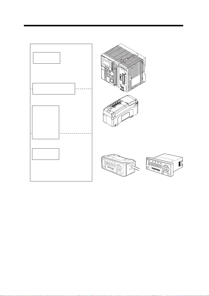
Relevant Manuals
PLC CPU unit
DeviceNet master unit
DL-DN1 (This unit)
Manuals relevant
to CPU unit
Manuals relevant to
DeviceNet master unit
This manual
Manuals of sensor
amplifier main unit
Example:
・
GT2-70 series user's manual
・
IG series user's manual
・
FD-MH series instruction manual
KV-DN20
MS
NS
O
N
TERM.
Sensor amplifier
Example: KV-5000 user's manual
Example: KV-DN20 user's manual
The manuals relevant to this document are as follows:
4
- DeviceNet Compatible Network Unit DL-DN1 User's Manual -
Page 7
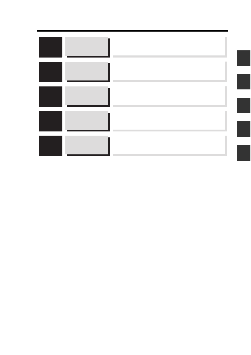
Manual Organization
1
2
3
4
5
Before Using
Connection and
Configuration
Communicating
with the IB
Series
Specifications
Appendix
This chapter provides an overview of the DL-DN1
and describes its part names and functions.
1
This chapter explains the procedures for
connecting sensor amplifiers to the DL-DN1
and how to configure the data link.
2
This chapter describes the configuration of the
memory linked to the DeviceNet master station and
provides communication time charts.
3
This chapter describes the specifications
and dimensions of the DL-DN1.
4
Provides the parameter list, as well as
troubleshooting instructions.
5
- DeviceNet Compatible Network Unit DL-DN1 User's Manual -
5
Page 8

Table of Contents
Safety Precautions ........................................................................................ 1
General Precautions ......................................................................... 1
Precautions for Use ........................................................................... 1
Notes on Regulations and Standards ............................................... 2
Relevant Manuals .......................................................................................... 4
Manual Organization ..................................................................................... 5
Table of Contents .......................................................................................... 6
Terms Used in This Document ..................................................................... 8
Chapter 1 Before Using
1-1 DL-DN1 Overview .............................................................................. 1-2
Overview ........................................................................................ 1-2
Types and Number of Connectable Sensor Amplifiers .................. 1-2
1-2 Checking the Package Contents ..................................................... 1-3
Package Contents .......................................................................... 1-3
1-3 Names and Functions of Each Part ................................................. 1-4
Chapter 2 Connection and Configuration
2-1 Installation and Connection to Sensor Amplifiers ......................... 2-2
ID Number Assignments to Sensor Amplifiers ............................... 2-2
Installation and Connection to Sensor Amplifiers ........................... 2-3
2-2 Wiring ................................................................................................. 2-7
Connecting to the DeviceNet ......................................................... 2-7
2-3 Configuring the Data Link .............................................................. 2-10
Configuring the Master Unit ......................................................... 2-10
Configuring the DL-DN1 ............................................................... 2-11
Chapter 3 Communicating with the IB Series
3-1 Overview of DeviceNet Communication ......................................... 3-2
Data Communicated Using DeviceNet ........................................... 3-2
Overview of Communication Methods ........................................... 3-3
3-2 I/O Communication ........................................................................... 3-4
Selecting the DL-DN1 Operating Mode .......................................... 3-4
Configuring the Operating Mode Setting Switch ............................ 3-5
Occupied Memory .......................................................................... 3-5
Device Maps .................................................................................. 3-7
Communication Methods .............................................................3-15
3-3 Explicit Messaging .......................................................................... 3-20
6
- DeviceNet Compatible Network Unit DL-DN1 User's Manual -
Page 9

Table of Contents
Basic Formats of Explicit Messaging ........................................... 3-20
Issuing a Motion Command to a Sensor Amplifier ....................... 3-22
Reading/Writing Settings or Status of a Sensor Amplifier ............3-23
Locking Sensor Amplifiers ............................................................ 3-25
Command Parameter List ............................................................ 3-26
Chapter 4 Specifications
4-1 Specifications .................................................................................... 4-2
4-2 Data Processing Times .................................................................... 4-3
4-3 Dimensions ........................................................................................ 4-5
Chapter 5 Appendix
5-1 Connecting with Sensor Amplifiers ................................................ 5-2
Connectable Sensor Amplifiers ...................................................... 5-2
Mixed Connection of Sensor Amplifiers .........................................5-3
5-2 DeviceNet Device Profile .................................................................. 5-4
Device Profile ................................................................................. 5-4
5-3 Troubleshooting ................................................................................ 5-5
5-4 Index ................................................................................................... 5-8
- DeviceNet Compatible Network Unit DL-DN1 User's Manual -
7
Page 10

Terms Used in This Document
This document uses the following terms:
Te r m Description
Sensor A sensor amplifier.
Master unit A DeviceNet master unit.
Slave unit A DeviceNet slave unit.
Main unit A sensor amplifier that has a power line and can operate
alone.
Expansion unit A sensor amplifier that does not have a power line and
must be connected to a main unit.
D-bus The name of KEYENCE's wiring-saving system for sensor
amplifiers.
For example, the high-precision contact type digital sensors of the GT2-70 series support this system.
PGM A mode in which DeviceNet node addresses can be set by
software. Explicit messaging is used for setting the
addresses.
8
- DeviceNet Compatible Network Unit DL-DN1 User's Manual -
Page 11

Before Using
This chapter provides an overview of the DL-DN1 and describes its
part names and functions.
1-1 DL-DN1 Overview .............................................. 1-2
1-2 Checking the Package Contents ........................ 1-3
1-3 Names and Functions of Each Part.................... 1-4
1
- DeviceNet Compatible Network Unit DL-DN1 User's Manual -
1-1
Page 12

1-1
D-bus compatible sensor amplifier
PLC or other host device
(DeviceNet master unit)
DL-DN1 (This unit)
DeviceNet slave unit
KV-DN20
M
S
NS
ON
TERM.
DL-DN1 Overview
1
Overview
Before Using
The DL-DN1 operates as a slave unit of DeviceNet communication. Using DeviceNet
communications, the sensor amplifiers and other units connected to the DL-DN1 can
transmit their ON/OFF control signals and current values as communication data to a
PLC or other equipment.
The DL-DN1 supports DeviceNet I/O communication (polling) and explicit messaging.
I/O polling enables data communication without the need of a ladder program. Explicit
messaging allows for reading/writing sensor amplifier parameters and issuing motion
commands to the sensor amplifiers.
System configuration example
Types and Number of Connectable Sensor Amplifiers
The DL-DN1 can connect a maximum of 15 sensor amplifiers (main units and expansion units) which support D-bus. "D-bus" is the name of KEYENCE's wiring-saving
system for sensor amplifiers.
Different types of sensor amplifiers with D-bus support can be connected to a single
DL-DN1 unit.
How many and what types of sensor amplifiers can be connected depends on the
sensor amplifiers or units to be connected. For details, refer to the user's manual of
your sensor amplifiers and "Connecting with Sensor Amplifiers" (page 5-2) in this
manual.
1-2
- DeviceNet Compatible Network Unit DL-DN1 User's Manual -
Page 13
1-2
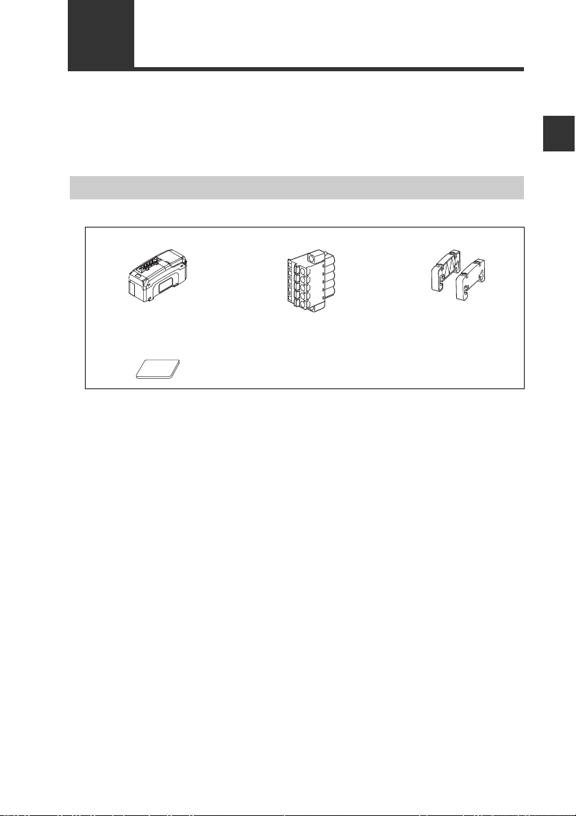
Before using the DL-DN1, make sure that the following equipment and accessories
are included in the package.
We have thoroughly inspected the package contents before shipment. However, in the
event of defective or broken items, contact your nearest KEYENCE office.
Package Contents
DL-DN1 main unit x 1 DeviceNet connector x 1 End unit x 2
Checking the Package Contents
1
Before Using
Expansion connector
sticker x 1
Instruction Manual x 1
- DeviceNet Compatible Network Unit DL-DN1 User's Manual -
1-3
Page 14
1
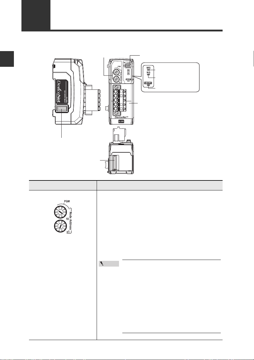
(6) Sensor amplifier connector
(for DIN rail mounting type)
(8) DeviceNet connector
(2) Operating mode setting switch
(1) Address setting switch
(7) Sensor amplifier connector
(for panel mounting type
and large display type)
(4) Network status indicator (green/red)
(5) Sensor communication indicator (green/red)
(3) Module status indicator (green/red)
1-3
This section describes the part names and functions of the DL-DN1.
Before Using
(1)Address setting switch Sets the DeviceNet node address of the DL-DN1.
Names and Functions of Each Part
Item Description
x10 : Ten's digit
x1 : One's digit
1-4
Setting range: 00 to 63
Default value: 63
When setting the node address of the DL-DN1 from
the DeviceNet master unit, set it in the range of 64 to
99. The DL-DN1 is switched to PGM mode.
Point
When the DL-DN1 is set in the PGM mode
- DeviceNet Compatible Network Unit DL-DN1 User's Manual -
and the power is turned on, the address
of the DL-DN1 is the same as used when
the DL-DN1was started last time.
When the DL-DN1 in the factory default
setting is set to the PGM mode, the node
address of the DL-DN1 is 63. Do not start
multiple DL-DN1 units in factory default
setting in the PGM mode, as that will
result in a network error because of the
duplicate node addresses.
Page 15
Item Description
Switch setting Operating mode
Occupied memory
IN area OUT area
3-output mode 8 byte 0 byte
5-output mode 12 byte 0 byte
"3-output + current value"
mode
14 to 70 byte 0 byte
"5-output + current value"
mode
18 to 74 byte 0 byte
Switch setting Operating mode
Occupied memory
IN area OUT area
No extended mode
--
External input mode
14 to 84 byte 6 to 10 byte
"External input +
BANK change"
mode
18 to 88 byte 10 to 14 byte
"External input +
setting value change" mode
22 to 96 byte 24 to 40 byte
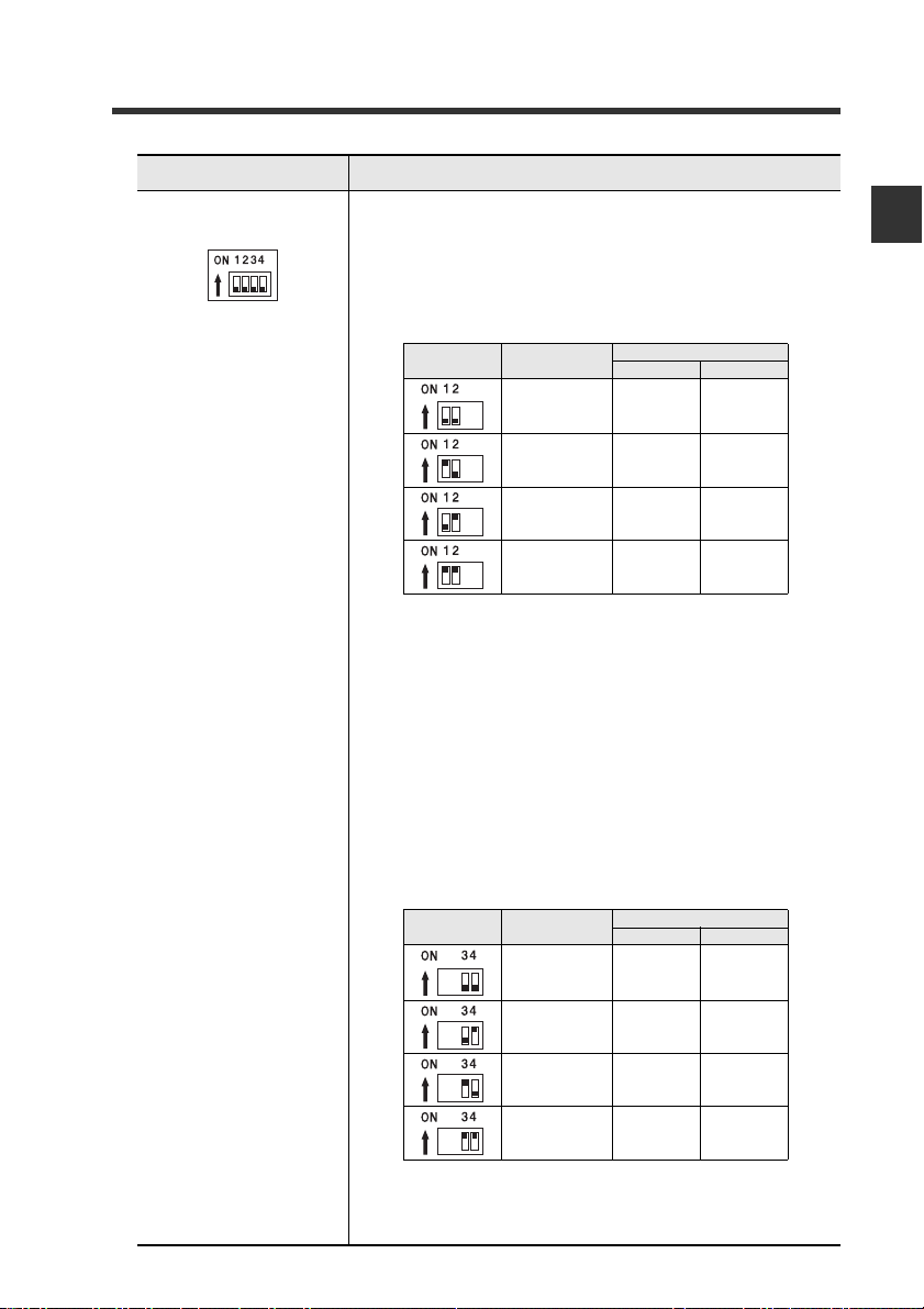
(2)Operating mode set-
ting switch
1-3 Names and Functions of Each Part
Sets the operating mode of the DL-DN1 in the DeviceNet.
The data that can be handled in remote I/O communication varies with each operating mode.
Basic mode
Use switch bits 1 and 2 to configure the basic mode.
Default value: 3-output mode
• The contents of output and current value vary depending on the sensor amplifiers to be connected.
Examples: 3-level judgment output for 3-output mode;
5-level judgment output for 5-output mode. Current
value: comparator value.
• The size of occupied memory depends on the number
of amplifiers to be connected.
1
Before Using
Extended mode
Switch bits 3 and 4 can be set to add one of the following
extended functions to the basic mode.
Default value: No extended mode
- DeviceNet Compatible Network Unit DL-DN1 User's Manual -
The size of occupied memory depends on the number of
amplifiers to be connected.
1-5
Page 16

1
Black
Blue
White
Red
1-3 Names and Functions of Each Part
Item Description
(3)Module status
indicator
Before Using
(4)Network status
indicator
(5)Sensor communica-
tion indicator
(6)Sensor amplifier
connector (for DIN
rail mounting)
(7)Sensor amplifier
connector (for panel
mounting/large display)
(8)DeviceNet connector Attach the DeviceNet cable to this connector.
When normal: Lit in green
For details, see "Troubleshooting" (page 5-5).
Indicates the status of communication between the DLDN1 and sensor amplifiers.
When normal: Lit in green
For details, see "Troubleshooting" (page 5-5).
Attach the sensor amplifier to this connector.
Attach the sensor amplifier to this connector.
When shipped from the factory, a protective sticker is
installed.
The optional expansion cable (OP-35361) is used for this
connection.
Wire color Signal name Function
Black V -
Blue CAN_L Communication signal (Low)
Bare wire SHIELD
White CAN_H Communication signal (High)
Red V +
Connects 0 VDC of the communication power supply.
Connects the shield of the DeviceNet cable.
Connects 24 VDC of the communication power supply.
1-6
- DeviceNet Compatible Network Unit DL-DN1 User's Manual -
Page 17

Connection and Configuration
This chapter explains the procedures for connecting sensor
amplifiers to the DL-DN1 and how to configure the data link.
2-1 Installation and Connection to Sensor Amplifiers........ 2-2
2-2 Wiring ................................................................. 2-7
2-3 Configuring the Data Link................................. 2-10
2
- DeviceNet Compatible Network Unit DL-DN1 User's Manual -
2-1
Page 18

2
Connection and Configuration
2-1
This section provides the procedures for installing the DL-DN1 and connecting to
sensor amplifiers.
The DL-DN1 can be connected with the expansion units of sensor amplifiers which
support D-bus. ("D-bus" is the name of KEYENCE's wiring-saving system for sensor
amplifiers.) How many sensor amplifiers can be connected depends on the sensor
amplifiers or units to be connected. For specific numbers of connections, refer to the
manual of each sensor amplifier.
Installation and Connection to Sensor Amplifiers
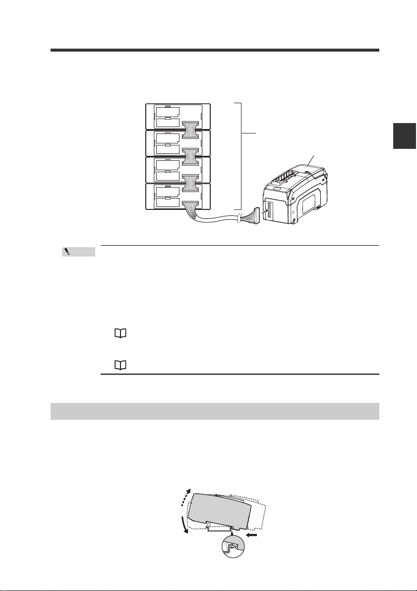
ID Number Assignments to Sensor Amplifiers
When connecting the DL-DN1 to a sensor amplifier which can be configured with
expansion units, the main unit will be assigned ID number 01, with the expansion units
assigned ID numbers of 02 to 04.
Point
• The ID number assignments to sensor amplifiers cannot be
changed by the user.
• In this manual, ID number 01 to ID number 04 are denoted as ID 01
to ID 04, respectively.
For DIN rail mounting type
2-2
ID number
- DeviceNet Compatible Network Unit DL-DN1 User's Manual -
01
02 03 04
Main
unit
Expansion
Expansion
unit
Sensor amplifier DL-DN1
unit
Expansion
unit
Page 19
For panel mounting type
Point
(1)
(2)
(3)
2-1 Installation and Connection to Sensor Amplifiers
ID number
• Since ID numbers are assigned automatically, changing the number of sensor amplifiers or their connection sequence may require
modification of the control program. In addition, some units are
restricted in their connection sequence (e.g., a unit that must be
the last connection). These considerations should be taken when
configuring the control program.
• Changing the number of connected sensors may change the memory area reserved in the DL-DN1.
• An error results if more sensor amplifiers are connected than the
maximum number of connectable amplifiers.
Sensor amplifier
01
02
03
04
"I/O Communication" (page 3-4)
"Error information list" (page 3-8)
Main unit
Expansion unit
Expansion unit
Expansion unit
Sensor amplifier
DL-DN1
2
Connection and Configuration
Installation and Connection to Sensor Amplifiers
Mounting on a DIN rail
Align the claw on the bottom of the amplifier with the DIN rail. While push-
1
ing the amplifier in the direction of arrow (1), press down in the direction
of arrow (2).
- DeviceNet Compatible Network Unit DL-DN1 User's Manual -
2-3
Page 20
2
NOTICE
Point
Sensor amplifier
Expansion protective cover
2-1 Installation and Connection to Sensor Amplifiers
To remove the DL-DN1, raise the main unit in the direction of arrow (3)
2
while pushing it the direction of arrow (1).
Procedures for connecting to sensor amplifiers
The DeviceNet compatible communication unit DL-DN1 must be connected to sensor
amplifiers before it can function.
The connecting procedure varies with the mounting type of the sensor amplifiers to be
Connection and Configuration
connected.
Make sure that the power to the sensor amplifier is off before starting to
connect the DeviceNet compatible communication unit, DL-DN1. Performing the procedure with the power on may damage the DL-DN1.
For the instructions on connecting additional sensor amplifiers, refer
to the instruction manual of the sensors amplifiers.
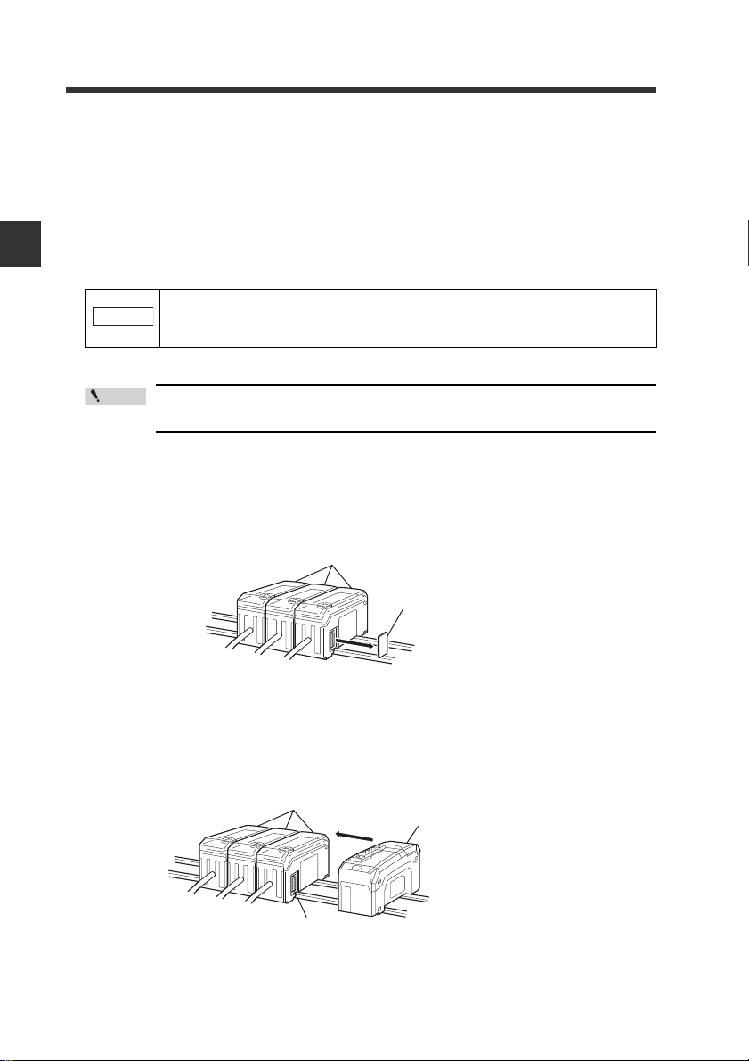
● Connecting to sensor amplifiers (DIN rail mounting type)
Remove the expansion protective cover from the sensor amplifier to be
1
connected.
2
2-4
Install the DeviceNet compatible communication unit, DL-DN1, on the DIN
rail and connect to the sensor amplifier.
Ensure a tight connection, leaving no space between the DeviceNet compatible
communication unit, DL-DN1, and the sensor amplifier.
Sensor amplifier
Connector
- DeviceNet Compatible Network Unit DL-DN1 User's Manual -
DeviceNet compatible communication
unit DL-DN1
Page 21
2-1 Installation and Connection to Sensor Amplifiers
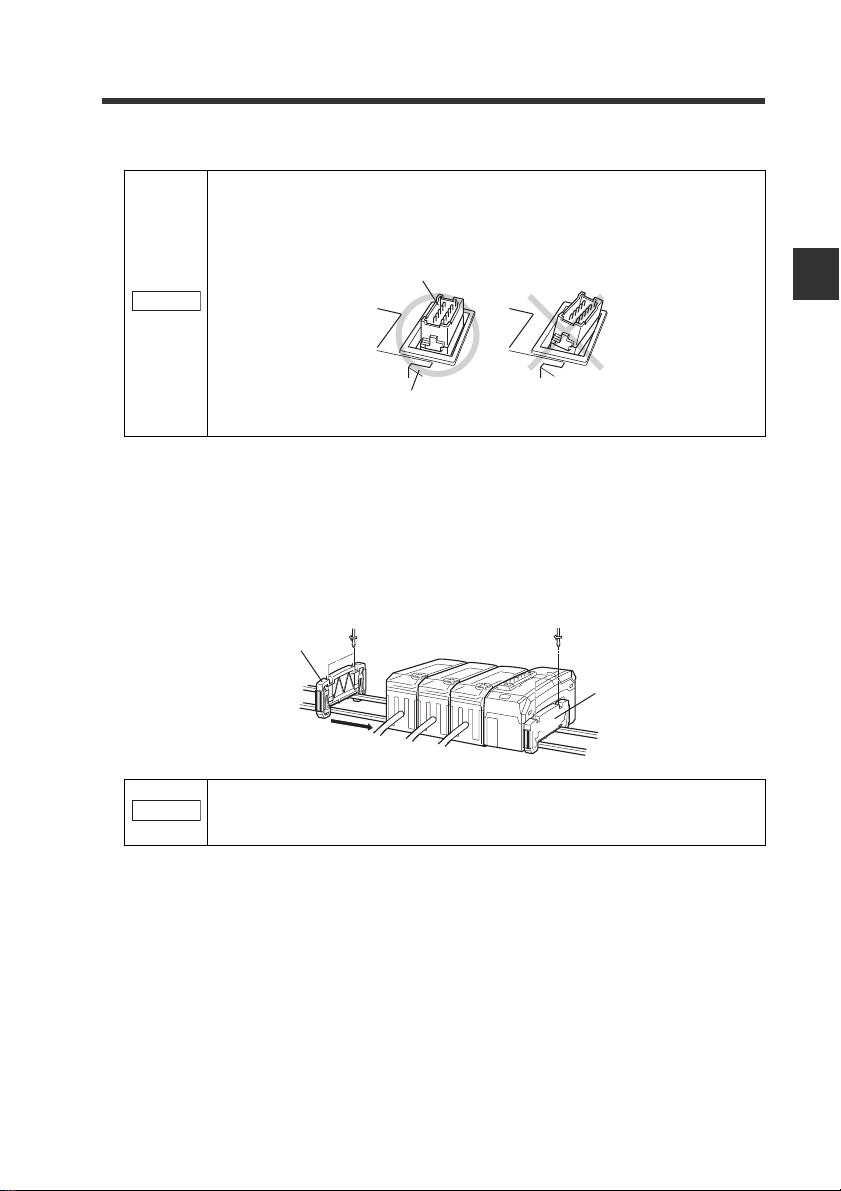
NOTICE
End unit
End unit
NOTICE
Make sure that the sensor amplifier connector (for DIN rail mounting
type) is not askew on the side face of the DeviceNet compatible communication unit, DL-DN1, as shown below. If the connector is askew, the DLDN1 may become damaged when connected to the sensor amplifier.
Sensor amplifier connector
DeviceNet compatible
communication unit DL-DN1
Mount the supplied end units (OP-26751: a set of two pieces) on the outer
3
side faces of the amplifier and the DeviceNet compatible communication
unit, DL-DN1. Then, fix the end units with the screws on the top of each
end unit (2 points x 2 units).
Mount the end units in the same way as the DeviceNet compatible communication unit, DL-DN1.
2
Connection and Configuration
Press the DeviceNet compatible communication unit DL-DN1 into full
engagement with the sensor amplifier. If the DL-DN1 is not correctly connected, it may be damaged when the power is turned on.
- DeviceNet Compatible Network Unit DL-DN1 User's Manual -
2-5
Page 22

2
Peel off the protective sticker.
Expansion cable (300 mm long)
NOTICE
Sensor amplifier connector
(for DIN rail mounting type)
Expansion connector sticker
2-1 Installation and Connection to Sensor Amplifiers
● Connecting to sensor amplifiers (panel mounting type)
Connect the optional expansion cable (OP-35361) between the sensor
1
amplifier and the DeviceNet compatible communication unit, DL-DN1.
Connection and Configuration
• Turn off the power and connect the expansion cable securely. If
the cable is not correctly connected, the DL-DN1 may be
damaged when the power is turned on.
• Do not attach or detach the cable with the power on, as this may
damage the DL-DN1.
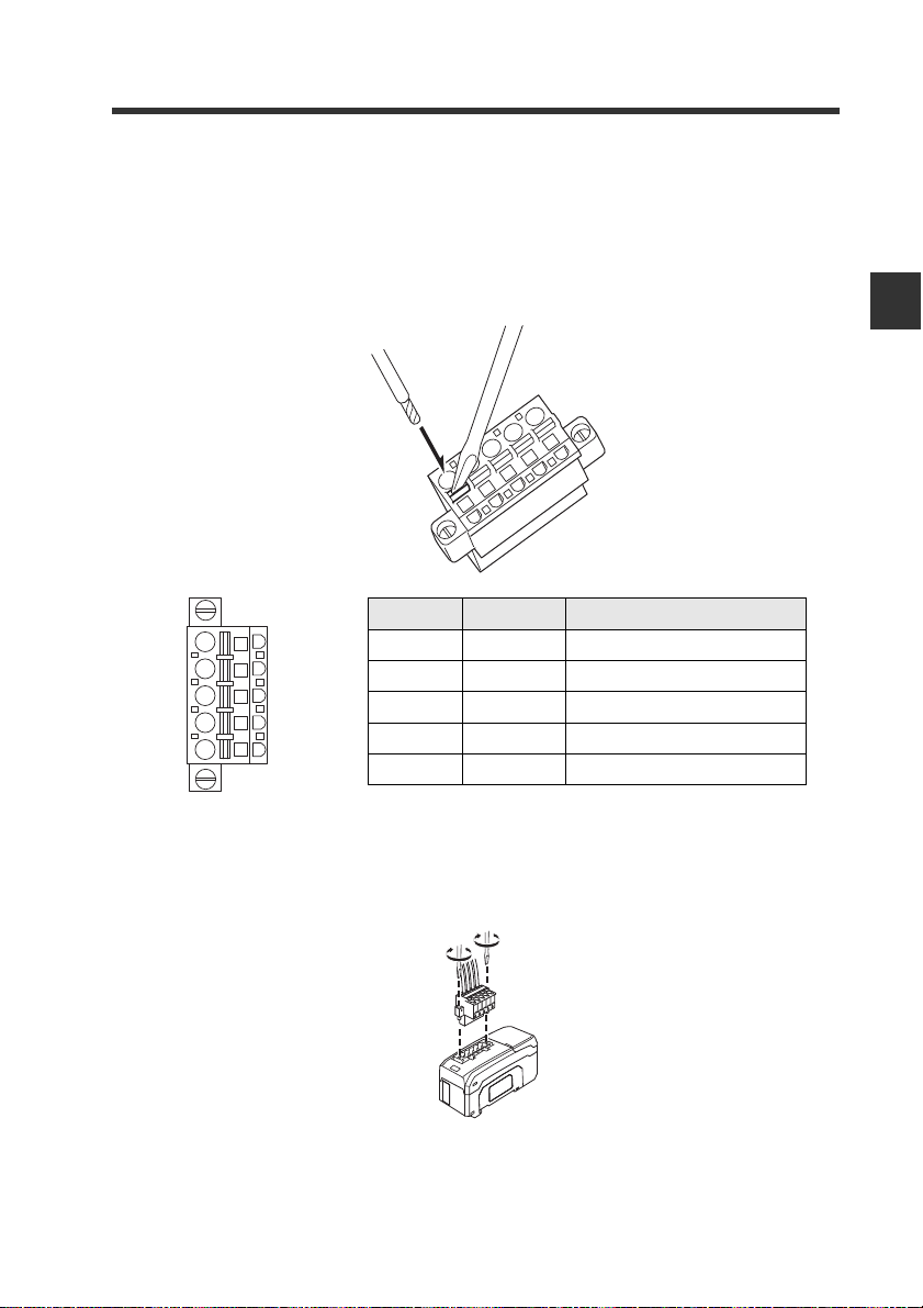
Remove the sensor amplifier connector (for DIN rail mounting type) from
2
the DeviceNet compatible communication unit, DL-DN1, using pliers. In its
place, attach the expansion connector sticker supplied with the DL-DN1.
2-6
- DeviceNet Compatible Network Unit DL-DN1 User's Manual -
Page 23
2-2
Point
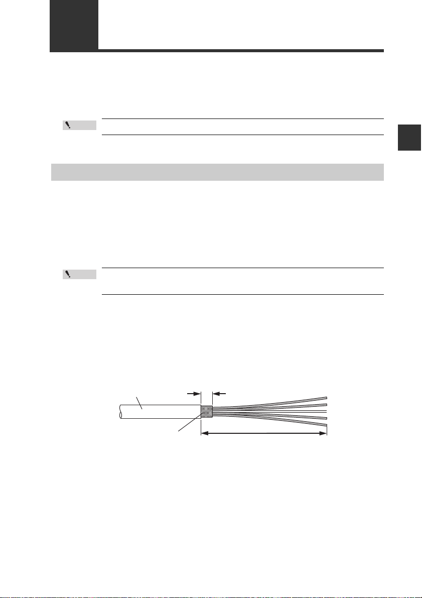
6 mm or shorter
Approx. 70 mm
Shield braid
Sheath
This section describes how to wire the DL-DN1.
Refer also to the DeviceNet Installation Manual published by ODVA.
Wiring
Turn off the power before wiring.
Connecting to the DeviceNet
Use the following procedure to connect the DL-DN1 to the DeviceNet.
Recommended cables
For connection between the DL-DN1 and the DeviceNet, use a dedicated DeviceNet
cable conforming to the DeviceNet specifications or a dedicated flat cable.
Point
Do not use non-dedicated cables, as this may inhibit proper communication.
Trimming the cable
2
Connection and Configuration
Strip the cable sheath.
1
Strip approximately 70 mm of cable sheath.
Make sure that the bare part of the shield braid is 6 mm or shorter.
- DeviceNet Compatible Network Unit DL-DN1 User's Manual -
2-7
Page 24
2
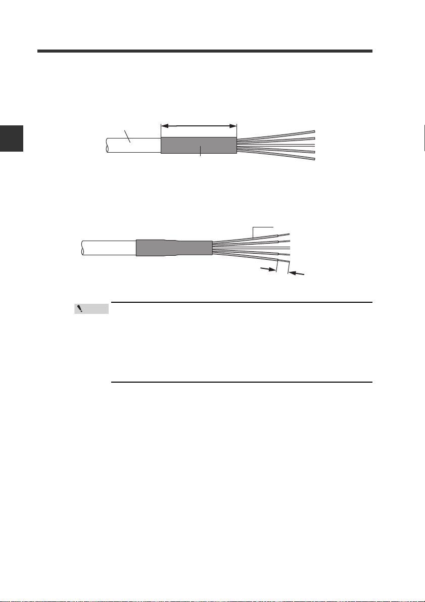
Approx. 10mm
Sheathed conductor
Point
2-2 Wiring
2
Install a shrinkable tube.
Cover the exposed sheathed conductors and the sheath using a shrinkable
tube approximately 40 mm long.
Sheath
Approx. 40mm
Connection and Configuration
Shrinkable tube
Strip the sheathed conductors.
3
Strip approximately 10 mm of sheath from the end of each conductor.
• If you are using solderless terminals, perform cable wiring/
trimming appropriately to suit the specifications of the particular terminals.
Recommended solderless terminals: Phoenix Contact's A/AI
Series
• Do not perform soldering (pre-soldering) on the trimmed end
of the cable.
2-8
- DeviceNet Compatible Network Unit DL-DN1 User's Manual -
Page 25
2-2 Wiring
Connecting the cable
Use the following procedures to wire to the DeviceNet connector supplied with the DLDN1.
Connect the trimmed cable to the DeviceNet connector.
1
Insert the cable completely.
Wire color Signal name Function
Black
Blue
White
Red
Black V -
Blue CAN_L Communication signal (Low)
Bare wire SHIELD
White CAN_H Communication signal (High)
Red V +
Connects 0 VDC of the communication power supply.
Connects the shield of the DeviceNet cable.
Connects 24 VDC of the communication power supply.
2
Connection and Configuration
Attach the DeviceNet connector to the DL-DN1.
2
Plug the connector into the DL-DN1 and secure it down with the screws on each
end. (Tightening torque: 0.2 to 0.3 N•m)
- DeviceNet Compatible Network Unit DL-DN1 User's Manual -
2-9
Page 26

2
Point
Reference
Reference
Connection and Configuration
2-3
Use the following procedure to connect the DL-DN1 to the DeviceNet system.
Configuring the Data Link
This manual covers only the functions and settings of a DeviceNet master
unit which are required for communication with the DL-DN1. For the functions
and settings related to the communication between the DeviceNet master unit
and CPU unit, refer to the manuals shipped with your master unit or CPU unit.
Configuring the Master Unit
The following configurations are required to connect the DL-DN1 to the DeviceNet
master unit.
Slave attribute settings
Configure the master unit with the communication form, I/O size, and other
information about the slave units. For this purpose, the EDS file for the DL-DN1 can
be imported into the configuration software of the master unit.
The EDS file can be downloaded from the KEYENCE web site:
http://www.keyence.com
Memory allocation settings
Configure the memory areas required for exchanging data through I/O
communication. Do this using the configuration software of the master unit.
Point
• The memory allocations must be reconfigured if the number of
connected sensors is changed, because the memory area
reserved in the DL-DN1 may change.
• Cautions for connecting the Keyence master unit KV-DN20
Assign the memory allocation start address either to odd-numbered addresses or to even-numbered addresses according to
operating modes of the DL-DN1 (refer to page 2-11). The current
value may not be read out correctly if the assignment is not proper.
Assign to odd-numbered addresses:
3-output + current value (no extended) mode
5-output + current value (no extended) mode
Assign to even-numbered addresses:
Operating modes other than the above
Where multiple slave units are connected, the memory allocation for each
slave unit is done automatically, based on the specified starting address.
The allocation information for each slave unit can be checked using DeviceNet configuration software.
2-10
- DeviceNet Compatible Network Unit DL-DN1 User's Manual -
Page 27

2-3 Configuring the Data Link
A
Configuring the DL-DN1
Use the following procedures to configure the data link of the DL-DN1.
Operating mode setting switch
ddress setting switch
Setting the node address
Using the address setting switch, set the DeviceNet node address to be assigned to
the DL-DN1.
• Default value: 63
• Setting range: 00 to 63
When setting the node address of the DL-DN1 from the DeviceNet master unit, set it
in the range of 64 to 99. The DL-DN1 enters PGM mode.
Point
When the DL-DN1 is set in the PGM mode and the power is turned on,
the address of the DL-DN1 is the same as used when the DL-DN1was
started previously.
When the DL-DN1, in the factory default setting, is set to PGM mode,
the node address of the DL-DN1 is 63. Do not start multiple DL-DN1
units in factory default setting in the PGM mode, as that will result in
a network error because of the duplicate node addresses.
2
Connection and Configuration
Selecting an operating mode
Select the desired operating mode of the DL-DN1 using the operating mode setting
switch.
The data that can be handled in I/O communication varies with each operating mode.
- DeviceNet Compatible Network Unit DL-DN1 User's Manual -
2-11
Page 28

2-3 Configuring the Data Link
Reference
Basic mode
Use switch bits 1 and 2 to configure the basic mode.
Switch setting Operating mode
3-output mode 8 byte 0 byte
Occupied memory
IN area OUT area
2
Connection and Configuration
5-output mode 12 byte 0 byte
"3-output + current value"
mode
"5-output + current value"
mode
14 to 70 byte 0 byte
18 to 74 byte 0 byte
Default value: 3-output mode
• The output content depends on the sensor amplifiers to be connected.
Examples: 3-level judgment output in 3-output mode; 5-level judgment output in 5output mode
• The size of the occupied memory depends on the number of amplifiers to be connected.
Extended mode
Switch bits 3 and 4 can be set to add one of the following extended functions to the
basic mode.
Switch setting Operating mode
No extended mode
External input mode
"External input +
BANK change"
mode
"External input +
setting value change" mode
Occupied memory
IN area OUT area
--
14 to 84 byte 6 to 10 byte
18 to 88 byte 10 to 14 byte
22 to 96 byte 24 to 40 byte
Default value: No extended mode
The size of the occupied memory depends on the number of amplifiers to be
connected and the setting of the basic mode.
Each switch should be set before turning on the power. If any setting
Point
is changed while the DL-DN1 is operating, the new setting will not be
applied until the power is turned on again. (The module status indicator flashes in red.)
The baud rate is set automatically to the value set on the DeviceNet master
unit.
2-12
- DeviceNet Compatible Network Unit DL-DN1 User's Manual -
Page 29

Communicating with the IB Series
This chapter describes the configuration of the memory linked to the
DeviceNet master unit and provides communication time charts.
3-1 Overview of DeviceNet Communication............. 3-2
3-2 I/O Communication............................................. 3-4
3-3 Explicit Messaging............................................ 3-20
3
- DeviceNet Compatible Network Unit DL-DN1 User's Manual -
3-1
Page 30

3
IN area
OUT area
Output
Judgment value
Error information
Request to change setting value
Changed setting value
External Input
DeviceNet
master unit
DL-DN1
Sensor amplifier
Output
Judgment value
・・・・・・
・・・・・・
・・・・・・
・・・・・・
・・・・・・
Error information
Setting value
Exteral input
Output
Judgment value
・・・・・・
・・・・・・
・・・・・・
・・・・・・
・・・・・・
Error information
Setting value
External Input
I/O
communication
I/O
communication
Explicit messaging
Output
Judgment value
・・・・・・
・・・・・・
・・・・・・
・・・・・・
・・・・・・
Error information
Setting value
Exteral input
IN area
OUT area
Read/write parameters
Communicating with the IB Series
3-1
Overview of DeviceNet Communication
The DL-DN1 operates as a slave unit of a DeviceNet system, with support for I/O
communication (polling) and explicit messaging. This section outlines the type of data
that the DL-DN1 can communicate using DeviceNet and how it is communicated.
Data Communicated Using DeviceNet
The master unit of the DeviceNet system and the DL-DN1 are linked as shown below.
3-2
- DeviceNet Compatible Network Unit DL-DN1 User's Manual -
Page 31

3-1 Overview of DeviceNet Communication
Overview of Communication Methods
The master unit of the DeviceNet system can use the following functions:
Function of
sensor amplifier
Read status
Read output 1to 5
Read current value
Execute external input 1to 5
Change BANK number
Rewrite setting value
Motion command
Read current value, setting,
and status
Read data with decimal
point information
Rewrite setting
Lock all
* When using these functions in explicit messaging, use the command parameters
for the functions assigned to external inputs 1 to 5. For details, see "Command
parameter list for IB series" (page 3-28)
I/O Communication
• The output signal, comparator value, and error status of sensor amplifiers can be
communicated without the need of a ladder program.
• By using the IN and OUT areas as handshake signals, the master unit can execute
external inputs to the sensor amplifier or change setting values.
"I/O Communication" (page 3-4)
I/O communication
*
Communication methods
p. 3-4
Ye s
No
Explicit messaging
p. 3-20
Ye s
3
Communicating with the IB Series
Explicit Messaging
The master unit can use explicit messaging commands to directly read/write
parameter values of sensor amplifiers. All functions that can be executed on sensor
amplifiers are available through explicit messaging.
"Explicit Messaging" (page 3-20)
- DeviceNet Compatible Network Unit DL-DN1 User's Manual -
3-3
Page 32

3
Communicating with the IB Series
3-2
I/O Communication
The device map varies depending on the operating mode of the DL-DN1. Select an
operating mode suited for the functions of the sensor amplifiers to be used, before
accessing each device.
The memory in the DeviceNet master unit is linked to the buffer memory in the DLDN1 as shown below.
DeviceNet master unit DL-DN1 Sensor amplifier
Output data
IN area
I/O communication
OUT area
I/O communication
Data here will be
reflected in the master unit.
Input data
Data here has been
output from the master unit.
Selecting the DL-DN1 Operating Mode
Select the DL-DN1 operating mode to suit the functions of the sensor amplifiers to be
used.
The DeviceNet device configuration and the data available for I/O communication
vary, depending on the selected operating mode of the DL-DN1 and the number of
connected sensor amplifiers. An appropriate operating mode should be determined
by considering the memory occupied and the data that can be communicated.
"Occupied Memory" (page 3-5)
Available function of sensor
amplifier
Read status
Read outputs
1 - 5
Read comparator value (PV value)
External
inputs
1 - 5
Change BANK number
Rewrite setting value No Yes No Yes No Yes No Yes 3-13 3-19
HIGH
LOW
GO
Check output
(Not used)
External input 1
External input 2
External input 3
External input 4
(Not used)
3-output
3-input
BANK
-
-
Ye s Ye s
No No
No Yes No Yes 3-10 3-17
No Yes No Yes
No No
Ye s N o
No
Operating mode of DL-DN1
3-output + current value
3-input
Setting
value
BANK
-
-
Ye s N o
No
5-output
Setting
value
-
-
Ye s Ye s
No Yes No Yes 3-11 3-16
No
5-input
BANK
Ye s N o
5-output + current value
Setting
value
-
No
5-input
-
Yes No 3-12 3-18
BANK
value
Setting
Device maps
method
3-7 3-15
3-9 3-15
Communication
3-4
- DeviceNet Compatible Network Unit DL-DN1 User's Manual -
Page 33

3-2 I/O Communication
Configuring the Operating Mode Setting Switch
Configure the operating mode setting switch to suit the operating mode to be used.
"Configuring the Operating Mode Setting Switch" (page 3-5)
DIP switch Operating mode
1 2 3 4 Output
OFF OFF OFF OFF
OFF ON OFF OFF Yes
OFF OFF OFF ON No
OFF ON OFF ON Yes
OFF OFF ON OFF No
OFF ON ON OFF Yes
OFF OFF ON ON No
OFFONONON Yes
ON OFF OFF OFF
ON ON OFF OFF Yes
ON OFF OFF ON N o
ON ON OFF ON Yes
ON OFF ON OFF No
ON ON ON OFF Yes
ON OFF ON ON No
ON ON ON ON Yes
3-output
5-output
Current
value
External
input
No
3-input
No
5-input
BANK
Setting value
change
No
No
Ye s
No Yes
No
No
Ye s
No Yes
rewrite
No
No
3
Communicating with the IB Series
Occupied Memory
The memory size occupied by the DL-DN1 varies with the selected operating mode
and the number of connected sensor amplifiers.
3-output mode
No extended mode Yes - - -
3-output
Area IN OUT IN OUT IN OUT IN OUT
Number of sensor amplifiers 1-4 8 0 14 6 18 10 22 24
- DeviceNet Compatible Network Unit DL-DN1 User's Manual -
3-input - Ye s Ye s Yes
BANK change - - Ye s -
Setting value rewrite - - - Ye s
(bytes)
3-5
Page 34

3
3-2 I/O Communication
"3-output + current value" mode
Communicating with the IB Series
5-output mode
"5-output + current value" mode
No extended mode Ye s - - -
3-output + monitor
Number of sensor
amplifiers
5-output
Number of sensor amplifiers 1-4 12 0 22 10 26 14 34 40
3-input - Ye s Ye s Ye s
BANK change - - Ye s -
Setting value rewrite - - - Ye s
Area IN OUT IN OUT IN OUT IN OUT
Area IN OUT IN OUT IN OUT IN OUT
114020
2 18242832
3 22283236
4 26323640
No extended mode Yes - - -
5-input - Ye s Ye s Yes
BANK change - - Ye s -
Setting value rewrite - - - Ye s
24
6
28
10
24
(bytes)
(bytes)
3-6
No extended mode Ye s - - -
5-output + current
value
Number of sensor
amplifiers
5-input - Ye s Ye s Ye s
BANK change - - Ye s -
Setting value rewrite - - - Ye s
Area IN OUT IN OUT IN OUT IN OUT
118028
2 22323644
3 26364048
4 30404452
32
10
- DeviceNet Compatible Network Unit DL-DN1 User's Manual -
40
14
40
(bytes)
Page 35

3-2 I/O Communication
Device Maps
The device map varies depending on the operating mode of the DL-DN1.
Access each device in a manner suitable for the selected operating mode.
"Status" (page 3-7)
"Output" (page 3-9)
"Comparator value (P.V. value)" (page 3-10)
"External input" (page 3-11)
"Changing a BANK" (page 3-12)
"Rewrite setting value" (page 3-13)
Status
IN area
Device
(DEC)
Name
n Status
n: The first device number assigned to the DL-DN1
Bit 7 Bit 6 Bit 5 Bit 4 Bit 3 Bit 2 Bit 1 Bit 0
Bit 15 Bit 14 Bit 13 Bit 12 Bit 11 Bit 10 Bit 9 Bit 8
Reserved Reser ved Reserved
Error
status
Warning
status
Sensor
ready
Error ID
number
(MSB)
Error code
(MSB)
Error ID
number
Error code Error code Error code
Error ID
number
Error ID
number
Error ID
number
(LSB)
Error code
(LSB)
3
Communicating with the IB Series
Status details
Error status
Sensor ready
Error ID number
Error code
Warning status
Name Description Reading range
An error occurred with the DL-DN1 or sensor amplifier, or the
DL-DN1 is not communicating properly with the sensor amplifier.
If an error exists, the error ID number and error code are stored.
The sensor amplifier has started and is ready. 0: Star ting
The error ID number is stored in the range of bit 0 (LSB) to bit 4
(MSB).
The error code is stored in the range of bit 8 (LSB) to bit 12
(MSB).
Indicates the check output status. 0: Check output OFF
0: No Error
1: Error
1: Ready
"Error information list"
(page 3-8)
1: Check output ON
(when in N.O.)
- DeviceNet Compatible Network Unit DL-DN1 User's Manual -
3-7
Page 36

3
3-2 I/O Communication
Error information list
Error
ID No.
00h
Communicating with the IB Series
nn㪿
(㪇㪈㪿㩷㫋㫆㩷
㪇㪝㪿)
1Dh
1Fh - No error - -
Error
code
(HEX)
01h Initialization error Error encountered during initial-
04h Mixed connection error A foreign sensor amplifier (i.e.,
06h Number-of-units error More sensor amplifiers are con-
01h Error 1 for sensor amplifier of
02h Error 2 for sensor amplifier of
03h Error 3 for sensor amplifier of
04h Error 4 for sensor amplifier of
05h Error 5 for sensor amplifier of
06h Error 6 for sensor amplifier of
07h Error 7 for sensor amplifier of
08h Error 8 for sensor amplifier of
09h Error 9 for sensor amplifier of
0Ah Error 10 for sensor amplifier of
0Bh Error 11 for sensor amplifier of
0Ch Error 12 for sensor amplifier of
02h/04
to 07h
03h Model error There is connected a sensor
Description Cause Corrective action
ization.
one that cannot be intermixed)
is connected.
nected than are permitted.
ID number nn
ID number nn
ID number nn
ID number nn
ID number nn
ID number nn
ID number nn
ID number nn
ID number nn
ID number nn
ID number nn
ID number nn
System error An error occurred in the internal
Overcurrent Error
EEPROM Error
Head error (light transmitter/
receiver)
Transmitter/Receiver reverse
connection error
Light emitter internal error
Light receiver error
Light transmitter error
Light transmitter laser error
Model mismatch error
Reference light intensity registration error
Adjust error
Amp-to-Amp communicaion
error
system.
amplifier of a model incompatible with the DL-DN1.
Check the number of connected sensor amplifiers and
the connection to the sensor
amplifiers, and then tur n off the
power and back on. If the error
cannot be recovered, contact
your nearest sales office.
Remove the foreign sensor
amplifier.
See "Mixed Connection of
Sensor Amplifiers" (page 5-3).
Observe the number of connectable sensor amplifiers.
Refer to the IB series user's
manual.
Check the connection to the
sensor, and then turn off the
power and back on. If the error
cannot be recovered, contact
your nearest sales office.
Connect a sensor amplifier of a
compatible model.
3-8
- DeviceNet Compatible Network Unit DL-DN1 User's Manual -
Page 37

Warning information list
3-2 I/O Communication
Warning information Warning code Description Cause Corrective action
nnh (01h to 0Fh) 01h
1Fh - No warning - -
ID No. "nn" sensor
amplifier warning 1
Check output status
Refer to the IB Series
User's Manual.
Output
Sensor amplifier ID numbers 01 to 04 are assigned to bits 0 to 3, respectively.
For details of communication methods, see "Reading an output from a sensor
amplifier" (page 3-15).
3-output mode
IN area
Device
(DEC)
n+1 HIGH
n+2 LOW
n+3 GO
Name
n: The first device number assigned to the DL-DN1
The device assignments are the same for all 3-output modes including extended
modes.
All 5-output modes
IN area
Device
(DEC)
n+1 HIGH
n+2 LOW
n+3 GO
n+4 Check output
n+5 Reserved
Name
n: The first device number assigned to the DL-DN1
The device assignments are the same for all 5-output modes including extended
modes.
Bit 7 Bit 6 ... Bit 1 Bit 0
Bit 15 Bit 14 ... Bit 9 Bit 8
ID08 ID07 ... ID02 ID01
Reserved ID15 ... ID10 ID09
ID08 ID07 ... ID02 ID01
Reserved ID15 ... ID10 ID09
ID08 ID07 ... ID02 ID01
Reserved ID15 ... ID10 ID09
Bit 7 Bit 6 ... Bit 1 Bit 0
Bit 15 Bit 14 ... Bit 9 Bit 8
ID08 ID07 ... ID02 ID01
Reserved ID15 ... ID10 ID09
ID08 ID07 ... ID02 ID01
Reserved ID15 ... ID10 ID09
ID08 ID07 ... ID02 ID01
Reserved ID15 ... ID10 ID09
ID08 ID07 ... ID02 ID01
Reserved ID15 ... ID10 ID09
ID08 ID07 ... ID02 ID01
Reserved ID15 ... ID10 ID09
3
Communicating with the IB Series
- DeviceNet Compatible Network Unit DL-DN1 User's Manual -
3-9
Page 38

3
3-2 I/O Communication
Comparator value (P.V. value)
The assigned positions for comparator values vary with different operating modes.
For details of communication methods, see "Reading comparator values (P.V.
values) from sensor amplifiers" (page 3-17).
"3-output + current value" mode
IN area
No extended
mode
Communicating with the IB Series
n+4 n+7 n+9 n+11
n+5-6 n+8-9 n+10-11 n+12-13 Comparator value ID01
n+7-8 n+10-11 n+12-13 n+14-15 Comparator value ID02
n+9-10 n+12-13 n+14-15 n+16-17 Comparator value ID03
n+11-12 n+14-15 n+16-17 n+18-19 Comparator value ID04
n: The first device number assigned to the DL-DN1
"5-output + current value" mode
IN area
No extended
mode
n+6 n+11 n+13 n+17
n+7-8 n+12-13 n+14-15 n+18-19 Comparator value ID01
n+9-10 n+14-15 n+16-17 n+20-21 Comparator value ID02
n+11-12 n+16-17 n+18-19 n+22-23 Comparator value ID03
n+13-14 n+18-19 n+20-21 n+24-25 Comparator value ID04
n: The first device number assigned to the DL-DN1
External
input
External
input
Device (DEC)
External input +
BANK change
Device (DEC)
External input +
BANK change
External input +
Setting value rewrite
External input
+ Setting value rewrite
Name
Comparator value
property
Name
Comparator value
property
Bit 7 Bit 6 ... Bit 1 Bit 0
Bit 15 Bit 14 ... Bit 9 Bit 8
ID08 ID07 ... ID02 ID01
Reserved
ID15 ... ID10 ID09
Outputs the current value of sensor
amplifier (ID**).
(4-byte signed integer)
Occupies a memory area proportional
to the number of connected sensor
amplifiers.
Bit 7 Bit 6 ... Bit 1 Bit 0
Bit 15 Bit 14 ... Bit 9 Bit 8
ID08 ID07 ... ID02 ID01
Reserved
ID15 ... ID10 ID09
Outputs the current value of sensor
amplifier (ID**).
(4-byte signed integer)
Occupies a memory area proportional to the number of connected
sensor amplifiers.
3-10
- DeviceNet Compatible Network Unit DL-DN1 User's Manual -
Page 39

3-2 I/O Communication
External input
Sensor amplifier ID numbers 01 to 15 are assigned to bits 0 to 14, respectively.
For details of communication methods, see "Entering an external input into a
sensor amplifier" (page 3-16).
3-output mode
OUT area
Device
(DEC)
m External input-1 request
m+1 Exter nal input-2 request
m+2 Exter nal input-3 request
Name
m: The first device number assigned to the DL-DN1
IN area
Device
(DEC)
n+4 External input-1 response
n+5 External input-2 response
n+6 External input-3 response
Name
n: The first device number assigned to the DL-DN1
The device assignments are the same for all 5-output modes including extended
modes.
Bit 7 Bit 6 ... Bit 1 Bit 0
Bit 15 Bit 14 ... Bit 9 Bit 8
ID08 ID07 ... ID02 ID01
Reserved ID15 ... ID10 ID09
ID08 ID07 ... ID02 ID01
Reserved ID15 ... ID10 ID09
ID08 ID07 ... ID02 ID01
Reserved ID15 ... ID10 ID09
Bit 7 Bit 6 ... Bit 1 Bit 0
Bit 15 Bit 14 ... Bit 9 Bit 8
ID08 ID07 ... ID02 ID01
Reserved ID15 ... ID10 ID09
ID08 ID07 ... ID02 ID01
Reserved ID15 ... ID10 ID09
ID08 ID07 ... ID02 ID01
Reserved ID15 ... ID10 ID09
3
Communicating with the IB Series
5-output mode
OUT area
Device
(DEC)
m External input-1 request
m+1 Exter nal input-2 request
m+2 Exter nal input-3 request
m+3 Exter nal input-4 request
m+4 Reserved
Name
Bit 7 Bit 6 ... Bit 1 Bit 0
Bit 15 Bit 14 ... Bit 9 Bit 8
ID08 ID07 ... ID02 ID01
Reserved ID15 ... ID10 ID09
ID08 ID07 ... ID02 ID01
Reserved ID15 ... ID10 ID09
ID08 ID07 ... ID02 ID01
Reserved ID15 ... ID10 ID09
ID08 ID07 ... ID02 ID01
Reserved ID15 ... ID10 ID09
ID08 ID07 ... ID02 ID01
Reserved ID15 ... ID10 ID09
m: The first device number assigned to the DL-DN1
- DeviceNet Compatible Network Unit DL-DN1 User's Manual -
3-11
Page 40

3
3-2 I/O Communication
IN area
Device
(DEC)
n+6 External input-1 response
n+7 External input-2 response
n+8 External input-3 response
n+9 External input-4 response
n+10 Reserved
Communicating with the IB Series
n: The first device number assigned to the DL-DN1
The device assignments are the same for all 5-output modes including extended
modes.
Changing a BANK
Sensor amplifier ID numbers 01 to 04 are assigned to bits 0 to 3, respectively.
For details of communication methods, see "Changing the BANK number of
sensor amplifiers" (page 3-18).
3-output mode
OUT area
Device
(DEC)
m+3 Request to change BANK
m+4 Select BANK number
m: The first device number assigned to the DL-DN1
Name
Name
Bit 7 Bit 6 ... Bit 1 Bit 0
Bit 15 Bit 14 ... Bit 9 Bit 8
ID08 ID07 ... ID02 ID01
Reserved ID15 ... ID10 ID09
ID08 ID07 ... ID02 ID01
Reserved ID15 ... ID10 ID09
ID08 ID07 ... ID02 ID01
Reserved ID15 ... ID10 ID09
ID08 ID07 ... ID02 ID01
Reserved ID15 ... ID10 ID09
ID08 ID07 ... ID02 ID01
Reserved ID15 ... ID10 ID09
Bit 7 Bit 6 ... Bit 1 Bit 0
Bit 15 Bit 14 ... Bit 9 Bit 8
ID08 ID07 ... ID02 ID01
Reserved ID15 ... ID10 ID09
Specifies a new BANK number
(2-byte unsigned integer; range: 0-3).
IN area
Device
(DEC)
n+7 BANK change complete
n+8 BANK change error
Name
Bit 7 Bit 6 ... Bit 1 Bit 0
Bit 15 Bit 14 ... Bit 9 Bit 8
ID08 ID07 ... ID02 ID01
Reserved ID15 ... ID10 ID09
ID08 ID07 ... ID02 ID01
Reserved ID15 ... ID10 ID09
n: The first device number assigned to the DL-DN1
The device assignments are the same for all 3-output modes including extended
modes.
3-12
- DeviceNet Compatible Network Unit DL-DN1 User's Manual -
Page 41

5-output mode
OUT area
Device
(DEC)
m+5 Request to change BANK
m+6 Select BANK number
Name
Bit 7 Bit 6 ... Bit 1 Bit 0
Bit 15 Bit 14 ... Bit 9 Bit 8
ID08 ID07 ... ID02 ID01
Reserved ID15 ... ID10 ID09
m: The first device number assigned to the DL-DN1
3-2 I/O Communication
Specifies a new BANK number
(2-byte unsigned integer; range: 0-3).
IN area
Device
(DEC)
n+11 BANK change complete
n+12 BANK change error
Name
Bit 7 Bit 6 ... Bit 1 Bit 0
Bit 15 Bit 14 ... Bit 9 Bit 8
ID08 ID07 ... ID02 ID01
Reserved ID15 ... ID10 ID09
ID08 ID07 ... ID02 ID01
Reserved ID15 ... ID10 ID09
n: The first device number assigned to the DL-DN1
The device assignments are the same for all 5-output modes including extended
modes.
Rewrite setting value
Sensor amplifier ID numbers 01 to 04 are assigned to bits 0 to 3, respectively.
For details of communication methods, see "Rewriting a setting value of a sensor
amplifier" (page 3-19).
3-output mode
OUT area
Device
(DEC)
n㪂㪊
n㪂㪋
n㪂㪍
n㪂㪎
n㪂㪐
n㪂㪈㪇
Name
Request to rewrite HIGH
setting value (BANK 0)
HIGH setting value (BANK 0)
Request to rewrite LOW
setting value (BANK 0)
LOW setting value (BANK 0)
Request to rewrite shift
target value (BANK 0)
Shift target value (BANK 0)
n: The first device number assigned to the DL-DN1
Bit 7 Bit 6 ... Bit 1 Bit 0
Bit 15 Bit 14 ... Bit 9 Bit 8
ID08 ID07 ... ID02 ID01
Reserved ID15 ... ID10 ID09
ID08 ID07 ... ID02 ID01
Reserved ID15 ... ID10 ID09
ID08 ID07 ... ID02 ID01
Reserved ID15 ... ID10 ID09
HIGH setting value to be rewritten
(4-byte signed integer)
LOW setting value to be rewritten
(4-byte signed integer)
Shift target value to be rewritten
(4-byte signed integer)
3
Communicating with the IB Series
- DeviceNet Compatible Network Unit DL-DN1 User's Manual -
3-13
Page 42

3
3-2 I/O Communication
IN area
Device
(DEC)
n㪂㪎
n㪂㪏
n㪂㪐
n㪂㪈㪇
n: The first device number assigned to the DL-DN1
Communicating with the IB Series
The device assignments are the same for all 3-output modes including extended
modes.
5-output mode
OUT area
Device
(DEC)
n㪂㪌
n㪂㪍
n㪂㪏
n㪂㪐
n㪂㪈㪈
n㪂㪈㪉
n㪂㪈㪋
n㪂㪈㪌
n㪂㪈㪎
n㪂㪈㪏
n: The first device number assigned to the DL-DN1
Name
Setting-value rewrite error
HIGH setting value (BANK 0)
rewrite complete
LOW setting value (BANK 0)
rewrite complete
Shift target value (BANK 0)
rewrite complete
Name
Request to rewrite HIGH
setting value (BANK 0)
HIGH setting value (BANK 0)
Request to rewrite LOW
setting value (BANK 0)
LOW setting value (BANK 0)
Request to rewrite shift
target value (BANK 0)
Shift target value (BANK 0)
Request to rewrite HIGH
setting value (BANK 1)
HIGH setting value (BANK 1)
Request to rewrite LOW
setting value (BANK 1)
LOW setting value (BANK 1)
Bit 7 Bit 6 ... Bit 1 Bit 0
Bit 15 Bit 14 ... Bit 9 Bit 8
ID08 ID07 ... ID02 ID01
Reserved ID15 ... ID10 ID09
ID08 ID07 ... ID02 ID01
Reserved ID15 ... ID10 ID09
ID08 ID07 ... ID02 ID01
Reserved ID15 ... ID10 ID09
ID08 ID07 ... ID02 ID01
Reserved ID15 ... ID10 ID09
Bit 7 Bit 6 ... Bit 1 Bit 0
Bit 15 Bit 14 ... Bit 9 Bit 8
ID08 ID07 ... ID02 ID01
Reserved ID15 ... ID10 ID09
ID08 ID07 ... ID02 ID01
Reserved ID15 ... ID10 ID09
ID08 ID07 ... ID02 ID01
Reserved ID15 ... ID10 ID09
ID08 ID07 ... ID02 ID01
Reserved ID15 ... ID10 ID09
ID08 ID07 ... ID02 ID01
Reserved ID15 ... ID10 ID09
HIGH setting value to be rewritten
(4-byte signed integer)
LOW setting value to be rewritten
(4-byte signed integer)
Shift target value to be rewritten
(4-byte signed integer)
HIGH setting value to be rewritten
(4-byte signed integer)
LOW setting value to be rewritten
(4-byte signed integer)
3-14
- DeviceNet Compatible Network Unit DL-DN1 User's Manual -
Page 43

3-2 I/O Communication
IN area
Device
(DEC)
Setting-value rewrite error
n㪂㪈㪈
HIGH setting value (BANK 0)
n㪂㪈㪉
LOW setting value (BANK 0)
n㪂㪈㪊
Shift target value (BANK 0)
n㪂㪈㪋
HIGH setting value (BANK 1)
n㪂㪈㪌
LOW setting value (BANK 1)
n㪂㪈㪍
Name
rewrite complete
rewrite complete
rewrite complete
rewrite complete
rewrite complete
Bit 7 Bit 6 ... Bit 1 Bit0
Bit 15 Bit 14 ... Bit 9 Bit 8
ID08 ID07 ... ID02 ID01
Reserved ID15 ... ID10 ID09
ID08 ID07 ... ID02 ID01
Reserved ID15 ... ID10 ID09
ID08 ID07 ... ID02 ID01
Reserved ID15 ... ID10 ID09
ID08 ID07 ... ID02 ID01
Reserved ID15 ... ID10 ID09
ID08 ID07 ... ID02 ID01
Reserved ID15 ... ID10 ID09
ID08 ID07 ... ID02 ID01
Reserved ID15 ... ID10 ID09
n: The first device number assigned to the DL-DN1
The device assignments are the same for all 5-output modes including extended
modes.
Communication Methods
The following describes how the DeviceNet master unit communicates with the DLDN1 (slave unit) using I/O communication (polling).
"Reading an output from a sensor amplifier" (page 3-15)
"Entering an external input into a sensor amplifier" (page 3-16)
"Reading comparator values (P.V. values) from sensor amplifiers" (page 3-17)
"Changing the BANK number of sensor amplifiers" (page 3-18)
"Rewriting a setting value of a sensor amplifier" (page 3-19)
For the communication methods using explicit messaging, see "Explicit
Messaging" (page 3-20).
3
Communicating with the IB Series
Reading an output from a sensor amplifier
Available outputs: HIGH, LOW, GO, and check output
Device assignments: "Output" (page 3-9)
PLC
Output of sensor amplifier
IN area [n+1]Bit0
Sensor amplifier
HIGH output of ID 01
This example reads the HIGH output from the sensor amplifier of ID01.
It assumes that the operating mode assigned to the device is 3-output mode.
(1)The output from the sensor amplifier is brought into the IN area by I/O communica-
tion.
- DeviceNet Compatible Network Unit DL-DN1 User's Manual -
Output
ON
OFF
1
0
(1)
3-15
Page 44

3
PLC
(1)
External Input request
OUTarea [m+1]Bit0
(2)
External Input response
IN
area
[n+5]Bit0
Sensor amplifier
External Input
External input 2 for ID 01
1
0
ON
OFF
1
0
Point
3-2 I/O Communication
Entering an external input into a sensor amplifier
Available external inputs: External inputs 1 - 4
Device assignments: "External input" (page 3-11)
Communicating with the IB Series
This example illustrates how to enter a TIMING input into the sensor amplifier of ID01.
It assumes that the operating mode assigned to the device is 3-output mode.
(1)The device value in the OUT area which is assigned an external input request is
linked via I/O communication, so that the external input of the sensor amplifier is
turned on or off.
(2)The input status of the sensor amplifier can be checked with the external input
response.
• An "amplifier unit external input ON" status is recognized when
either the "external input from communication" or the "amplifier
unit input signal line" is ON, and input operation is executed (OR
operation).
[Example] When a "laser beam stop input" setting is specified at
external input "n", the "laser beam stop" input is executed when either the "external input from communication" or the "amplifier unit input signal line" is ON.
• When bank switching is used, the amplifier unit's "BANK switching
method" must be specified as "external input switching".
3-16
- DeviceNet Compatible Network Unit DL-DN1 User's Manual -
Page 45

3-2 I/O Communication
PLC
(2)
Comparator value property
Each bit of IN [n+4]
Comparator value of ID 01
1234 4567 6789
IN area [n+5 to 6]
Comparator value of ID 02
2345 5678 7890
IN area [n+7 to 8]
Comparator value of ID 03
3456 8901
IN area [n+9 to 10]
Sensor amplifier
Comparator value of ID 01
1234 4567 6789
Comparator value of ID 02
2345 5678 7890
Comparator value of ID 03
3456 8901
(1)
Reading comparator values (P.V. values) from sensor amplifiers
Comparator values (P.V. values) are read by reading the IN areas which are assigned
the ID numbers of sensor amplifiers.
Device assignments: "Comparator value (P.V. value)" (page 3-10)
This example illustrates how to read the comparator values from the sensor amplifiers
of ID 01, 02, and 03.
It assumes that the operating mode assigned to the devices are "3-output mode +
current value, no extended."
(1)When the comparator value of a sensor amplifier is updated, the new comparator
value is entered into the IN area via I/O communication.
(2)The property of the comparator value is entered. If the comparator value of a sen-
sor amplifier is "over," "under," or "invalid," the bit corresponding to the ID number
of that sensor amplifier flips to 1.
3
Communicating with the IB Series
- DeviceNet Compatible Network Unit DL-DN1 User's Manual -
3-17
Page 46

3-2 I/O Communication
PLC
Select BANK number 1 (BANK 1) 3
OUT area [m+4]
Request to change BANK of ID 01
OUT area [m+3] BIT 0
Request to change BANK of ID 02
OUT area [m+3] BIT 1
(2)
Completed in changing BANK of ID 01
IN area [n+7] BIT 0
Completed in changing BANK of ID 02
IN area [n+7] BIT 1
(3)
BANK change error of ID 01
IN area [n+8] BIT 0
BANK change error of ID 02
IN area [n+8] BIT 1
Sensor amplifier
BANK number of ID 01 1 (BANK 1)
BANK number of ID 02 1 3
1
0
1
0
1
0
1
0
1
0
1
0
(1)
(4)
(BANK 1)
(BANK 3)
(BANK 3)
Point
Changing the BANK number of sensor amplifiers
Device assignments: "Changing a BANK" (page 3-12)
3
Communicating with the IB Series
This example changes the BANK number associated with ID01 and ID02.
It assumes that the operating mode assigned to the device is 3-output mode.
(1)Specify a new BANK number in "select BANK number" and execute "request to
change BANK" (0 -> 1). In this example, the BANK is changed for both ID01 and
ID02 simultaneously.
(2)The "BANK change complete" signal flips from 0 to 1 when the change to the spec-
ified BANK number is completed.
(3)The "BANK change error" signal flips from 0 to 1 if an error occurs during the
BANK change process. Check the value specified in the "select BANK number"
parameter.
(4)When the "request to change BANK" command is set to 0, the "BANK change
complete" and "BANK change error" parameters flip to 0.
The "BANK switching method" is set by button operation.
3-18
- DeviceNet Compatible Network Unit DL-DN1 User's Manual -
Page 47

3-2 I/O Communication
Point
PLC
(1)
Setting-value rewrite data
1234h
OUT area [m+4]
(2) (5)
Request to rewrite setting value
OUT area [m+3] BIT 0
(3)
Setting-value rewrite complete
IN area [n+8] BIT 0
(4)
Setting- value rewrite error
IN area [n+7] BIT 0
Sensor amplifier
Setting-value 1234h
1
0
1
0
1
0
Rewriting a setting value of a sensor amplifier
Available setting values: HIGH setting value (Bank0, Bank1), LOW setting value
(Bank0, Bank1), and zero shift setting value (Bank0)
Device assignments: "Rewrite setting value" (page 3-13)
The setting value to be rewritten is the values listed above. In case of
rewriting the setting value of a BANK number other than the values
listed above, see "Reading/Writing Settings or Status of a Sensor
Amplifier" (page 3-23).
Reference
When rewriting any setting or parameter other than listed above, use the
procedure described in "Reading/Writing Settings or Status of a Sensor
Amplifier" (page 3-23).
3
Communicating with the IB Series
This example changes the HIGH setting value of ID01.
It assumes that the operating mode assigned to the device is 3-output mode.
(1)Write the new setting value in the "setting-value rewrite data." For details of writ-
(2)Execute the "request to rewrite setting value" command (0 -> 1).
(3)After the setting value is rewritten, the "setting value rewrite complete" signal flips
(4)If an error occurs during "setting value rewriting" on the sensor amplifier, the "set-
(5)When the "request to rewrite setting value" command is set to 0, the "setting value
able ranges, see "Command parameter list for IB series" (page 3-28).
from 0 to 1.
ting value rewrite error" signal flips from 0 to 1. (The output is an OR sum of settings.) Check the value entered in the "setting-value rewrite data."
rewrite complete" and "setting value rewrite error" parameters flip to 0.
- DeviceNet Compatible Network Unit DL-DN1 User's Manual -
3-19
Page 48

3-3
DeviceNet master unit DL-DN1 Sensor amplifier
Receive
Receive
Send
Send
Response
Command
Node
address
Service
Code
Attribute
ID
When normal
When abnormal
Node
address
Node
address
Service
Code
Service
Code
ClassID
InstanceID
Service data
Response data
Response data
(Error code)
Received size
Received size
Reference
Explicit Messaging
The DeviceNet master unit can issue explicit messages to the DL-DN1 for the
following purposes:
"Issuing a Motion Command to a Sensor Amplifier" (page 3-22)
"Reading settings or status" (page 3-23)
"Reading data with decimal point" (page 3-24)
"Writing settings or status" (page 3-24)
"Locking Sensor Amplifiers" (page 3-25)
3
Communicating with the IB Series
Basic Formats of Explicit Messaging
Shown below is the basic format used when the DeviceNet master unit issues a
command to the DL-DN1 and when the DL-DN1 responds to the DeviceNet master
unit, respectively.
The number of bytes used in the class ID, instance ID, and attribute ID may
vary depending on the master unit. The format examples in this manual
assume 2 bytes for class ID, 2 bytes for instance ID, and 1 byte for attribute
ID. For details, refer to the instruction manual of the master device.
3-20
- DeviceNet Compatible Network Unit DL-DN1 User's Manual -
Page 49

Command format
Command Description
0Eh Read settings or status
10h Write settings or status
4Bh Motion command
4Ch Lock all
4Eh
Read information with decimal
point
Item Description
Node address
Service Code
3-3 Explicit Messaging
Specifies the node address, in hexadecimal, of the destination (DL-DN1) of the explicit
message.
Specifies the type of the command.
3
Communicating with the IB Series
Class ID Fixed to 0067h.
Instance ID
Attribute ID
Service data Specifies the data to be written.
Response format
Item Description
Number of received bytes Replies with the number of bytes of the received data.
Node address Replies with the node address of the responder (DL-DN1).
Service Code
The Instance ID and Attribute ID specify the ID number and parameter of the target sensor amplifier.
For specific values, see "Command Parameter List" (page 3-26).
[When normal]: Replies with the received Service Code by turning its most significant bit
to ON.
[When abnormal]: Fixed to 94h.
- DeviceNet Compatible Network Unit DL-DN1 User's Manual -
3-21
Page 50

3
Code
Command type
Description
Read
Write
Instruction
Lock
FF00h Successfully completed.
FF05h The instance ID is out of range.
FF08h "Instance ID: 0" is specified.
FF09h Data written is out of range.
FF0Ch
Failed to execute the motion command. Check
whether the sensor amplifier is a state capable
of executing the motion command.
FF0Eh
An attempt is made to write data in a writeprohibited attribute ID. The data is out of writable
range. The sensor amplifier is temporarily write
disabled.
FF10h
The system is in the startup process or is reflecting setting changes or the sensor amplifier is
temporarily read disabled.
FF13h Service data size is too small.
FF14h
Attribute ID is out of range (not between 64h and A3h).
An attempt is made to writ e instance ID0 data (common command parameter) to an attribute ID which
cannot receive this instance data.
FF16h
The sensor amplifier corresponding to the specified
instance ID and attribute ID is not connected.
FFFEh System error. Contact your nearest sales office.
Destination
node address
Service
Code
Attribute ID
**h 4Bh 0067h ****h **h
Specifi es a motion command parameter.
Class ID
Instance ID
3-3 Explicit Messaging
Response data Replies with the data that has been read out.
Communicating with the IB Series
Response data
(Error code)
Item Description
Replies with the content of the error.
Issuing a Motion Command to a Sensor Amplifier
Available motion commands: See "Motion command parameters" (page 3-28).
Commands can be used for purposes such as zero shift reset and reference light
registration (gain adjustment) .
Command format
3-22
- DeviceNet Compatible Network Unit DL-DN1 User's Manual -
Page 51

3-3 Explicit Messaging
Responder
node address
Se rv ice Code
0002h **h CBh 0000h
Response data Number of receiv ed b ytes
Responder
node address
Se rv ice Code
0002h **h 94h FF**h
Response data
(Error code)
Number of receiv ed b ytes
Destination
node address
Service
Code
Attribute ID
**h 0Eh 0067h ****h **h
Specifi es the parameter to be read.
Class ID
Instance ID
Responder
node address
Se rv ice Code
0002h **h 8Eh ****h
Response data
Number of receiv ed b ytes
Responder
node address
Se rv ice Code
0004h **h 8Eh ********h
Response data Number of receiv ed b ytes
Responder
node address
Service Code
0010h **h 8Eh ********************************h
Response data
Number of received bytes
Response format
• When normal
• When abnormal
Reading/Writing Settings or Status of a Sensor Amplifier
Reading settings or status
Available settings and status: See "Common command parameter list" (page 3-
26) and "Setting/status command parameters" (page 3-30).
Command format
3
Communicating with the IB Series
Service data need not be sent.
Response format
• When normal (for reading response data of WORD or UINT type)
• When normal (for reading response data of DINT type)
• When normal (for reading response data of STRING (16-byte) type)
- DeviceNet Compatible Network Unit DL-DN1 User's Manual -
3-23
Page 52

3
Responder
node address
Se rv ice Code
0002h **h 94h FF**h
Response data
(Error code)
Number of receiv ed b ytes
Destination
node address
Service
Code
Attribute ID
**h 4Eh 0067h ****h **h
Specifi es the parameter to be read.
Class ID
Instance ID
Responder
node
address
Service
Code
0006h **h CEh ********h ****h
Response data
Number of
received bytes
Decimal point
information
Responder
node address
Se rv ice Code
0002h **h 94h FF**h
Response data
(Error code)
Number of receiv ed b ytes
3-3 Explicit Messaging
• When abnormal
Reading data with decimal point
Command format
Communicating with the IB Series
Response format
• When normal
Decimal point information: Indicates the number of decimals.
For example, "0003h" means three decimals.
• When abnormal
Writing settings or status
Command format
• When writing data of WORD or UINT type
Destination
node address
**h 10h 0067h ****h **h ****h
3-24
Service
Code
Class ID Instance ID Service data
Specifi es the parameter to be written.
- DeviceNet Compatible Network Unit DL-DN1 User's Manual -
Attribute ID
Data to be written
Page 53

3-3 Explicit Messaging
Destination
node
address
Service
Code
Attribute ID
**h 10h 0067h ****h **h ********h
Class ID
Instance ID
Service data
Data to be written
Specifi es the parameter to
be written.
Responder
node address
Se rv ice Code
0002h **h 90h 0000h
Response data
Number of receiv ed b ytes
Responder
node address
Se rv ice Code
0002h **h 94h FF**h
Response data
(Error code)
Number of receiv ed b ytes
• When writing data of DINT type
Response format
• When normal (for writing response data of WORD, UINT, or DINT type)
• When abnormal
Locking Sensor Amplifiers
The following formats are used to activate the key lock on all sensor amplifiers
connected to the DL-DN1.
3
Communicating with the IB Series
Command format
Destination
node address
**h 4Ch 0067h 0000h (See below)
Service
Code
Class ID
Instance ID Service data
Service data
Service data Action Description
0000h Deactivate key lock Deactivates key lock.
0001h Activate key lock Activates key lock.
- DeviceNet Compatible Network Unit DL-DN1 User's Manual -
3-25
Page 54

3
Point
Responder
node address
Se rv ice Code
0002h **h CCh 0000h
Response data Number of receiv ed b ytes
Responder
node address
Se rv ice Code
0002h **h 94h FF**h
Response data
(Error code)
Number of receiv ed b ytes
3-3 Explicit Messaging
Error code 0Eh is returned if the DL-DN1 is connected with any sensor amplifier that does not support key lock or full key lock. (The settings of such non-supported sensor amplifiers remain unchanged.)
Response format
• When normal
Communicating with the IB Series
• When abnormal
Command Parameter List
The following tables list the command parameters used in explicit messaging to read/
write the settings and status of sensor amplifiers and to issue motion commands.
For details about how the master unit performs explicit messaging using command
parameters, see:
"Issuing a Motion Command to a Sensor Amplifier" (page 3-22)
"Reading/Writing Settings or Status of a Sensor Amplifier" (page 3-23)
Common command parameter list
The table below describes command parameters which are common to the DL-DN1.
InstID: Instance ID; AttrID: Attribute ID
Attribute R: Read; R/W: Read/Write
InstID
AttrID
(DEC)
(HEX)
64 Status
65 Error status
0
66 Warning status
67 System reserved
68
3-26
Name Description
Bit 0 - 12: Unused
Bit 13: Sensor ready
Bit 14: Warning status
Bit 15: Error status
The error status values of sensor
amplifiers (ID 01 to ID 04) are output
as they are assigned to bits 0 - 3.
The warning status values of sensor
amplifiers (ID 01 to ID 04) are output
as they are assigned to bits 0 - 3.
This property is output by assigning
Current value
property
- DeviceNet Compatible Network Unit DL-DN1 User's Manual -
sensor amplifiers (ID 01 to ID 04) bits
0 - 3.
The output occurs when the measured
value is nonnumeric: "over," "under,"
or "invalid."
Data
type
Default
value
Attribute
RWORD0*1
RWORD0
RWORD0
RWORD0
Parameter range
0: No error
1: Error
0: No error
1: Error
0: Normally measured value
1: "over," "under," or
"invalid (-----)"
Page 55

InstID
AttrID
(DEC)
(HEX)
69 to 6B System reserved
6C Error ID number
6D Error code R UINT 0
6E
6F Warning code R UINT 0
70 to 73 System reserved
74 HIGH
75 LOW
76 GO
77 Check output
78 (Not used)
79 to 8C System reserved
8D
0
8E
8F
90
~
93
9F to B0 System reserved
B1
B2 to B3 System reserved
B4
B5 to B9 System reserved
BA
Name Description
Error details.
If there are errors with multiple ID
numbers, the error information for the
Warn ing ID
number
Measured value
"invalid"
Measured value
"under"
Measured value
"over"
Current value ID
01
Current value ID
04
Number of
sensor amplifier
units connected
Explicit message
response method
Operating mode
switch status
smallest error code is output.
Warning details.
If there are errors with multiple ID
numbers, the warning information for
the smallest ID number is output.
The HIGH state is output by assigning
sensor amplifiers (ID 01 to ID 04) bits
0 - 3.
The LOW state is output by assigning
sensor amplifiers (ID 01 to ID 04) bits
0 - 3.
The GO state is output by assigning
sensor amplifiers (ID 01 to ID 04) bits
0 - 3.
The check output is output by assigning sensor amplifiers (ID 01 to ID 04)
bits 0 - 3.
If the measured values for sensor
amplifiers (ID 01 to ID 04) are "invalid"
(-----), they are output by assigning
them to bits 0 - 3.
If the measured values for sensor
amplifiers (ID 01 to ID 04) are "under,"
they are output by assigning them to
bits 0 - 3.
If the measured values for sensor
amplifiers (ID 01 to ID 04) are "over,"
they are output by assigning them to
bits 0 - 3.
Reads the current value of ID 01.
Same as the current value used in I/O
communication.
Reads the current value of ID 04.
Same as the current value used in I/O
communication.
Reads the number of connected sensor amplifiers.
If synchronous response is used,
response occurs synchronously with I/
O communication.
Set status of operating mode setting
switch: switch 1 (LSB) to switch 4
(MSB)
*1 "Status details" (page 3-7)
*2 "Error information list" (page 3-8)
3-3 Explicit Messaging
Data
type
DINT32
Default
value
0
Attribute
RUINT0
RUINT0
RWORD0
RWORD0
RWORD0
RWORD0
RWORD0
RWORD0
RWORD0
R
R UINT 0 1 to 4
R/W UINT 0
RUINT0
Parameter range
*2
*3
0: OFF
1: ON
0: OFF
1: ON
0: OFF
1: ON
0: OFF
1: ON
0: Normal value
1: Invalid
0: Normal value
1: Under
0: Normal value
1: Over
-2147483648 to
2147483647
0: Immediate
response
1: Synchronous
response
0 to 15
0: OFF, 1: ON
3
Communicating with the IB Series
- DeviceNet Compatible Network Unit DL-DN1 User's Manual -
3-27
Page 56

3
3-3 Explicit Messaging
*3 "Warning information list" (page 3-9)
Command parameter list for IB series
The following tables provide command parameters for the IB series. The two types of
parameters are: motion command parameters and setting/status command
parameters.
Motion command parameters
For the communication methods using motion command parameters, see "Issuing
a Motion Command to a Sensor Amplifier" (page 3-22).
Communicating with the IB Series
Before executing a motion command, check that the sensor amplifiers are ready to
execute motion commands. For instruction on making this check, see the IB series
user's manual. After an executing motion command, check that it has successfully
completed.
Attribute R: Read; C: Motion command
N: ID number of sensor amplifier
InstID
(DEC)
N
AttrID
(HEX)
65
Zero shift request
66
Zero shift reset request
67
Reset request
68
Error clear request
69
Initial reset request
System parameter set
6A
request
6B to
Reserved
6D
Reference light registration
6E
request
Name
Description
Executes zero shift. Turning off the power to the sensor amplifier
after executing zero shift restores the state that existed before
C
the zero shift function was used. If to retain the shifted state after
turning off the power, turn on the zero shift value memory function.
C Resets the zero shift value.
C Executes resetting.
Clears the reference light registration error [ErG] and adjustment
C
error [ErAdJ].
Initializes all settings, except for sensor amplifier calibration, reference light registration, and system parameters. Once an initial
reset request is executed, all parameters are stored into the non-
C
volatile memory (EEPROM) in approximately 12 seconds. After
finished, the setting/status command parameter "EEPROM writing result" flips to "successfully completed (1)".
Changes the system parameters (the settings of "judgment output/check output" polarity and analog output) to the settings contained in the setting/status command parameter "system
parameter."
When executing a system parameter set, ensure that the settings
C
are changed correctly to suit the connected equipment and wiring. A wrong change may damage the sensor amplifier or the
connected equipment.
The execution result can be checked with "system parameter
current state."
C Registers the reference light.
Attribute
3-28
- DeviceNet Compatible Network Unit DL-DN1 User's Manual -
Page 57

3-3 Explicit Messaging
InstID
(DEC)
N
AttrID
(HEX)
6F
70
71
72
73
74
75
76
77
78
79 to
7D
7E
7F
80 to
83
Name
Adjust request
Adjust reset request
Reserved
Tolerance tuning request
2-point tuning HIGH side 1st
request
2-point tuning HIGH side 2nd
request
2-point tuning LOW side 1st
request
2-point tuning LOW side 2nd
request
Measured correction 1st
*1
request
Measured correction 2nd
*1
request
Reserved
Logical correction 1st
*1
request
Logical correction 2nd
*1
request
Reserved
Description
Executes the adjustment function. Turning off the power to the
sensor amplifier after executing the adjustment function restores
C
the same state as before executing adjustment function. If to
retain the adjusted value after turning off the power, turn on the
save adjust state hold function.
C Initializes the adjustment value.
Executes tolerance tuning
C
The setting width of tolerance is set in the setting/status command parameter "tolerance tuning setting width."
C
C
Executes 2-point tuning.
For the operating procedure, refer to the IB Series User's Manual.
C
C
Executes measured correction.
C
The R. V. value to be displayed is set using the setting/status
command parameters "Measured/Logical correction target 1"
and "Measured/Logical correction target 2."
C
For the operating procedure, refer to the IB Series User's Manual.
Executes logical correction.
C
The R.V. value to be calibrated is set in the setting/status command parameters "Logical correction measured 1" and "Logical
correction measured 2."
The R. V. value to be displayed is set using the setting/status
command parameters "Measured/Logical correction target 1"
C
and "Measured/Logical correction target 2."
For the operating procedure, refer to the IB Series User's Manual.
Attribute
*1 Correction will not be possible if a setting change occurs between the target 1
and target 2 execution requests. When corrections are being performed, do not
change the settings during the processing.
Note also, that the "auto adjust" function is disabled between the target 1 and
target 2 execution requests. Be sure to follow the target 1 execution request
with a target 2 execution request.
3
Communicating with the IB Series
- DeviceNet Compatible Network Unit DL-DN1 User's Manual -
3-29
Page 58

3
3-3 Explicit Messaging
Setting/status command parameters
• For the communication methods using setting/status parameters,
see "Reading/Writing Settings or Status of a Sensor Amplifier" (page 3-23).
• To reduce the number of writes to the EEPROM, a write command is executed 2
seconds after it is received. If another command is received within 2 seconds, the
DL-DN1 waits for another 2 seconds before executing the two commands simultaneously. After the writing completes successfully, the "EEPROM writing result"
parameter becomes "successfully completed (1)". For example, if commands are
received continuously every second, they will not execute because the DL-DN1
remains "currently writing (0)". 2 seconds after the last command is received, the
commands received will be executed simultaneously.
• If data with a decimal point is used for a parameter range, ignore the decimal point
Communicating with the IB Series
and read or write the data as an integer. For example, to write a HIGH setting value
(BANK 0) of "+1.235" (size mode), write "+1235".
• Attribute R: Read; W: Write; R/W: Read/Write
• N: ID number of sensor amplifier; for example, if the ID number is 13, then N x 10 +
3 -> 133 (DEC).
• The data types are DINT unless explicitly specified.
InstID
(DEC)
Nx10+1
3-30
AttrID
(HEX)
64
Group-1 entry count
65
Error status
66
Warning status
67
Warning function operating state
68
Judgment output/Check output
69
Judgment value (P.V.)
6A
Internal measurement value (R.V.)
6B
Peak-hold value in hold mode
6C
Bottom-hold value in hold mode
6D
Reserved
6E
Analog output value
6F
Bank status
70
Timing status
Name
Description
*1 R
*2
*21
*3
*4
*4 R
*4
*5
*7
*4
*6
*7
*8 R
Default
Attribute
value
R29
R
R
R
R
R
R
R
R
- DeviceNet Compatible Network Unit DL-DN1 User's Manual -
Parameter range
0: Overcurrent error
1: EEPROM error
2: Head error
3: Transmitter/Receiver reverse connection
error
4: Transmitter internal error
5: Receiver error
6: Transmitter error
7: Transmitter laser error
8: Model mismatch error
9: Reference light registration error
10: Adjust error
11: Amp-to-Amp communication error
0: Check output OFF
1: Check output ON
0: Check output function disabled
1: Check output function enabled
0: HIGH judgment output 0: OFF, 1: ON
1: LOW judgment output 0: OFF, 1: ON
2: GO judgment output 0: OFF, 1: ON
3: Check output 0: OFF, 1: ON
-999.99 to +999.99
-999.99 to +999.99
-999.99 to +999.99
-999.99 to +999.99
Analog voltage output: -5.000 to +5.000
Analog current output: +04.00 to +20.00
0: Bank 0
1: Bank 1
2: Bank 2
3: Bank 3
0: During sampling
1: Not during sampling
Page 59

InstID
(DEC)
Nx10+1
Nx10+2
AttrID
(HEX)
71 to
Reserved
75
76
Laser emission stop status
77
Abnormal setting
78
External input status
79
EEPROM writing result
7A
Zero shift execution result
7B
Reset execution result
7C
System parameter current state
7D
Reserved
7E
Reference light registration result
7F
Adjust result
80
Tuning result
81
Correction result
82 to
Reserved
83
64
Group-2 entry count
65
HIGH setting value (Bank 0)
66
LOW setting value (Bank 0)
67
Shift target value (Bank 0)
68
HIGH setting value (Bank 1)
69
LOW setting value (Bank 1)
6A
Shift target value (Bank 1)
6B
HIGH setting value (Bank 2)
6C
LOW setting value (Bank 2)
6D
Shift target value (Bank 2)
6E
HIGH setting value (Bank 3)
6F
LOW setting value (Bank 3)
70
Shift target value (Bank 3)
71 to
Reserved
83
Name
Description
Attribute
R
*9 R
*22 R
*10 R 1
*11 R 1
*11 R 1
*12 R 0
R1
*23 R 1
*13 R 1
*24 R 1
R12
*7 R/W 20.00
*7 R/W 10.00
*7 R/W 0.00
*7 R/W 20.00
*7 R/W 10.00
*7 R/W 0.00
*7 R/W 20.00
*7 R/W 10.00
*7 R/W 0.00
*7 R/W 20.00
*7 R/W 10.00
*7 R/W 0.00
Default
value
0: Laser emitting
1: Laser stopped
㪇㪑㩷
Normal setting
1: Abnormal setting
0 to 15
0: Writing
1: Normal termination
2: Abnormal termination
0: Executing
1: Normal termination
2: Execution impossible
0: Executing
1: Normal termination
2: Execution impossible
Main unit: 0 - 9
Expansion unit: 0 - 1
0: Executing
1: Normal termination
2: Light insufficient error
3: Interfering light error
0: Executing
1: Normal termination
2: Light insufficient error
3: Excess light error
0: Executing
1: Normal termination
2: Execution impossible
0: Executing
1: Normal termination
2: Execution impossible
-999.99 to +999.99
-999.99 to +999.99
-999.99 to +999.99
-999.99 to +999.99
-999.99 to +999.99
-999.99 to +999.99
-999.99 to +999.99
-999.99 to +999.99
-999.99 to +999.99
-999.99 to +999.99
-999.99 to +999.99
-999.99 to +999.99
3-3 Explicit Messaging
Parameter range
3
Communicating with the IB Series
- DeviceNet Compatible Network Unit DL-DN1 User's Manual -
3-31
Page 60

3
3-3 Explicit Messaging
InstID
(DEC)
Communicating with the IB Series
Nx10+3
Nx10+4
AttrID
(HEX)
64
Group-3 entry count
Key lock setting
65
66
BANK setting
67
Timing input
68
Laser emission stop input
69 to
Reserved
6B
6C
Sub display's screen
6D
System parameter
6E
Tolerance tuning setting width
6F
Calibration function
70
Measured/Logical correction target 1
71
Measured/Logical correction target 2
72 to
Reserved
76
77
Logical correction measured 1
78
Logical correction measured 2
79 to
Reserved
83
64
Group-4 entry count
65
Reserved
66
Measurement mode
67
Received/Blocked light mode
68
Reserved
Name
Description
Attribute
R20
R/W 0
*14 R/W 0
*15 R/W 0
*15 R/W 0
R/W 0
*12 R/W 0
*16 R/W 10.00
R/W 0
*7 R/W 0.00
*7 R/W 100.00
*7 R/W 0.00
*7 R/W 100.00
R30
R/W 0
R/W 0
Default
value
0: Release
1: Key lock
0: Switched to Bank 0
1: Switched to Bank 1
2: Switched to Bank 2
3: Switched to Bank 3
0: Timing input OFF
1: Timing input ON
0: Laser emission stop input OFF
1: Laser emission stop input ON
0: R.V. value display screen
1: Analog output value screen
2: HIGH setting value screen
3: LOW setting value screen
4: Shift target setting screen
Main unit: 0 - 9
Expansion unit: 0 - 1
0.00 to 999.99
0: No correction (Default)
1: Measured correction
2: Logical correction
-999.99 to +999.99
-999.99 to +999.99
-999.99 to +999.99
-999.99 to +999.99
0: Percent mode
1: Dimension mode
0: Received light mode
1: Blocked light mode
Parameter range
3-32
- DeviceNet Compatible Network Unit DL-DN1 User's Manual -
Page 61

InstID
(DEC)
Nx10+4
AttrID
(HEX)
69
Averaging/High-pass filter
6A
Output mode
6B
Reserved
6C
Hold function setting
6D
Auto hold trigger level
6E
Timing input setting
6F
Delay timer
70
Timer duration
71
Hysteresis
72
Analog output scaling
73
Analog output upper limit
74
Analog output lower limit
75
External input setting
76
External input 1 function selection
77
External input 2 function selection
Name
Description
Attribute
R/W 5
R/W 0
R/W 0
*7 R/W 90.00
R/W 0
R/W 0
R/W 60
R/W 0.00
*17 R/W 0
*7
R/W 100.00
*17
*7
R/W 0.00
*17
*18 R/W 0
*18 R/W 0
*18 R/W 0
Default
value
Averageing
0: 1 time
1: 2 times
2: 4 times
3: 8 times
4: 16 times
5: 64 times
6: 256 times
7: 1024 times
8: 4096 times
9: 16384 times
High-pass filter
10: 0.1 Hz
11: 0.2 Hz
12: 0.5 Hz
13: 1 Hz
14: 2 Hz
15: 5 Hz
16: 10 Hz
17: 20 Hz
18: 50 Hz
19: 100 Hz
0: N.O. (normally open)
1: N.C. (normally closed)
0: Sample hold
1: Peak hold
2: Bottom hold
3: Peak-to-Peak hold
4: Auto peak hold
5: Auto bottom hold
-999.99 to +999.99
0: Level
1: Edge
0: Delay timer OFF
1: On delay timer
2: Off delay timer
3: One shot timer
1 to 9999
0.00 to 999.99
0: No scaling (Default)
1: Free range
-999.99 to +999.99
-999.99 to +999.99
0: Default
1: User setting
0: Zero shift input
1: Bank A input
2: Bank B input
3: Laser emission stop input
4: Not use
0: Reset input
1: Bank A input
2: Bank B input
3: Laser emission stop input
4: Not use
3-3 Explicit Messaging
Parameter range
3
Communicating with the IB Series
- DeviceNet Compatible Network Unit DL-DN1 User's Manual -
3-33
Page 62

3
3-3 Explicit Messaging
InstID
(DEC)
Communicating with the IB Series
Nx10+4
Nx10+5
AttrID
(HEX)
78
External input 3 function selection
79
External input 4 function selection
7A
Bank switching method
7B
Reserved
7C
Save zero-shift state
7D
Reserved
7E
Display digit
7F
Power save function
080
Reserved
81
Judgment indicator color
82
P. V. value display color
83
Reserved
64
Group-5 entry count
65
Save adjust state
66
Adjust level
67
Auto adjust function
68
Auto adjust level
69
Check output function
6A
Check output light level
6B
Error output mode
6C
Hysteresis for trigger level
6D
Hysteresis set value for trigger level
6E to
Reserved
83
Name
Description
Attribute
*18 R/W 0
*18 R/W 4
R/W 0
R/W 0
R/W 0
R/W 0
R/W 0
R/W 0
R9
R/W 0
R/W 20
R/W 0
R/W 3.00
R/W 0
R/W 10
R/W 0
R/W 0
*16 R/W 1.00
Default
value
0: Timing input
1: Bank A input
2: Bank B input
3: Laser emission stop input
4: Not use
0: Adjust input
1: Bank A input
2: Bank B input
3: Laser emission stop input
4: Not use
0: Button
1: External input
0: OFF
1: ON
0: Default
01: 00.0
02: 00.0
03: 00.0
04: 00.1
5: 01
0: OFF
1: Half
2: All
0: Green for GO only (Default)
1: Red for GO only
2: All green
3: All red
0: Green for GO (Default)
1: Red for GO
2: All green
3: All red
0: OFF
1: ON
1 to 30
0: Disabled
1: Enabled
0.50 to 20.00
0: Disabled
1: Enabled
1 to 30
0: Normal mode (Default)
1: LX2 compatible mode
0: Default
1: User setting
0.00 to 999.99
Parameter range
3-34
- DeviceNet Compatible Network Unit DL-DN1 User's Manual -
Page 63

3-3 Explicit Messaging
InstID
(DEC)
Nx10+6
AttrID
(HEX)
064
Group-6 entry count
Product code
65
66
Reserved
67
Transmitter head model
68
Receiver head model
69 to
Reserved
6B
6C
Product name 1
6D
Product name 2
6E
Product name 3
6F
Product name 4
70 to
Reserved
83
8C
Prroduct name (16-byte reading)
Name
Description
*19 R
*19 R
*19 R
*19 R
*20
Default
Attribute
value
R11
R
R
R
Parameter range
Main unit: 4020
Expansion unit: 4021
0: Sensor head is not connected, or light
receiver is connected.
1: Light transmitter of IB-01 is connected.
2: Light transmitter of IB-05 is connected.
3: Light transmitter of IB-10 is connected.
4: Light transmitter of IB-30 is connected.
0: Sensor head is not connected, or light
transmitter is connected.
1: Light receiver of IB-01 is connected.
2: Light receiver of IB-05 is connected.
3: Light receiver of IB-10 is connected.
4: Light receiver of IB-30 is connected.
Main unit: "IB-1"
Expansion unit: "IB-1"
Main unit: "000/"
Expansion unit: "050/"
Main unit: "1500"
Expansion unit: "1550"
Main unit: ""
Expansion unit: ""
Main unit: "IB-1000/1500"
Expansion unit: "IB-1050/1550"
*1 The error content of the sensor amplifier can be checked by noting the ON/OFF
state of each bit.
OFF (0): No error; ON (1): Error
More than one error may occur simultaneously. For details of each error, refer to
the IB Series User's Manual.
*2 Details of output status can be checked by noting the ON/OFF state of each bit.
*3 Use this parameter in combination with the comparator value property or with
the comparator value "invalid," "over," or "under."
*4 If the read data has one of the values listed below, it has a different meaning
than the comparator value.
In % mode:
999.99: The value is above the upper limit of the display range.
-999.99: The value is -999.98 or below the lower limit of the display range.
-999.98: The value is "-----" (invalid).
+1000.00: The sensor amplifier is in error.
In size mode:
+99.999: The value is above the upper limit of the display range.
-99.999: The value is -99.999 or below the lower limit of the display range.
-99.998: The value is "-----" (invalid).
+100,000: The sensor amplifier is in error.
3
Communicating with the IB Series
- DeviceNet Compatible Network Unit DL-DN1 User's Manual -
3-35
Page 64

3
3-3 Explicit Messaging
*5 - When in sample hold:
*6 - When in sample hold.
*7 When reading data from an amplifier unit in which the measurement mode is to
*8 If the sensor amplifier is in error, the analog voltage output is +5.500 and the
Communicating with the IB Series
*9 If a prohibited combination of functions is written, it results in "abnormal setting
*10 The "initial reset request" motion command result is included in this item.
*11 The command reads the execution result of the "zero shift request" or "zero shift
Value "-99.998" is output.
- When not in sample hold:
The peak value encountered during the sampling period is output.
Value "-99.998" is output.
- When not in sample hold:
The bottom value encountered during the sampling period is output.
"size mode", the data format changes to "± **.***" (the read range is -99.999 to
+99.999").
analog current output is +03.00.
(1)." For details of each function, refer to the IB Series User's Manual.
Regarding data category N x 10 + 1 Data No. 79 (EEPROM writing result), a "0:
writing in progress" status is maintained for 2 seconds after completion of the
final write command transmission to the nonvolatile memory (EEPROM). Writing begins 2 seconds later, and if completed normally, the result is "1: successfully completed".
[Example] After every-second write command transmissions, a "0: writing in
progress" status is established for 2 seconds. A "0: writing in progress" status is maintained for 2 seconds after completion of the final
write command transmission, and writing then begins 2 seconds
later, with a result of "1: successfully completed".
However, writing begins immediately following a initial reset executed in
response to a data category N Data No. 69 "initial reset" request. A "1: successfully completed" result then occurs if all parameters have been saved to the
nonvolatile memory (EEPROM) approximately 3 seconds later.
- When "zero shift status save" is ON, writing begins immediately for data cat-
egory N Data No. 65 "zero shift request" and Data No. 66 "zero shift reset
request".
- When the "adjust status save" function is ON, writing begins immediately for
data category N Data No. 6F "adjust request" and Data No. 70 "adjust reset
request".
- Writing also begins immediately for data category N Data No. 6E "reference
light intensity registration request", Data No. 78 "measured target 2 correction request", and Data No. 7F "logical correction target 2 request".
reset request" whichever was last issued.
3-36
- DeviceNet Compatible Network Unit DL-DN1 User's Manual -
Page 65

3-3 Explicit Messaging
*12 By reading the "system parameter current state," the system parameters of the
sensor amplifier can be checked. The system parameters are comprised of the
settings of "judgment output/check output" polarity and analog output.
The "system parameter" attribute specifies the system parameters which are
set when the "system parameter set request" is executed by a motion command.
The values to be read or written are specified by translating them to binaries
and using ON or OFF in each bit of the binaries.
Bit Setting details
0: NPN output
0
1: PNP output
000: Analog output OFF
3, 2, 1
001: 0 to 5 V
010: -5 to +5 V
011: 1 to 5 V
100: 4 to 20 mA
3
Communicating with the IB Series
Reference
Assume the read data is "006":
Translating "6" to a binary number gives "0110".
0
011
Bit 3, 2, 1: 1 to 5 V
Bit 0: NPN output
*13 This command reads the execution result of the "tolerance tuning request", "2-
point tuning HIGH side 2nd request", or "2-point tuning LOW side 2nd request"
motion command whichever was last issued.
*14 This parameter works if "Bank switching method" is set to "button."
*15 These parameters are OFF only if data "0" is written and the wiring is config-
ured to turn off external input.
*16 When reading data from an amplifier unit in which the measurement mode is to
"dimension mode", the read range changes to "**.***" (0.000 to 99.999).
*17 A write control error results if data is rewritten to an expansion unit.
*18 In order to apply the settings of data category N x 10 +4 Data Nos. 76 to 79 to
the sensor amplifier, either Data No. 75 must be set to "1 (user setting)", or the
sensor amplifier operation buttons must be used to specify the "external input"
setting as "user setting".
*19 An ASCII character string is sent back in response data (4 bytes). The data
types is DINT.
For "IB-1", the response is "49422D31h".
*20 An ASCII character string is sent back in response data (16 bytes). The data
types is STRING.
For "IB-1000/1500", the response is "49422D313030302F3135303000000000h".
- DeviceNet Compatible Network Unit DL-DN1 User's Manual -
3-37
Page 66

3-3 Explicit Messaging
Bit
N.O. mode N.C. mode
Judgment output
0
1
2
3
0: HIGH judgment output OFF, 1: HIGH judgment output ON 0: HIGH judgment output ON, 1: HIGH judgment output OFF
0: LOW judgment output OFF, 1: LOW judgment output ON 0: LOW judgment output ON, 1: LOW judgment output OFF
0: GO judgment output OFF, 1: GO judgment output ON 0: GO judgment output ON, 1: GO judgment output OFF
0: Check output OFF, 1: Check output ON 0: Check output ON, 1: Check output OFF
Reference
0101
Bit 3: Check output OFF
Bit 2: GO judgment output ON
Bit 0: HIGH judgment output ON
Bit 1: LOW judgment output OFF
Reference
0110
External input 4: OFF
External input 3: ON
External input 1: OFF
External input 2: ON
*21 The read value of the two-digit value can be translated to a binary number, so
that the ON/OFF state of each bit can be noted to know the status of judgment
output and check output.
3
Communicating with the IB Series
Assume the read data is "05":
Translating "05" to a binary number gives "0101".
N.O. mode
*22 The external input status is "1" when the external input is ON, and is "0" when
the external input is OFF. Bits 0, 1, 2, and 3 correspond to external inputs 1, 2, 3,
and 4, respectively.
Assume the read data is "06":
Translating "6" to a binary number gives "0110".
*23 The "Adjust request" and "Adjust reset request" motion command results are
included in this item.
*24 The result of "measured correction" and "logical correction" can be checked.
This data is not available if "calibration function" is set to "no correction".
3-38
- DeviceNet Compatible Network Unit DL-DN1 User's Manual -
Page 67

Specifications
This chapter describes the specifications and dimensions of the DLDN1.
4-1 Specifications ..................................................... 4-2
4-2 Data Processing Times ...................................... 4-3
4-3 Dimensions......................................................... 4-5
4
- DeviceNet Compatible Network Unit DL-DN1 User's Manual -
4-1
Page 68

4
Specifications
4-1
Product name DeviceNet compatible communication unit
Model DL-DN1
Communication method DeviceNet compliant
DeviceNet specifications
Sensor connection
specifications
Indicators
Power voltage
Power consumption 660 mW or less (at 30 V, 22 mA max.)
Environmental
resistance
Materials Main unit case and dust cover: Polycarbonate
Weight (including connectors) Approx. 80g
Specifications
Compliant functions
Address setting 0 to 63 (PGM compatible)
Baud rate
(automatically switched)
Maximum cable
length
Network power supply 11 to 25 VDC (supplied from DeviceNet communication power sup-
Connectable sensors
Number of connectable sensor
units
Operating ambient temperature -20 to +55°C (no freezing)
Operating ambient humidity 35 to 85% RH (no condensation)
Vibration resistance 10 to 55 Hz, compound amplitude 1.5 mm, 2 hours each in X, Y, Z
Pollution degree 2
500 kbps 100 m for thick cable; 100 m for thin cable
250 kbps 250 m for thick cable; 100 m for thin cable
125 kbps 500 m for thick cable; 100 m for thin cable
Remote I/O communication (polling)
Explicit messaging
500 kbps/250 kbps/125 kbps
ply)
Sensor amplifiers with D-bus support
15 units max.
Network status indicator: 2-color (green/red) LED
Module status indicator: 2-color (green/red) LED
Sensor communication indicator: 2-color (green/red) LED
20 to 30 VDC, including ripple (P-P) 10%
(supplied from the connected sensor amplifiers)
directions
DeviceNet connector: Polyamide (plug), PUT (socket)
*2
*1
*1 "D-bus" is the name of KEYENCE's wiring-saving system for sensor amplifiers.
*2 Depends on the type of sensor amplifiers connected.
4-2
- DeviceNet Compatible Network Unit DL-DN1 User's Manual -
Page 69

4-2
CPU unit
DeviceNet
master unit
DL-DN1 Sensor amplifier
KV-DN20
MS
NS
ON
TERM.
(1) (2) (3) (4)
Data Processing Times
This section describes the length of time taken from detection by a sensor(s) to data
processing by PLC.
Maximum data processing time = (1) + (2) + (3) + (4)
(1) PLC scan time
(2) Network scan time
(3) Data communication time of DL-DN1
(4) Response time of sensor amplifier
(3) Data communication time of DL-DN1
The length of time for the data output or current value to be sent from a sensor
amplifier to the DL-DN1 are summarized below.
Sensor amplifier with calculation function OFF, or sensor amplifier with no calculation function
Number of sensor amplifier units
connected
1 10.2 ms 8.2 ms
2 12.2 ms 13.2 ms
3 16.2 ms 15.2 ms
4 18.2 ms 19.2 ms
5 22.2 ms 6 24.2 ms 7 28.2 ms 8 30.2 ms -
9 34.2 ms 10 36.2 ms 11 40.2 ms 12 42.2 ms 13 46.2 ms 14 48.2 ms 15 52.2 ms -
- DeviceNet Compatible Network Unit DL-DN1 User's Manual -
Output, comparator value, or current value
Other than IG series
*
IG series
4-3
4
Specifications
Page 70

4-2 Data Processing Times
Sensor amplifier with calculation function ON
4
Specifications
Number of sensor
amplifier units connected
1 13.7 ms 8.2 ms
2 16.7 ms 13.2 ms
3 22.7 ms 15.2 ms
4 25.7 ms 19.2 ms
531.7 ms -
634.7 ms -
740.7 ms -
843.7 ms -
949.7 ms 10 52.7 ms 11 58.7 ms 12 61.7 ms 13 67.7 ms 14 70.7 ms 15 76.7 ms -
Output, comparator value, or current value
Other than IG series
*
IG series
For information on (1), (2), and (4), refer to the manual of each unit.
4-4
- DeviceNet Compatible Network Unit DL-DN1 User's Manual -
Page 71

4-3
(
42.2)
56.3
78.2
35.424.1
35.5
49.5
37.7 2.4
When cover is opened:
58.3 max.
9.6 5.4
29.4
125° max.
《Unit: mm》
Dimensions
4
Specifications
- DeviceNet Compatible Network Unit DL-DN1 User's Manual -
4-5
Page 72

4
4-3 Dimensions
MEMO
Specifications
4-6
- DeviceNet Compatible Network Unit DL-DN1 User's Manual -
Page 73

Appendix
5-1 Connecting with Sensor Amplifiers.....................5-2
5-2 DeviceNet Device Profile.................................... 5-4
5-3 Troubleshooting .................................................. 5-5
5-4 Index................................................................... 5-8
5
- DeviceNet Compatible Network Unit DL-DN1 User's Manual -
5-1
Page 74

5-1
Connecting with Sensor Amplifiers
Connectable Sensor Amplifiers
As of July 15, 2010
5
Name Amplifier form Main unit Expansion unit
DIN rail
High-precision
contact type digital
sensor
GT2 series
General-purpose
contact type digital
sensor
GT-70A series
Thrubeam laser
Appendix
sensor
IG series
Thrubeam Type Laser
Detection Sensor
IB series
Electromagnetic
digital flow sensor
FD-MH series
Coriolis digital flow
sensor
FD-S series
*1
*2
*2
mounting type
Panel
mounting type
Large display
type
DIN rail
mounting type
Panel
mounting type
DIN rail
mounting type
Panel
mounting type
DIN rail
mounting type
Panel mounting
type
DIN rail
mounting type
DIN rail
mounting type
GT2-71(M)(C)N
GT2-71(M)(C)P
GT2-75N
GT2-75P
GT2-100N
GT2-100P
GT-71A
GT-71AP
GT-75A
GT-75AP
IG-1000 IG-1050
IG-1500 IG-1550
IB-1000 IB-1050
IB-1500 IB-1550
FD-MA1(A)
FD-MA1(A)P
FD-SA1N(A)
FD-SA1P(A)
GT2-72(C)N
GT2-72(C)P
GT2-76N
GT2-76P
-
GT-72A
GT-72AP
GT-76A
GT-76AP
FD-MA2(A)
FD-MA2(A)P
FD-SA2N(A)
FD-SA2P(A)
Maximum number
of connectable
units
15 (1 main unit, 14
expansion units)
15 (1 main unit, 14
expansion units)
1 (1 main unit)
10 (1 main unit, 9
expansion units)
10 (1 main unit, 9
expansion units)
4 (1 main unit, 3
expansion units)
4 (1 main unit, 3
expansion units)
10 (1 main unit, 9
expansion units)
4 (1 main unit, 3
expansion units)
*3
*1 Cannot be connected to the GT-70 series.
*2 Cannot be connected to the panel mounting type.
*3 For the large display type, up to 11 sensor heads can be connected by adding
head expansion boards to a main unit.
5-2
- DeviceNet Compatible Network Unit DL-DN1 User's Manual -
Page 75

5-1 Connecting with Sensor Amplifiers
Mixed Connection of Sensor Amplifiers
Different types of sensor amplifiers can be connected to a single DL-DN1. However,
restrictions described below should be observed.
Restrictions on combinations
GT2-7* GT-7*A IG IB FD-MH FD-S
GT2-7* - Yes Yes Yes No No
GT-7*A Yes - Yes Yes No No
IG Yes Yes - Yes No No
IB Yes Yes Yes - No No
FD-MHNoNoNoNo - Yes
FD-S No No No No Yes -
• Yes: This combination is available.
• No: This combination is not available.
• GT2-100 cannot be mixed with any other types of sensor amplifiers.
• When GT2-7*, GT-7*A, IG, or IB is mixed, the calculation function and simultaneous input functions are not available.
• If the connected sensor amplifiers include any of the unavailable (No) combination
above, a "Mixed connection error(0004h)" is returned to the DL-DN1.
Restrictions on the number of connectable units
Combination of GT2, GT-70A, IG, and IB series
Combination
GT2-7*
(main & expansion
units)
Yes Yes No Max. 10 units in total
Ye s N o Ye s
No Yes Yes
Ye s Ye s Ye s
GT-7*A
(main & expansion
units)
IG or IB
(main & expansion
units)
Number of connectable units
Max. 6 units in total
However, IG or IB units must
be 4 or fewer.
*
* For combinations of seven or more units, please contact your nearest KEYENCE
office.
Combination of FD-MH and FD-S series
Limit the total number of connected units to 4.
5
Appendix
- DeviceNet Compatible Network Unit DL-DN1 User's Manual -
5-3
Page 76

5
5-2
DeviceNet Device Profile
Device Profile
Category Item Description
DeviceNet specifications Volume 1 - Release 3.3
Volume 3 - Release 1.5
Vendor name Keyence Corporation
Vendor ID 367
General data
Appendix
Physical conformance
data
Communication data
Device profile name Generic
Profile number 0
Product catalog number Product revision 1.1
Product Code 2502
Product name DL-DN1
Maximum network power
consumption
Connector type Open type connector
Insulation of physical layer Yes
Supported LEDs Module
MAC ID setting Switch on main unit, PGM
Default MAC ID 63
Setting of transmission
baud rate
Supported transmission
baud rate
"Predefined Master/Slave
Connection Set" implementation
Support of UCMM and
message groups
Support of message division transmission
24 VDC, 35 mA or less
Network
Automatic following
125/250/500 kbps
Group 2 Only server
No
Ye s
5-4
- DeviceNet Compatible Network Unit DL-DN1 User's Manual -
Page 77

5-3
The indicator lamps on the main unit can be checked to determine the cause of error
and the corrective actions to take.
Module status indicator (MS)
This lamp indicates whether the DL-DN1 is operating properly.
Troubleshooting
LED indications
during normal operation
Module status indicator (green)
Network status indicator (green)
Sensor communication indicator (green)
LED status Condition Corrective action
Green Solid Operating properly. -
Flashing On standby. • Check that cables and termi-
nating resistors are connected correctly.
• Check that the master unit is
operating correctly.
Red Solid The DL-DN1 may have
failed.
Flashing Data link configuration was
changed while in operation.
Green/
red
Not lit Power is not supplied to the
Flashing The DL-DN1 is checking its
operation in the power-on
process.
DL-DN1.
Contact your nearest sales
office.
Check the configuration of the
data link between the DL-DN1
and master unit, and then cycle
power.
After completing the check, the
DL-DN1 automatically switches
to the normal state.
Check that the DL-DN1 is correctly connected with the sensor
amplifiers.
5
Appendix
- DeviceNet Compatible Network Unit DL-DN1 User's Manual -
5-5
Page 78

5
5-3 Troubleshooting
Network status indicator (NS)
This lamp indicates whether the DL-DN1 is properly communicating with the
DeviceNet.
Green Solid Communicating properly. -
Red Solid Network error. Check that the node address of
Appendix
Green/
red
Not lit Not connected to the net-
LED status Condition Corrective action
Flashing The DL-DN1 is connected
to the network, but the communication with the master
unit is not established.
The DeviceNet cable was
disconnected while in operation.
Flashing Minor network error. Check that the data link is prop-
Flashing The DL-DN1 is checking its
operation in the power-on
process.
work.
Check that the DL-DN1 is registered in the master unit.
Check that the DeviceNet cable
is connected correctly.
the DL-DN1 is not duplicated
with that of another slave unit.
erly configured, and then cycle
power.
After completing the check, the
DL-DN1 automatically switches
to the normal state.
Check that the DL-DN1 is correctly connected with the sensor
amplifiers.
5-6
- DeviceNet Compatible Network Unit DL-DN1 User's Manual -
Page 79

5-3 Troubleshooting
Sensor communication indicator
This lamp indicates whether the DL-DN1 is communicating properly with sensor
amplifiers.
The cause of the error can be identified by reading the error code through I/O
communication or explicit messaging.
"Error information list" (page 3-8)
LED status Condition Corrective action
Not lit Power is not supplied to the
DL-DN1.
Green Solid Communicating correctly. -
Flashing In process of power-on
reset.
Red Flashing at
fixed intervals
Repeating
of 4 consecutive
flashes
Solid Initialization error
Temporarily unable to communicate with sensor amplifiers.
Model error (0003h) Connect a sensor amplifier of a
Mixed connection error
(0004h)
Number-of-units error
(0006h)
(0001h/0002h/0005h)
Sensor-to-sensor communication error
(0007h)
Check that the DL-DN1 is correctly connected with the sensor
amplifiers.
After the power-on reset time
has elapsed, the DL-DN1 automatically switches to the normal
state.
Check for any noise source
around the DL-DN1. (The error
is automatically corrected after
the cause is removed.)
compatible model.
Remove the incompatible sen-
sor amplifier.
"Mixed Connection of Sen-
sor Amplifiers" (page 5-3)
Observe the number of connect-
able sensor amplifiers.
Check the number of connected
sensor amplifiers and the connection to the sensor amplifiers,
and then cycle power. If the
error can not be restored, contact your nearest sales office.
Check the connections of the
sensor amplifiers, and then
cycle power.
5
Appendix
- DeviceNet Compatible Network Unit DL-DN1 User's Manual -
5-7
Page 80

5
5-4
Index
This alphabetical index provides a list of terms used in this document.
C
Checking the Package Contents .........1-3
Package Contents ......................1-3
Configuring the Data Link ................. 2-10
Configuring the DL-DN1 ...........2-11
Configuring the Master Unit ......2-10
Connecting with Sensor Amplifiers .....5-2
Connectable Sensor Amplifiers ...5-2
Mixed Connection of Sensor
Amplifiers ..................................5-3
D
Data Processing Times ......................4-3
DeviceNet Device Profile ....................5-4
Device Profile ............................5-4
Dimensions .......................................4-5
DL-DN1 Overview .............................. 1-2
Appendix
Overview ................................... 1-2
Types and Number of Connectable
Sensor Amplifiers .......................1-2
Installation and Connection to Sensor
Amplifiers
.................................. 2-3
N
Names and Functions of Each Part ....1-4
O
Overview of DeviceNet Communication 3-2
Data Communicated Using
DeviceNet ................................. 3-2
Overview of Communication
Methods .................................... 3-3
S
Specifications .................................... 4-2
T
Troubleshooting ................................5-5
W
E
Explicit Messaging ........................... 3-20
Basic Formats of Explicit Messaging 3-
20
Command Parameter List .........3-26
Issuing a Motion Command to a
Sensor Amplifier ......................3-22
Locking Sensor Amplifiers ........3-25
Reading/Writing Settings or Status
of a Sensor Amplifier ................3-23
Wiring ............................................... 2-7
Connecting to the DeviceNet ......2-7
I
I/O Communication ............................3-4
Communication Methods ..........3-15
Configuring the Operating Mode
Setting Switch ............................3-5
Device Maps ..............................3-7
Occupied Memory ...................... 3-5
Selecting the DL-DN1 Operating
Mode ......................................... 3-4
Installation and Connection to Sensor
Amplifiers ..........................................2-2
ID Number Assignments to Sensor
Amplifiers ..................................2-2
5-8
- DeviceNet Compatible Network Unit DL-DN1 User's Manual -
Page 81

MEMO
5-4 Index
5
Appendix
- DeviceNet Compatible Network Unit DL-DN1 User's Manual -
5-9
Page 82

Revision History
Print date Revision no. Description
September, 2010 Initial release
- DeviceNet Compatible Network Unit DL-DN1 User's Manual -
Page 83

WARRANTY
KEYENCE products are strictly factory-inspected. However, in the event of a failure,
contact your nearest KEYENCE office with details of the failure.
1. WARRANTY PERIOD
The warranty period shall be for one year from the date that the product has been
delivered to the location specified by the purchaser.
2. WARRANTY SCOPE
(1) If a failure attributable to KEYENCE occurs within the abovementioned warranty
period, we will repair the product, free of charge. However, the following cases shall
be excluded from the warranty scope.
• Any failure resulting from improper conditions, improper environments, improper
handling, or improper usage other than described in the instruction manual, the
user’s manual, or the specifications specifically arranged between the purchaser
and KEYENCE.
• Any failure resulting from factors other than a defect of our product, such as the
purchaser’s equipment or the design of the purchaser’s software.
• Any failure resulting from modifications or repairs carried out by any person other
than KEYENCE staff.
• Any failure that can certainly be prevented when the expendable part(s) is
maintained or replaced correctly as described in the instruction manual, the user’s
manual, etc.
• Any failure caused by a factor that cannot be foreseen at a scientific/technical level
at the time when the product has been shipped from KEYENCE.
• Any disaster such as fire, earthquake, and flood, or any other external factor, such
as abnormal voltage, for which we are not liable.
(2) The warranty scope is limited to the extent set forth in item (1), and KEYENCE
assumes no liability for any purchaser’s secondary damage (damage of equipment,
loss of opportunities, loss of profits, etc.) or any other damage resulting from a failure
of our product.
3. PRODUCT APPLICABILITY
KEYENCE products are designed and manufactured as general-purpose products for
general industries.
Therefore, our products are not intended for the applications below and are not
applicable to them. If, however, the purchaser consults with us in advance regarding
the employment of our product, understands the specifications, ratings, and
performance of the product on their own responsibility, and takes necessary safety
measures, the product may be applied. In this case, the warranty scope shall be the
same as above.
• Facilities where the product may greatly affect human life or property, such as
nuclear power plants, aviation, railroads, ships, motor vehicles, or medical
equipment
• Public utilities such as electricity, gas, or water services
• Usage outdoors, under similar conditions or in similar environments
E 1040-1
Page 84

Copyright (c) 2010 KEYENCE CORPORATION. All rights reserved.
195009E 1090-1 96104E Printed in Japan
 Loading...