

Page 1
96163E
DeviceNet Compatible Network Unit
DL-DN1
User’s Manual (FD-S)
Read this manual before using the product in order to
achieve maximum performance.
Keep this manual in a safe place for future reference.
Page 2
Introduction
This manual describes the basic operations and hardware functions of the DL-DN1. Read
the manual carefully to ensure safe performance and function of the DL-DN1.
Keep this manual in a safe place for future reference.
Ensure that the end user of this product receives this manual.
Symbols
The following symbols alert you to matters concerning the prevention of injury and product
damage.
It indicates cautions and limitations that must be followed during operation.
It indicates additional information on proper operation.
It indicates tips for better understanding or useful information.
It indicates a hazardous situation which, if not avoided, will result in
death or serious injury.
It indicates a hazardous situation which, if not avoided, could result
in death or serious injury.
It indicates a hazardous situation which, if not avoided, could result
in minor or moderate injury.
It indicates a situation which, if not avoided, could result in product
damage as well as property damage.
Point
Important
CAUTION
DANGER
NOTICE
WARNING
Reference
Page 3
Safety Precautions
CAUTION
NOTICE
General Precautions
• Before and while operating this product, confirm that it provides its functions
and performance correctly.
• Implement sufficient safety measures to prevent human and physical damages
in case this product fails.
• Be aware that the product functions and performance are not warranted if the
product is used outside the range of stated specifications or is modified by th
customer.
• Combining this product with other equipment requires sufficient consideration
because the proper functions and performance may not be provided depending
on the environment.
• Do not use this product in applications for human protection.
• Do not expose equipment, including peripherals, to rapid temperature changes.
Equipment failure may result from dew condensation.
Precautions for Use
• In the following cases, immediately turn off the power. Leaving
the equipment in unusual condition in may result in human
injury or equipment failure.
- Water or foreign matter entered the main unit;
-The case is broken, for example if it is dropped;
- Smoke or unusual smell comes out of the product.
• Use the correct power voltage. Failure to observe may result in
injury or failure.
• Do not disassemble or modify this product. Failure to observe
may result in injury.
e
Do not turn off the power while you are setting any item. Doing this
may cause loss of data settings wholly or partially.
Equipment Environment
For safe, trouble-free operation of this product, the product must not be installed in
the following locations:
• Humid, dusty, or ill-ventilated.
• Exposed to direct sunlight or heating source.
• Exposed to corrosive or flammable gases.
• Exposed directly to vibration or shock.
• Exposed to water, oil, or chemical splashes.
• Exposed to static electricity.
96163E
1
Page 4

Safety Precautions
Noise Protection
If this product is installed in a location near a noise source, e.g., power source or highvoltage line, it may malfunction or fail because of noise. Use protection measures,
such as using a noise filter or running the cables separately.
Notes on Regulations and Standards
UL Certificate
This product is an UL/C-UL Listed product.
• UL File No. E207185
• Category NRAQ, NRAQ7
Be sure to consider the following specifications when using this product as an UL/CUL Listed Product.
• Use a power supply with Class 2 output defined in NFPA70 (NEC: National Electrical Code).
• For wiring to the DeviceNet connector, use the AWG 12-24 copper wire with temperature rating 60
• Use this product under pollution degree 2
• This product is an open type device. Therefore, it must be installed in an enclosure
with IP 54 or higher. (e.g. Industrial control panel)
°C or more.
CE Marking
Keyence Corporation has confirmed that this product complies with the essential
requirements of the applicable EC Directive, based on the following specifications.
Be sure to consider the following specifications when using this product in the Member State of European Union.
■ EMC Directive
EMI : EN55011, Class A
EMS : EN61000-6-2
• Install this product in a conductive enclosure. (e.g. Industrial control panel)
Remarks
KEYENCE does not give any guarantee that the end-product with this product
incorporated complies with the essential requirements of EMC Directive. The
manufacturer of the end-product is solely responsible for the compliance on the
end-product itself according to EMC Directive.
2
- DeviceNet Compatible Network Unit DL-DN1 User’s Manual (FD-S) -
Page 5

MEMO
Safety Precautions
- DeviceNet Compatible Network Unit DL-DN1 User’s Manual (FD-S) -
3
Page 6
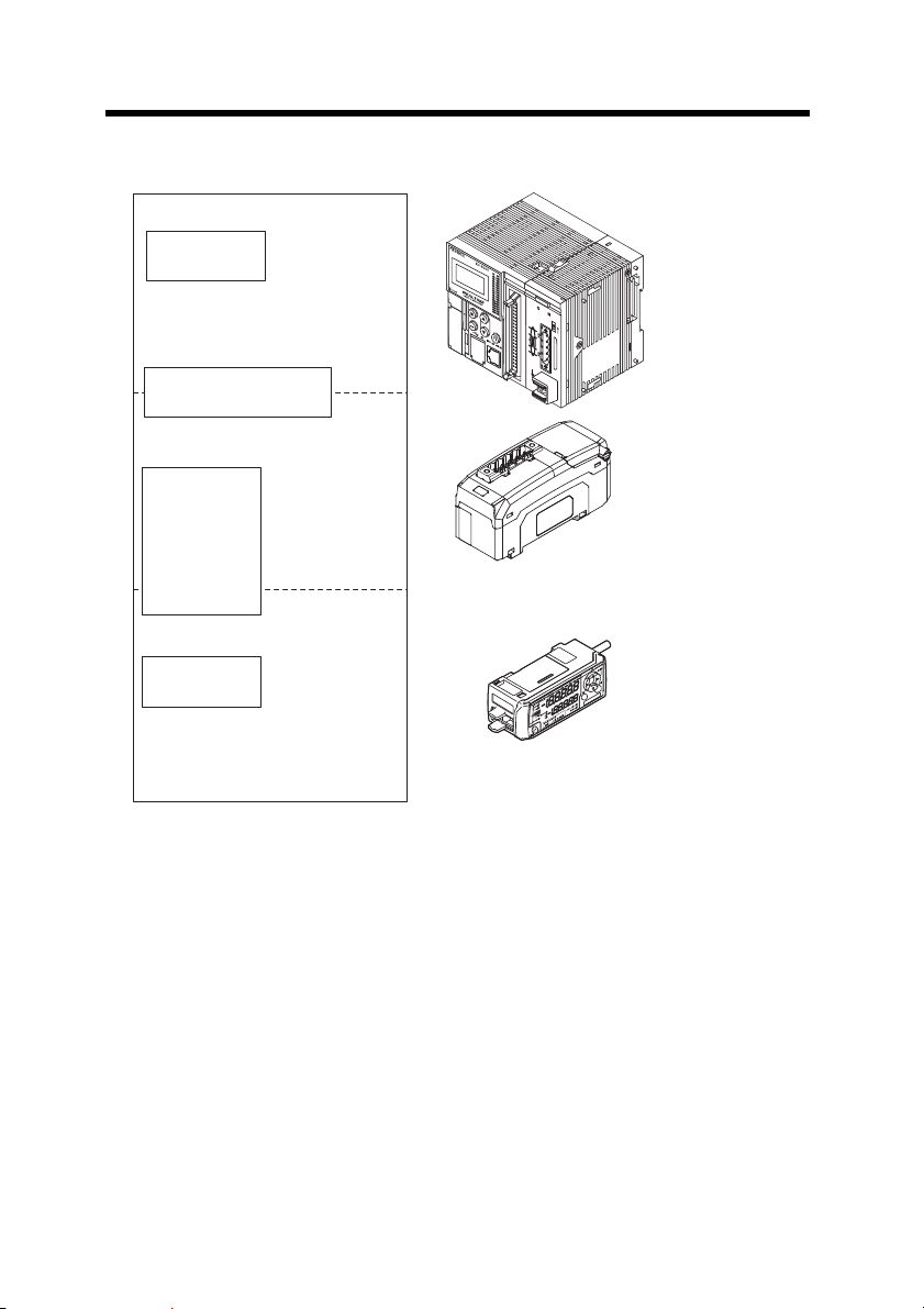
Relevant Manuals
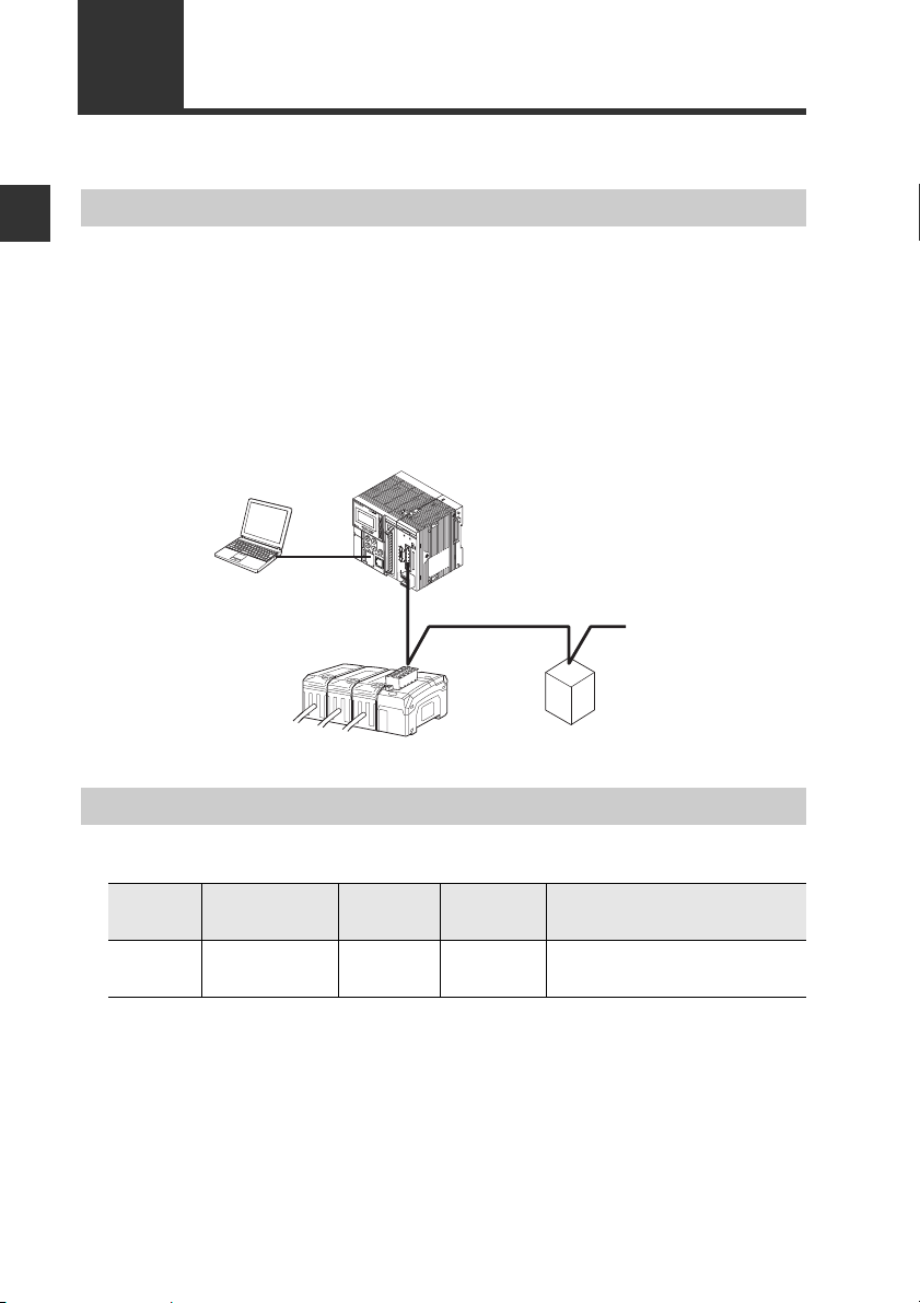
PLC CPU unit
DeviceNet master unit
DL-DN1 (This unit)
Manuals relevant
to CPU unit
Manuals relevant to
DeviceNet master unit
This manual
Manuals of sensor
amplifier main unit
Example:
・
FD-S series instruction manual
KV-DN20
MS
NS
ON
TERM.
Sensor amplifier
Example: KV-5000 user's manual
Example: KV-DN20 user's manual
The manuals relevant to this document are as follows:
4
- DeviceNet Compatible Network Unit DL-DN1 User’s Manual (FD-S) -
Page 7
Manual Organization
This chapter provides an overview of the DL-DN1
and describes its part names and functions.
Before Using
1
This chapter explains the procedures for
connecting sensor amplifiers to the DL-DN1
and how to configure the data link.
Connection and
Configuration
2
This chapter describes the configuration of the
memory linked to the DeviceNet master station and
provides communication time charts.
Communicating
with the FD-S
Series
3
4
5
This chapter describes the specifications
and dimensions of the DL-DN1.
Specifications
Provides the parameter list, as well as
troubleshooting instructions.
Appendix
1
2
3
4
5
- DeviceNet Compatible Network Unit DL-DN1 User’s Manual (FD-S) -
5
Page 8

Table of Contents
Safety Precautions ........................................................................................ 1
General Precautions ......................................................................... 1
Precautions for Use ........................................................................... 1
Notes on Regulations and Standards ............................................... 2
Relevant Manuals .......................................................................................... 4
Manual Organization ..................................................................................... 5
Table of Contents .......................................................................................... 6
Terms Used in This Document ..................................................................... 8
Chapter 1 Before Using
1-1 DL-DN1 Overview .............................................................................. 1-2
Overview ........................................................................................1-2
Types and Number of Connectable Sensor Amplifiers ..................1-2
1-2 Checking the Package Contents .....................................................1-3
Package Contents .......................................................................... 1-3
1-3 Names and Functions of Each Part .................................................1-4
Chapter 2 Connection and Configuration
2-1 Installation and Connection to Sensor Amplifiers .........................2-2
ID Number Assignments to Sensor Amplifiers ............................... 2-2
Installation and Connection to Sensor Amplifiers ...........................2-3
2-2 Wiring .................................................................................................2-6
Connecting to the DeviceNet .........................................................2-6
2-3 Configuring the Data Link ................................................................2-9
Configuring the Master Unit ...........................................................2-9
Configuring the DL-DN1 ...............................................................2-10
Chapter 3 Communicating with the FD-S series
3-1 Overview of DeviceNet Communication ......................................... 3-2
Data Communicated Using DeviceNet ...........................................3-2
Overview of Communication Methods ........................................... 3-3
3-2 I/O Communication ........................................................................... 3-4
Selecting the DL-DN1 Operating Mode .......................................... 3-4
Configuring the Operating Mode Setting Switch ............................3-5
Occupied Memory .......................................................................... 3-5
Device Maps ..................................................................................3-7
Communication Methods ............................................................. 3-14
3-3 Explicit Messaging ..........................................................................3-17
6
- DeviceNet Compatible Network Unit DL-DN1 User’s Manual (FD-S) -
Page 9

Table of Contents
Basic Formats of Explicit Messaging ........................................... 3-17
Issuing a Motion Command to a Sensor Amplifier ....................... 3-19
Reading/Writing Settings or Status of a Sensor Amplifier ............ 3-20
Locking Sensor Amplifiers ............................................................ 3-22
Command Parameter List ............................................................3-23
Chapter 4 Specifications
4-1 Specifications ....................................................................................4-2
4-2 Data Processing Times ....................................................................4-3
4-3 Dimensions ........................................................................................ 4-4
Chapter 5 Appendix
5-1 DeviceNet Device Profile .................................................................. 5-2
Device Profile ................................................................................. 5-2
5-2 Troubleshooting ................................................................................5-3
5-3 Index ................................................................................................... 5-6
- DeviceNet Compatible Network Unit DL-DN1 User’s Manual (FD-S) -
7
Page 10

Terms Used in This Document
This document uses the following terms:
Te r m Description
Sensor A sensor amplifier.
Master unit A DeviceNet master unit.
Slave unit A DeviceNet slave unit.
Main unit A sensor amplifier that has a power line and can operate
alone.
Expansion unit A sensor amplifier that does not have a power line and
must be connected to a main unit.
D-bus The name of KEYENCE's wiring-saving syste
amplifiers.
Supports FD-S Series colioris type digital flow sensors
and others.
PGM A mode in which DeviceNet node addresses c an be set by
software. Explicit messaging is used for setting the
addresses.
m for sensor
8
- DeviceNet Compatible Network Unit DL-DN1 User’s Manual (FD-S) -
Page 11

Before Using
This chapter provides an overview of the DL-DN1 and describes its
part names and functions.
1-1 DL-DN1 Overview .............................................. 1-2
1-2 Checking the Package Contents ........................ 1-3
1-3 Names and Functions of Each Part....................1-4
1
- DeviceNet Compatible Network Unit DL-DN1 User’s Manual (FD-S) -
1-1
Page 12
1-1
D-bus compatible sensor amplifier
PLC or other host device
(DeviceNet master unit)
DL-DN1 (This unit)
DeviceNet slave unit
KV-DN20
MS
NS
ON
TERM.
DL-DN1 Overview
1
Overview
Before Using
The DL-DN1 opera tes as a slave unit of DeviceNet communication. Using DeviceNet
communications, the sensor amplifiers and other units connected to the DL-DN1 can
transmit their ON/OFF control signals and current values as communication data to a
PLC or other equipment.
The DL-DN1 supports DeviceNet I/O communication (polling) and explicit messaging.
I/O polling enables data communi
messaging allows for reading/writing sensor amplifier parameters and issuing motion
commands to the sensor amplifiers.
System configuration example
Type s and Number of Connectable Sensor Amplifiers
cation without t
he need of a ladder program. Explicit
Number of Connectable Sensor Amplifiers
Name Amplifier form Main unit
FD-S
series*
DIN rail
mounting type
FD-SA1NA
FD-SA1PA
Expansion
unit
FD-SA2NA
FD-SA2PA4(1 main unit, 3 expansion units)
Maximum number of
connectable units
*Cannot be connected to a panel mounting type.
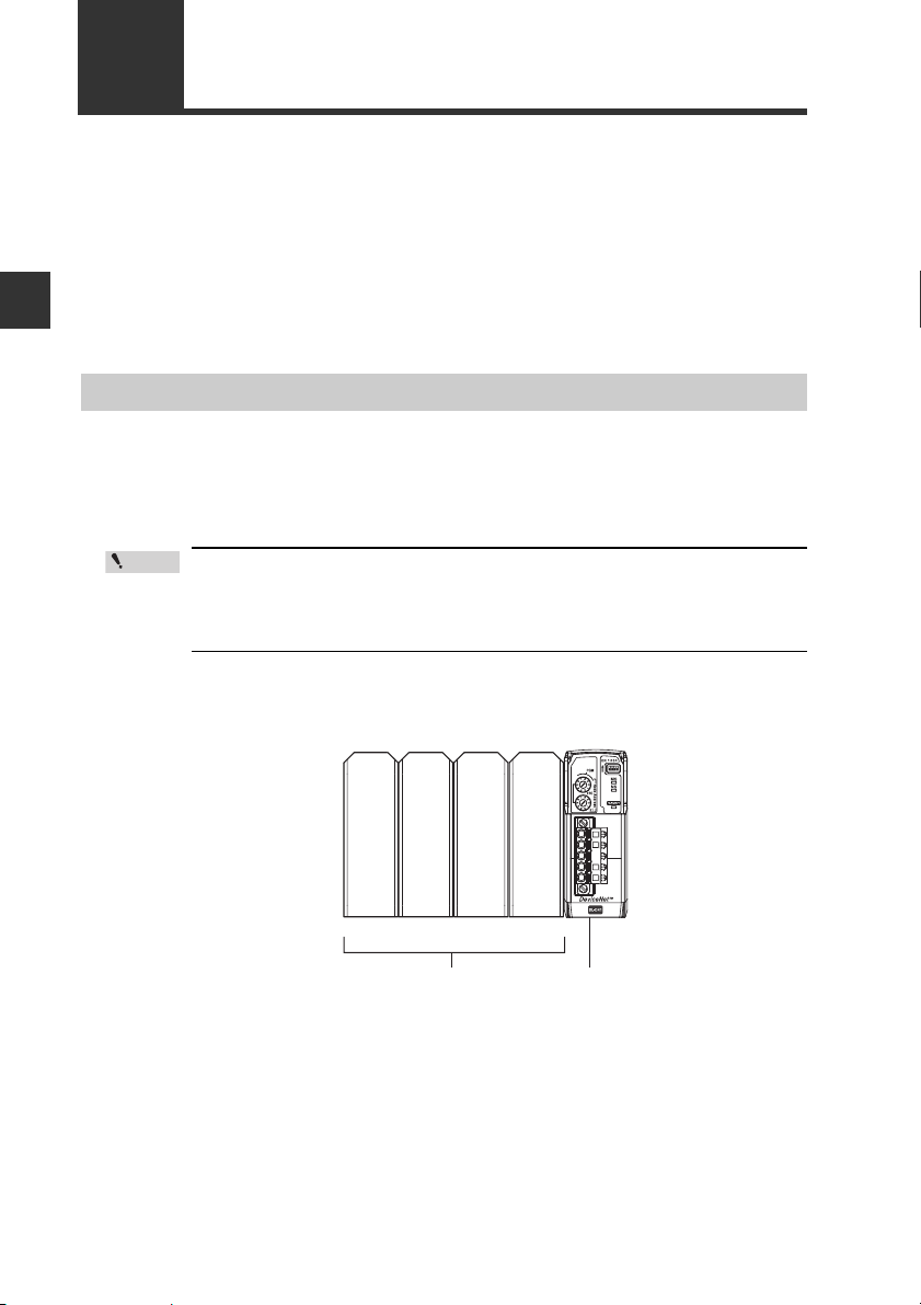
The DL-DN1 can connect to multiple sensor amplifiers (a single main unit and multiple
expansio
saving system for sensor amplifiers.
n units) which support D-Bus. "D-bus" is the name of KEYENCE's wiring-
Different types of sensor amplifiers with D-bus support can be connected to a single
DL-DN1 unit.
How many and what types of sensor amplifiers can be connected depends on the
sensor amplifiers or units to be connected. Please inquire for details.
1-2
- DeviceNet Compatible Network Unit DL-DN1 User’s Manual (FD-S) -
Page 13
1-2
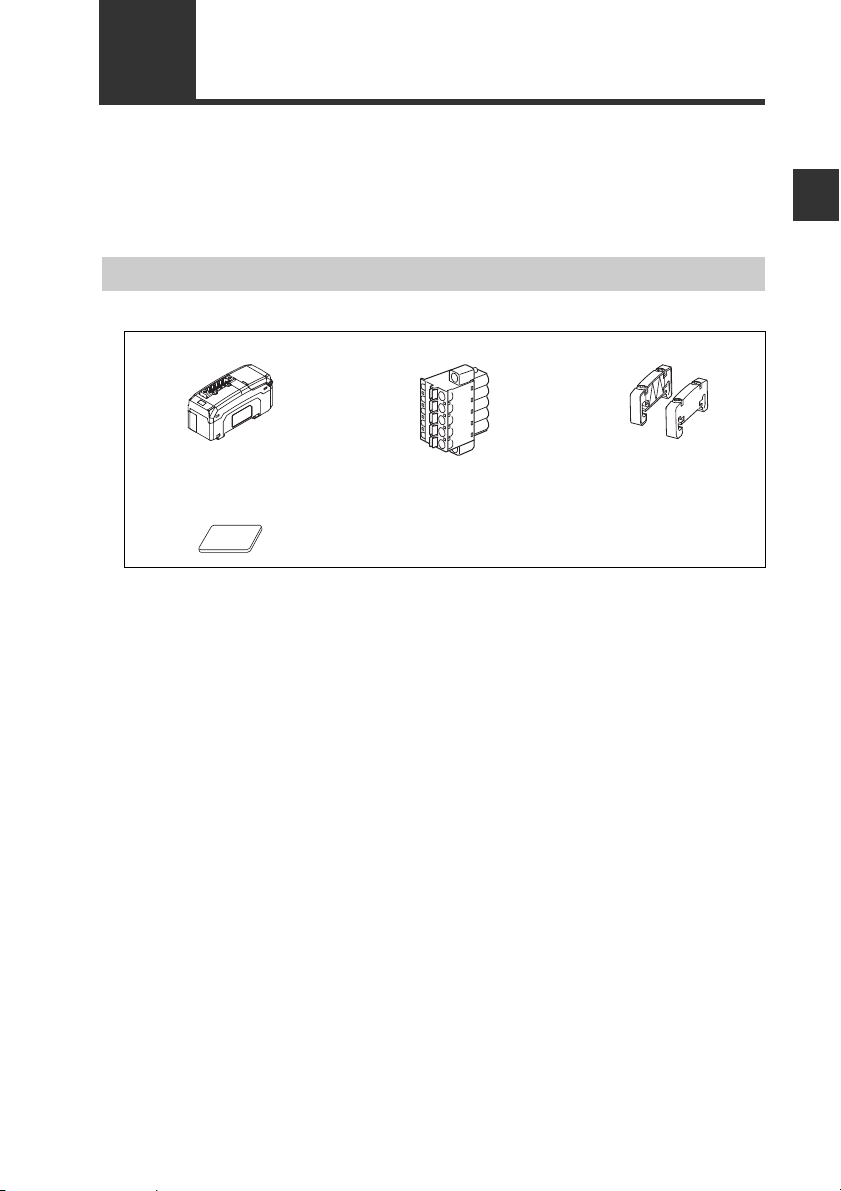
Before using the DL-DN1, make sure that the following equipment and accessories
are included in the package.
We have thoroughly inspected the package contents before shipment. However, in the
event of defective or broken items, contact your nearest KEYENCE office.
Package Contents
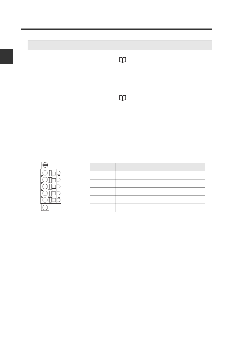
DL-DN1 main unit x 1 DeviceNet connector x 1 End unit x 2
Checking the Package Contents
1
Before Using
Expansion connector
sticker x 1
Instruction Manual x 1
- DeviceNet Compatible Network Unit DL-DN1 User’s Manual (FD-S) -
1-3
Page 14

1
(6) Sensor amplifier connector
(for DIN rail mounting type)
(8) DeviceNet connector
(2) Operating mode setting switch
(1) Address setting switch
(7) Sensor amplifier connector
(for panel mounting type
and large display type)
(4) Network status indicator (green/red)
(5) Sensor communication indicator (green/red)
(3) Module status indicator (green/red)
DL
DN1
20-30V DC, Class2
15JN
IND.CONT.EQ.
Point
1-3
Names and Functions of Each Part
This section describes the part names and functions of the DL-DN1.
Before Using
Item Description
(1)Address setting switch Sets the DeviceNet node address of the DL-DN1.
x10 : Ten's digit
x1 : One's digit
1-4
Setting range: 00 to 63
Default value: 63
When setting the node address of the DL-DN1 from
the DeviceNet master unit, set it in the range of 64 to
99. The DL-DN1 is switched to PGM mode.
When the DL-DN1 is set in the PGM mode
and the power is turned on, the address
of the DL-DN1 is the same as used when
the DL-DN1was started last time.
When the DL-DN1 in the factory default
setting is set to the PGM mode, the node
address of the DL-DN1 is 63. Do not start
multiple DL-DN1 units in factory default
setting in the PGM mode, as that will
result in a network error because of the
duplicate node addresses.
- DeviceNet Compatible Network Unit DL-DN1 User’s Manual (FD-S) -
Page 15
Item Description
Switch setting Operating mode
Occupied memory
IN area OUT area
3-output mode 8 byte 0 byte
5-output mode 12 byte 0 byte
"3-output + current value"
mode
14 to 70 byte 0 byte
"5-output + current value"
mode
18 to 74 byte 0 byte
Switch setting Operating mode
Occupied memory
IN area OUT area
No extended mode
--
External input mode
14 to 84 byte 6 to 10 byte
"External input +
BANK change"
mode
18 to 88 byte 10 to 14 byte
"External input +
setting value change" mode
22 to 96 byte 24 to 40 byte
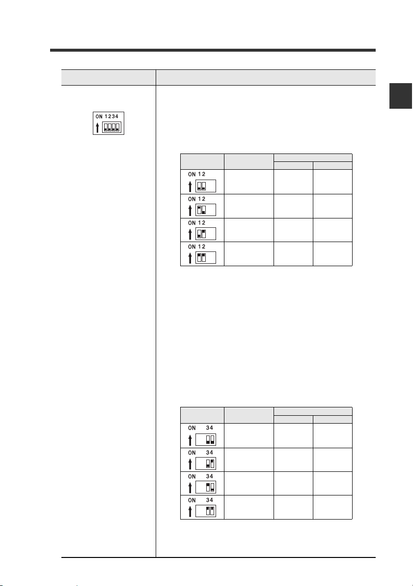
(2)Operating mode set-
ting switch
1-3 Names and Functions of Each Part
Sets the operating mode of the DL-DN1 in the DeviceNet.
The data that can be handled in remote I/O communica-
tion varies with each operating mode.
Basic mode
Use switch bits 1 and 2 to configure the basic mode.
Default value: 3-output mode
• The contents of output and current value vary depending on the sensor amplifiers to be connected.
Examples: 3
-level judgment output for 3-output mode;
5-level judgment output for 5-output mode. Current
value: comparator value.
• The size of occupied memory depends on the number
of amplifiers to be connected.
1
Before Using
Extended mode
Switch bits 3 and 4 can be set to add one of the following
extended functions to the basic mode.
Default value: No extended mode
- DeviceNet Compatible Network Unit DL-DN1 User’s Manual (FD-S) -
The size of occupied memory depends on the number of
amplifiers to be connected.
1-5
Page 16
1
Black
Blue
White
Red
Wire color Signal name Function
Black V -
Connects 0 VDC of the communication power supply.
BlueCAN_LCommunication signal (Low)
Bare wire SHIELD
Connects the shield of the DeviceNet cable.
White CAN_H Communication signal (High)
Red V +
Connects 24 VDC of the communication power supply.
1-3 Names and Functions of Each Part
Item Description
(3)Module status
indicator
Before Using
(4)Network status
indicator
(5)Sensor communica-
tion indicator
(6)Sensor amplifier
connector
(for DIN
rail mounting)
(7)Sensor amplifier
connector (for panel
mounting/large dis-
play)*
(8) DeviceNet connector Attach the DeviceNet cable to this connector.
When normal: Lit in green
For details, see "Troubleshooting" (page 5-3).
Indicates the status of communication between the DLDN1 and sensor amplifiers.
When normal: Lit in green
For details, see "Troubleshooting" (page 5-3).
Attach the sensor amplifier to this connector.
Attach the sensor amplifier to this connector.
When shipped from the factory, a protective sticker is
installed.
The optional expansion cable (OP-35361) is used for this
connection.
*Not used with the FD-S series.
1-6
- DeviceNet Compatible Network Unit DL-DN1 User’s Manual (FD-S) -
Page 17

Connection and Configuration
This chapter explains the procedures for connecting sensor
amplifiers to the DL-DN1 and how to configure the data link.
2-1 Installation and Connection to Sensor Amplifiers........ 2-2
2-2 Wiring .................................................................2-6
2-3 Configuring the Data Link...................................2-9
2
- DeviceNet Compatible Network Unit DL-DN1 User’s Manual (FD-S) -
2-1
Page 18
2
Point
ID number
01
Main
unit
Expansion
unit
Expansion
unit
Expansion
unit
02
...
04
Sensor amplifier DL-DN1
2-1
This section provides the procedures for installing the DL-DN1 and connecting to
sensor amplifiers.
The DL-DN1 can be connected with the expansion units of sensor amplifiers which
support D-bus. ("D-bus" is the name of KEYENCE's wiring-saving system for sensor
amplifiers.) How many sensor amplifiers can be connected depends on the sensor
amplifiers or units to be connected. For specifi
Connection and Configuration
manual of each sensor amplifier.
Installation and Connection to Sensor Amplifiers
c numbers of connections, refer to the
ID Number Assignments to Sensor Amplifiers
When connecting the DL-DN1 to a sensor amplifier which can be configured with
expansion units, the main unit will be assigned ID number 01, with the expansion units
assigned ID numbers of 02 to 04.
• The ID number assignments to sensor amplifiers cannot be
changed by the user.
• In this manual, ID number 01 to ID number 04 are denoted as ID 01
to ID 04, respectively.
2-2
- DeviceNet Compatible Network Unit DL-DN1 User’s Manual (FD-S) -
Page 19

2-1 Installation and Connection to Sensor Amplifiers
(1)
(2)
(3)
Installation and Connection to Sensor Amplifiers
Mounting on a DIN rail
Align the claw on the bottom of the amplifier with the DIN rail. While push-
1
ing the amplifier in the direction of arrow (1), press down in the direction
of arrow (2).
To remove the DL-DN1, raise the main unit in the direction of arrow (3)
2
while pushing it the direction of arrow (1).
2
Connection and Configuration
- DeviceNet Compatible Network Unit DL-DN1 User’s Manual (FD-S) -
2-3
Page 20
2
Point
2-1 Installation and Connection to Sensor Amplifiers
Procedures for connecting to sensor amplifiers
The DeviceNet compatible communication unit DL-DN1 must be connected to sensor
amplifiers before it can function.
Make sure that the power to the sensor amplifier is off before starting to
NOTICE
connect the DeviceNet compatible communication unit, DL-DN1. Performing the procedure with the power on may damage the DL-DN1.
Connection and Configuration
1
2
For the instructions on connecting additional sensor amplifiers, refer
to the instruction manual of the sensors amplifiers.
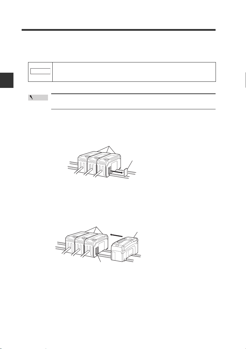
Remove the expansion protective cover from the sensor amplifier to be
connected.
Sensor amplifier
Expansion protective cover
Install the DeviceNet compatible communication unit, DL-DN1, on the DIN
rail and connect to the sensor amplifier.
Ensure a tight connection, leaving no space between the DeviceNet compatible
communication unit, DL-DN1, and the sensor amplifier.
Sensor amplifier
DeviceNet compatible communication
unit DL-DN1
2-4
Connector
- DeviceNet Compatible Network Unit DL-DN1 User’s Manual (FD-S) -
Page 21

2-1 Installation and Connection to Sensor Amplifiers
NOTICE
Sensor amplifier connector
DeviceNet compatible
communication unit DL-DN1
NOTICE
Make sure that the sensor amplifier connector (for DIN rail mounting
type) is not askew on the side face of the DeviceNet compatible communication unit, DL-DN1, as shown below. If the connector is askew, the DLDN1 may become damaged when connected to the sensor amplifier.
Mount the supplied end units (OP-26751: a set of two pieces) on the outer
3
side faces of the amplifier and the DeviceNet compatible communication
unit, DL-DN1. Then, fix the end units with the screws on the top of each
end unit (2 points x 2 units). (Tightening torque: 0.6N•m or less)
Mount the end units in the same way as the DeviceNet compatible communica-
tion unit, DL-DN1.
End unit
2
Connection and Configuration
End unit
Press the DeviceNet compatible communication unit DL-DN1 into full
engagement with the sensor amplifier. If the DL-DN1 is not correctly connected, it may be damaged when the power is turned on.
- DeviceNet Compatible Network Unit DL-DN1 User’s Manual (FD-S) -
2-5
Page 22
2
Point
Point
2-2
This section describes how to wire the DL-DN1.
Refer also to the DeviceNet Installation Manual published by ODVA.
Connection and Configuration
Connecting to the DeviceNet
Use the following procedure to connect the DL-DN1 to the DeviceNet.
Recommended cables
For connection between the DL-DN1 and the DeviceNet, use a dedicated DeviceNet
cable conforming to the DeviceNet specifications or a dedicated flat cable.
Trimming the cable
Wiring
Turn off the power before wiring.
Do not use non-dedicated cables, as this may inhibit proper communication.
2-6
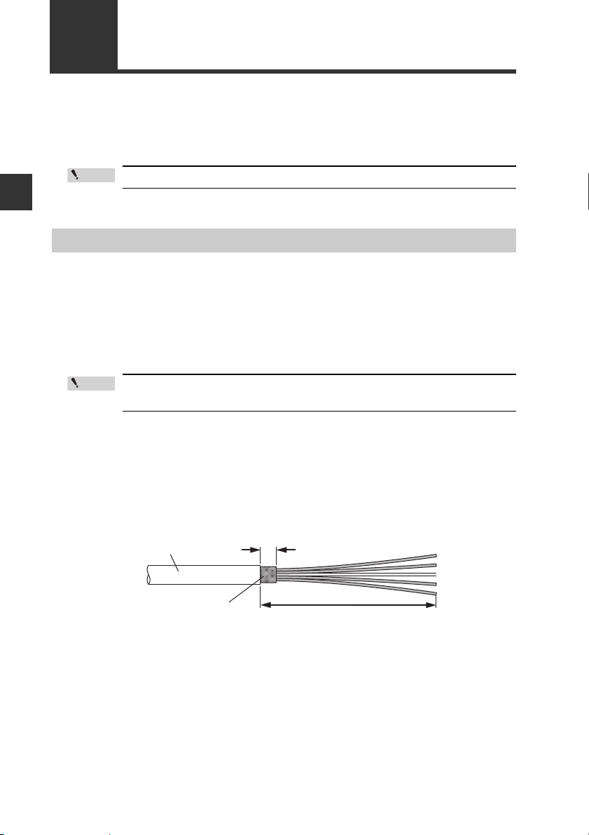
Strip the cable sheath.
1
Strip approximately 70 mm of cable sheath.
Make sure that the bare part of the shield braid is 6 mm or shorter.
Sheath
Shield braid
- DeviceNet Compatible Network Unit DL-DN1 User’s Manual (FD-S) -
6 mm or shorter
Approx. 70 mm
Page 23
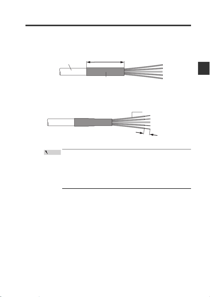
Install a shrinkable tube.
Approx. 40mm
Shrinkable tube
Sheath
Approx. 10mm
Sheathed conductor
Point
2
Cover the exposed sheathed conductors and the sheath using a shrinkable
tube approximately 40 mm long.
Strip the sheathed conductors.
3
Strip approximately 10 mm of sheath from the end of each conductor.
• If you are using solderless terminals, perform cable wiring/
trimming appropriately to suit the specifications of the particular terminals.
Recommended solderless terminals: Phoenix Contact's A/AI
Series
• Do not perform soldering (pre-soldering) on the trimmed end
of the cable.
2-2 Wiring
2
Connection and Configuration
- DeviceNet Compatible Network Unit DL-DN1 User’s Manual (FD-S) -
2-7
Page 24

2
Black
Blue
White
Red
2-2 Wiring
Connecting the cable
Use the following procedures to wire to the DeviceNet connector supplied with the DLDN1.
Connect the trimmed cable to the DeviceNet connector.
1
Insert the cable completely.
Connection and Configuration
Wire color Signal name Function
Black V -
BlueCAN_LCommunication signal (Low)
Bare wire SHIELD
White CAN_H Communication signal (High)
Red V +
Connects 0 VDC of the communication power supply.
Connects the shield of the DeviceNet cable.
Connects 24 VDC of the communication power supply.
2-8
Attach the DeviceNet connector to the DL-DN1.
2
Plug the connector into the DL-DN1 and secure it down with the screws on each
end. (Tightening torque: 0.2 to 0.3 N•m)
- DeviceNet Compatible Network Unit DL-DN1 User’s Manual (FD-S) -
Page 25

2-3
Point
Reference
Point
Reference
Use the following procedure to connect the DL-DN1 to the DeviceNet system.
Configuring the Data Link
This manual covers only the functions and settings of a DeviceNet master
unit which are required for communication with the DL-DN1. For the functions
and settings related to the communication between the DeviceNet master unit
and CPU unit, refer to the manuals shipped with your master unit or CPU unit.
Configuring the Master Unit
The following configurations are required to connect the DL-DN1 to the DeviceNet
master unit.
Slave attribute settings
Configure the master unit with the communication form, I/O size, and other
information about the slave units. For this purpose, the EDS file for the DL-DN1 can
be imported into the configuration software of the master unit.
The EDS file can be downloaded from the KEYENCE web site:
http://www.keyence.com
2
Connection and Configuration
Memory allocation settings
Configure the memory areas required for exchanging data th
co
mmunication. Do this using the configuration software of the master unit.
• The memory allocations must be reconfigured if the number of
connected sensors is changed, because the memory area
reserved in the DL-DN1 may change.
• Cautions for connecting the Keyence master unit KV-DN20
Assign the memory allocation start address either to odd-numbered addresses or to even-numbered addresses according to
operating modes of the DL-DN1 (refer to page 2-10). The current
value may not be read out correctly if the assignment is not proper.
Assign to odd-numbered addresses:
3-output + current value (no extended) mode
5-output + current value (no extended) mode
Assign to even-numbered addresses:
Operating modes other than the above
Where multiple slave units are connected, the memory allocation for each
slave unit is done automatically, based on the specified starting address.
The allocation information for each slave unit can be checked using
DeviceNet configuration software.
- DeviceNet Compatible Network Unit DL-DN1 User’s Manual (FD-S) -
rough I/O
2-9
Page 26

2
Operating mode setting switch
Address setting switch
Point
2-3 Configuring the Data Link
Configuring the DL-DN1
Use the following procedures to configure the data link of the DL-DN1.
Connection and Configuration
Setting the node address
Using the address setting switch, set the DeviceNet node address to be assigned to
the DL-DN1.
• Default value: 63
• Setting range: 00 to 63
When setting the node address of the DL-DN1 from the DeviceNet master unit, set it
in the range of 64 to 99. The DL-DN1 enters PGM mode.
Selecting an operating mode
Select the desired operating mode of the DL-DN1 using the operating mode setting
switch.
The data that can be ha ndled in I/O communication varies with each operating mode.
2-10
When the DL-DN1 is set in the PGM mode and the power is turned on,
the address of the DL-DN1 is the same as used when the DL-DN1was
started previously.
When the DL-DN1, in the factory default setting, is set to PGM mode,
the node address of the DL-DN1 is 63. Do not start multiple DL-DN1
units in factory default setting in the PGM mode, as that will result in
a network error because of the duplicate node addresses.
- DeviceNet Compatible Network Unit DL-DN1 User’s Manual (FD-S) -
Page 27

Basic mode
Point
Reference
Use switch bits 1 and 2 to configure the basic mode.
Switch setting Operating mode
3-output mode 8 byte 0 byte
Occupied memory
IN area OUT area
2-3 Configuring the Data Link
5-output mode 12 byte 0 byte
"3-output + current value"
mode
"5-output + current value"
mode
14 to 70 byte 0 byte
18 to 74 byte 0 byte
Default value: 3-output mode
• The output content depends on the sensor amplifiers to be connected.
Examples: 3-level judgment output in 3-output mode; 5-level judgment output in 5output mode
• The size of the occupied memory depends on the number of amplifiers to be connected.
Extended mode
Switch bits 3 and 4 can be set to add one of the following extended functions to the
basic mode.
Switch setting Operating mode
No extended mode
External input mode
"External input +
BANK change"
mode
"External input +
setting value change" mode
Occupied memory
IN area OUT area
--
14 to 84 byte 6 to 10 byte
18 to 88 byte 10 to 14 byte
22 to 96 byte 24 to 40 byte
2
Connection and Configuration
Default value: No extended mode
The size of the occupied memory depends on the number of amplifiers to be
connected and the setting of the basic mode.
Each switch should be set before turning on the power. If any setting
is changed while the DL-DN1 is operating, the new setting will not be
applied until the power is turned on again. (The module status indicator flashes in red.)
The baud rate is set automatically to the value set on the DeviceNet master
unit.
- DeviceNet Compatible Network Unit DL-DN1 User’s Manual (FD-S) -
2-11
Page 28

2
2-3 Configuring the Data Link
MEMO
Connection and Configuration
2-12
- DeviceNet Compatible Network Unit DL-DN1 User’s Manual (FD-S) -
Page 29

Communicating with the FD-S series
This chapter describes the configuration of the memory linked to the
DeviceNet master unit and provides communication time charts.
3-1 Overview of DeviceNet Communication.............3-2
3-2 I/O Communication............................................. 3-4
3-3 Explicit Mess a ging............................................ 3-17
3
- DeviceNet Compatible Network Unit DL-DN1 User’s Manual (FD-S) -
3-1
Page 30

3
3-1
Overview of DeviceNet Communication
The DL-DN1 operates as a slave unit of a DeviceNet system, with support for I/O
communication (polling) and explicit messaging. This section outlines the type of data
that the DL-DN1 can communicate using DeviceNet and how it is communicated.
Data Communicated Using DeviceNet
The master unit of the DeviceNet system and the DL-DN1 are linked as shown below.
Sensor amplifier
Output
Communicating with the FD-S series
DeviceNet
master unit
IN are
OUT area
IN are
OUT area
I/O
communication
I/O
communication
Explicit messaging
DL-DN1
Output
Current value
Error information
Request to change setting value
Changed setting value
Exteral input
Output
Current value
・・・・・・
Error information
・・・・・・
・・・・・・
Setting value
Exteral input
・・・・・・
・・・・・・
Output
Current value
・・・・・・
Errror information
・・・・・・
・・・・・・
Setting value
Exteral input
・・・・・・
・・・・・・
Current value
・・・・・・
Errror information
・・・・・・
・・・・・・
Setting value
Exteral input
・・・・・・
・・・・・・
3-2
Read/write parameters
- DeviceNet Compatible Network Unit DL-DN1 User’s Manual (FD-S) -
Page 31

3-1 Overview of DeviceNet Communication
Overview of Communication Methods
The master unit of the DeviceNet system can use the following functions:
Function of sensor
Communication Methods.
amplifier
Read status
Read output
Read current value
Execute external input*
Rewrite setting value
Motion command
Read current value,
setting, and status
Read data with decimal point
information
Rewrite setting
Lock all
I/O Communication
p. 3-4
Ye s
No
Explicit Messaging
p. 3-17
Ye s
* When you use this function through explicit messaging, use a command parameter
of each function assigned for external inputs (1 to 5). For details, refer to
"Command Parameter List for FD-S Series" (page 3-25).
I/O Communication
• The output signal, comparator value, and error status of sensor amplifiers can be
communicated without the need of a ladder program.
• By using the IN and OUT areas as handshake signals, the master unit can execute
external inputs to the sensor amplifier or change setting values.
"I/O Communication" (page 3-4)
Explicit Messaging
The master unit can use explicit messaging commands to directly read
parameter values of
sensor amplifiers. All functions that can be executed on sensor
amplifiers are available through explicit messaging.
"Explicit Messaging" (page 3-17)
3
Communicating with the FD-S series
/write
- DeviceNet Compatible Network Unit DL-DN1 User’s Manual (FD-S) -
3-3
Page 32

3-2
Output data
Data here will be
reflected in the master unit.
Input data
Data here has been
output from the master unit.
DeviceNet master unit DL-DN1 sensor amplifier
IN area
OUT area
I/O communication
I/O communication
I/O Communication
The device map varies depending on the operating mode of the DL-DN1. Select an operating
mode suited for the functions of the sensor amplifiers to be used, before accessing each device.
The memory in the DeviceNet master unit is linked to the buffer memory in the DLDN1 as shown below.
3
Communicating with the FD-S series
Selecting the DL-DN1 Operating Mode
Select the DL-DN1 operating mode to suit the functions of the sensor amplifiers to be used.
The DeviceNet device configuration and the data available for I/O communication
vary, depending on the selected operating mode of the DL-DN1 and the number of
connected sensor a mplifiers. An appropriate operating mode should be determined
by considering the memory occupied and the data that can be co
"Occupied Memory" (page 3-5)
Available function of sensor
amplifier
Read status
Read outputs
1 - 5
Read current value
(instantaneous flow rate)*1
External
inputs
1 - 5
Change bank number
Rewrite setting value*1 No Yes No Yes No Yes No Yes 3-12 3-16
*1 It is possible to read instantaneous flow rate or rewrite setting value regardless
Output 1
Output 2
Output 3
(Not used)
(Not used)
Integration reset
Flow rate hold reset
Zero adjustment
Temperature
hold reset
(Not used)
3-output
3-input
Bank
-
-
Ye s Ye s
No No
No Yes No Yes 3-10 3-15
No Yes No Yes
No No
*2 No
No
Operating mode of DL-DN1
3-output + current value
3-input
Setting
value
-
-
*2 No
No
5-output
5-input
Setting
value
Bank
Bank
-
-
Ye s Ye s
No Yes No Yes 3-11 3-15
*2 No
No
of the detection mode setting.
*2 This is not available with the FD-S series.
3-4
- DeviceNet Compatible Network Unit DL-DN1 User’s Manual (FD-S) -
mmunicate
5-output + current value
Setting
value
-
No
5-input
Setting
value
Bank
-
*2 No - -
d.
Device maps
3-7 3-14
3-9 3-14
Communication
method
Page 33

3-2 I/O Communication
DIP switch Operating mode
1 2 3 4 Output
Current
value
External
input
Bank
change
Setting value
rewrite
OFF OFF OFF OFF
3-output
No
No
No
No
OFF ON OFF OFF Ye s
OFF OFF OFF ON No
3-input
OFF ON OFF ON Ye s
OFF OFF ON OFF No
*
OFF ON ON OFF Ye s
OFF OFF ON ON No
No Ye s
OFF ON ON ON Ye s
ON OFF OFF OFF
5-output
No
No
No
No
ON ON OFF OFF Ye
s
ON OFF OFF ON No
5-input
ON ON
OFF ON Ye s
ON OFF ON OFF No
*
ON ON ON OFF Yes
ON OFF ON ON No
No Ye s
ON ON ON ON Ye s
3-output
No extended mode Yes - -
3-input - Yes Ye s
Change setting value - - Ye s
Area IN OUT IN OUT IN OUT
Number of sensor amplifi ers 1-4 8 0 14 6 22 24
(bytes)
Configuring the Operating Mode Setting Switch
Configure the operating mode setting switch to suite the operating mode to be used.
"Configuring the Operating Mode Setting Switch" (page 3-5)
*This is not available with the FD-S series.
3
Communicating with the FD-S series
Occupied Memory
The memory size occupied by the DL-DN1 varies with the selected operating mode
and the number of connected sensor amplifiers.
3-output mode
- DeviceNet Compatible Network Unit DL-DN1 User’s Manual (FD-S) -
3-5
Page 34

3
3-output + monitor
No extended mode Yes - -
3-input - Yes Ye s
Setting value rewrite - - Ye s
Area IN OUT IN OUT IN OUT
Number of sensor amplifi ers
1 14
0
20
6
28
24
2 18 24 32
3 22 28 36
4 26 32 40
(bytes)
5-output
No extended mode Yes - -
5-input - Yes Ye s
Setting value rewrite - - Ye s
Area IN OUT IN OUT IN OUT
Number of sensor amplifi ers 1-4 12 0 22 10 34 40
(bytes)
3-2 I/O Communication
"3-output + current value" mode
Communicating with the FD-S series
5-output mode
"5-output + current value" mode
5-output + current value
Number of sensor amplifi ers
No extended mode Yes - -
5-input - Yes Ye s
Setting value rewrite - - Ye s
Area IN OUT IN OUT IN OUT
1 18
2 22 32 44
3 26 36 48
4 30 40 52
28
0
40
10
40
(bytes)
3-6
- DeviceNet Compatible Network Unit DL-DN1 User’s Manual (FD-S) -
Page 35

3-2 I/O Communication
Device
(DEC)
Name
Bit 7 Bit 6 Bit 5 Bit 4 Bit 3 Bit 2 Bit 1 Bit 0
Bit 15 Bit 14 Bit 13 Bit 12 Bit 11 Bit 10 Bit 9 Bit 8
n Status
Reserved Reserved Reser ved
Error ID
number
(MSB)
Error ID
number
Error ID
number
Error ID
number
Error ID
number
(LSB)
Error state Reser ved
Sensor
ready
Error code
(MSB)
Error code Error code Error code
Error code
(LSB)
Device Maps
The device map varies depending on the operating mode of the DL-DN1.
Access each device in a manner suitable for the selected operating mode.
"Status" (page 3-7)
"Output" (page 3-9)
"Current value (instantaneous flow rate)" (page 3-10)
"External input" (page 3-11)
"Rewrite setting value" (page 3-12)
Status
IN area
n: The first device number assigned to the DL-DN1
3
Communicating with the FD-S series
Status details
Name Description Reading range
Error status
Sensor ready
Error ID number
Error code
An error occurred with the DL-DN1 or sensor amplifier, or the
DL-DN1 is not communicating properly with the sensor amplifier.
If an error exists, the error ID number and error code are stored.
The sensor amplifier has started and is ready. 0: Starting
The error ID number is stored in the range of bit 0 (LSB) to bit 4
(MSB).
The error code is stored in the range of bit 8 (LSB) to bit 12
(MSB).
- DeviceNet Compatible Network Unit DL-DN1 User’s Manual (FD-S) -
0: No Error
1: Error
1: Ready
"Error information list"
(page 3-8)
3-7
Page 36

3
3-2 I/O Communication
Error information list
Error ID
number
(HEX)
00h
Communicating with the FD-S series
nnh
(01h -
0Fh)
1Dh
1Fh - No error - -
Error
code
(HEX)
01h Initialization error Error encountered during initial-
04h Mixed connection error A foreign sensor amplifier (i.e.,
06h Number-of-units error More sensor amplifiers are con-
01h Error 1 for sensor amplifier of
02h Error 2 for sensor amplifier of
03h Error 3 for sensor amplifier of
04h Error 4 for sensor amplifier of
05h Error 5 for sensor amplifier of
06h Error 6 for sensor amplifier of
07h Error 7 for sensor amplifier of
08h Error 8 for sensor amplifier of
09h Error 9 for sensor amplifier of
0Ah Error 10 for sensor amplifier of
0Bh Error 11 for sensor amplifier of
0Ch Error 12 for sensor amplifier of
02h/
04-07h
03h Model error There is a sensor amplifier con-
Description Cause Corrective action
ization.
one that is not compatible) is
connected.
nected than are permitted.
ID number nn
ID number nn
ID number nn
ID number nn
ID number nn
ID number nn
ID number nn
ID number nn
ID number nn
ID number nn
ID number nn
ID number nn
System error An error occurred in the internal
(Not used)
Head connection error
Overcurrent Error
EEPROM Error
No flow error
Backflow error
(Not used)
(Not used)
(Not used)
Drive gain error
Te m p er ature low error
Te m p er ature high error
system.
nected that is incompatible with
the DL-DN1.
Check the number of connected sensor amplifiers and
the connection to the sensor
amplifiers, and then cycle
power. If the error remains,
contact your nearest sales
office.
Remove the foreign sensor
amplifier.
Check the number of connected sensor amplifiers.
Refer to the FD-S series
instruction manual.
Check the connection to the
sensor, and then cycle power. If
the error can not be corrected,
contact your nearest sales
office.
Connect a sensor amplifier of a
compatible model.
3-8
- DeviceNet Compatible Network Unit DL-DN1 User’s Manual (FD-S) -
Page 37

3-2 I/O Communication
Device
(DEC)
Name
Bit 7 Bit 6 ··· Bit 1 Bit 0
Bit 15 Bit 14 ··· Bit 9 Bit 8
n+1 Output 1
ID08 ID07 ··· ID02 ID01
Reserved ID15 ··· ID10 ID09
n+2 Output 2
ID08 ID07 ··· ID02 ID01
Reserved ID15 ··· ID10 ID09
n+3 Output 3
ID08 ID07 ··· ID02 ID01
Reserved ID15 ··· ID10 ID09
Device
(DEC)
Name
Bit 7 Bit 6 ··· Bit 1 Bit 0
Bit 15 Bit 14 ··· Bit 9 Bit 8
n+1 Output 1
ID08 ID07 ··· ID02 ID01
Reserved ID15 ··· ID10 ID09
n+2 Output 2
ID08 ID07 ··· ID02 ID01
Reserved ID15 ··· ID10 ID09
n+3 Output 3
ID08 ID07 ··· ID02 ID01
Reserved ID15 ··· ID10 ID09
n+4 (Not used)
ID08 ID07 ··· ID02 ID01
Reserved ID15 ··· ID10 ID09
n+5 (Not used)
ID08 ID07 ··· ID02 ID01
Reserved ID15 ··· ID10 ID09
Output
Sensor amplifier ID numbers 01 to 04 are assigned to bits 0 to 3, respectively.
For details of communication methods, see "Reading an output from a sensor
amplifier" (page 3-14).
3-output mode
IN area
n: The first device number assigned to the DL-DN1
The device assignments are the same for all 3-output modes including extended
modes.
All 5-output modes
IN area
3
Communicating with the FD-S series
n: The first device number
The device assignments are the same for all 5-output modes including extended
modes.
assigned to the DL-DN1
- DeviceNet Compatible Network Unit DL-DN1 User’s Manual (FD-S) -
3-9
Page 38

3
Device (DEC)
Name
Bit 7 Bit 6 ··· Bit 1 Bit 0
No extended
mode
External input
External input +
Setting value rewrite
Bit 15 Bit 14 ··· Bit 9 Bit 8
n+4 n+7 n+11 Current value property
ID08 ID07 ··· ID02 ID01
Reserved
ID15 ··· ID10 ID09
n+5-6 n+8-9 n+12-13 Current Value ID01
Outputs the current value of sensor
amplifi er (ID**).(4-byte signed
integer)
Occupies a memory area
proportional to the number of
connected sensor amplifi ers.
n+7-8 n+10-11 n+14-15 Current Value ID02
n+9-10 n+12-13 n+16-17 Current Value ID03
n+11-12 n+14-15 n+18-19 Current Value ID04
Device (DEC)
Name
Bit 7 Bit 6 ··· Bit 1 Bit 0
No extended
mode
External
input
External input +
Setting value rewrite
Bit 15 Bit 14 ··· Bit 9 Bit 8
n+6 n+11 n+17
Current value
property
ID08 ID07 ··· ID02 ID01
Reserved
ID15 ··· ID10 ID09
n+7-8 n+12-13 n+18-19 Current Value ID01 Outputs the current value of sensor
amplifi er (ID**).(4-byte signed integer)
Occupies a memory area proportional to
the number of connected sensor amplifi ers.
n+9-10 n+14-15 n+20-21 Current Value ID02
n+11-12 n+16-17 n+22-23 Current Value ID03
n+13-14 n+18-19 n+24-25 Current Value ID04
3-2 I/O Communication
Current value (instantaneous flow rate)
The assigned positions for current values vary with different operating modes.
For details of communication methods, see "Reading current values
(instantaneous flow rate) from sensor amplifiers" (page 3-15).
"3-output + current value" mode
IN area
Communicating with the FD-S series
n: The first device number assigned to the DL-DN1
"5-output + current value" mode
IN area
n: The first device number assigned to the DL-DN1
3-10
- DeviceNet Compatible Network Unit DL-DN1 User’s Manual (FD-S) -
Page 39

3-2 I/O Communication
Device
(DEC)
Name
Bit 7 Bit 6 ··· Bit 1 Bit 0
Bit 15 Bit 14 ··· Bit 9 Bit 8
m Integration reset request
ID08 ID07 ··· ID02 ID01
Reserved ID15 ··· ID10 ID09
m+1
Flow rate hold reset
request
ID08 ID07 ··· ID02 ID01
Reserved ID15 ··· ID10 ID09
m+2 Zero adjustment request
ID08 ID07 ··· ID02 ID01
Reserved ID15 ··· ID10 ID09
Device
(DEC)
Name
Bit 7 Bit 6 ··· Bit 1 Bit 0
Bit 15 Bit 14 ··· Bit 9 Bit 8
n+4 Integration reset response
ID08 ID07 ··· ID02 ID01
Reserved ID15 ··· ID10 ID09
n+5
Flow rate hold reset
response
ID08 ID07 ··· ID02 ID01
Reserved ID15 ··· ID10 ID09
n+6 Zero adjustment response
ID08 ID07 ··· ID02 ID01
Reserved ID15 ··· ID10 ID09
Device
(DEC)
Name
Bit 7 Bit 6 ··· Bit 1 Bit 0
Bit 15 Bit 14 ··· Bit 9 Bit 8
m Integration reset request
ID08 ID07 ··· ID02 ID01
Reserved ID15 ··· ID10 ID09
m+1
Flow rate hold reset
request
ID08 ID07 ··· ID02 ID01
Reserved ID15 ··· ID10 ID09
m+2 Zero adjustment request
ID08 ID07 ··· ID02 ID01
Reserved ID15 ··· ID10 ID09
m+3
Temperature hold reset
request
ID08 ID07 ··· ID02 ID01
Reserved ID15 ··· ID10 ID09
m+4 Reserved
ID08 ID07 ··· ID02 ID01
Reserved ID15 ··· ID10 ID09
External input
Sensor amplifier ID numbers 01 to 04 are assigned to bits 0 to 3, respectively.
For details of communication methods, see "Entering an external input into a
sensor amplifier" (page 3-15).
3-output mode
OUT area
m: The first device number assigned to the DL-DN1
IN area
3
Communicating with the FD-S series
n: The first device number assigned to the DL-DN1
The device assignments are the same for all 5-output modes including extended
modes.
5-output mode
OU
T area
e first device number assigned to the DL-DN1
m: Th
- DeviceNet Compatible Network Unit DL-DN1 User’s Manual (FD-S) -
3-11
Page 40

3
Device
(DEC)
Name
Bit 7 Bit 6 ··· Bit 1 Bit 0
Bit 15 Bit 14 ··· Bit 9 Bit 8
n+6 Integration reset response
ID08 ID07 ··· ID02 ID01
Reserved ID15 ··· ID10 ID09
n+7
Flow rate hold reset
response
ID08 ID07 ··· ID02 ID01
Reserved ID15 ··· ID10 ID09
n+8 Zero adjustment response
ID08 ID07 ··· ID02 ID01
Reserved ID15 ··· ID10 ID09
n+9
Temperature hold reset
response
ID08 ID07 ··· ID02 ID01
Reserved ID15 ··· ID10 ID09
n+10 Reserved
ID08 ID07 ··· ID02 ID01
Reser
ved ID15 ··· ID10 ID09
3-2 I/O Communication
IN area
Communicating with the FD-S series
n: The first device number assigned to the DL-DN1
The device assignments are the same for all 5-output modes including extended
modes.
Rewrite setting value
Sensor amplifier ID numbers 01 to 04 are assigned to bits 0 to 3, respectively.
For details of communication methods, see "Rewriting a Setting Value of a Sensor
Amplifier" (page 3-16).
3-output mode
OUT area
Device
(DEC)
Request to rewrite
m+3
instantaneous flow rate
setting 1 (P1)
m+4 to 5
m+7 to 8
m+10 to 11
m: The first device number assigned to the DL-DN1
3-12
Instantaneous flow rate
setting 1 (P1)
Request to rewrite
m+6
instantaneous flow rate
setting 2 (P2)
Instantaneous flow rate
setting 2 (P2)
Request to rewrite
m+9
temperature upper limit
setting
Temperature upper limit setting
- DeviceNet Compatible Network Unit DL-DN1 User’s Manual (FD-S) -
Name
Bit 7 Bit 6 ... Bit 1 Bit 0
Bit 15 Bit 14 ... Bit 9 Bit 8
ID08 ID07 ... ID02 ID01
Reserved ID15 ... ID10 ID09
Instantaneous flow rate setting 1 (P1) to be rewritten
ID08 ID07 ... ID02 ID01
Reserved ID15 ... ID10 ID09
Instantaneous flow rate setting 2 (P2) to be rewritten
ID08 ID07 ... ID02 ID01
Reserved ID15 ... ID10 ID09
Temperature upper limit setting to be rewritten
(4-byte signed integer)
(4-byte signed integer)
(4-byte signed integer)
Page 41

IN area
Device
(DEC)
Name
Bit 7 Bit 6 ··· Bit 1 Bit 0
Bit 15 Bit 14 ··· Bit 9 Bit 8
n+7 Setting-value rewrite error
ID08 ID07 ··· ID02 ID01
Reserved ID15 ··· ID10 ID09
n+8
Instantaneous fl ow rate setting 1
(P1) rewrite complete
ID08 ID07 ··· ID02 ID01
Reserved ID15 ··· ID10 ID09
n+9
Instantaneous fl ow rate setting 2
(P2) rewrite complete
ID08 ID07 ··· ID02 ID01
Reserved ID15 ··· ID10 ID09
n+10
Temperature upper limit setting
rewrite complete
ID08 ID07 ··· ID02 ID01
Reserved ID15 ··· ID10 ID09
3-2 I/O Communication
3
n: The first device number assigned to the DL-DN1
The device assignments are the same for all 3-output modes including extended
modes.
5-output mode
OUT area
Device
(DEC)
m+5
m+6 to 7
m+8
m+9 to 10
m+11
m+12 to 13
m+14
m+15 to 16
m+17
m+18 to 19
m: The first device number assigned to the DL-DN1
Name
Request to rewrite
instantaneous flow rate
setting 1 (P1)
Instantaneous flow rate
setting 1 (P1)
Request to rewrite
instantaneous flow rate
setting 2 (P2)
Instantaneous flow rate
setting 2 (P2)
Request to rewrite
temperature upper limit
setting
Te m pe r ature upper limit setting
Request to rewrite
temperature lower limit
setting
Temperature lower limit
setting
Request to rewrite
integrated flow quantity
setting 1
Integrated flow quantity
setting 1
- DeviceNet Compatible Network Unit DL-DN1 User’s Manual (FD-S) -
Bit 7 Bit 6 ... Bit 1 Bit 0
Bit 15 Bit 14 ... Bit 9 Bit 8
ID08 ID07 ... ID02 ID01
Reserved ID15 ... ID10 ID09
Instantaneous flow rate setting 1 (P1) to be rewritten
ID08 ID07 ... ID02 ID01
Reserved ID15 ... ID10 ID09
Instantaneous flow rate setting 2 (P2) to be rewritten
ID08 ID07 ... ID02 ID01
Reserved ID15 ... ID10 ID09
Temperature upper limit setting to be rewritten
ID08 ID07 ... ID02 ID01
Reserved ID15 ... ID10 ID09
Temperature lower limit setting to be rewritten
ID08 ID07 ... ID02 ID01
Reserved ID15 ... ID10 ID09
Integrated flow quantity setting 1 to be rewritten
(4-byte signed integer)
(4-byte signed integer)
(4-byte signed integer)
(4-byte signed integer)
(4-byte signed integer)
Communicating with the FD-S series
3-13
Page 42

3
Device
(DEC)
Name
Bit 7 Bit 6 ··· Bit 1 Bit 0
Bit 15 Bit 14 ··· Bit 9 Bit 8
n+11 Setting-value rewrite error
ID08 ID07 ··· ID02 ID01
Reserved ID15 ··· ID10 ID09
n+12
Instantaneous fl ow rate setting
1 (P1) rewrite complete
ID08 ID07 ··· ID02 ID01
Reserved ID15 ··· ID10 ID09
n+13
Instantaneous fl ow rate setting
2 (P2) rewrite complete
ID08 ID07 ··· ID02 ID01
Reserved ID15 ··· ID10 ID09
n+14
Temperature upper limit setting
rewrite complete
ID08 ID07 ··· ID02 ID01
Reserved ID15 ··· ID10 ID09
n+15
Temperature lower limit setting
rewrite complete
ID08 ID07 ··· ID02 ID01
Reser
ved ID15 ··· ID10 ID09
n+16
Integrated fl ow
quantity setting
1 rewrite complete
ID08 ID07 ··· ID02 ID01
Reserved ID15 ··· ID10 ID09
3-2 I/O Communication
IN area
Communicating with the FD-S series
n: The first device number assigned to the DL-DN1
The device assignments are the same for all 5-output modes including extended
modes.
Communication Methods
The following describes how the DeviceNet master unit communicates with the DLDN1 (slave unit) using I/O communication (polling).
"Reading an output from a sensor amplifier" (page 3-14)
"Entering an external input into a sensor amplifier" (page 3-15)
"Readi
3-15)
"Rewriting a Setting Value of a Sensor Amplifier" (page 3-16)
For the communication methods using explicit messaging, see "Explicit
Messaging" (page 3-17).
ng curren
t values (instantaneous flow rate) from sensor amplifiers" (page
Reading an output from a sensor amplifier
Available outputs: Output 1, Output 2, and Output 3
Device assignments: "Output" (page 3-9)
PLC
Output of sensor amplifier
Sensor amplifier
This example reads output 1 from the sensor amplifier of ID01.
It assumes that the operating mode assigned to the device is 3-output mode.
(1)The output from the sensor amplifier is brought into the IN area by I/O
3-14
IN area [n+1] BIT 0
Output of output 1 from ID 01
communication.
- DeviceNet Compatible Network Unit DL-DN1 User’s Manual (FD-S) -
1
0
ON
Output
OFF
(1)
Page 43

3-2 I/O Communication
PLC
(1)
External Input request
Out area [m+1] BIT 0
(2)
External Input response
IN area [n+5] BIT 0
Sensor amplifier
External Input
Integration reset input to ID 01
1
0
ON
OFF
1
0
PLC
(2)
Current value property
Bits in IN area [n+4]
Current value of ID 01
1234 4567 6789
IN area [n+5 to 6]
Current value of ID 01
2345 5678 7890
IN area [n+7 to 8]
Current value of ID 01
3456 8901
IN area [n+9 to 10]
Sensor amplifier
Current value of ID 01
1234 4567 6789
Current value of ID 02
2345 5678 7890
Current value of ID 03
3456 8901
(2)
Entering an external input into a sensor amplifier
Available outputs: Integration reset, flow rate hold reset, zero adjustment,
temperature hold reset
Device assignments: "External input" (page 3-11)
This example illustrates how to enter a flow rate hold reset input into the sensor
amplifier of ID01.
It assumes that the operating mode assigned to the device is 3-output mode.
(1)The device value in the OUT area which is assigned an external input request is
linked via I/O communicatio
n, so that the external input of the sensor amplifier is
turned on or off.
(2)The input status of the sensor amplifier can be checked with the external input
response.
Reading current values (instantaneous flow rate) from sensor amplifiers
3
Communicating with the FD-S series
Current values are read by reading the IN areas which are assigned the ID numbers
of sensor amplifiers.
Device assignments: "Current value (instantaneous flow rate)" (page 3-10)
This example illustrates how to read the current values from the sensor amplifiers of
ID 01, 02, and 03.
It assumes that the operat
current value, without extension."
- DeviceNet Compatible Network Unit DL-DN1 User’s Manual (FD-S) -
ing mode assigned t
o the devices are "3-output mode +
3-15
Page 44

3-2 I/O Communication
Reference
PLC
(1)
Setting-value rewrite data
1234h
Out area [m+4 to 5]
(2) (5)
Request to rewrite setting value
Out area [m+3] BIT 0
(3)
Setting-value rewrite complete
IN area [n+8] BIT 0
(4)
Setting- value rewrite error
IN area [n+7] BIT 0
Sensor amplifier
Setting-value 1234h
1
0
1
0
1
0
(1) When the current value of a sensor amplifier is updated, the new value is entered
into the IN area via I/O communication.
If the current value is over range, under range, or invalid, the previous value is
retained without updating the current value. Use the value with the judgment value
property.
(2) The property of the current value is entered. If the current value of a sens
or
amplifier is "over" (FFFF), "under" (----), or "invalid," the bit corresponding to the ID
number of that sensor amplifier flips to 1.
3
Rewriting a Setting Value of a Sensor Amplifier
Communicating with the FD-S series
Available setting values: Instantaneous flow rate setting 1 (P1), instantaneous flow
rate setting 2 (P2), temperature upper limit setting, temperature lower limit setting,
and integrated flow quantity setting 1
Device assignments: "Rewrite setting value" (page 3-12)
This example changes the setting value (instantaneous flow rate setting 1) of ID01.
It assumes that the operating mode assigned to the device is 3-output mode.
(1) Write the new setting value in the "setting-value rewrite data."For details of writable
(2)Execute the "request to rewrite setting value" comman
(3)After the setting value is rewritten, the "setting value rewrite complete" signal flips
(4)If an error occurs during "setting value rewriting " on the sensor amplifier, the
(5) When the "request to rewrite setting value" command is set to 0, the "setting value
3-16
When rewriting any setting or parameter other than listed above, use the
procedure described in "Reading/Writing Settings or Status of a Sensor
Amplifier" (page 3
-20)
.
ranges, see "Command Parameter List for FD-S Series" (page 3-25).
-> 1).
d (0
from 0 to 1.
"setting value rewrite error" signal flips from 0 to 1. (The output is an OR sum of
settings.) Check the value entered in the "setting-value rewrite data."
rewrite complete" and "setting value rewrite error" parameters flip to 0.
- DeviceNet Compatible Network Unit DL-DN1 User’s Manual (FD-S) -
Page 45

3-3
DeviceNet master unit DL-DN1 Sensor amplifier
Receive
Receive
Send
Send
Response
Command
Node
address
Service
Code
Attribute
ID
When normal
When abnormal
Node
address
Node
address
Service
Code
Service
Code
ClassID
InstanceID
Service data
Response data
Response data
(
Error code
)
Received size
Received size
Reference
Explicit Messaging
The DeviceNet master unit can issue explicit messages to the DL-DN1 for the
following purposes:
"Issuing a Motion Command to a Sensor Amplifier" (page 3-19)
"Reading settings or status" (page 3-20)
"Reading data with decimal point" (page 3-21)
"Writing settings or status" (page 3-21)
"Locking Sensor Amplifiers" (page 3-22)
Basic Formats of Explicit Messaging
Shown below is the basic format used when the DeviceNet master unit issues a
command to the DL-DN1 and w
unit, respectively.
The number of bytes used in the class ID, instance ID, and attribute ID may
vary depending on the master unit. The format examples in this manual
assume 2 bytes for class ID, 2 bytes for instance ID, and 1 byte for attribute
ID. For details, refer to the instruction manual of the master device.
he DL-DN1 responds to the DeviceNet master
hen t
3
Communicating with the FD-S series
- DeviceNet Compatible Network Unit DL-DN1 User’s Manual (FD-S) -
3-17
Page 46

3-3 Explicit Messaging
Command format
3
Node address
Service Code
Communicating with the FD-S series
Class ID Fixed to 0067h.
Instance ID
Attribute ID
Service data Specifies the data to be written.
Response format
Number of rece ived bytes Replies with the number of bytes of the received data.
Node address Replies with the node address of the responder (DL-DN1).
Service Code
Item Description
Specifies the node address, in hexadecimal, of the destination (DL-DN1) of the explicit
message.
Specifies the type of the command.
Command Description
0Eh Read setting or status
10h Writing a setting(s) or status
4Bh Motion command
4Ch Lock all
Read information with decimal
4Eh
point
The Instance ID and Attribute ID specify the ID number and parameter of the target sen-
sor amplifier.
For specific values, see "Command Parameter List" (page 3-23).
Item Description
[When normal]: Replies with the received Service Code by turning its most significant bit
to ON.
[When abnormal]: Fixed to 94h.
3-18
- DeviceNet Compatible Network Unit DL-DN1 User’s Manual (FD-S) -
Page 47

3-3 Explicit Messaging
Code
Command type
Description
Read
Write
Instruction
Lock
FF00h Successfully completed.
FF05h The instance ID is out of range.
FF08h "Instance ID: 0" is specified.
FF09h Data written is out of range.
FF0Ch
Failed to execute the motion command. Check
whether the sensor amplifier is a state capable
of executing the motion command.
FF0Eh
An attempt is made to write data in a
writeprohibited attribute ID. The data is out of
writable range. The sensor amplifier is
temporarily write disabled.
FF10h
The system is in the startup process or is
reflecting setting changes or the sensor amplifier
is temporarily read disabled.
FF13h Service data size is too small.
FF14h
• Attribute ID is out of range (not between 64h
and A3h).
•An attempt is made to write instance ID0 data
(common command parameter) to an attribute
ID which cannot receive this instance data.
FF16h
The sensor amplifier corresponding to the specified
instance ID and attribute ID is not connect ed.
FFFEh System error. Contact your nearest sales office.
Destination
node address
Service
Code
Attribute ID
**h 4Bh 0067h ****h **h
Specifi es a motion command parameter.
Class ID
Instance ID
Response data Replies with the data that has been read out.
Response data
(Error code)
Issuing a Motion Command to a Sensor Amplifier
Item Description
Replies with the content of the error.
3
Communicating with the FD-S series
Available motion commands: See "Motion command parameters" (page 3-25).
Commands can be used to reset integrated flow quantity, among other purposes.
Command format
- DeviceNet Compatible Network Unit DL-DN1 User’s Manual (FD-S) -
3-19
Page 48

3
Responder
node address
Service Code
0004h **h CBh 0000h
Response data Number of received bytes
Responder
node address
Service Code
0004h **h 94h FF**h
Response data
(Error code)
Number of received bytes
Responder
node address
Service Code
0004h **h 8Eh ****h
Response data
Number of received bytes
Responder
node address
Service Code
0006h **h 8Eh ********h
Response data Number of received bytes
Responder
node address
Service Code
0010h **h 8Eh ********************************h
Response data
Number of received bytes
Responder
node address
Service Code
0004h **h 94h FF**h
Response data
(Error code)
Number of received bytes
3-3 Explicit Messaging
Response format
• When normal
• When abnormal
Communicating with the FD-S series
Reading/Writing Settings or Status of a Sensor Amplifier
Reading settings or status
Available settings and status: See "Common Command Parameter List" (page
3-23) and "Setting/status command parameters" (page 3-25).
Command format
Destination
node address
**h 0Eh 0067h ****h **h
Service
Code
Class ID
Instance ID
Attribute ID
Service data need not be sent.
Response format
• When normal (for reading response data of WORD or UINT type)
• When normal (for reading response data of DINT type)
• When normal (for reading response data of STRING (16-byte) type)
• When abnormal
- DeviceNet Compatible Network Unit DL-DN1 User’s Manual (FD-S) -
3-20
Specifi es the parameter to be read.
Page 49

Reading data with decimal point
Destination
node address
Service
Code
Attribute ID
**h 4Eh 0067h ****h **h
Specifi es the parameter to be read.
ClassID
Instance ID
Responder
node
address
Service
Code
0006h **h CEh ********h ****h
Response data
Number of
received bytes
Decimal point
information
Responder
node address
Service Code
0004h **h 94h FF**h
Response data
(Error code)
Number of received bytes
Destination
node address
Service
Code
Attribute ID
**h 10h 0067h ****h **h ****h
Class ID Instance ID Service data
Data to be written
Specifi es the parameter to be written.
Destination
node
address
Service
Code
Attribute ID
**h 10h 0067h ****h **h ********h
Class ID
Instance ID
Service data
Data to be written
Specifi es the parameter to
be written.
Command format
3-3 Explicit Messaging
Response format
• When normal
Decimal point information: Indicates the number of decimals.
For example, "0003h" means three decimals.
• When abnormal
Writing settings or status
Command format
• When writing data of WORD or UINT type
• When writing data of DINT type
3
Communicating with the FD-S series
- DeviceNet Compatible Network Unit DL-DN1 User’s Manual (FD-S) -
3-21
Page 50

3
Responder
node address
Service Code
0004h **h 90h 0000h
Response data
Number of received bytes
Responder
node address
Service Code
0004h **h 94h FF**h
Response data
(Error code)
Number of received bytes
Destination
node address
Service
Code
**h 4Ch 0067h 0000h (See below)
Class ID
Instance ID Service data
Point
Responder
node address
Service Code
0004h **h CCh 0000h
Response data Number of received bytes
Responder
node address
Service Code
0004h **h 94h FF**h
Response data
(Error code)
Number of received bytes
3-3 Explicit Messaging
Response format
• When normal (for writing response data of WORD, UINT, or DINT type)
• When abnormal
Communicating with the FD-S series
Locking Sensor Amplifiers
The following formats are used to activate the key lock on all sensor amplifiers
connected to the DL-DN1.
Command format
Service data
Service data Action Description
0000h
0001h
Deactivate key lock De activates key lock.
Activate key lock Activates key lock.
Error code 0Eh is returned if the DL-DN1 is connected with any sen-
sor amplifier that does not support key lock or full key lock. (The set-
tings of such non-supported sensor amplifiers remain unchanged.)
Response format
• When normal
• When abnormal
- DeviceNet Compatible Network Unit DL-DN1 User’s Manual (FD-S) -
3-22
Page 51

3-3 Explicit Messaging
Command Parameter List
The following tables list the command parameters used in explicit messaging to read/
write the settings and status of sensor amplifiers and to issue motion commands.
For details about how the master unit performs explicit messaging using command
parameters, see:
"Issuing a Motion Command to a Sensor Amplifier" (page 3-19)
"Reading/Writing Settings or Status of a Se
nsor Amp
Common Command Parameter List
The table below describes command parameters which are common to the DL-DN1.
InstID: Instance ID; AttrID: Attribute ID
Attribute R: Read; R/W: Read/Write
InstID
AttrID
(DEC)
(HEX)
64 Status
65 Error state
66 Warning state
67 System reserved
68
69 to 6B System reserved
6C Error ID number
0
6D Error code R UINT 0
6E
6F Warning code R UINT 0
70 to 73 System reserved
74 Output 1
75 Output 2
76 Output 3
77 - 8C System reserved
8D
Name Description
Bit 0-12: Unused
Bit 13: Sensor ready
Bit 14: Warning state
Bit 15: Error state
The error state values of sensor ampli-
fiers (ID 01 to ID 04) are output as
they are assigned to bits 0 - 3.
Not used with the FD-S series.
This property is output by assigning
Current value
property
Warning ID
number
Current value
"invalid"
sensor amplifiers (ID 01 to ID 04) bits
0 - 3. The output occurs when the
instantaneous flow rate is non-
numeric: "over," or "invalid."
Error details. If there are errors with
multiple ID numbers, the error information for the smallest ID number is
output.
Not used with the FD-S series.
Output 1 is output by assigni ng sensor
amplifiers (ID 01 to ID 04) bits 0 - 3.
Output 2 is output by assigni ng sensor
amplifiers (ID 01 to ID 04) bits 0 - 3.
Output 3 is output by assigni ng sensor
amplifiers (ID 01 to ID 04) bits 0 - 3.
If the instantaneous flow rate values
for sensor amplifiers (ID 01 to ID 04)
are invalid (-----), they are output by
assigning them to bits 0 - 3.
lifier" (page 3-20)
Data
type
Default
value
Attribut e
RWORD0*1
RWORD0
RWORD0-
RWORD0
RUINT0
RUINT0
RWORD0
RWORD0
RWORD0
RWORD0
Parameter range
0: No Error
1: Error
0: Normally mea-
sured value
1: "over" or "invalid"
*2
-
0: OFF
1: ON
0: OFF
1: ON
0: OFF
1: ON
0: Normal value
1: Invalid
3
Communicating with the FD-S series
- DeviceNet Compatible Network Unit DL-DN1 User’s Manual (FD-S) -
3-23
Page 52

3
3-3 Explicit Messaging
InstID
(DEC)
Communicating with the FD-S series
0
*1 "Status details" (page 3-7)
*2 "Error information list" (page 3-8)
*3 The function of DL-DN1 only, which responds to explicit messaging synchro-
AttrID
(HEX)
8E
8F
90
93
9F to B0 System reserved
B1
B2 to B3 System reserved
B4
B5 to B9 System reserved
BA
Name Description
Current value
"under"
Current value
"over"
Current Value
ID01
--
Current Value
ID04
Number of
connected
sensor amplifiers
Explicit message
response method
Operating mode
switch status
Not used with the FD-S series.
If the instantaneous flow rate values
for sensor amplifi ers (ID 01 to ID 04)
are "over" (FFFF), they are output by
assigning them to bits 0 - 3.
Reads the instantaneous flow rate
from ID 01. Same as the current value
(instantaneous flow rate) used in I/O
communication.
-
Reads the instantaneous flow rate
from ID 04. Same as the current value
(instantaneous flow rate) used in I/O
communication.
Reads the number of connected
sensor amplifiers.
If synchronous response is used,
response occurs synchronously with
I/O communication.*3
Set status of operating mode setting
switch: switch 1 (LSB) to switch 4
(MSB)
Data
type
DINT
Default
value
0
Attribut e
RWORD0-
RWORD0
R
R UINT 0 1 to 4
R/W UINT 0
RUINT0
Parameter range
0: Normal value
1: Over
-2147483648 to
2147483647
0: Immediate
response
1: Synchronous
response
0 to 15
0: OFF, 1: ON
nously with I/O communication. This function does not guarantee synchronism
of the whole system, including PLC or master equipment.
3-24
- DeviceNet Compatible Network Unit DL-DN1 User’s Manual (FD-S) -
Page 53

3-3 Explicit Messaging
InstID
(DEC)
AttrID
(HEX)
Name Description Attrib ute
N
64 Group-0 entr y count FD-SA*A:6, FD-SA*:5 R
65 Zero adjustment request Ex ecutes z ero adjustment. C
66
Integrated fl ow quantity reset
request
Resets integrated fl ow quantity . C
67
Instantaneous fl ow hold v alue
reset request
Resets instantaneous fl ow hold va lu e. C
68
Te mperature hold v alue reset
request
Resets temperature hold v alue . C
69
Initial reset req
uest (ALL)
Resets all settings of the sensor ampli fi er to
the f actor y def ault settings .
C
6A Initial reset (SLct)
Resets the sensor ampli fi er to the f actor y
def ault settings ., e xcept f or some items such
as z ero adjustment.
Av ailab le only to FD-S (v ersion A) .
C
Command Parameter List for FD-S Series
The following tables provide command parameters for the FD-S series. The two types
of parameters are: motion command parameters and setting/status command
parameters.
Motion command parameters
For the communication methods us ing motion command parameters, see "Issuing
a Motion Command to a Sensor Amplifier" (page 3-19).
Attribute R: Read; C: Motion command
N: ID number of sensor amplifier
3
Communicating with the FD-S series
Setti
ng/status command parameters
For the communication methods using setting/status parameters, see "Reading/
Writing Settings or Status of a Sensor Amplifier" (page 3-20).
Attribute R: Read; W: Write; R/W: Read/Write
N: ID number of sensor amplifier. For example, if the ID number is 13, then N x 10 + 3
-> 133 (DEC).
The data types are DINT unless explicitly specified.
InstID
AttrID
(DEC)
(HEX)
64
65
Nx10+1
66 to
67
68
Name
Group-1 entry count
Error state
System reserved
Output terminal state
- DeviceNet Compatible Network Unit DL-DN1 User’s Manual (FD-S) -
Description
*1 R - -
*2 R - -
Sensor
head
Default
value
Attr ibute
R-21
Parameter range
Bit 0: Always 0
Bit 1: Head connection error
Bit 2: Overcurrent Error
Bit 3: EEPROM Error
Bit 4: No fl ow error
Bit 5: Backflow error
Bits 6 - 8: Always 0
Bit 9: Drive gain error
Bit 10: Temperature lower error
Bit 11: Temperature high error
Bits 12 - 15: Always 0
Bit 0: Output 1
Bit 1: Output 2
Bit 2: Output 3
Bits 3 - 15: Always 0
3-25
Page 54

3
3-3 Explicit Messaging
InstID
(DEC)
Communicating with the FD-S series
Nx10+1
AttrID
(HEX)
69
Instantaneous flow rate
Integrated flow quantity
6A
(for Version A)
Instantaneous flow rate
6B
(peak hold value)
Instantaneous flow rate
6C
(bottom hold value)
6D to
System reserved
6E
6F
Bank switching state
70
System reserved
71
Current temperature
Temperature
72
(peak hold value)
Temperature
73
(bottom hold value)
74
Instantaneous density
Name
Description
*3 R
*4 R
*3 R
*3 R
*5 R - -
*5 R - -
*5 R - -
Sensor
Attribute
head
FD-SS02
FD-SF1(S)
FD-SF1(F)
FD-SS2(S)
FD-SS2(F)
FD-SF8(S)
FD-SF8(F)
FD-SS20(S)
FD-SS20(F)
FD-SS02
FD-SF1(S)
FD-SF1(F)
FD-SS2(S)
FD-SS2(F)
FD-SF8(S)
FD-SF8(F)
FD-SS20(S)
FD-SS20(F)
FD-SS02
FD-SF1(S)
FD-SF1(F)
FD-SS2(S)
FD-SS2(F)
FD-SF8(S)
FD-SF8(F)
FD-SS20(S)
FD-SS20(F)
FD-SS02
FD-SF1(S)
FD-SF1(F)
FD-SS2(S)
FD-SS2(F)
FD-SF8(S)
FD-SF8(F)
FD-SS20(S)
FD-SS20(F)
R--
R--
Default
value
-400.0 to +400.0
-2000 to +2000
-400.0 to +400.0
-4000 to +4000
-
-400.0 to +400.0
-16.00 to +16.00
-4000 to +4000
-40.00 to +40.00
-4000 to +4000
-21474836.48 to +21474836.47
-214748364.8 to +214748364.7
-21474836.48 to +21474836.47
-214748364.8 to +214748364.7
-
-21474836.48 to +21474836.47
-2147483.648 to +2147483.647
-214748364.8 to +214748364.7
-2147483.648 to +2147483.647
-214748364.8 to +214748364.7
-400.0 to +400.0
-2000 to +2000
-400.0 to +400.0
-4000 to +4000
-
-400.0 to +400.0
-16.00 to +16.00
-4000 to +4000
-40.00 to +40.00
-4000 to +4000
-400.0 to +400.0
-2000 to +2000
-400.0 to +400.0
-4000 to +4000
-
-400.0 to +400.0
-16.00 to +16.00
-4000 to +4000
-40.00 to +40.00
-4000 to +4000
0: Bank A
1: Bank B
+000.0 to +099.9
+000.0 to +099.9
+000.0 to +099.9
00.00 to 99.99
Parameter range
3-26
- DeviceNet Compatible Network Unit DL-DN1 User’s Manual (FD-S) -
Page 55

InstID
(DEC)
Nx10+1
Nx10+2
AttrID
(HEX)
Integrated flow quantit y
75
(except for version A)
76 to
System reserved
77
78
External Input Status
79
System reserved
Shift system
7A
processing result
7B to
System reserved
83
64
Group-2 entry count
Instantaneous flow rate
65
setting 1 (P1)
Instantaneous flow rate
66
setting 2 (P2)
Temperature upper limit
67
setting
Temperature lower limit
68
setting
Integrated flow quantit y
69
setting 1
Integrated flow quantit y
6A
setting 2
Name
Description
*3 R/W
*3 R/W
*6 R/W
*7 R/W - 10.0
Sensor
Attr ibute
head
FD-SS02
FD-SF1(S)
FD-SF1(F)
FD-SS2(S)
R
FD-SS2(F)
FD-SF8(S)
FD-SF8(F)
FD-SS20(S)
FD-SS20(F)
R--
R-0
R-10
FD-SS02
FD-SF1(S)
FD-SF1(F)
FD-SS2(S)
FD-SS2(F)
FD-SF8(S)
FD-SF8(F)
FD-SS20(S)
FD-SS20(F)
FD-SS02
FD-SF1(S)
FD-SF1(F)
FD-SS2(S)
FD-SS2(F)
FD-SF8(S)
FD-SF8(F)
FD-SS20(S)
FD-SS20(F)
SUS type 80.0
PFA type 60.0
R/W -
R/W - 9999
Default
value
-
-21474836.4 to +21474836.4
-214748364 to +214748364
-21474836.4 to +21474836.4
-214748364 to +214748364
-21474836.4 to +21474836.4
-2147483.64 to +2147483.64
-21474836.4 to +21474836.4
-2147483.64 to +2147483.64
-21474836.4 to +21474836.4
0: OFF
1: ON
0: Successfully completed.
1: Abnormally terminated
030.0
000.0 to 400.0
0300
0000 to 2000
030.0
000.0 to 400.0
0300
0000 to 4000
030.0
000.0 to 400.0
02.00
00.00 to 16.00
0300
0000 to 4000
03.00
00.00 to 40.00
0300
0000 to 4000
100.0
000.0 to 400.0
0500
0000 to 2000
100.0
000.0 to 400.0
1000
0000 to 4000
100.0
000.0 to 400.0
04.00
00.00 to 16.00
1000
0000 to 4000
10.00
00.00 to 40.00
1000
0000 to 4000
000.1 to 100.0
000.0 to 099.9
0150 0000 to 9999
0000 to 9999
3-3 Explicit Messaging
Parameter range
3
Communicating with the FD-S series
- DeviceNet Compatible Network Unit DL-DN1 User’s Manual (FD-S) -
3-27
Page 56

3
3-3 Explicit Messaging
InstID
(DEC)
Nx10+2
Communicating with the FD-S series
Nx10+3
AttrID
(HEX)
Instantaneous flow rate
6B
setting 3 (P3)
Instantaneous flow rate
6C
setting 4 (P4)
6D
System reserved
Specified density for
6E
voLS
6F to
System reserved
83
64
Group-3 entry count
65
Key l ocked
66
System reserved
67
Analog output selection
Free range analog
68
upper limit
Free range analog
69
lower limit
6A to
System reserved
83
Name
Description
*3 R/W
*3 R/W
*8 R/W - 0
*8 R/W
*8 R/W
Sensor
Attribute
head
FD-SS02
FD-SF1(S)
FD-SF1(F)
FD-SS2(S)
FD-SS2(F)
FD-SF8(S)
FD-SF8(F)
FD-SS20(S)
FD-SS20(F)
FD-SS02
FD-SF1(S)
FD-SF1(F)
FD-SS2(S)
FD-SS2(F)
FD-SF8(S)
FD-SF8(F)
FD-SS20(S)
FD-SS20(F)
R-5
R/W - 0
FD-SS02
FD-SF1(S)
FD-SF1(F)
FD-SS2(S)
FD-SS2(F)
FD-SF8(S)
FD-SF8(F)
FD-SS20(S)
FD-SS20(F)
FD-SS02
FD-SF1(S)
FD-SF1(F)
FD-SS2(S)
FD-SS2(F)
FD-SF8(S)
FD-SF8(F)
FD-SS20(S)
FD-SS20(F)
Default
value
130.0
000.0 to 400.0
0700
0000 to 2000
130.0
000.0 to 400.0
1300
0000 to 4000
130.0
000.0 to 400.0
05.00
00.00 to 16.00
1300
0000 to 4000
13.00
00.00 to 40.00
1300
0000 to 4000
200.0
000.0 to 400.0
1000
0000 to 2000
200.0
000.0 to 400.0
2000
0000 to 4000
200.0
000.0 to 400.0
8.00
00.00 to 16.00
2000
0000 to 4000
20.00
00.00 to 40.00
2000
0000 to 4000
0: Deactivate key lock
1: Key lock
0: Standard
1: Free range analog
000
000 to 400
000
0000 to 2000
000
000 to 400
0000
0000 to 4000
000
000 to 400
00.0
00.0 to 16.0
0000
0000 to 4000
00.0
00.0 to 40.0
0000
0000 to 4000
200.0
000 to 400
1000
0000 to 2000
200
000 to 400
2000
0000 to 4000
200
000 to 400
0.40
00.0 to 16.0
0100
0000 to 4000
20.0
00.0 to 40.0
2000
0000 to 4000
Parameter range
3-28
- DeviceNet Compatible Network Unit DL-DN1 User’s Manual (FD-S) -
Page 57

InstID
(DEC)
Nx10+4
AttrID
(HEX)
64
Group-4 entry count
65
System reserved
66
Detection mode
67
System reserved
68
Response time
69
Aver age display
Time-out time for
6A
output 2
6B
Integration direction
Integrated flow quantit y
6C
unit (for version A)
6D
Zero cut level
Low density zero cut
6E
function
Low density zero cut
6F
level
70
System reserved
71
N.O/N.C
72
Display mode
Name
Description
*9 R/W
*10 R/W - 0
*10 R/W - 0.50
Sensor
Attr ibute
head
R-29
R/W - 0
R/W - 3
R/W - 01.0
R/W - 10
R/W - 0
FD-SS02
FD-SF1(S)
FD-SF1(F)
FD-SS2(S)
R/W
FD-SS2(F)
FD-SF8(S)
FD-SF8(F)
FD-SS20(S)
FD-SS20(F)43: 1 / 4: 10 / 5: 100 / 6: 1000 / 7: 10000
FD-SS02
FD-SF1(S)
FD-SF1(F)
FD-SS2(S)
FD-SS2(F)
FD-SF8(S)
FD-SF8(F)
FD-SS20(S)
FD-SS20(F)
R/W - 0
R/W
-
3-3 Explicit Messaging
Default
value
0: F-1
1: F-2
2: F-3
3: A-1
4: A-2
0: 0.05 s
1: 0.1 s
2: 0.5 s
3: 1.0 s
4: 2.5 s
5: 5.0 s
6: 10.0 s
7: 30.0 s
8: 60.0 s
00.0 to 10.0 (in steps of 0.5)
1 to 99
0: Increment
1: Decrement
4
1: 0.01 / 2: 0.1 / 3:1 / 4: 10 / 5: 100 / 6: 1000
4
2: 0.1 / 3: 1 / 4: 10 / 5: 100 / 6: 1000 / 7: 10000
4
1: 0.01 / 2:0.1 / 3: 1 / 4: 10 / 5: 100 / 6: 1000
4
3: 1 / 4: 10 / 5: 100 / 6: 1000 / 7: 10000
4
2: 0.1 / 3: 1 / 4: 10 / 5: 100 / 6: 1000
4
0: 0.001 / 1: 0.01 / 2: 0.1 / 3: 1 /4: 10 / 5: 100
4
2: 0.1 / 3: 1 / 4: 10 / 5: 100 / 6: 1000 / 7: 10000
4
1: 0.01 / 2: 0.1 / 3: 1 / 4: 10 / 5: 100
010.0
000.0 to 400.0
0050
0000 to 2000
010.0
000.0 to 400.0
0100
0000 to 4000
010
0000 to 400
00.40
00.00 to 16.00
0100
0000 to 4000
01.00
00.0 to 40.0
0100
0000 to 4000
0: ON
1: OFF
0.01-2.00
Bit 0: Output 1 (1: N.C.)
Bit 1: Output 2 (1: N.C.)
Bit 2: Output 3 (1: N.C.)
0: Std
0
1: rESo
Parameter range
3
Communicating with the FD-S series
- DeviceNet Compatible Network Unit DL-DN1 User’s Manual (FD-S) -
3-29
Page 58

3
3-3 Explicit Messaging
InstID
(DEC)
Nx10+4
Communicating with the FD-S series
Nx10+5
Nx10+6
AttrID
(HEX)
73
Hysteresis
74
Control Input
75 to
System reserved
7A
7B
Power save mode
7C to
System reserved
80
81
Flow indicator color
82 to
System reserved
83
64
Group-5 entry count
65 to
System reserved
66
67
Flow direction
Integrated flow quantity
68
unit ("A"-free version)
69 to
System reserved
6A
Select volume/m ass
6B
flow rate
6C
Specify focus
6D to
System reserved
83
64
Group-6 entry count
65
Product Code
66
Revision
Connected sensor
67
(capacity)
Connected sensor
68
(material)
Name
Description
*11 R/W - 0
*11 R/W - 1
*11 R/W - 0
Sensor
Attribute
head
FD-SS02
FD-SF1(S)
FD-SF1(F)
FD-SS2(S)
R/W
FD-SS2(F)
FD-SF8(S)
FD-SF8(F)
FD-SS20(S)
FD-SS20(F)
R/W
R/W - 0
R/W - 1
R/W
-0
R-8
FD-SS02
FD-SS2
FD-SS20
R-11
R--
R--
R--
R--
Default
value
001.0
000.0 to 200.0
0010
0000 to 1000
001.0
000.0 to 200.0
0010
0000 to 2000
001.0
000.0 to 200.0
00.10
00.00 to 08.00
0010
0000 to 2000
00.10
00.00 to 20.00
0010
0000 to 2000
0: OFF
1: Bank change
2: Flow rate zero
3: Zero adjustment
4: Integration reset
0: OFF
1: HALF
2: ALL
0: Red for ON, green for OFF
1: Green for ON, red for OFF
0: std
1: rEv
0: Cannot be set / 1: 0.1 / 2: 1 / 3: 10 / 4: 100 /
5: 1000 / 6: Cannot be set
0: Cannot be set / 1: Cannot be set / 2:1 / 3:10 /
3
4: 100 / 5: 1000 / 6: 10000
0: 0.01 / 1: 0.1 / 2: 1 / 3: 10 / 4: 100 /
5: Cannot be set / 6: Cannot be set
0: Mass fl ow rate
1: Volume fl ow rate (specified density)
2: Volume flow rate (instantaneous density)
0: OFF
1: ON
FD-SA*A: Main unit: 4014
FD-SA*A: Expansion unit: 4015
FD-SA*: Main unit: 4012
FD-SA*: Expansion unit: 4013
0101h
0: 0.2L
1: 2L
2: 20L
3: 1L
4: 8L
0: SUS
1: PFA
Parameter range
3-30
- DeviceNet Compatible Network Unit DL-DN1 User’s Manual (FD-S) -
Page 59

3-3 Explicit Messaging
InstID
(DEC)
Nx10+6
AttrID
(HEX)
69 to
6B
6C
6D
6E
6F
70 to
83
8C
Name
System reserved
Model name 1
Model name 2
Model name 3
Model name 4
System reserved
Model name
(16-byte reading)
Description
*12 R -
*12 R -
*12 R -
*12 R -
*13 R -
Attr ibute
Sensor
head
Default
value
"FD-S"
FD-SA*A: "A*A"
FD-SA*: "A*"
""
""
FD-SA*A: "FD-SA*A"
FD-SA*: "FD-SA* "
Parameter range
*1 The error content of the sensor amplifier can be checked by noting the ON/OFF
state of each bit.
OFF (0): No error; ON (1): Error
More than one error may occur simultaneously. For details of each error, refer to
the FD-S Series Instruction Manual.
*2 Details of output status can be checked by noting the ON/OFF state of each bit.
*3 If the instantaneous flow rate is above the upper limit of display ran
display
ed), the data will be "32767". If it is below the lower limit of display range
ge ("FFFF" is
("- FFF" is displayed), the data will be "- 32768". If another error is displayed, the
data just before the error occurred or the error response (0EH) is displayed.
The data is for "rESo" irrespective of the display mode set on the sensor ampli-
fier.
*4 If the integration flow value is above the upper limit, the upper limit value is
retained. If it is above the lower limit, the lower limit value is retained. If a sensor
amplifier error occurs, the data just before the error occurred or the error
response (0EH) is displayed.
Data is read in minimum display units irrespective of the integrated flow quantity
unit set on the sensor amplifier.
*5 If the temperature is above the upper limit of display range ("FFFF" is displayed),
the data will be "32767". If it is below the lower limit of display range ("- FFF" is
displayed), the data will be "- 32768". If another error is displayed, the data just
before the error occurred or the error response (0EH) is displayed.
*6 If a value 100.0 is written, a warning is not issued even when the temperature
exceeds the upper limit of temperature display range, but i
t is issued only when
the temperature falls below the lower limit setting.
*7 If a value 000.0 is written, a warning is not issued even when the temperature
falls below the lower limit of temperature display range, but it is issued only when
the temperature exceeds the upper limit setting.
*8 If "analog output selection" is set to "standard", rewriting "free range analog
upper limit" or "free range analog lower limit" fails.
*9 Set this parameter to 0 when disabling zero cut.
*10 If the "low density zero cut function" is OFF, changing the "low density zero cut
level" value does not take effect.
*11 These parameters will be applied at the time of initial resetting.
3
Communicating with the FD-S series
- DeviceNet Compatible Network Unit DL-DN1 User’s Manual (FD-S) -
3-31
Page 60

3
3-3 Explicit Messaging
*12 An ASCII character string is sent back in response data (4 bytes). The data
types is DINT.
For "FD-S", the response is "46442D53h".
*13 An ASCII character string is sent back in response data (16 bytes). The data
types is STRING.
For "FD-SA*A", the response is "46442D53412A41000000000000000000h".
Communicating with the FD-S series
3-32
- DeviceNet Compatible Network Unit DL-DN1 User’s Manual (FD-S) -
Page 61

Specifications
This chapter describes the specifications and dimensions of the DLDN1.
4-1 Specifications ..................................................... 4-2
4-2 Data Processing Times ...................................... 4-3
4-3 Dimensions......................................................... 4-4
4
- DeviceNet Compatible Network Unit DL-DN1 User’s Manual (FD-S) -
4-1
Page 62

4
4-1
Product name DeviceNet compatible communication unit
Model DL-DN1
Communication method DeviceNet compliant
DeviceNet specifications
Sensor connection
specifications
Specifications
Indicators
Power voltage
Power consumption 660 mW or less (at 30 V, 22 mA max.)
Environmental
resistance
Materials Main unit case and dust cover: Polycarbonate
Weight (including connectors) Approx. 80g
Specifications
Compliant functions
Address setting 0 to 63 (PGM compatible)
Baud rate
(automatically switched)
Maximum cable
length
Network power supply Power supply voltage: 11 to 25 VDC (supplied from DeviceNet
Connectable sensors
Number of connectable sensor
units
Operating ambient temperature -20 to +55°C (no freezing)
Operating ambient humidity 35 to 85% RH (no condensation)
Vibration resistance 10 to 55 Hz, compound amplitude 1.5 mm, 2 hours each in X, Y, Z
Poll ution degree 2
500 kbps 100 m for thick cable; 100 m for thin cable
250 kbps 250 m for thick cable; 100 m for thin cable
125 kbps 500 m for thick cable; 100 m for thin cable
Remote I/O communication (polling )
Explicit messaging
500 kbps/250 kbps/125 kbps
communication power supply)
Power consumption: 820 mW or lower (34 mA or lower when 24 V,
50 mA or lower when 12 V)
Sensor amplifiers with D-bus support
15 units max.
Network status indicator: 2-color (green/red) LED
Module status indicator: 2-color (green/red) LED
Sensor communication indicator: 2-color (green/red) LED
20 to 30 VDC, including ripple (P-P) 10%
(supplied from the connected sensor amplifiers)
directions
DeviceNet connector: Polyamide (plug), PUT (socket)
*3
*1
*2
*1 Power is supplied from both the sensor amplifier main unit the DL-DN1 is con-
nected to and the network power supply.
*2 "D-bus" is the name of KEYENCE's wiring-saving system for sensor amplifiers.
*3 Depends on the type of sensor amplifiers connected. (Up to 4 sensor units can
be connected to the FD-S series.)
4-2
- DeviceNet Compatible Network Unit DL-DN1 User’s Manual (FD-S) -
Page 63

4-2
Data Processing Times
This section describes the length of time taken from detection by a s ensor(s) to data
processing by PLC.
CPU unit
DeviceNet
master unit
KV-DN20
NS
MS
ON
TERM.
(1) (2) (3) (4)
DL-DN1 Sensor amplifier
Maximum data processing time = (1) + (2) + (3) + (4)
(1) PLC scan time
(2) Network scan time
(3) Data communication time of DL-DN1
(4) Response time of sensor amplifier
(3) Data communication time of DL-DN1
The length of time for the data output or current value to be sent from a sensor
amplifier to the DL-DN1 are summarized below.
Sensor amplifier with calculation function OFF, or sensor amplifier with no calcula-
tion function
Number of sensor amplifier units
connected
1 10.2 ms
2 12.2 ms
3 16.2 ms
4 18.2 ms
Output/judgment value or current value
For information on (1), (2), and (4), refer to the manual of each unit.
4
Specifications
- DeviceNet Compatible Network Unit DL-DN1 User’s Manual (FD-S) -
4-3
Page 64

4
4-3
Specifications
Dimensions
29.4
125° max.
37.7 2.4
42.2)
(
When cover is opened:
58.3 max.
49.5
78.2
《Unit: mm》
35.5
35.424.1
9.6 5.4
56.3
4-4
- DeviceNet Compatible Network Unit DL-DN1 User’s Manual (FD-S) -
Page 65

Appendix
5-1 DeviceNet Device Profile.................................... 5-2
5-2 Troubleshooting .................................................. 5-3
5-3 Index................................................................... 5-6
5
- DeviceNet Compatible Network Unit DL-DN1 User’s Manual (FD-S) -
5-1
Page 66

5
5-1
DeviceNet Device Profile
Device Profile
Category Item Description
DeviceNet specifications Volume 1 - Release 3.3
Volume 3 - Release 1.5
Vendor name Keyence Corporation
Vendor ID 367
General data
Appendix
Physical conformance
data
Communication data
Device profile name Generic
Profile number 0
Product catalog number Product revision 1.1
Product Code 2502
Product name DL-DN1
Maximum network power
consumption
Connector type Open type connector
Insulation of physical layer Yes
Supported LEDs Module
MAC ID setting Switch on main unit, PGM
Default MAC ID 63
Setting of transmission
baud rate
Supported transmission
baud rate
"Predefined Master/Slave
Connection Set" implementation
Support of UCMM and
message groups
Support of message division transmission
24 VDC, 35 mA or less
twor
k
Ne
Automatic following
125/250/500 kbps
Group 2 Only server
No
Ye s
5-2
- DeviceNet Compatible Network Unit DL-DN1 User’s Manual (FD-S) -
Page 67

5-2
Network status indicator (green)
Sensor communication indicator (green)
Module status indicator (green)
LED indications
during normal operation
The indicator lamps on the main unit can be checked to determine the cause of error
and the corrective actions to take.
Module status indicator (MS)
This lamp indicates whether the DL-DN1 is operating properly.
Troubleshooting
LED status Condition Corrective action
Green Solid Operating properly. -
Flashing On standby. • Check that cables and termi-
nating resistors are connected correctly.
• Check that the master unit is
operating correctly.
Red Solid The DL-DN1 may have
failed.
Flashing Data link configuration was
changed while in operation.
Green/
red
Not lit Power is not supplied to the
Flashing The DL-DN1 is checking its
operation in the power-on
process.
DL-DN1.
Contact your nearest sales
office.
Check the configuration of the
data link between the DL-DN1
and maste
power.
After completing the check, the
DL-DN1 automatically switches
to the normal state.
Check that the DL-DN1 is correctly connected with the sensor
amplifiers.
r unit, and then cycle
5
Appendix
- DeviceNet Compatible Network Unit DL-DN1 User’s Manual (FD-S) -
5-3
Page 68

5
5-2 Troubleshooting
Network status indicator (NS)
This lamp indicates whether the DL-DN1 is properly communicating with the
DeviceNet.
LED status Condition Corrective action
Green Solid Communicating properly. -
Flashing The DL-DN1 is connected
Red Solid Network error. Check that the node address of
Flashing Minor network error. Check that the data link is prop-
Appendix
reen/
G
red
Not lit Not connected to the net-
Flashing The DL-DN1 is checking its
to the network, but the communication with the master
unit is not established.
The DeviceNet cable was
disconnected while in operation.
operation in the power-on
process.
work.
Check that the DL-DN1 is regis-
tered in the master unit.
Check that the DeviceNet cable
is connected correctly.
the DL-DN1 is not duplicated
with that of another slave unit.
erly configured, and then cycle
power.
After completing the check, the
DL-DN1 automatically switches
to the normal state.
Check that the DL-DN1 is correctly connected with the sensor
amplifiers.
5-4
- DeviceNet Compatible Network Unit DL-DN1 User’s Manual (FD-S) -
Page 69

5-2 Troubleshooting
Sensor communication indicator
This lamp indicates whether the DL-DN1 is communicating properly with sensor
amplifiers.
The cause of the error can be identified by reading the error code through I/O
communication or explicit messaging.
"Error information list" (page 3-8)
LED status Condition Corrective action
Not lit Power is not supplied to the
DL-DN1.
Green Solid Communicating correctly. -
Flashing In process of power-on
reset.
Red Flashing at
fixed intervals
Repeating
of 4 consecutive
flashes
Solid Initialization error
Te mp o rarily unable to communicate with sensor ampli-
fiers.
Model error (0003h) Connect a sensor amplifier of a
Mixed connection error
(0004h)
Number-of-units error
(0006h)
(0001h/0002h/0005h)
Sensor-to-sensor communication error
(0007h)
Check that the DL-DN1 is correctly connected with the sensor
amplifiers.
After the power-on reset time
has elapsed, the DL-DN1 automatically switches to the normal
state.
Check for any noise sourc
around the DL-DN1. (The error
is automatically corrected after
the cause is removed.)
compatible model.
Remove the incompatible sen-
sor amplifier.
Observe the number of connect-
able sensor amplifiers.
Check the number of connected
amplifie
sensor
nection to the sensor amplifiers,
and then cycle power. If the
error can not be restored, contact your nearest sales office.
Check the connections of the
sensor amplifiers, and then
cycle power.
rs and the con-
e
5
Appendix
- DeviceNet Compatible Network Unit DL-DN1 User’s Manual (FD-S) -
5-5
Page 70

5-3
Index
This alphabetical index provides a list of terms used in this document.
5
C
Checking the Package Contents .........1-3
Package Contents ......................1-3
Communicating .................................3-1
Configuring the Data Link ............... ....2 -9
Configuring the DL-DN1 ...........2-10
Configuring the Master Unit ........2-9
D
Data Processing Times ......................4-3
DeviceNet Device Profile ....................5-2
Device Profile ............................5-2
Dimensions .......................................4-4
DL-DN1 Overview ..............................1-2
Overview ...................................1-2
Types and Number of Connectable
Sensor Amplifiers
....................... 1-2
Appendix
E
Explicit Messaging ...........................3-17
Basic Formats of Explicit
Messaging
Command Parameter List .........3-23
Issuing a Motion Command to
a Sensor Amplifier
Locking Sensor Amplifiers ........3-22
Reading/Writing Settings or Status of
a Sensor Amplifier
...............................3-17
....................3-19
....................3-20
N
Names and Functions of Each Part .... 1-4
O
Overview of DeviceNet
Communication
Data Communicated
Using DeviceNet
Overview of Communication
Methods
......................... ........ 3-2
........................3-2
....................................3-3
S
Specifications ....................................4-2
T
Troubleshooting ................................5-3
W
Wiring ...............................................2-6
Connecting to the DeviceNet ...... 2-6
I
I/O Communication ............................3-4
Communication Methods ..........3-14
Configuring the Operating Mode
Setting Switch
Device Maps ..............................3-7
Occupied Memory ......................3-5
Selecting the DL-DN1 Operating
Mode
Installation and Connection to
Sensor Amplifiers
ID Number Assignments to
Sensor Amplifiers
Installation and Connection to
Sensor Amplifiers
5-6
............................3-5
.........................................3-4
..............................2-2
....................... 2-2
....................... 2-3
- DeviceNet Compatible Network Unit DL-DN1 User’s Manual (FD-S) -
Page 71

MEMO
5-3 Index
5
Appendix
- DeviceNet Compatible Network Unit DL-DN1 User’s Manual (FD-S) -
5-7
Page 72

Revision History
Print date Revision no. Description
June, 2011 Initial release
August, 2011 2nd edition
- DeviceNet Compatible Network Unit DL-DN1 User’s Manual (FD-S) -
Page 73

WARRANTIES AND DISCLAIMERS
(1) KEYENCE warrants the Products to be free of defects in materials and workmanship for a period of
one (1) year from the date of shipment. If any models or samples were shown to Buyer, such
models or samples were used merely to illustrate the general type and quality of the Products and
not to represent that the Products would necessarily conform to said models or samples. Any
Products found to be defective must be shipped to KEYENCE with all shipping costs paid by Buyer
or offered to KEYENCE for inspection and examination. Upon examination by KEYENCE,
KEYENCE, at its sole option, will refund the purchase price of, or repair or replace at no charge any
Products found to be defective. This warranty does not apply to any defects resulting from any
action of Buyer, including but not limited to improper installation, improper interfacing, improper
repair, unauthorized modification, misapplication and mishandling, such as exposure to excessive
current, heat, coldness, moisture, vibration or outdoors air. Components which wear are not
warranted.
(2) KEYENCE is pleased to offer suggestions on the use of its various Products. They are only
suggestions, and it is Buyer's responsibility to ascertain the fitness of the Products for Buyer’s
intended use. KEYENCE will not be responsible for any damages that may result from the use of the
Products.
(3) The Products and any samples ("Products/Samples") supplied to Buyer are not to be used internally
in humans, for human transportation, as safety devices or fail-safe systems, unless their written
specifications state otherwise. Should any Products/Samples be used in such a manner or misused
in any way, KEYENCE assumes no responsibility, and additionally Buyer will indemnify KEYENCE
and hold KEYENCE harmless from any liability or damage whatsoever arising out of any misuse of
the Products/Samples.
(4) OTHER THAN AS STATED HEREIN, THE PRODUCTS/SAMPLES ARE PROVIDED WITH NO
OTHER WARRANTIES WHATSOEVER. ALL EXPRESS, IMPLIED, AND STATUTORY
WARRANTIES, INCLUDING, WITHOUT LIMITATION, THE WARRANTIES OF
MERCHANTABILITY, FITNESS FOR A PARTICULAR PURPOSE, AND NON-INFRINGEMENT
OF PROPRIETARY RIGHTS, ARE EXPRESSLY DISCLAIMED. IN NO EVENT SHALL KEYENCE
AND ITS A FFILIATED ENTITIES BE LIABLE TO ANY PERSON OR ENTITY FOR ANY DIRECT,
INDIRECT, INCIDENTAL, PUNITIVE, SPECIAL OR CONSEQUENTIAL DAMAGES (INCLUDING,
WITHOUT LIMITATION, ANY DAMAGES RESULTING FROM LOSS OF USE, BUSINESS
INTERRUPTION, LOSS OF INFORMATION, LOSS OR INACCURACY OF DATA, LOSS OF
PROFITS, LOSS OF SAVINGS, THE COST OF PROCUREMENT OF SUBSTITUTED GOODS,
SERVICES OR TECHNOLOGIES, OR FOR ANY MATTER ARISING OUT OF OR IN
CONNECTION WITH THE USE OR INABILITY TO USE THE PRODUCTS, EVEN IF KEYENCE
OR ONE OF ITS AFFILIATED ENTITIES WAS ADVISED OF A POSSIBLE THIRD PARTY’S
CLAIM FOR DAMAGES OR ANY OTHER CLAIM AGAINST BUYER. In some jurisdictions, some
of the foregoing warranty disclaimers or damage limitations may not apply.
BUYER'S TRANSFER OBLIGATIONS:
If the Products/Samples purchased by Buyer are to be resold or delivered to a third party, Buyer
must provide such third party with a copy of this document, all specifications, manuals, catalogs,
leaflets and written information provided to Buyer pertaining to the Products/Samples.
E 1110-2
Page 74

Copyright (c) 2011 KEYENCE CORPORATION. All rights reserved.
195023E 1081-2 96163E Printed in Japan
 Loading...