


 Loading...
406GB
CC-Link Compatible Network Unit
DL-CL1
User’s Manual
(SK-1000)
Read this manual before using the product in order to achieve maximum performance.
Keep this manual in a safe place for future reference.
Introduction
This manual describes the basic operations and hardware functions of the DL-CL1. Read the manual carefully to ensure safe performance and function of the DL-CL1.
Keep this manual in a safe place for future reference.
Ensure that the end user of this product receives this manual.
 Symbols
The following symbols alert you to matters concerning the prevention of injury and product damage.
It indicates a hazardous situation which, if not avoided, will result in
DANGER
death or serious injury.
It indicates a hazardous situation which, if not avoided, could result
WARNING
in death or serious injury.
It indicates a hazardous situation which, if not avoided, could result
CAUTION
in minor or moderate injury.
It indicates a situation which, if not avoided, could result in product
NOTICE
damage as well as property damage.
 Important It indicates cautions and limitations that must be followed during operation.
 Point It indicates additional information on proper operation.

 Reference It indicates tips for better understanding or useful information.
The names of systems and products used in this manual are the trademarks or registered trademarks of their respective owners.

Safety Precautions
General Precautions
•Before and while operating this product, confirm that it provides its functions and performance correctly.
•Implement sufficient safety measures to prevent human and physical damages in case this product fails.
•Be aware that the product functions and performance are not warranted if the product is used outside the range of stated specifications or is modified by the customer.
•Combining this product with other equipment requires sufficient consideration because the proper functions and performance may not be provided depending on the environment.
•Do not use this product in applications for human protection.
•Do not expose equipment, including peripherals, to rapid temperature changes. Equipment failure may result from dew condensation.
Precautions for Use
|
|
|
• In the following cases, immediately turn off the power. Leaving |
|
|
|
the equipment in unusual condition in may result in human |
|
|
|
injury or equipment failure. |
|
|
|
- Water or foreign matter entered the main unit; |
|
|
|
- The case is broken, for example if it is dropped; |
|
CAUTION |
|
- Smoke or unusual smell comes out of the product. |
|
|
|
|
|
|
|
• Use the correct power voltage. Failure to observe may result in |
|
|
|
injury or failure. |
|
|
|
• Do not disassembly or modify this product. Failure to observe |
|
|
|
may result in injury. |
|
|
|
|
|
|
|
|
|
|
|
Do not turn off the power while you are setting any item. Doing this |
|
NOTICE |
|
|
|
|
may cause loss of data settings wholly or partially. |
|
|
|
|
|
|
|
|
|
406GB |
1 |

Equipment Environment
For safe, trouble-free operation of this product, the product must not be installed on the following locations:
•Humid, dusty, or ill-ventilated.
•Exposed to direct sunlight or heating source.
•Exposed to corrosive or flammable gases.
•Exposed directly to vibration or shock.
•Exposed to water, oil, or chemical splashes.
•Exposed to static electricity.
Noise Protection
If this product is installed on a location near a noise source, e.g., power source or high-voltage line, it may malfunction or fail because of noise. Use protection measures, such as using a noise filter or running the cords separately.
About Power Supply
•Noise superimposed on the power supply could cause malfunction. Use a stabilized DC power supply configured with an isolation transformer.
•When using a commercially available switching regulator, be sure to ground the frame ground terminal or ground terminal.
Notes on Regulations and Standards
UL Certificate
This product is an UL/C-UL Listed product.
•UL File No. E207185
•Category NRAQ, NRAQ7
Be sure to consider the following specifications when using this product as an UL/C- UL Listed Product.
•Use a power supply with Class 2 output defined in NFPA70 (NEC: National Electrical Code).
•For wiring to the CC-Link connector, use the AWG 12-24 copper wire with temperature rating 60 C or more.
•Use this product under pollution degree 2
•This product is an open type device. Therefore, it must be installed in an enclosure with IP 54 or higher. (e.g. Industrial control panel)
2- CC-Link Compatible Network Unit DL-CL1 User’s Manual (SK-1000) -

CE Marking
Keyence Corporation has confirmed that this product complies with the essential requirements of the applicable EC Directive, based on the following specifications. Be sure to consider the following specifications when using this product in the Member State of European Union.
■ EMC Directive
EMI : EN55011, Class A
EMS : EN61000-6-2
•Install this product in a conductive enclosure. (e.g. Industrial control panel)
Remarks
These specifications do not give any guarantee that the end-product with this product incorporated complies with the essential requirements of EMC Directive. The manufacturer of the end-product is solely responsible for the compliance on the end-product itself according to EMC Directive.
- CC-Link Compatible Network Unit DL-CL1 User’s Manual (SK-1000) - |
3 |
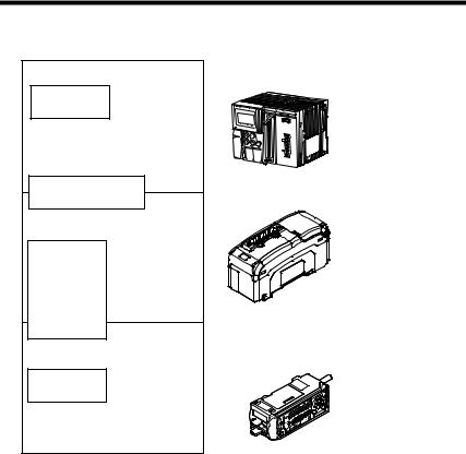
Relevant Manuals
The manuals to relevant to this document are as follows:
Manuals relevant to CPU unit
Example: KV-5000 user's manual
Manuals relevant to
CC-Link master unit
Example: KV-CL20 user's manual
This manual
Manuals of sensor amplifier main unit
Example:
SK-1000 series instruction manual
PLC CPU unit CC-Link master unit
DL-CL1 (This unit)
Sensor amplifier
4- CC-Link Compatible Network Unit DL-CL1 User’s Manual (SK-1000) -

Manual Organization
1 

2

3

4

Before Using
Connection and
Configuration
Communicating with the SK-1000 Series
Specifications
Appendix
This chapter provides an overview of the DL-CL1 and describes its part names and functions.
This chapter explains the procedures for connecting sensor amplifiers to the DL-CL1 and how to configure the data link.
This chapter describes the configuration of the memory linked to the CC-Link master station and provides communication time charts.
This chapter describes the specifications and dimensions of the DL-CL1.
Provides the parameter list, as well as troubleshooting instructions.
1
2
3
4
5
- CC-Link Compatible Network Unit DL-CL1 User’s Manual (SK-1000) - |
5 |

Table of Contents
Safety Precautions............................................................................. |
1 |
General Precautions .......................................................................... |
1 |
Precautions for Use ........................................................................... |
1 |
Notes on Regulations and Standards ................................................ |
2 |
Relevant Manuals............................................................................... |
4 |
Manual Organization.......................................................................... |
5 |
Table of Contents............................................................................... |
6 |
Terms Used in This Document ......................................................... |
8 |
Chapter 1 Before Using
1-1 |
DL-CL1 Overview ............................................................................... |
1-2 |
|
Overview......................................................................................... |
1-2 |
|
Types and Number of Connectable Sensor Amplifiers ................... |
1-2 |
1-2 |
Checking the Package Contents ...................................................... |
1-3 |
|
Package Content ............................................................................ |
1-3 |
|
List of Optional Parts....................................................................... |
1-3 |
1-3 |
Names and Functions of Each Part ................................................. |
1-4 |
Chapter 2 Connection and Configuration
2-1 |
Installation and Connection to Sensor Amplifiers |
......................... 2-2 |
|
ID Number Assignments to Sensor Amplifiers................................ |
2-2 |
|
Installation and Connection to Sensor Amplifiers ........................... |
2-3 |
2-2 |
Wiring.................................................................................................. |
2-6 |
|
Connecting to the CC-Link System................................................. |
2-6 |
2-3 |
Configuring the Data Link............................................................... |
2-10 |
|
Configuring the Master Station ..................................................... |
2-10 |
|
Configuring the DL-CL1 ................................................................ |
2-10 |
Chapter 3 Communicating with the SK-1000 Series
3-1 |
CC-Link Communication and Operating Modes |
............................. 3-2 |
|
Data Exchanged by Cyclic Transfer................................................ |
3-2 |
|
Selecting an Operating Mode of the DL-CL1 .................................. |
3-3 |
3-2 |
Device Maps ....................................................................................... |
3-4 |
|
Device Maps for Small-Memory Mode 1, |
|
|
Small-Memory Mode 2, and Monitor Mode 1.................................. |
3-4 |
|
Device Maps for Monitor Mode 2, Full Mode 1, and Full Mode 2 . 3-13 |
|
3-3 |
Communication Methods................................................................ |
3-21 |
|
Reading an Output from a Sensor Amplifier ................................. |
3-21 |
6- CC-Link Compatible Network Unit DL-CL1 User’s Manual (SK-1000) -
|
Table of Contents |
|
|
|
|
|
Entering an External Input into a Sensor Amplifier ....................... |
3-21 |
|
Reading Judgment Values (P.V. Values) from Sensor Amplifiers 3-22 |
|
|
Changing the BANK Number of Sensor Amplifiers....................... |
3-24 |
|
Issuing a Motion Command to a Sensor Amplifier........................ |
3-25 |
|
Rewriting a Setting Value of a Sensor Amplifier ........................... |
3-26 |
|
Reading/Writing Settings or Status of a Sensor Amplifier............. |
3-26 |
3-4 |
Command Parameter List ............................................................... |
3-29 |
|
Common Command Parameter List ............................................. |
3-29 |
|
Command Parameter List for SK-1000 Series.............................. |
3-31 |
|
|
|
Chapter 4 Specifications |
|
|
|
|
|
4-1 |
Specifications .................................................................................... |
4-2 |
4-2 |
Data Processing Times ..................................................................... |
4-3 |
4-3 |
Dimensions ........................................................................................ |
4-5 |
|
|
|
Chapter 5 Appendix |
|
|
|
|
|
5-1 |
Troubleshooting ................................................................................ |
5-2 |
5-2 |
Index ................................................................................................... |
5-5 |
- CC-Link Compatible Network Unit DL-CL1 User’s Manual (SK-1000) - |
7 |

Terms Used in This Document
This document uses the following terms:
Term |
Description |
|
|
Sensor |
A sensor amplifier. |
|
|
Main unit |
A sensor amplifier that has a power line and can operate alone. |
|
|
Expansion unit |
A sensor amplifier that does not have a power line and must be |
|
connected to a main unit. |
|
The name of KEYENCE's wiring-saving system for sensor amplifi- |
D-bus |
ers. |
|
Supports SK-1000 Series static sensor and others. |
|
|
8- CC-Link Compatible Network Unit DL-CL1 User’s Manual (SK-1000) -
|
|
|
|
Before Using |
1 |
|
|
This chapter provides an overview of the DL-CL1 and describes its |
|
||
|
|
||
part names and functions. |
|
|
|
|
|
|
|
1-1 |
DL-CL1 Overview............................................... |
1-2 |
1-2 |
Checking the Package Contents ........................ |
1-3 |
1-3 |
Names and Functions of Each Part.................... |
1-4 |
- CC-Link Compatible Network Unit DL-CL1 User’s Manual (SK-1000) - |
1-1 |
1
Using Before
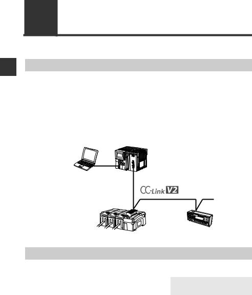
1-1 DL-CL1 Overview
Overview
This unit operates as a remote device station (Ver. 1.1 and 2 switchable) of a CC-Link system. Using CC-Link communications, the sensor amplifiers and other units connected to the DL-CL1 can transmit their ON/OFF control signals and current values as communication data to PLC or other equipment.
The DL-CL1 supports cyclic transfer and extended cyclic transfer, enabling data communication without the need of a ladder program. In addition, remote input/output signals can be used as handshake signals to read/write settings of sensor amplifiers and to execute motion commands on the sensor amplifiers.
System configuration example
PLC or other host device (CC-Link master unit)
DL-CL1 (This unit)
CC-Link slave
D-bus compatible sensor amplifier
Types and Number of Connectable Sensor Amplifiers
Number of Connectable Sensor Amplifiers
Name |
Amplifier form |
Main unit |
Expansion |
Maximum number of |
|
|
|
|
unit |
connectable units |
|
SK-1000 |
DIN rail |
SK-1000 |
SK-1050 |
8 |
|
Series |
mounting type |
(1 main unit, 7 expansion units) |
|||
|
|
||||
|
|
|
|
|
The DL-CL1 can connect multiple sensor amplifiers (a single main unit and multiple expansion units) which support D-Bus. "D-bus" is the name of KEYENCE's wiringsaving system for sensor amplifiers.
Different types of sensor amplifiers with D-bus support can be connected to the single DL-CL1 unit.
How many and what different types of sensor amplifiers can be connected depends on the sensor amplifiers or units to be connected. Please inquire for details.
1-2 |
- CC-Link Compatible Network Unit DL-CL1 User’s Manual (SK-1000) - |
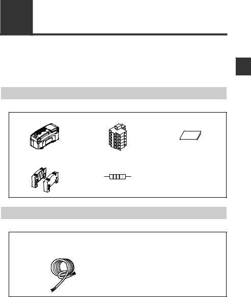
1-2 Checking the Package Contents
Before using the DL-CL1, make sure that the following equipment and accessories are included in the package.
We have thoroughly inspected the package contents before shipment. However, in the event of defective or broken items, contact your nearest KEYENCE office.
Package Content
DL-CL1 main unit x 1 |
CC-Link connector x 1 |
Expansion connector |
|
|
sticker x 1 |
End unit x 2 Resistor Instruction manual x 1  110 1/2W
(brown/brown/brown/gold)
List of Optional Parts
OP-79426 (CC-Link Ver. 1.10 compatible cable, 20 m) OP-79427 (CC-Link Ver. 1.10 compatible cable, 100 m)
Cable x 1
1
Using Before
- CC-Link Compatible Network Unit DL-CL1 User’s Manual (SK-1000) - |
1-3 |

1
Using Before
1-3 Names and Functions of Each Part
This section describes the part names and functions of the DL-CL1.
(1)Transmission rate setting switch
(2)Station number setting switch
|
|
|
|
|
|
|
|
|
|
|
|
|
|
|
|
|
|
(3) Operating mode setting switch |
||
|
|
|
|
|
|
|
|
|
|
|
|
|
|
|
|
|
|
|||
|
|
|
|
|
|
|
|
|
|
|
|
|
|
|
|
|
|
|
|
(4) Power indicator (green) |
|
|
|
|
|
|
|
|
|
|
|
|
|
|
|
|
|
|
|
|
|
|
|
|
|
|
|
|
|
|
|
|
|
|
|
|
|
|
|
|
|
|
|
|
|
|
|
|
|
|
|
|
|
|
|
|
|
|
|
|
|
|
(5) Communication indicator (green) |
|
|
|
CONT.IND |
15JN |
|
|
|
(6) Communication error indicator (red) |
||||||||||||
|
|
|
. |
|
|
|
|
|
|
|
|
|
|
|
|
|
|
|
|
|
|
|
|
|
|
|
|
|
|
|
|
|
|
|
|
|
|
|
|
||
|
|
|
|
|
|
|
|
|
|
|
|
|
|
|
|
|
|
|
||
|
|
|
|
|
|
|
|
|
|
|
|
|
|
|
|
|
|
|
||
|
|
|
.EQ |
|
|
|
|
|
|
|
|
|
|
|
|
|
|
|
|
|
|
|
(7) Sensor communication indicator |
30V-20 |
|
(red/green) |
DC, |
DL |
|
Class2 |
CL1 |
|
|
- |
|
|
|
(8) CC-Link connector |
(9)Sensor amplifier connector 


 (for DIN rail mounting type)


(10)Sensor amplifier connector (for panel mounting type
and large display type)
Name |
|
|
|
|
Description |
|
|
|
|
|
||||
|
|
|
|
|
|
|
|
|
|
|
|
|
||
(1) Transmission rate setting |
Sets the transmission rate of CC-Link. |
|
|
|
||||||||||
switch |
|
|
|
|
|
|
|
|
|
|
|
|
||
|
|
|
|
No. |
|
0 |
1 |
2 |
|
3 |
|
4 |
5 to 9 |
|
|
|
|
|
|
|
|
|
|
|
|
|
|
|
|
|
|
|
|
Transmission rate |
156k |
625k |
2.5M |
|
5M |
|
10M |
Cannot be set |
|
|
|
|
|
|
(bps) |
|
|
|
|||||||
|
|
|
|
|
|
|
|
|
|
|
|
|
|
|
|
|
|
Default value: 0 |
|
|
|
|
|
|
|
|
|||
|
|
|
|
|
|
|
|
|
|
|
|
|||
(2) Station number setting |
Sets the station number of the DL-CL1 in the CC- |
|||||||||||||
switch |
Link. |
|
|
|
|
|
|
|
|
|
|
|||
|
|
|
x10: Ten's digit |
|
|
|
|
|
|
|
|
|
||
|
|
|
x1: One's digit |
|
|
|
|
|
|
|
|
|
||
|
|
|
|
|
|
|
|
|
|
|
|
|
|
|
Setting range: 01 to 64
Default value: 01
1-4 |
- CC-Link Compatible Network Unit DL-CL1 User’s Manual (SK-1000) - |
|
|
|
|
|
|
|
|
|
|
|
1-3 Names and Functions of Each Part |
||||||||||
|
|
|
|
|
|
|
|
|
|
|
|
|
|
|
|
|
|
|
|
|
|
|
|
|
|
|
|
|
|
|
|
|
|
|
|
|
|
|
|
|
|
|
|
|
|
Name |
|
|
|
|
|
|
Description |
|
|
|
|
|
|
||||||
|
|
|
|
|
|
|
|
|
|
|
|
|
|
|
|
|
|
|
|
||
|
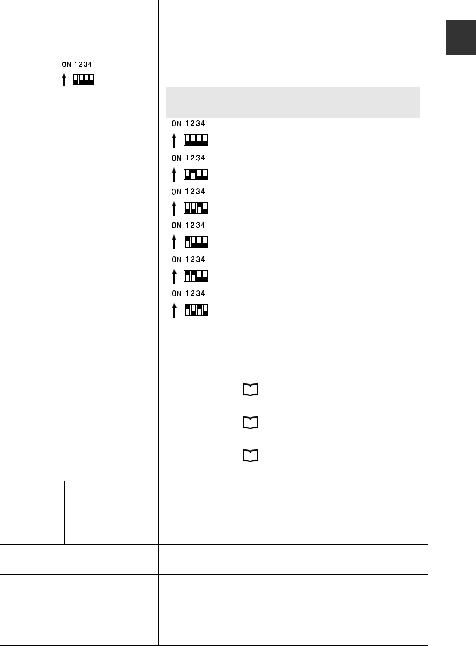
(3) Operating mode setting |
Sets the operating mode of the DL-CL1 in the CC- |
|
||||||||||||||||||
|
switch |
Link. The specific data that can be communicated |
|||||||||||||||||||
|
|
|
|
|
|
|
using cyclic transfer varies with each operating |
||||||||||||||
|
|
|
|
|
|
|
mode. |
|
|
|
|
|
|
|
|
|
|
|
|||
|
|
|
|
|
|
|
|
|
|
|
|
|
|
|
|
|
|
||||
|
|
|
|
|
|
|
|
|
|
|
|
|
|
|
|
|
|
|
|
|
|
|
|
|
|
|
|
|
|
Switchsetting |
Operating mode |
Station |
|
Number of link points |
|
||||||||
|
|
|
|
|
|
|
|
configuration |
|
RX/RY |
RWw/RWr |
|
|
||||||||
|
|
|
|
|
|
|
|
|
|
|
|
|
|
|
|
|
|||||
|
|
|
|
|
|
|
|
|
|
|
|
|
|
|
|
|
|||||
|
|
|
|
|
|
|
|
|
|
|
Small-memory mode 1 |
1-station, 1x |
|
32 |
|
4 |
|
|
|||
|
|
|
|
|
|
|
|
|
|
|
(1-output, 1-input) |
|
|
|
|
|
|
|
|
||
|
|
|
|
|
|
|
|
|
|
|
|
|
|
|
|
|
|
|
|
|
|
|
|
|
|
|
|
|
|
|
|
|
Small-memory mode 2 |
2-station, 1x |
|
64 |
|
8 |
|
|
|||
|
|
|
|
|
|
|
|
|
|
|
|
|
|
|
|||||||
|
|
|
|
|
|
|
|
|
|
|
(3-output, 3-input) |
|
|
|
|
|
|
|
|
||
|
|
|
|
|
|
|
|
|
|
|
|
|
|
|
|
|
|
|
|
|
|
|
|
|
|
|
|
|
|
|
|
|
Monitor mode 1 |
|
|
|
|
|
|
|
|
||
|
|
|
|
|
|
|
|
|
|
|
(5-output, 5-input, current value, |
4-station, 1x |
|
128 |
|
16 |
|
|
|||
|
|
|
|
|
|
|
|
|
|
|
|
|
|
|
|||||||
|
|
|
|
|
|
|
|
|
|
|
|
BANK change) |
|
|
|
|
|
|
|
|
|
|
|
|
|
|
|
|
|
|
|
|
|
|
|
|
|
|
|
|
|
|
|
|
|
|
|
|
|
|
|
|
|
|
Monitor mode 2 |
|
|
|
|
|
|
|
|
||
|
|
|
|
|
|
|
|
|
|
|
(5-output, 5-input, current value, |
1-station, 8x |
|
128 |
|
32 |
|
|
|||
|
|
|
|
|
|
|
|
|
|
|
|
|
|
|
|||||||
|
|
|
|
|
|
|
|
|
|
|
|
BANK change) |
|
|
|
|
|
|
|
|
|
|
|
|
|
|
|
|
|
|
|
|
|
|
|
|
|
|
|
|
|
|
|
|
|
|
|
|
|
|
|
|
|
|
|
Full mode 1 |
4-station, 2x |
|
224 |
|
|
|
|
|
|
|
|
|
|
|
|
|
|
|
|
|
(5-output, 5-input, current value, |
|
|
32 |
|
|
|||||
|
|
|
|
|
|
|
|
|
|
|
BANK change, setting value change) |
|
|
|
|
|
|
|
|
||
|
|
|
|
|
|
|
|
|
|
|
|
|
|
|
|
|
|
|
|
|
|
|
|
|
|
|
|
|
|
|
|
|
|
Full mode 2 |
|
|
|
|
|
|
|
|
|
|
|
|
|
|
|
|
|
|
|
|
(5-output, 5-input, current value, |
2-station, 8x |
|
384 |
|
64 |
|
|
|||
|
|
|
|
|
|
|
|
|
|
|
|
|
|
|
|||||||
|
|
|
|
|
|
|
|
|
|
|
BANK change, setting value change) |
|
|
|
|
|
|
|
|
||
|
|
|
|
|
|
|
|
|
|
|
|
|
|
|
|
|
|
|
|
|
|
|
|
|
|
|
|
|
|
Others |
Cannot be set |
|
|
|
|
|
|
|
|
||||
|
|
|
|
|
|
|
|
|
|
|
|
|
|
|
|||||||
|
|
|
|
|
|
|
Default value: Small-memory mode 1 |
|
|
|
|
|
|
||||||||
|
|
|
|
|
|
|
|
|
|
|
|
|
|
|
|
|
|
|
|
|
|
|
(4) Power indicator |
When normal: Lit in green |
|
|
|
|
|
|
|
|
|||||||||||
|
|
|
|
|
|
|
|
|
|
|
|
|
|
|
|
|
|
|
|
||
|
(5) Communication indicator |
For details, see |
|
"Troubleshooting" (page 5-2). |
|||||||||||||||||
|
|
||||||||||||||||||||
|
|
|
|
|
|
|
|
|
|
|
|
|
|
|
|
|
|
|
|
|
|
|
(6) Communication error |
When normal: Not lit |
|
|
|
|
|
|
|
|
|||||||||||
|
indicator |
For details, see |
|
"Troubleshooting" (page 5-2). |
|||||||||||||||||
|
|
||||||||||||||||||||
|
|
|
|
|
|
|
|
|
|
|
|
|
|
|
|
|
|
|
|
|
|
|
(7) Sensor communication |
When normal: Lit in green |
|
|
|
|
|
|
|
|
|||||||||||
|
indicator |
For details, see |
|
"Troubleshooting" (page 5-2). |
|||||||||||||||||
|
|
||||||||||||||||||||
|
|
|
|
|
|
|
|
|
|
|
|
|
|
|
|
|
|
|
|
|
|
|
(8) CC-Link connector |
Attach the CC-Link cable to this connector. |
|
|
|
|
|||||||||||||||
|
|
|
|
|
|
|
|
|
|
|
|
|
|
|
|
|
|
|
|
|
|
|
|
|
DA/DB/DG |
Communication signal |
|
|
|
|
|
|
|
|
|||||||||
|
|
|
|
|
|
|
|
|
|
|
|
|
|
|
|
|
|
|
|
||
|
|
|
SLD |
Connect the shielded wire of the CC-Link cable. |
|||||||||||||||||
|
|
|
|
|
|
|
|
|
|
|
|
|
|
|
|
|
|
|
|
||
|
|
|
FG |
Ground this functional ground terminal according to |
|||||||||||||||||
a Class D (Class 3) grounding.
(9)Sensor amplifier connecAttach the sensor amplifier to this connector. tor (for DIN rail mounting)
(10)Sensor amplifier |
Attach the sensor amplifier to this connector. |
connector |
When shipped from the factory, a protective sticker |
(for panel mounting/large |
is installed. |
display) |
The optional expansion cable (OP-35361) is used |
|
for this connection. |
1
Using Before
- CC-Link Compatible Network Unit DL-CL1 User’s Manual (SK-1000) - |
1-5 |

1-3 Names and Functions of Each Part
MEMO
1
Using Before
1-6 |
- CC-Link Compatible Network Unit DL-CL1 User’s Manual (SK-1000) - |
|
|
|
|
|
Connection and Configuration |
2 |
|
||
This chapter explains the procedures for connecting |
sensor |
|
||
|
|
|||
amplifiers to the DL-CL1 and how to configure the data link. |
|
|
|
|
|
|
|
|
|
2-1 |
Installation and Connection to Sensor Amplifiers |
|
|
........................................................................... |
2-2 |
2-2 |
Wiring ................................................................. |
2-6 |
2-3 |
Configuring the Data Link................................. |
2-10 |
- CC-Link Compatible Network Unit DL-CL1 User’s Manual (SK-1000) - |
2-1 |
2
rationuConfig and Connection
2-1 Installation and Connection to Sensor Amplifiers
This section provides the procedures for installing the DL-CL1 and connecting to sensor amplifiers.
The DL-CL1 can be connected with the expansion units of sensor amplifiers which support D-bus. ("D-bus" is the name of KEYENCE's wiring-saving system for sensor amplifiers.) How many sensor amplifiers can be connected depends on the sensor amplifiers or units to be connected. For specific numbers of connections, refer to the manual of each sensor amplifier.
ID Number Assignments to Sensor Amplifiers
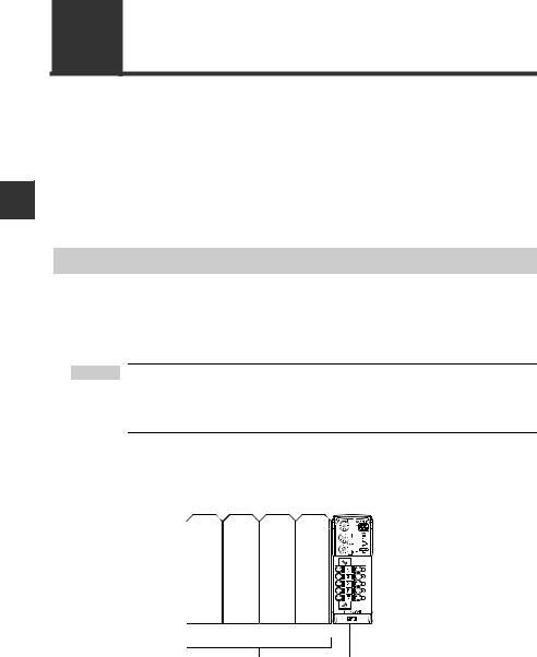
When connecting the DL-CL1 to a sensor amplifier which can be configured with expansion units, the main unit will be assigned ID number 01, with the expansion units assigned ID numbers of 02 to 08.
 Point • The ID number assignments to sensor amplifiers cannot be changed by the user.
•In this manual, ID number 01 to ID number 08 are denoted as ID 01 to ID 08, respectively.
For DIN rail mounting type
ID number 01 |
02 |
... |
08 |
Main unit Expansion unit Expansion unit Expansion unit
Sensor amplifier DL-CL1
2-2 |
- CC-Link Compatible Network Unit DL-CL1 User’s Manual (SK-1000) - |
2-1 Installation and Connection to Sensor Amplifiers
Installation and Connection to Sensor Amplifiers
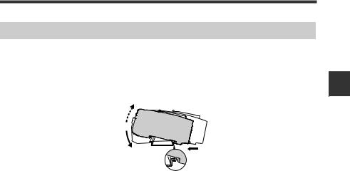
Mounting on a DIN rail
1 |
Align the claw on the bottom of the amplifier with the DIN rail. While push- |
ing the amplifier in the direction of arrow (1), press down in the direction |
|
|
of arrow (2). |
|
(3) |
|
(2) |
|
(1) |
2 |
To remove the DL-CL1, raise the main unit in the direction of arrow (3) |
while pushing it the direction of arrow (1). |
2
rationuConfig and Connection
- CC-Link Compatible Network Unit DL-CL1 User’s Manual (SK-1000) - |
2-3 |
2
rationuConfig and Connection
2-1 Installation and Connection to Sensor Amplifiers
Procedures for connecting to sensor amplifiers
The CC-Link compatible communication unit DL-CL1 must be connected to sensor amplifiers before it can provide its function.
The connecting procedure varies with the mounting type of the sensor amplifiers to be connected.
Make sure that the power to the sensor amplifier is off before starting to NOTICE connect the CC-Link compatible communication unit DL-CL1. Perform-
ing the procedure with the power on may damage the DL-CL1.
 Point For the instructions on connecting additional sensor amplifiers, refer to the instruction manual of the sensors amplifiers.
Connecting to sensor amplifiers of DIN rail mounting type
1 |
Remove the expansion protective cover from the sensor amplifier to be |
connected. |
Sensor amplifier
Expansion protective cover
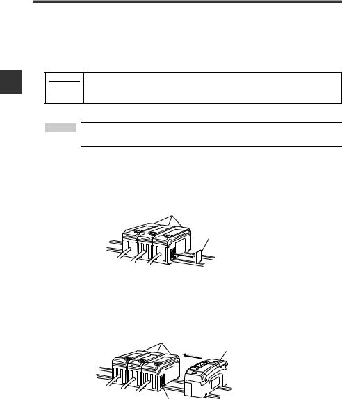
2 |
Install the CC-Link compatible communication unit DL-CL1 on the DIN rail |
and connect to the sensor amplifier. |
|
|
Ensure a tight connection, leaving no space between the CC-Link compatible |
|
communication unit DL-CL1 and the sensor amplifier. |
Sensor amplifier |
CC-Link compatible |
|
|
|
communication unit DL-CL1 |
Connector
2-4 |
- CC-Link Compatible Network Unit DL-CL1 User’s Manual (SK-1000) - |
2-1 Installation and Connection to Sensor Amplifiers
Make sure that the sensor amplifier connector (for DIN rail mounting type) is not askew on the side face of the CC-Link compatible communication unit DL-CL1, as shown below. If the connector is askew, the DLCL1 may become damaged when connected to the sensor amplifier.
Sensor amplifier connector
NOTICE
|
CC-Link compatible |
|
communication unit DL-CL1 |
|
|
3 |
Mount the supplied end units (OP-26751: a set of two pieces) on the outer |
side faces of the amplifier and the CC-Link compatible communication |
unit DL-CL1. Then, fix the end units with the screws on the top of each end unit (2 points x 2 units). (Tightening torque: 0.6 N•m or less)
Mount the end units in the same way as the CC-Link compatible communication unit DL-CL1.
End unit
End unit
2
rationuConfig and Connection
Press the CC-Link compatible communication unit DL-CL1 into full engagement with the sensor amplifier. If the DL-CL1 is connected in
NOTICE
slant position or not pressed fully, it may be damaged when the power is turned on.
- CC-Link Compatible Network Unit DL-CL1 User’s Manual (SK-1000) - |
2-5 |

2
rationuConfig and Connection
2-2 Wiring
This section describes how to wire the DL-CL1.
 Point • Turn off the power before starting the cabling operation.
•For more information about the CC-Link system, including cable length and cabling methods, refer to the document of the CC-Link master unit.
Connecting to the CC-Link System
Use the following procedures to connect the DL-CL1 to the CC-Link system.
Usable cables
For connection between the DL-CL1 and the CC-Link system, use CC-Link cables (Ver. 1.10 or later) accredited by the CC-Link Partner Association.
CC-Link cables (for Ver. 1.10) are available as optional items.
OP-79426 (20 m) OP-79427 (100 m)
 Point To ensure normal communication, only use the CC-Link cables.
Trimming the cable
1 Strip the cable sheath.
Strip approximately 50 mm of the sheath from the end of the CC-Link cable, with care to avoid damaging the shield braid of the cable.
Sheath |
|
Approx. 50 |
|
mm |
|||
|
|
||||||
|
|
|
|
|
|
|
|
|
|
|
|
|
|
|
|
|
|
|
|
|
|
|
|
Shield braid
2-6 |
- CC-Link Compatible Network Unit DL-CL1 User’s Manual (SK-1000) - |
2-2 Wiring
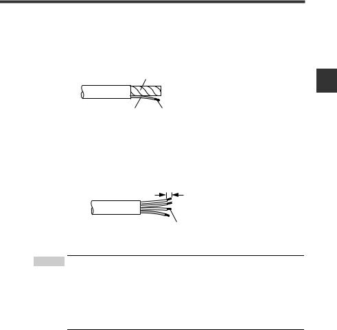
2 Trim the shield.
Upbraid the shield braid carefully. Find the bare drain wire (twisted or flying) inside the shield braid. Twist together the unbranded shield braid and the drain wire securely, and then put on the insulating tube.
Aluminum polyester laminated tape
Insulating tube |
Shield braid twisted together |
3 Strip the sheathed conductors.
Strip approximately 10 mm of sheath from each signal wire, by removing the aluminum polyester laminated tape. Take care not to damage the signal wires. Twist together the exposed conductors securely.
Approx. 10 mm
Twist together the conductors
 Point • If you are using solderless terminals, perform cable wiring/ trimming appropriately to suit the specifications of the particular terminals.
Recommended solderless terminals: Phoenix Contact's A/AI Series
•Do not perform soldering (pre-soldering) on the trimmed end of the cable.
2
rationuConfig and Connection
- CC-Link Compatible Network Unit DL-CL1 User’s Manual (SK-1000) - |
2-7 |
2
rationuConfig and Connection
2-2 Wiring
Connecting the cable
Use the following procedures to connect to the CC-Link connector supplied with the DL-CL1.
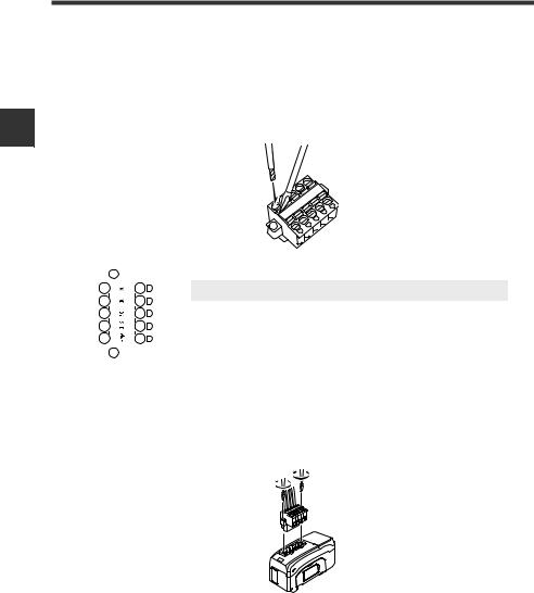
1 Connect the trimmed cable to the CC-Link connector.
Insert the cable completely.
|
|
|
|
|
|
|
|
|
|
|
|
|
|
|
|
|
|
|
|
|
|
|
|
|
|
|
|
|
|
|
Terminal name |
Function |
|
|
|
|
|
|
|
|
|
|
|
|
|
|
|
|
|
|
|
|
DA/DB/DG |
Communication signal |
|
|
|
|
|
|
|
|
|
||
|
|
|
|
|
|
|
|
|
|
|
|
|
|
|
|
|
|
|
|
SLD |
Connect the shielded wire of the CC-Link cable. |
|
|
|
|
|
|
|
|
|
||
|
|
|
|
|
|
|
|
|
|
|
|
|
|
|
|
|
|
|
|
FG |
Ground this functional ground terminal according to Class D (Class 3) grounding |
|
|
|
|
|
|
|
|
|
||
|
|
|
|
|
|
|
|
|
||
|
|
|
|
|
|
|
|
|
|
|
2 Attach the CC-Link connector to the DL-CL1.
Plug the connector into the DL-CL1 and screw it down with the screws on each end.
(Tightening torque: 0.2 to 0.3 N•m)
2-8 |
- CC-Link Compatible Network Unit DL-CL1 User’s Manual (SK-1000) - |
Loading...