

Page 1
406GB
DL-CL1
User’s Manual
(SK-1000)
Read this manual before using the product in order to
achieve maximum performance.
Keep this manual in a safe place for future reference.
CC-Link Compatible Network Unit
Page 2
Introduction
This manual describes the basic operations and hardware functions of the DL-CL1. Read
the manual carefully to ensure safe performance and function of the DL-CL1.
Keep this manual in a safe place for future reference.
Ensure that the end user of this product receives this manual.
Symbols
The following symbols alert you to matters concerning the prevention of injury and product
damage.
It indicates cautions and limitations that must be followed during operation.
It indicates additional information on proper operation.
It indicates tips for better understanding or useful information.
The names of systems and products used in this manual are the trademarks or registered
trademarks of their respective owners.
It indicates a hazardous situation which, if not avoided, will result in
death or serious injury.
It indicates a hazardous situation which, if not avoided, could result
in death or serious injury.
It indicates a hazardous situation which, if not avoided, could result
in minor or moderate injury.
It indicates a situation which, if not avoided, could result in product
damage as well as property damage.
Point
Important
CAUTION
DANGER
NOTICE
WARNING
Reference
Page 3
Safety Precautions
CAUTION
NOTICE
General Precautions
• Before and while operating this product, confirm that it provides its functions
and performance correctly.
• Implement sufficient safety measures to prevent human and physical damages
in case this product fails.
• Be aware that the product functions and performance are not warranted if the
product is used outside the range of stated specifications or is modified by the
customer.
• Combining this product with other equipment requires sufficient consideration
because the proper functions and performance may not be provided depending
on the environment.
• Do not use this product in applications for human protection.
• Do not expose equipment, including peripherals, to rapid temperature changes.
Equipment failure may result from dew condensation.
Precautions for Use
• In the following cases, immediately turn off the power. Leaving
the equipment in unusual condition in may result in human
injury or equipment failure.
- Water or foreign matter entered the main unit;
- The case is broken, for example if it is dropped;
- Smoke or unusual smell comes out of the product.
• Use the correct power voltage. Failure to observe may result in
injury or failure.
• Do not disassembly or modify this product. Failure to observe
may result in injury.
Do not turn off the power while you are setting any item. Doing this
may cause loss of data settings wholly or partially.
406GB
1
Page 4

Equipment Environment
For safe, trouble-free operation of this product, the product must not be installed on
the following locations:
• Humid, dusty, or ill-ventilated.
• Exposed to direct sunlight or heating source.
• Exposed to corrosive or flammable gases.
• Exposed directly to vibration or shock.
• Exposed to water, oil, or chemical splashes.
• Exposed to static electricity.
Noise Protection
If this product is installed on a location near a noise source, e.g., power source or
high-voltage line, it may malfunction or fail because of noise. Use protection measures, such as using a noise filter or running the cords separately.
About Power Supply
• Noise superimposed on the power supply could cause malfunction. Use a stabi-
lized DC power supply configured with an isolation transformer.
• When using a commercially available switching regulator, be sure to ground the
frame ground terminal or ground terminal.
Notes on Regulations and Standards
UL Certificate
This product is an UL/C-UL Listed product.
• UL File No. E207185
• Category NRAQ, NRAQ7
Be sure to consider the following specifications when using this product as an UL/CUL Listed Product.
• Use a power supply with Class 2 output defined in NFPA70 (NEC: National Electrical Code).
• For wiring to the CC-Link connector, use the AWG 12-24 copper wire with temperature rating 60
• Use this product under pollution degree 2
• This product is an open type device. Therefore, it must be installed in an enclosure
with IP 54 or higher. (e.g. Industrial control panel)
2
- CC-Link Compatible Network Unit DL-CL1 User’s Manual (SK-1000) -
C or more.
Page 5

CE Marking
Keyence Corporation has confirmed that this product complies with the essential
requirements of the applicable EC Directive, based on the following specifications.
Be sure to consider the following specifications when using this product in the Member State of European Union.
■ EMC Directive
EMI : EN55011, Class A
EMS : EN61000-6-2
• Install this product in a conductive enclosure. (e.g. Industrial control panel)
Remarks
These specifications do not give any guarantee that the end-product with this
product incorporated complies with the essential requirements of EMC Directive.
The manufacturer of the end-product is solely responsible for the compliance on
the end-product itself according to EMC Directive.
- CC-Link Compatible Network Unit DL-CL1 User’s Manual (SK-1000) -
3
Page 6
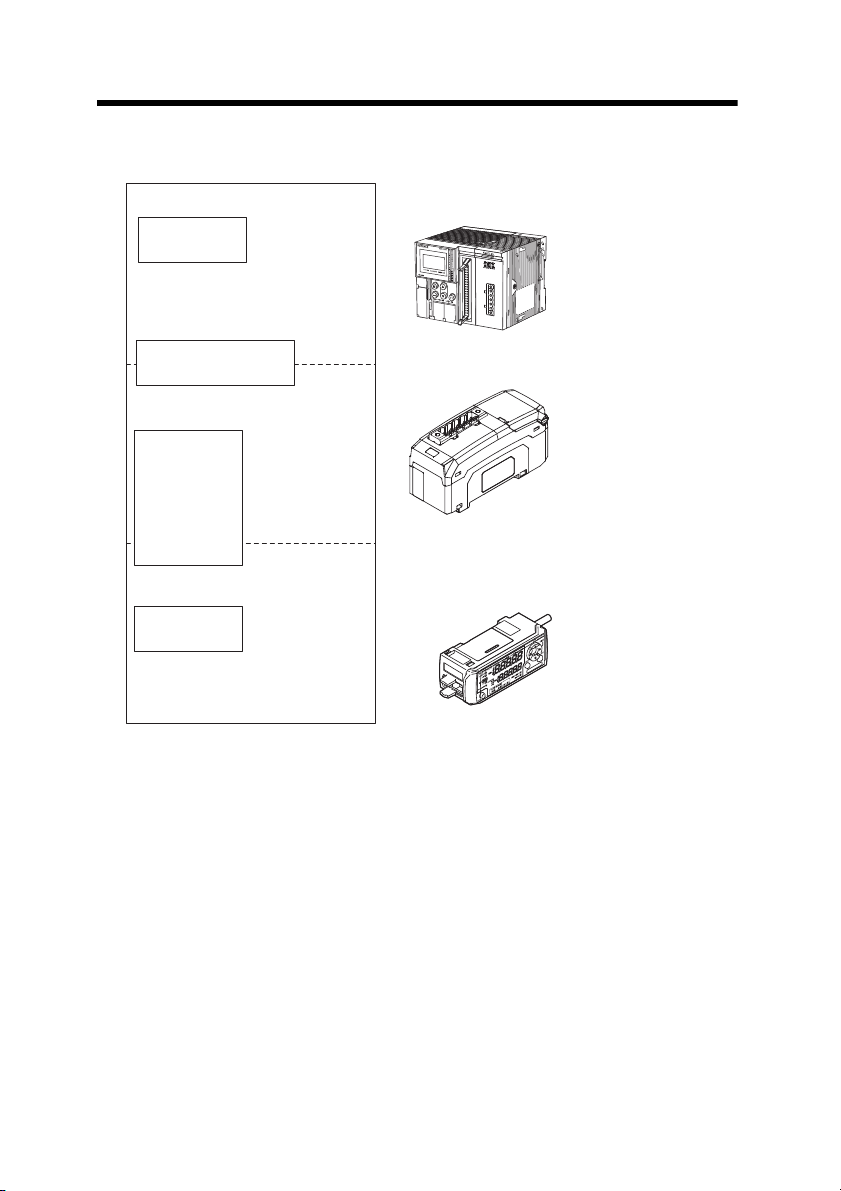
Relevant Manuals
Sensor amplifier
Manuals relevant
to CPU unit
Manuals relevant to
CC-Link master unit
Manuals of sensor
amplifier main unit
PLC CPU unit
CC-Link master unit
DL-CL1 (This unit)
This manual
Example:
・
SK-1000 series instruction manual
Example: KV-5000 user's manual
Example: KV-CL20 user's manual
The manuals to relevant to this document are as follows:
4
- CC-Link Compatible Network Unit DL-CL1 User’s Manual (SK-1000) -
Page 7

Manual Organization
This chapter provides an overview of the DL-CL1
and describes its part names and functions.
Before Using
1
This chapter explains the procedures for
connecting sensor amplifiers to the DL-CL1
and how to configure the data link.
Connection and
Configuration
2
This chapter describes the configuration of the
memory linked to the CC-Link master station and
provides communication time charts.
Communicating with
the SK-1000 Series
3
Provides the parameter list, as well as
troubleshooting instructions.
Appendix
5
This chapter describes the specifications
and dimensions of the DL-CL1.
Specifications
4
1
2
3
4
5
- CC-Link Compatible Network Unit DL-CL1 User’s Manual (SK-1000) -
5
Page 8

Table of Contents
Safety Precautions.............................................................................1
General Precautions .......................................................................... 1
Precautions for Use ........................................................................... 1
Notes on Regulations and Standards ................................................ 2
Relevant Manuals...............................................................................4
Manual Organization..........................................................................5
Table of Contents...............................................................................6
Terms Used in This Document .........................................................8
Chapter 1 Before Using
1-1 DL-CL1 Overview ............................................................................... 1-2
Overview ......................................................................................... 1-2
Types and Number of Connectable Sensor Amplifiers ................... 1-2
1-2 Checking the Package Contents...................................................... 1-3
Package Content ............................................................................ 1-3
List of Optional Parts....................................................................... 1-3
1-3 Names and Functions of Each Part ................................................. 1-4
Chapter 2 Connection and Configuration
2-1 Installation and Connection to Sensor Amplifiers ......................... 2-2
ID Number Assignments to Sensor Amplifiers................................ 2-2
Installation and Connection to Sensor Amplifiers ........................... 2-3
2-2 Wiring.................................................................................................. 2-6
Connecting to the CC-Link System ................................................. 2-6
2-3 Configuring the Data Link............................................................... 2-10
Configuring the Master Station ..................................................... 2-10
Configuring the DL-CL1 ................................................................ 2-10
Chapter 3
3-1 CC-Link Communication and Operating Modes............................. 3-2
3-2 Device Maps ....................................................................................... 3-4
3-3 Communication Methods ................................................................ 3-21
6
- CC-Link Compatible Network Unit DL-CL1 User’s Manual (SK-1000) -
Communicating with the SK-1000 Series
Data Exchanged by Cyclic Transfer................................................ 3-2
Selecting an Operating Mode of the DL-CL1 .................................. 3-3
Device Maps for Small-Memory Mode 1,
Small-Memory Mode 2, and Monitor Mode 1.................................. 3-4
Device Maps for Monitor Mode 2, Full Mode 1, and Full Mode 2 . 3-13
Reading an Output from a Sensor Amplifier ................................. 3-21
Page 9

Table of Contents
Entering an External Input into a Sensor Amplifier ....................... 3-21
Reading Judgment Values (P.V. Values) from Sensor Amplifiers 3-22
Changing the BANK Number of Sensor Amplifiers ....................... 3-24
Issuing a Motion Command to a Sensor Amplifier........................ 3-25
Rewriting a Setting Value of a Sensor Amplifier ........................... 3-26
Reading/Writing Settings or Status of a Sensor Amplifier............. 3-26
3-4 Command Parameter List ............................................................... 3-29
Common Command Parameter List ............................................. 3-29
Command Parameter List for SK-1000 Series.............................. 3-31
Chapter 4 Specifications
4-1 Specifications .................................................................................... 4-2
4-2 Data Processing Times ..................................................................... 4-3
4-3 Dimensions ........................................................................................ 4-5
Chapter 5 Appendix
5-1 Troubleshooting ................................................................................ 5-2
5-2 Index ................................................................................................... 5-5
- CC-Link Compatible Network Unit DL-CL1 User’s Manual (SK-1000) -
7
Page 10

Terms Used in This Document
This document uses the following terms:
Term Description
Sensor A sensor amplifier.
Main unit A sensor amplifier that has a power line and can operate alone.
Expansion unit
D-bus
A sensor amplifier that does not have a power line and must be
connected to a main unit.
The name of KEYENCE's wiring-saving system for sensor amplifiers.
Supports SK-1000 Series static sensor and others.
8
- CC-Link Compatible Network Unit DL-CL1 User’s Manual (SK-1000) -
Page 11

Before Using
This chapter provides an overview of the DL-CL1 and describes its
part names and functions.
1-1 DL-CL1 Overview ............................................... 1-2
1-2 Checking the Package Contents........................1-3
1-3 Names and Functions of Each Part.................... 1-4
1
- CC-Link Compatible Network Unit DL-CL1 User’s Manual (SK-1000) -
1-1
Page 12
1-1
PLC or other host device
(CC-Link master unit)
DL-CL1 (This unit)
D-bus compatible sensor amplifier
CC-Link slave
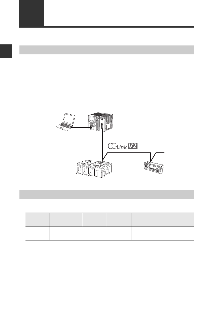
DL-CL1 Overview
1
Overview
Before Using
This unit operates as a remote device station (Ver. 1.1 and 2 switchable) of a CC-Link
system. Using CC-Link communications, the sensor amplifiers and other units connected to the DL-CL1 can transmit their ON/OFF control signals and current values as
communication data to PLC or other equipment.
The DL-CL1 supports cyclic transfer and extended cyclic transfer, enabling data communication without the need of a ladder program. In addition, remote input/output signals can be used as handshake signals to read/write settings of sensor amplifiers and
to execute motion commands on the sensor amplifiers.
System configuration example
Types and Number of Connectable Sensor Amplifiers
Number of Connectable Sensor Amplifiers
Name Amplifier form Main unit
SK-1000
Series
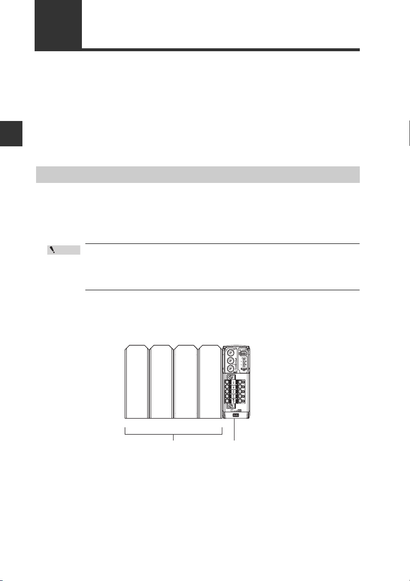
The DL-CL1 can connect multiple sensor amplifiers (a single main unit and multiple
expansion units) which support D-Bus. "D-bus" is the name of KEYENCE's wiringsaving system for sensor amplifiers.
Different types of sensor amplifiers with D-bus support can be connected to the single
DL-CL1 unit.
How many and what different types of sensor amplifiers can be connected depends
the sen
on
1-2
DIN rail
mounting type
sor amplifiers or units to be connected. Please inquire for details.
- CC-Link Compatible Network Unit DL-CL1 User’s Manual (SK-1000) -
SK-1000 SK-1050
Expansion
unit
Maximum number of
connectable units
8
(1 main unit, 7 expansion units)
Page 13
1-2
(brown/brown/brown/gold)
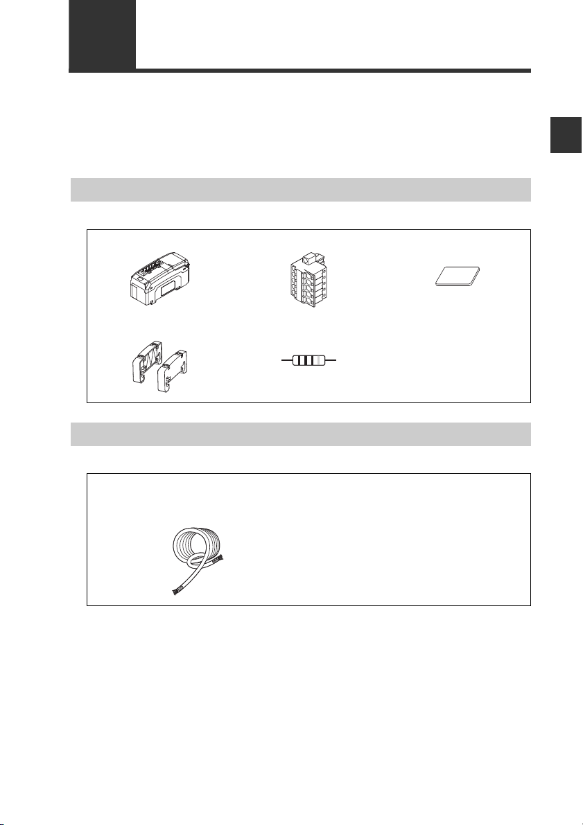
Before using the DL-CL1, make sure that the following equipment and accessories
are included in the package.
We have thoroughly inspected the package contents before shipment. However, in
the event of defective or broken items, contact your nearest KEYENCE office.
Checking the Package Contents
Package Content
DL-CL1 main unit x 1 CC-Link connector x 1 Expansion connector
sticker x 1
1
Before Using
End unit x 2 Resistor
110 1/2W
List of Optional Parts
OP-79426 (CC-Link Ver. 1.10 compatible cable, 20 m)
OP-79427 (CC-Link Ver. 1.10 compatible cable, 100 m)
Cable x 1
Instruction manual x 1
- CC-Link Compatible Network Unit DL-CL1 User’s Manual (SK-1000) -
1-3
Page 14
1
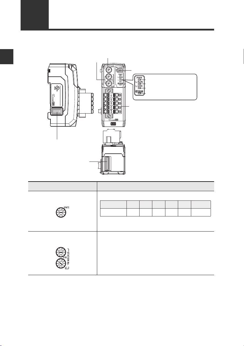
(5)
Communication indicator (green)
(6) Communication error indicator (red)
(7) Sensor communication indicator
(red/green)
(4) Power indicator (green)
(9) Sensor amplifier connector
(for DIN rail mounting type)
(8) CC-Link connector
(1) Transmission rate setting switch
(3) Operating mode setting switch
(2) Station number setting switch
(10) Sensor amplifier connector
(for panel mounting type
and large display type)
DL
CL1
20-30V DC, Class2
15JN
IND.CONT.EQ.
1-3
Names and Functions of Each Part
This section describes the part names and functions of the DL-CL1.
Before Using
Name Description
(1) Transmission rate setting
switch
Sets the transmission rate of CC-Link.
No.
Transmission rate
(bps)
0 1 2 3 4 5 to 9
156k 625k 2.5M 5M 10M
Cannot be set
(2) Station number setting
switch
1-4
Default value: 0
Sets the station number of the DL-CL1 in the CC-
Link.
x10: Ten's digit
x1: One's digit
Setting range: 01 to 64
Default value: 01
- CC-Link Compatible Network Unit DL-CL1 User’s Manual (SK-1000) -
Page 15
Name Description
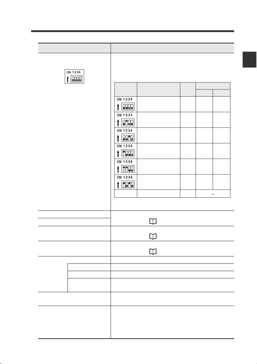
(3) Operating mode setting
switch
1-3 Names and Functions of Each Part
Sets the operating mode of the DL-CL1 in the CCLink. The specific data that can be communicated
using cyclic transfer varies with each operating
mode.
Number of link points
Switch setting
Operating mode
Small-memory mode 1
(1-output, 1-input)
Station
configuration
1-station, 1x
RX/R Y
32
RW w/ RW r
4
1
Before Using
Small-memory mode 2
(3-output, 3-input)
Monitor mode 1
(5-output, 5-input, current value,
BANK change)
Monitor mode 2
(5-output, 5-input, current value,
BANK change)
Full mode 1
(5-output, 5-input, current value,
BANK change, setting value change)
Full mode 2
(5-output, 5-input, current value,
BANK change, setting value change)
Others Cannot be set −
2-station, 1x
4-station, 1x
1-station, 8x
4-station, 2x
2-station, 8x
64
128
128
224
384
Default value: Small-memory mode 1
(4) Power indicator When normal: Lit in green
(5) Communication indicator
(6) Communication error
indicator
(7) Sensor communication
indicator
For details, see "Troubleshooting" (page 5-2).
When normal: Not lit
For details, see "Troubleshooting" (page 5-2).
When normal: Lit in green
For details, see "Troubleshooting" (page 5-2).
(8) CC-Link connector Attach the CC-Link cable to this connector.
DA/DB/DG Communication signal
SLD Connect the shielded wire of the CC-Link cable.
FG Ground this functional ground terminal according to
a Class D (Class 3) grounding.
(9) Sensor amplifier connec-
Attach the sensor amplifier to this connector.
tor (for DIN rail mounting)
(10)Sensor amplifier
connector
(for panel mounting/large
display)
Attach the sensor amplifier to this connector.
When shipped from the factory, a protective sticker
is installed.
The optional expansion cable (OP-35361) is used
for this connection.
8
16
32
32
64
- CC-Link Compatible Network Unit DL-CL1 User’s Manual (SK-1000) -
1-5
Page 16

1
1-3 Names and Functions of Each Part
MEMO
Before Using
1-6
- CC-Link Compatible Network Unit DL-CL1 User’s Manual (SK-1000) -
Page 17

Connection and Configuration
This chapter explains the procedures for connecting sensor
amplifiers to the DL-CL1 and how to configure the data link.
2-1 Installation and Connection to Sensor Amplifiers
........................................................................... 2-2
2-2 Wiring ................................................................. 2-6
2-3 Configuring the Data Link................................. 2-10
2
- CC-Link Compatible Network Unit DL-CL1 User’s Manual (SK-1000) -
2-1
Page 18
2
Point
Connection and Configuration
2-1
This section provides the procedures for installing the DL-CL1 and connecting to
sensor amplifiers.
The DL-CL1 can be connected with the expansion units of sensor amplifiers which
support D-bus. ("D-bus" is the name of KEYENCE's wiring-saving system for sensor
amplifiers.) How many sensor amplifiers can be connected depends on the sensor
amplifiers or units to be connected. For specific numbers of connections, refer to the
manual of each sensor amplifier.
Installation and Connection to Sensor Amplifiers
ID Number Assignments to Sensor Amplifiers
When connecting the DL-CL1 to a sensor amplifier which can be configured with
expansion units, the main unit will be assigned ID number 01, with the expansion
units assigned ID numbers of 02 to 08.
• The ID number assignments to sensor amplifiers cannot be
changed by the user.
• In this manual, ID number 01 to ID number 08 are denoted as ID 01
to ID 08, respectively.
For DIN rail mounting type
2-2
ID number
- CC-Link Compatible Network Unit DL-CL1 User’s Manual (SK-1000) -
01
Main unit
Expansion unit Expansion unit Expansion unit
Sensor amplifier DL-CL1
02
...
08
Page 19

2-1 Installation and Connection to Sensor Amplifiers
(1)
(2)
(3)
Installation and Connection to Sensor Amplifiers
Mounting on a DIN rail
Align the claw on the bottom of the amplifier with the DIN rail. While push-
1
ing the amplifier in the direction of arrow (1), press down in the direction
of arrow (2).
To remove the DL-CL1, raise the main unit in the direction of arrow (3)
2
while pushing it the direction of arrow (1).
2
Connection and Configuration
- CC-Link Compatible Network Unit DL-CL1 User’s Manual (SK-1000) -
2-3
Page 20
2
NOTICE
Point
Sensor amplifier
Expansion protective cover
Sensor amplifier
CC-Link compatible
communication unit DL-CL1
Connector
Connection and Configuration
2-1 Installation and Connection to Sensor Amplifiers
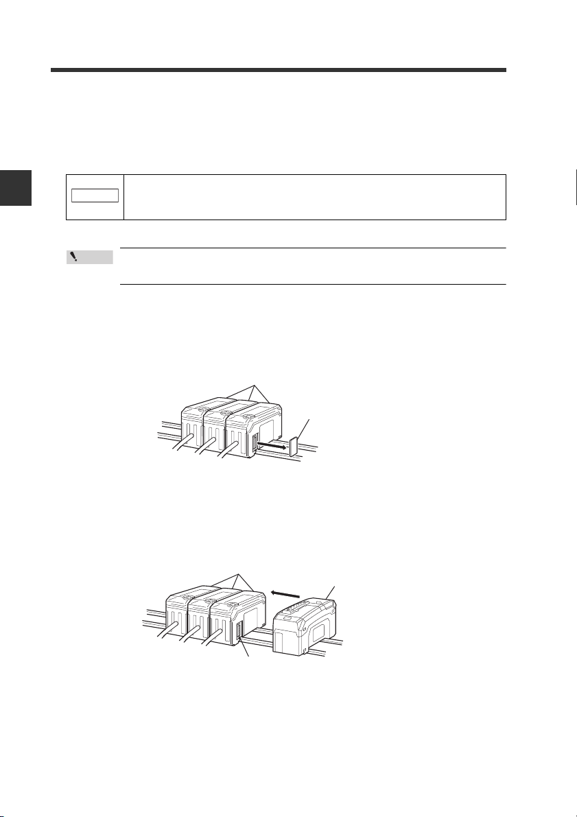
Procedures for connecting to sensor amplifiers
The CC-Link compatible communication unit DL-CL1 must be connected to sensor
amplifiers before it can provide its function.
The connecting procedure varies with the mounting type of the sensor amplifiers to be
connected.
Make sure that the power to the sensor amplifier is off before starting to
connect the CC-Link compatible communication unit DL-CL1. Performing the procedure with the power on may damage the DL-CL1.
For the instructions on connecting additional sensor amplifiers, refer
to the instruction manual of the sensors amplifiers.
Connecting to sensor amplifiers of DIN rail mounting type
Remove the expansion protective cover from the sensor amplifier to be
1
connected.
2
2-4
Install the CC-Link compatible communication unit DL-CL1 on the DIN rail
and connect to the sensor amplifier.
Ensure a tight connection, leaving no space between the CC-Link compatible
communication unit DL-CL1 and the sensor amplifier.
- CC-Link Compatible Network Unit DL-CL1 User’s Manual (SK-1000) -
Page 21
2-1 Installation and Connection to Sensor Amplifiers
NOTICE
Sensor amplifier connector
CC-Link compatible
communication unit DL-CL1
End unit
End unit
NOTICE
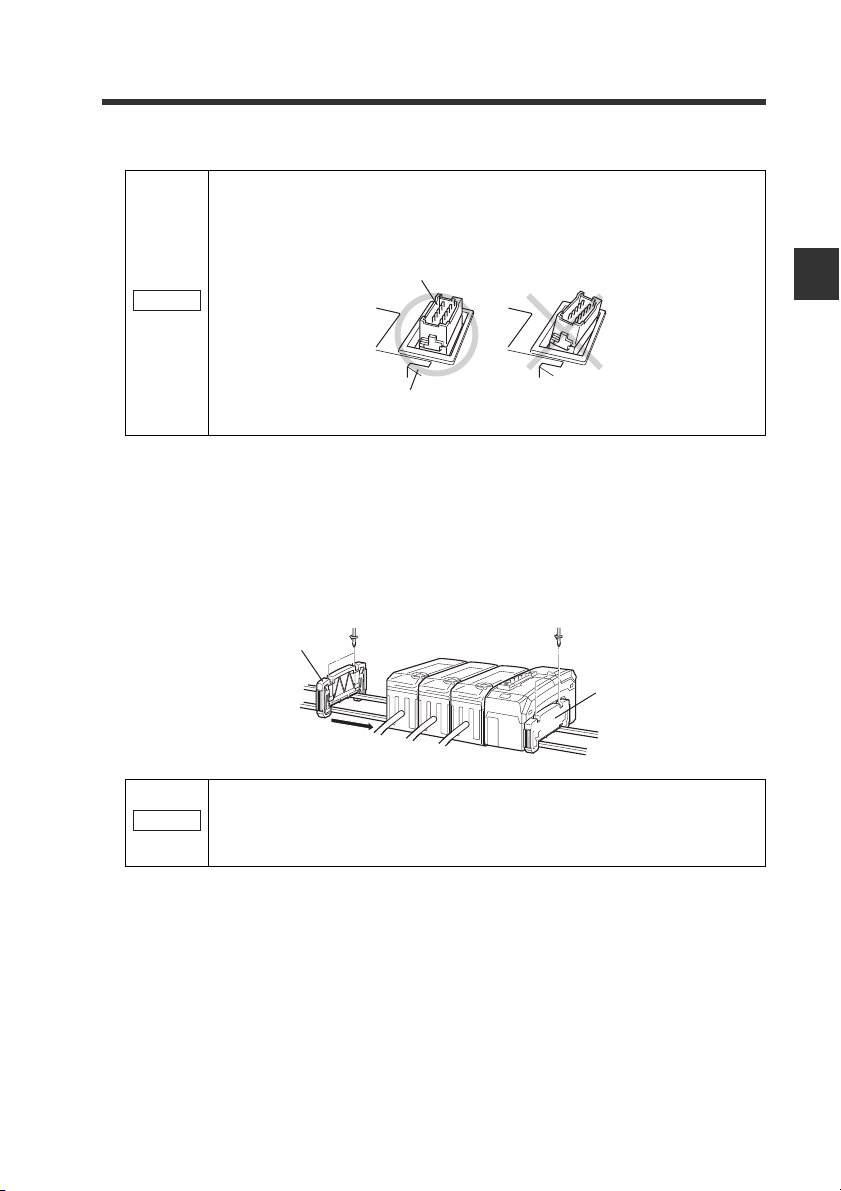
Make sure that the sensor amplifier connector (for DIN rail mounting
type) is not askew on the side face of the CC-Link compatible communication unit DL-CL1, as shown below. If the connector is askew, the DLCL1 may become damaged when connected to the sensor amplifier.
Mount the supplied end units (OP-26751: a set of two pieces) on the outer
3
side faces of the amplifier and the CC-Link compatible communication
unit DL-CL1. Then, fix the end units with the screws on the top of each
end unit (2 points x 2 units). (Tightening torque: 0.6 N•m or less)
Mount the end units in the same way as the CC-Link compatible communication
unit DL-CL1.
2
Connection and Configuration
Press the CC-Link compatible communication unit DL-CL1 into full
engagement with the sensor amplifier. If the DL-CL1 is connected in
slant position or not pressed fully, it may be damaged when the power is
turned on.
- CC-Link Compatible Network Unit DL-CL1 User’s Manual (SK-1000) -
2-5
Page 22
2
Point
Point
Sheath
Shield braid
Approx. 50 mm
Connection and Configuration
2-2
This section describes how to wire the DL-CL1.
Wiring
• Turn off the power before starting the cabling operation.
• For more information about the CC-Link system, including cable
length and cabling methods, refer to the document of the CC-Link
master unit.
Connecting to the CC-Link System
Use the following procedures to connect the DL-CL1 to the CC-Link system.
Usable cables
For connection between the DL-CL1 and the CC-Link system, use CC-Link cables
(Ver. 1.10 or later) accredited by the CC-Link Partner Association.
CC-Link cables (for Ver. 1.10) are available as optional items.
OP-79426 (20 m) OP-79427 (100 m)
To ensure normal communication, only use the CC-Link cables.
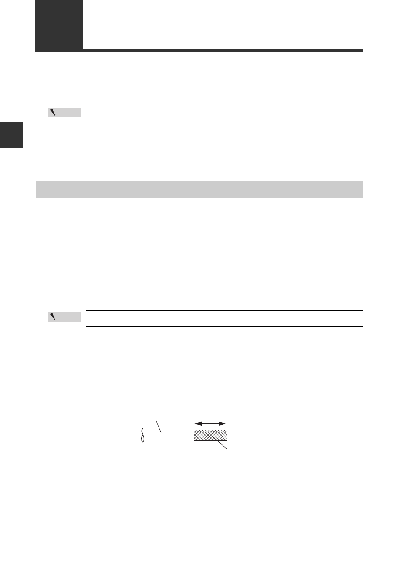
Trimming the cable
Strip the cable sheath.
1
Strip approximately 50 mm of the sheath from the end of the CC-Link cable,
with care to avoid damaging the shield braid of the cable.
2-6
- CC-Link Compatible Network Unit DL-CL1 User’s Manual (SK-1000) -
Page 23
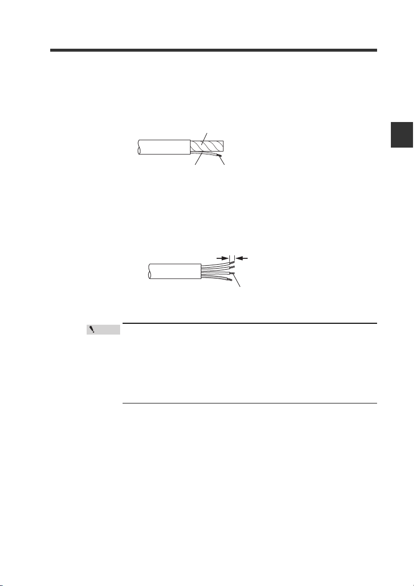
Trim the shield.
Aluminum polyester laminated tape
Insulating tube
Shield braid twisted together
Point
2
Upbraid the shield braid carefully. Find the bare drain wire (twisted or flying)
inside the shield braid. Twist together the unbranded shield braid and the drain
wire securely, and then put on the insulating tube.
Strip the sheathed conductors.
3
Strip approximately 10 mm of sheath from each signal wire, by removing the
aluminum polyester laminated tape. Take care not to damage the signal wires.
Twist together the exposed conductors securely.
Approx. 10 mm
Twist together the conductors
2-2 Wiring
2
Connection and Configuration
- CC-Link Compatible Network Unit DL-CL1 User’s Manual (SK-1000) -
• If you are using solderless terminals, perform cable wiring/
trimming appropriately to suit the specifications of the particular terminals.
Recommended solderless terminals: Phoenix Contact's A/AI
Series
• Do not perform soldering (pre-soldering) on the trimmed end
of the cable.
2-7
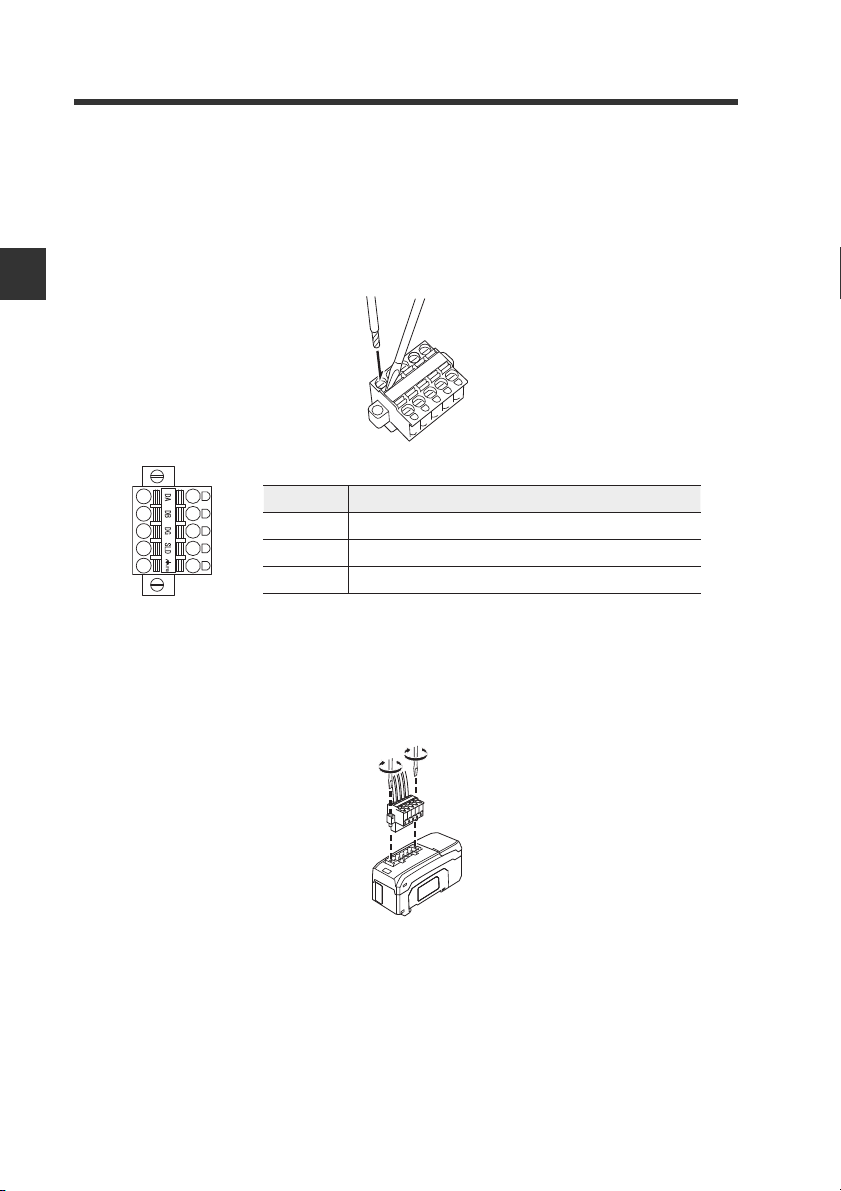
Page 24
2
Terminal name
Function
DA/DB/DG
Communication signal
SLD Connect the shielded wire of the CC-Link cable.
FG
Ground this functional ground terminal according to Class D (Class 3) grounding
Connection and Configuration
2-2 Wiring
Connecting the cable
Use the following procedures to connect to the CC-Link connector supplied with the
DL-CL1.
Connect the trimmed cable to the CC-Link connector.
1
Insert the cable completely.
Attach the CC-Link connector to the DL-CL1.
2
Plug the connector into the DL-CL1 and screw it down with the screws on each
end.
(Tightening torque: 0.2 to 0.3 N•m)
2-8
- CC-Link Compatible Network Unit DL-CL1 User’s Manual (SK-1000) -
Page 25

2-2 Wiring
Connecting the termination resistor
If the DL-CL1 is at the end of the CC-Link system, connect the supplied termination
resistor to DA/DB of the CC-Link connector.
Type of cable Termination resistor
CC-Link Ver. 1.10 compatible cable 110, 1/2 W (brown/brown/
brown/gold)
2
Connection and Configuration
- CC-Link Compatible Network Unit DL-CL1 User’s Manual (SK-1000) -
2-9
Page 26

2
Point
Reference
Reference
Operating mode setting switch
Transmission rate
setting switch
Station number
setting switch
Connection and Configuration
2-3
Use the following configuration procedures for connecting the DL-CL1 to the CC-Link
system.
Configuring the Data Link
This manual covers only the functions and settings of a CC-Link master station which are required for communication with the DL-CL1.
For the functions and settings related to the communication between
the CC-Link master unit and CPU unit, refer to the manuals shipped
with your master unit or CPU unit.
Configuring the Master Station
To connect the DL-CL1 to the CC-Link master unit, it is necessary to configure the
slave attribute and memory allocation settings.
Slave attribute settings
Register the DL-CL1 to the CC-Link master unit as a remote device station.
You can also configure the settings by importing a CSP file into the software for the
master unit (ladder programming software or CC-Link configuration software).
The CSP file can be downloaded from the KEYENCE web site:
http://www.keyence.com
Memory allocation settings
Configuring the DL-CL1
2-10
In order to exchange data between the DL-CL1 and CC-Link master station, configure
the memory allocation settings using the software for the master station (ladder
programming software or CC-Link configuration software).
Where multiple slave units are connected, the memory allocation for each
slave unit is done automatically based on the specified starting address.
The allocation information for each slave unit can be checked using the
CC-Link configuration software.
Use th
e followi
ng procedures to configure the data link of the DL-CL1.
- CC-Link Compatible Network Unit DL-CL1 User’s Manual (SK-1000) -
Page 27

2-3 Configuring the Data Link
Switch setting
Operating mode
Station
configuration
Number of link points
RX/R Y
RW w/ RW r
Small-memory mode 1
(1-output, 1-input)
1-station, 1x
32
4
Small-memory mode 2
(3-output, 3-input)
64
8
Monitor mode 1
(5-output, 5-input, current value,
BANK change)
128
16
128
32
Full mode 1
(5-output, 5-input, current value,
BANK change, setting value change)
384
64
Others Cannot be set −
224
32
2-station, 1x
4-station, 1x
1-station, 8x
4-station, 2x
2-station, 8x
Monitor mode 2
(5-output, 5-input, current value,
BANK change)
Full mode 2
(5-output, 5-input, current value,
BANK change, setting value change)
Setting the transmission rate
Set the transmission rate of the DL-CL1 to the same value as set in the CC-Link
master station.
Do this using the transmission rate setting switch on the DL-CL1.
• Default value: 0
No. 0 1 2 3 4 5 to 9
Transmission rate (bps) 156 k 625 k 2.5 M 5 M 10 M
Cannot be set.
Setting the station number
Using the station address setting switch, set the station number (slave ID) assigned to
the DL-CL1.
• Default value: 01
• Setting range: 01 to 64
Selecting an operating mode
Using the operating mode setting switch, set the combination of the number of
stations occupied by the DL-CL1 and the extended cyclic setting. The specific data
that can be communicated using cyclic transfer varies with each operating mode.
See the section "Selecting an Operating Mode of the DL-CL1" and select the
appropriate operating mode that suits the desired function of sensor amplifiers.
• Default value: Small-memory mode 1
• The contents of output and current value vary depending on the sensor amplifiers
to be connected.
Ex
amples: 3-l
evel judgment output for 3-output mode; 5-level judgment output for
5-output mode. Current value: judgment value.
2
Connection and Configuration
- CC-Link Compatible Network Unit DL-CL1 User’s Manual (SK-1000) -
2-11
Page 28

2
Point
Connection and Configuration
2-3 Configuring the Data Link
Each switch should be set before turning on the power. If any setting
is changed while the DL-CL1 is operating, the new setting will not be
applied until the power is turned on again. (The communication error
indicator flashes intermittently.)
2-12
- CC-Link Compatible Network Unit DL-CL1 User’s Manual (SK-1000) -
Page 29

Communicating with the SK-1000
Series
This chapter describes the configuration of the memory linked to the
CC-Link master station and provides communication time charts.
3-1 CC-Link Communication and Operating Modes. 3-2
3-2 Device Maps....................................................... 3-4
3-3 Communication Methods.................................. 3-18
3-4 Command Parameter List ................................3-26
3
- CC-Link Compatible Network Unit DL-CL1 User’s Manual (SK-1000) -
3-1
Page 30

3
(1) RX (Remote inputs)
(3)
RWr (Remote registers)
(2) RY (Remote inputs)
(4)
RWw (Remote registers)
Output
Judgment value
Error information
Read parameter
Request to change setting value
Changed setting value
External input
Write parameter
CC-Link master station
DL-CL1
Sensor amplifier
Output
Judgment value
・・・・・・
・・・・・・
・・・・・・
・・・・・・
・・・・・・
Error information
設定値
外部
Output
Judgment value
・・・・・・
・・・・・・
・・・・・・
・・・・・・
・・・・・・
・・・・・・
Error information
設定値
外部
Output
Judgment value
・・・・・・
・・・・・・
・・・・・・
・・・・・・
・・・・・・
Error information
Setting value
External input
Read/write parameters
Communicating with the SK-1000 Series
3-1
CC-Link Communication and Operating Modes
The DL-CL1 operates as a remote device station of a CC-Link system.
This section describes the data that the DL-CL1 can exchange through the CC-Link,
and available operating modes.
Data Exchanged by Cyclic Transfer
The DL-CL1's data is linked with the CC-Link maser station as shown below.
Through the link, the CC-Link master station is enabled to:
• Communicate the output signal, judgment value, and error status of sensor amplifiers without the need of a ladder program.
• Use the remote input RX and remote output RY areas as handshake signals to
execute external inputs to, or change the setting values of, sensor amplifiers.
• Execute motion commands on sensor amplifiers.
• Directly read and write the parameters of sensor amplifiers. This capability gives
the ability to use functions that can be executed on sensor amplifiers.
3-2
- CC-Link Compatible Network Unit DL-CL1 User’s Manual (SK-1000) -
Page 31

3-1 CC-Link Communication and Operating Modes
Selecting an Operating Mode of the DL-CL1
Select an operating mode of the DL-CL1 to suit the functions of the sensor amplifiers
to be used.
The specific CC-Link device configuration and the data that can be communicated
using cyclic transfer vary with each operating mode of the DL-CL1. An appropriate
operating mode should be determined by considering the number of link points the
data that can be communicated.
"Configuring the Data Link" (page 2-10)
Operating mode of DL-CL1
Small-
Small-
Monitor
Method of
communication
with the master
station
Remote input RX Read out-
Remote register RWr Read judgment
Remote output RY External
Remote register
RWw
Handshake control
*3
program
(Command commu-
nication)
Yes: Available with sensor amplifiers of ID 01 to 08. No: Not available.
*1 For details of the functions assigned for motions commands and setting/status read/write,
see "Device Maps" (page 3-4) and "Command Parameter List" (page 3-26).
*2 In remote register RWw, specify the ID number of the sensor amplifier from which to read.
*3 To use this communication method, create a program that controls commands by handshaking
Available function
of sensor
amplifier
puts 1 - 5
value (P.V. value)
inputs 1-5
Change BANK number
Rewrite setting
value
Motion command No No Yes Yes Yes Yes 3-22
Read output
Read judgment
value (P.V. value)
Read external input
status
Read BANK number
Read setting/status
Write setting/status
memory
memory
mode 1
*1
1-station, 1x2-station, 1x4-station, 1x1-station, 8x4-station, 2x2-station,
HI Yes Yes Yes Yes Yes Yes 3-4
LO No Yes Yes Yes Yes Yes
GO No Yes Yes Yes Yes Yes
Alarm
output
Not
used
External
input 1
External
input 2
External
input 3
External
input 4
Not
used
mode 2
page 3-4 page 3-12
No No Yes Yes Yes Yes
– – – – – –
No No
Yes Yes Yes Yes Yes Yes
No Yes Yes Yes Yes Yes
No Yes Yes Yes Yes Yes
No No Yes Yes Yes Yes
– – – – – –
No No Yes Yes Yes Yes 3-17
No No No No Yes Yes
No No Yes Yes Yes Yes
mode 1
Yes
Monitor
mode 2
*2
between a remote input/output and remote register.
Full
mode 1
Yes Yes Yes
Full
mode 2
8x
Reference
page for
communication
method
3-7
3-14
3-17
3-18
3
Communicating with the SK-1000 Series
- CC-Link Compatible Network Unit DL-CL1 User’s Manual (SK-1000) -
3-3
Page 32

3
3-2
Device Maps
The device maps vary as described in "Selecting an Operating Mode of the DLCL1" (page 3-3). Select an operating mode suited for the functions of the sensor
amplifiers to be used, before accessing each device.
Device Maps for Small-Memory Mode 1, Small-Memory Mode 2, and Monitor Mode 1
The following device maps are used for when the operating mode is small-memory
mode 1, small-memory mode 2, or monitor mode 1.
In cases of monitor mode 2, full mode 1, and full mode 2, see "Device Maps for
Monitor Mode 2, Full Mode 1, and Full Mode 2" (page 3-12).
Communicating with the SK-1000 Series
Remote input RX (DL-CL1 -> master station)
Operating
mode
Small-memory mode 1
Device no.
Small-memory mode 2
(HEX)
Monitor mode 1
RX[n] + 00
to 07
RX[n] + 0F Error status-
RX[n] + 10
to 17
RX[n] + 1F (Not used) - - -
RX[n] + 20
to 27
RX[n] + 2F
RX[n] + 30
to 37
RX[n] + 3F
RX[n] + 40
to 4E
RX[n] + 4F
RX[n] + 50 Sensor ready *4
RX[n] + 51
Name
HI ID 01
to ID 08
LO ID 01
to ID 08
GO ID01
to ID08
System reserved
Alarm output
ID 01 to ID 08
System reserved
(Not used)
ID 01 to ID 08
System reserved
Command
complete
Communication
method
*1
*1
*1
- Unusable -
*1 -
- Unusable -
- - -
- Unusable -
*4
Description Reading range
Sends the HI output state (ON/
OFF) of the sensor amplifier.
The HI output of each sensor
amplifier (ID 01 to ID 08)
corresponds to each RX.
The DL-CL1 is not communicating
properly with the sensor amplifier,
or an error exists with the sensor
amplifier.
If an error exists, the error code is
stored in error code (RWr[n] + 00).
Sends the LO output state (ON/
OFF) of the sensor amplifier.
The LO output of each sensor
amplifier (ID 01 to ID 08)
corresponds to each RX.
Sends the GO output state (ON/
OFF) of the sensor amplifier.
The GO output of each sensor
amplifier (ID 01 to ID 08)
corresponds to each RX.
Used when communicating under
handshake control program.
This is output when command
execution is ready.
Used when communicating under
handshake control program.
This is output when command
execution is complete.
0: OFF
1: ON
0: No error
1: Error
0: OFF
1: ON
0: OFF
1: ON
0: OFF
1: ON
0: In preparation
1: Ready
0->1:
Execution
complete
3-4
- CC-Link Compatible Network Unit DL-CL1 User’s Manual (SK-1000) -
Page 33

3-2 Device Maps
Operating
mode
Device no.
(HEX)
Monitor mode 1
RX[n] + 52 Command error *4
RX[n] + 53
RX[n] + 54
to 5D
RX[n] + 5E
RX[n] + 5F
RX[n] + 60
to 67
RX[n] + 6F
RX[n] + 1B
RX[n] + 3B
RX[n] + 7B
Name
Judgment value
update lock
state
System reserved
Judgment value
page change
complete
Judgment value
page change
error
BANK change
complete ID 01
to ID 08
BANK change
error
Remote ready
Communication
method
-
- Unusable -
*2
*2
*3
*3
-
Description Reading range
Used when communicating under
handshake control program.
This is output when an error occurs
during command execution.
This is output when judgment
value (P.V. value) update is locked
(judgment value update lock
request (RY[n] + 53) is ON).
Used when reading judgment
value (P.V. value).
This is output when judgment
value page has been changed.
Used when reading judgment
value (P.V. value).
This is output if an error occurs
while changing the judgment value
page.
Used when changing BANK
number.
This is output when BANK number
has been changed.
The output of each sensor amplifier (ID
01 to ID 08) corresponds to each RX.
Used when changing BANK
number.
This is output if an error occurs
with a sensor amplifier of any ID
number during BANK number
changing.
This is output when the DL-CL1 is
correctly connected to th e CC-Link
system.
1: Proper communication is
provided. Data from the sensor
amplifier will be updated.
0: Proper communication is not
provided. Data from the sensor
amplifier will not be updated.
0: No error
1: Error
0: Update enabled
1: Update locked
0->1: Change
complete
0: No error
1: Error
0->1: Change
complete
0: No error
1: Error
0: In preparation
1: Ready
3
Communicating with the SK-1000 Series
Number [n] denotes the first relay number assigned to the DL-CL1.
*1 Refer to "Reading an Output from a Sensor Amplifier" (page 3-18).
*2 Refer to "Monitor mode 1" (page 3-19).
*3 Refer to "Changing the BANK Number of Sensor Amplifiers" (page 3-21).
*4 Refer to "Reading/Writing Settings or Status of a Sensor Amplifier" (page 3-23).
*5 Refer to "Issuing a Motion Command to a Sensor Amplifier" (page 3-22).
- CC-Link Compatible Network Unit DL-CL1 User’s Manual (SK-1000) -
3-5
Page 34

3-2 Device Maps
Remote output RY (master station -> DL-CL1)
Operating
mode
Small-memory mode 1
Device no.
Small-memory mode 2
(HEX)
Monitor mode 1
Name
Communication
method
Description Writing range
3
Communicating with the SK-1000 Series
RY[n] + 00
to 07
RY[n] + 0F
RY[n] + 10
to 17
RY[n] + 1F
RY[n] + 20
to 27
RY[n] + 2F
RY[n] + 30
to 37
RY[n] + 3F
RY[n] + 40
to 4E
RY[n] + 4F
to 50
RY[n] + 51
RY[n] + 52
RY[n] + 53
RY[n] + 54
to 5D
RY[n] + 5E
RY[n] + 5F
External output-
1 ID 01 to ID 08
System reserved
External output-
1 ID 01 to ID 08
System reserved
External input-3
ID 01 to ID 08
System reserved
External input-4
ID 01 to ID 08
System reserved
(Not used)
ID 01 to ID 08
System reserved
Request for
command
System reserved
Request to lock
judgment value
update
System reserved
Request to
change
judgment value
page
System reserved
Receives external input-1 by
*1
assigning each sensor amplifier
(ID 01 to ID 08) to each RY.
- Unusable -
Receives external input-2 by
*1
assigning each sensor amplifier
(ID 01 to ID 08) to each RY.
- Unusable -
Receives external input-3 by
*1
assigning each sensor amplifier
(ID 01 to ID 08) to each RY.
- Unusable -
Receives external input-4 by
*1
assigning each sensor amplifier
(ID 01 to ID 08) to each RY.
- Unusable -
- - -
- Unusable -
Used when communicating under
handshake control program.
*4
This is input when requesting
command execution.
- Unusable -
Used to lock data update in
judgment value boxes (RWr[n] +
08 to 0D).
This may be used to obtain the
judgment values of multiple sensor
-
amplifiers at the same timing.
The judgment value is locked while
the update request is held.
The update lock state can be
checked by the judgment value
update lock state (RX[n] + 53).
- Unusable -
Used when reading judgment
value (P.V. value).
This is input when requesting to
*2
change the judgment value page
(the ID number of the sensor
amplifier to read from).
- Unusable -
0: OFF
1: ON
0: OFF
1: ON
0: OFF
1: ON
0: OFF
1: ON
0->1: Request
execution
0: Do not lock
update
1: Request
update lock
0->1: Request
change
3-6
- CC-Link Compatible Network Unit DL-CL1 User’s Manual (SK-1000) -
Page 35

3-2 Device Maps
Operating
mode
Monitor mode 1
RY[n] + 60
to 67
RY[n] + 6F
Device no.
(HEX)
Name
Request to
change BANK
ID 01 to ID 08
Clear BANK
error
Communication
method
*3
*3
Description Writing range
Used when changing BANK
number.
This is input when requesting to
change the BANK number of each
sensor amplifier.
The request input is received by
assigning each sensor amplifier
(ID 01 to ID 08) to each RY.
Used when changing BANK
number.
This is input when clearing a
BANK change error.
Number [n] denotes the first relay number assigned to the DL-CL1.
*1 Refer to "Entering an External Input into a Sensor Amplifier" (page 3-18).
*2 Refer to "Monitor mode 1" (page 3-19).
*3 Refer to "Changing the BANK Number of Sensor Amplifiers" (page 3-21).
*4 Refer to "Reading/Writing Settings or Status of a Sensor Amplifier" (page 3-23).
Refer to "Issuing a Motion Command to a Sensor Amplifier" (page 3-22).
Remote register RWr (DL-CL1 -> master station)
Operating
mode
Small-memory mode 1
Device no.
Small-memory mode 2
(HEX)
Monitor mode 1
RWr[n] + 00 Er ror code -
RWr[n] + 01
RWr[n] + 02
to 03
RWr[n] + 04
RWr[n] + 05
RWr[n] + 06
Name
Command
response
Read data *3
External input-1
response
External input-2
response
External input-3
response
Communication
method
*3
*1
*1
*1
Description Reading range
Stores an error code when error
status (RX[n] + 0F) turns ON.
If there are multiple errors, the
error having the smallest number
(two last digits in HEX) is stored. If
there are errors with multiple ID
numbers, the error information for
the smallest ID number is stored.
Used when communicating under
handshake control program.
Stores details of command
execution result.
Used when communicating under
handshake control program.
Stores the parameter data read
from the sensor amplifier.
Stores the external input-1
response of the sensor amplifier.
The response is output by
assigning sensor amplifiers (ID 01
to ID 08) to bits 0 - 07.
Stores the external input-2
response of the sensor amplifier.
The response is output by
assigning sensor amplifiers (ID 01
to ID 08) to bits 0 - 07.
Stores the external input-3
response of the sensor amplifier.
The response is output by
assigning sensor amplifiers (ID 01
to ID 08) to bits 0 - 07.
0->1: Request
change
0->1: Clear error
*5
*6
*7
0: Input OFF
1: Input ON
0: Input OFF
1: Input ON
0: Input OFF
1: Input ON
3
Communicating with the SK-1000 Series
- CC-Link Compatible Network Unit DL-CL1 User’s Manual (SK-1000) -
3-7
Page 36

3-2 Device Maps
3
Communicating with the SK-1000 Series
Operating
mode
Device no.
(HEX)
Monitor mode 1
RWr[n] + 07
RWr[n] + 08
to 09
RWr[n] + 0A
to 0B
RWr[n] + 0C
to 0D
RWr[n] + 0E
RWr[n] + 0F (Not used) - - -
Name
Judgment value
property
Judgment value
box 1
Judgment value
box 2
Judgment value
box 3
External input-4
response
Communication
method
*2
*2
*2
*2
*1
Description Reading range
Used when reading judgment
value (P.V. value).
This property is output by
assigning IDs (ID 01 to ID 08) to
bits 0 - 07.
The output occurs when the
judgment value (P.V. value) read
from the sensor amplifier is
nonnumeric: "over," "under," or
"invalid."
Used when reading judgment
value (P.V. value).
The judgment value (P.V. value) of
the sensor amplifier of the ID
number specified page number
(RWw[n] + 08) is output.
Data type: INT32 (LITTLE)
Used when reading judgment
value (P.V. value).
The judgment value (P.V. value) of
the sensor amplifier of the ID
number specified page number
(RWw[n] + 08) is output.
Data type: INT32 (LITTLE)
Used when reading judgment
value (P.V. value).
The judgment value (P.V. value) of
the sensor amplifier of the ID
number specified page number
(RWw[n] +08) is output.
Data type: INT32 (LITTLE)
Stores the external input-4
response of the sensor amplifier.
The response is output by
assigning sensor amplifiers (ID 01
to ID 08) to bits 0 - 07.
Number [n] denotes the first relay number assigned to the DL-CL1.
*1 Refer to "Entering an External Input into a Sensor Amplifier" (page 3-18).
*2 Refer to "Monitor mode 1" (page 3-19).
*3 Refer to "Reading/Writing Settings or Status of a Sensor Amplifier" (page 3-23).
Refer to "Issuing a Motion Command to a Sensor Amplifier" (page 3-22).
*4 Refer to "Monitor mode 2/full mode" (page 3-20).
*5 Refer to "Error information list" (page 3-9).
*6 Refer to "Command response list" (page 3-10).
*7 Refer to "Command Parameter List" (page 3-26).
0: Normal
judgment value
1: "over," "under,"
or "invalid (-----)"
Page 0: ID 01
Page 1: ID 04
Page 2: ID 07
Page 0: ID 02
Page 1: ID 05
Page 2: ID 08
Page 0: ID 03
Page 1: ID 06
Page 2: Not used
0: Input OFF
1: Input ON
3-8
- CC-Link Compatible Network Unit DL-CL1 User’s Manual (SK-1000) -
Page 37

Error information list
Error Information
*
(HEX)
0000 No error - -
0001
0002
0005
0003 Model error
0004 Mixed connection error
0006 Number-of-units error
0007
nn01
nn02
nn03
nn04 to nn07
nn08
nn09 to nn0B
nn0c
nn0D to nn10
* "nn" denotes the ID number in hexadecimal of sensor amplifier.
(Example: 01h for ID 01, ..., 04h for ID 04)
If there are multiple errors, the smallest error code is stored in the remote register.
Description Cause Corrective action
Initialization error
Sensor-to-sensor
communication error
Error 1 for sensor amplifier
of ID number nn
Error 2 for sensor amplifier
of ID number nn
Error 3 for sensor amplifier
of ID number nn
Error 4 to 7 for sensor
amplifier of ID number nn
Error 8 for sensor amplifier
of ID number nn
Error 9 to 11 for sensor
amplifier of ID number nn
Error 12 for sensor amplifier
of ID number nn
Error 13 to 16 for sensor
amplifier of ID number nn
Error encountered during
initialization.
There is connected a sensor
amplifier of a model
incompatible with the DL-CL1.
A foreign sensor amplifier (i.e.,
one that cannot be intermixed)
is connected.
More sensor amplifiers are
connected than are permitted.
An error exists in the
communication between
sensor
amplifiers.
Overcurrent error
EEPROM error
Head error
(Not used)
Head temperature/humidity
error
(Not used)
Amp-to-Amp communication
error
(Not used)
3-2 Device Maps
Check the number of connected
sensor amplifiers and the
connection to the sensor
amplifiers, and then turn off the
power and back on. If the error
cannot be recovered, contact
your nearest sales office.
Connect a sensor amplifier of a
compatible model.
Remove the foreign sensor
amplifier.
Observe the number of
connectable sensor amplifiers.
Check the connections of the
sensor amplifiers, and then turn
off the power and back on.
Refer to the SK-1000 series
instruction manual.
3
Communicating with the SK-1000 Series
- CC-Link Compatible Network Unit DL-CL1 User’s Manual (SK-1000) -
3-9
Page 38

3
3-2 Device Maps
Command response list
Response
(HEX)
0000 Successfully completed The command has been processed successfully.
0001 Command number error The command number is out of range.
0002 Data category error The data category value is out of range.
0003 ID number out of range The ID number of sensor amplifier is out of range.
0004 Data number out of range The data number is out of range.
0005 Write inhibit Read-only data number. Cannot be written.
0006 Write data out of range Data written is out of range.
0007 Sensor -to-sensor communication error An error exists in the communication between sensors.
0008 Motion command access error Cannot read/write to motion command data numbers.
Communicating with the SK-1000 Series
0009
000A Motion command execution error Failed to execute the motion command.
000B Read inhibit Write-only data number. Cannot be read.
000C Operating status error
FFFF(-1)
FFFE(-2)
……
FFF7(-9)
FFF6(-10)
* This response is provided specifically for data category 10. If the read data has decimal-point position
information and the command is successfully processed, the decimal-point position information is
added to the command response. For details of data category 10, refer to "Command Parameter
List" (page 3-26).
Name Description
Motion command data number out of
range
Decimal point position of read data*
The data number of motion command is out of range.
Command communication (read or write) is
temporarily prohibited because of the operating status
of the sensor amplifier.
The command has been processed successfully.
The data being read has one decimal place.
********. *
The command has been processed successfully.
The data being read has two decimal places.
********. **
The command has been processed successfully.
The data being read has nine decimal places.
*. *********
The command has been processed successfully.
The data being read has ten decimal places.
0. **********
Remote register RWw (master station -> DL-CL1)
3-10
Operating
mode
Small-memory mode 1
Device no.
Small-memory mode 2
(HEX)
Monitor mode 1
RWw[n] + 00
RWw[n] + 01 Data number *3
RWw[n] + 02
to 03
Name
Data category/
command
number
Data to write *3
Communication
method
*3
Used when communicating under
handshake control program.
Specifies the data category and
command number of the
parameter to be communicated.
Used when communicating under
handshake control program.
Specifies the data number of the
parameter to be communicated.
Used when communicating under
handshake control program.
Specifies the data to be written in
the parameter to be
communicated.
- CC-Link Compatible Network Unit DL-CL1 User’s Manual (SK-1000) -
Description Writing range
Upper byte:
00h - FFh
Lower byte:
00: Read
01: Write
02: Motion
command
0000h - FFFFh
*4
Page 39

3-2 Device Maps
Operating
mode
Device no.
Monitor mode 1
RWw[n] + 04
RWw[n] + 05
to 07
RWw[n] + 08
(HEX)
Name
Select BANK
number
System reserved
Select
judgment value
box page
number
Communication
method
*2
- Unusable -
*1
Description Writing range
Used when changing BANK
number.
Specifies a new BANK number.
Used when reading judgment
value (P.V. value).
Specifies the page number
corresponding to the sensor
amplifier ID number to be stored in
the
judgment value box.
Number [n] denotes the first relay number assigned to the DL-CL1.
*1 Refer to "Monitor mode 1" (page 3-19).
*2 Refer to "Changing the BANK Number of Sensor Amplifiers" (page 3-21).
*3 Refer to "Reading/Writing Settings or Status of a Sensor Amplifier" (page 3-23).
Refer to "Issuing a Motion Command to a Sensor Amplifier" (page 3-22).
*4 Refer to "Command Parameter List" (page 3-26).
0: BANK 0
1: BANK 1
2: BANK 3
3: BANK 3
0: Page 0
1: Page 1
2: Page 2
3: Page 3
4: Page 4
3
Communicating with the SK-1000 Series
- CC-Link Compatible Network Unit DL-CL1 User’s Manual (SK-1000) -
3-11
Page 40

3
3-2 Device Maps
Device Maps for Monitor Mode 2, Full Mode 1, and Full Mode 2
The following device maps are used when the operating mode is monitor mode 2, full
mode 1, or full mode 2.
In cases of small-memory mode 1, small-memory mode 2, and monitor mode 1,
see "Device Maps for Small-Memory Mode 1, Small-Memory Mode 2, and Monitor
Mode 1" (page 3-4).
Remote input RX (DL-CL1 -> master station)
Communicating with the SK-1000 Series
Operating
mode
Monitor mode 2
Device no.
Full mode 1
(HEX)
Full mode 2
RX[n] + 00
to 07
RX[n] + 0F Error status -
RX[n] + 10
to 17
RX[n] + 1F Not used - - -
RX[n] + 20
to 27
RX[n] + 2F
RX[n] + 30
to 37
RX[n] + 3F
RX[n] + 40
to 4E
RX[n] + 4F
RX[n] + 50 Sensor ready *3
RX[n] + 51
RX[n] + 52 Command error *3
RX[n] + 53
RX[n] + 54
to 5D
Name
HI ID 01
to ID 08
LO ID01
to ID08
GO ID01
to ID08
System reserved
Alarm output
ID 01 to ID 08
System reserved
Not used
ID 01 to ID 08
System reserved
Command
complete
Judgment value
update lock
state
System
reserved
Communication
method
*1
*1
*1
- Unusable -
*1 -
- Unusable -
- - -
- Unusable -
*3
-
- Unusable -
Description Reading range
Sends the HI output state (ON/
OFF) of the sensor amplifier.
The HI output of each sensor
amplifier (ID 01 to ID 08)
corresponds to each RX.
The DL-CL1 is not communicating
properly with the sensor amplifier,
or an error exists with the sensor
amplifier.
If an error exists, the error code is
stored in error code (RWr[n] + 00).
Sends the LO output state (ON/
OFF) of the sensor amplifier.
The LO output of each sensor
amplifier (ID 01 to ID 08)
corresponds to each RX.
Sends the GO output state (ON/
OFF) of the sensor amplifier.
The GO output of each sensor
amplifier (ID 01 to ID 08)
corresponds to each RX.
Used when communicating under
handshake control program.
This is output when command
execution is ready.
Used when communicating under
handshake control program.
This is output when command
execution is complete.
Used when communicating under
handshake control program.
This is output when an error occurs
during command execution.
This is output when judgment
value update is locked (judgment
value update lock request (RY[n] +
53) is ON).
0: OFF
1: ON
0: No error
1: Error
0: OFF
1: ON
0: OFF
1: ON
0: OFF
1: ON
0: In preparation
1: Ready
0->1: Execution
complete
0: No error
1: Error
0: Update
enabled
1: Update locked
3-12
- CC-Link Compatible Network Unit DL-CL1 User’s Manual (SK-1000) -
Page 41

3-2 Device Maps
Operating
mode
Monitor mode 2
Full mode 1
Device no.
Full mode 2
RX[n] + 60
to 67
RX[n] + 6F
RX[n] + 70
to 77
RX[n] + 7F
RX[n] + 80
to 87
RX[n] + 8F
RX[n] + 7B
RX[n] + DB
RX[n] + 17B
(HEX)
Name
BANK change
complete ID 01
to ID 08
BANK change
error
HI setting value
(BANK 0)
rewrite
complete ID 01
to ID 08
HI setting value
(BANK 0)
rewrite error
LO setting
value (BANK 0)
rewrite
complete ID 01
to ID 08
LO setting
value (BANK 0)
rewrite error
Remote ready -
Communication
method
Used when changing BANK
number.
This is output when BANK number
*3
has been changed.
The output of each sensor
amplifier (ID 01 to ID 08)
corresponds to each RX.
Used when changing BANK
number.
This is output if an error occurs
*3
with a sensor amplifier of any ID
number during BANK number
changing.
Used when rewriting a setting
value.
This is output when the HI setting
value (BANK 0) has been
*5
changed.
The output of each sensor
amplifier (ID 01 to ID 08)
corresponds to each RX.
Used when rewriting a setting
value.
This is output if an error occurs
*5
with a sensor amplifier of any ID
number during rewriting of HI
setting value (BANK 0).
Used when rewriting a setting
value.
This is output when the LO setting
value (BANK 0) has been
*5
changed.
The output of each sensor
amplifier (ID 01 to ID 08)
corresponds to each RX.
Used when rewriting a setting
value.
This is output if an error occurs
*5
with a sensor amplifier of any ID
number during rewriting of LO
setting value (BANK 0).
This is output when the DL-CL1 is
correctly connected to th e CC-Link
system.
1: Proper communication is
provided. Data from the sensor
amplifier will be updated.
0: Proper communication is not
provided. Data from the sensor
amplifier will not be updated.
Description Reading range
0->1: Change
complete
0: No error
1: Error
0->1: Rewrite
complete
0: No error
1: Error
0->1: Rewrite
complete
0: No error
1: Error
0: In preparation
1: Ready
3
Communicating with the SK-1000 Series
Number [n] denotes the first relay number assigned to the DL-CL1.
*1 Refer to "Reading an Output from a Sensor Amplifier" (page 3-18).
*2 Refer to "Monitor mode 1" (page 3-19).
*3 Refer to "Changing the BANK Number of Sensor Amplifiers" (page 3-21).
*4 Refer to "Reading/Writing Settings or Status of a Sensor Amplifier" (page 3-23).
*5 Refer to "Issuing a Motion Command to a Sensor Amplifier" (page 3-22).
- CC-Link Compatible Network Unit DL-CL1 User’s Manual (SK-1000) -
3-13
Page 42

3
3-2 Device Maps
Remote output RY (master station -> DL-CL1)
Operating
Communicating with the SK-1000 Series
Monitor mode 2
mode
Full mode 1
Full mode 2
RY[n] + 00
to 07
RY[n] + 0F
RY[n] + 10
to 17
RY[n] + 1F
RY[n] + 20
to 27
RY[n] + 2F
RY[n] + 30
to 37
RY[n] + 3F
RY[n] + 40
to 4E
RY[n] + 4F
to 50
RY[n] + 51
RY[n] + 52
RY[n] + 53
RY[n] + 54
to 5F
RY[n] + 60
to 67
RY[n] + 6F
RY[n] + 70
to 77
Device no.
(HEX)
Name
External input-1
ID 01 to ID 08
System reserved
External input-2
ID 01 to ID 08
System reserved
External input-3
ID 01 to ID 08
System reserved
External input-1
ID 01 to ID 08
System reserved
(Not used)
ID 01 to ID 08
System reserved
Request for
command
System reserved
Request to lock
judgment value
update
System reserved
Request to
change BANK
ID 01 to ID 08
Clear BANK
error
HI setting value
(BANK 0)
rewrite request
ID 01 to ID 08
Communication
method
*1
- Unusable -
*1
- Unusable -
*1
- Unusable -
*1
- Unusable -
- - -
- Unusable
*3
- Unusable -
-
- Unusable -
*3
*3
*5
Description Writing range
Receives external input-1 by
assigning each sensor amplifier
(ID 01 to ID 08) to each RY.
Receives external input-2 by
assigning each sensor amplifier
(ID 01 to ID 08) to each RY.
Receives external input-3 by
assigning each sensor amplifier
(ID 01 to ID 08) to each RY.
Receives external input-4 by
assigning each sensor amplifier
(ID 01 to ID 08) to each RY.
Used when communicating under
handshake control program.
This is input when requesting
command execution.
Used when locking data update of
judgment value.
This may be used to obtain the
judgment values of multiple sensor
amplifiers at the same timing.
The judgment value is locked while
the update request is held.
The update lock state can be
checked by the judgment value
update lock state (RX[n] + 53).
Used when changing BANK
number.
This is input when requesting to
change the BANK number of each
sensor amplifier.
The request input is received by
assigning each sensor amplifier
(ID 01 to ID 08) to each RY.
Used when changing BANK
number.
This is input when clearing a
BANK change error.
Used when rewriting a setting
value.
This is input when requesting to
rewrite the HI setting value (BANK
0) of each sensor amplifier.
The request input is received by
assigning each sensor amplifier
(ID 01 to ID 08) to each RY.
0: OFF
1: ON
0: OFF
1: ON
0: OFF
1: ON
0: OFF
1: ON
-
0->1: Request
execution
0: Do not lock
update
1: Request
update lock
0->1: Request
change
0->1: Clear error
0->1: Request to
rewrite
3-14
- CC-Link Compatible Network Unit DL-CL1 User’s Manual (SK-1000) -
Page 43

Operating
Monitor mode 2
mode
Full mode 1
Device no.
Full mode 2
RY[n] + 7F
RY[n] + 80
to 87
RY[n] + 8F
(HEX)
Name
Clear HI setting
value (BANK 0)
rewrite error
LO setting
value (BANK 0)
rewrite request
ID 01 to ID 08
Clear LO
setting value
(BANK 0)
rewrite error
Communication
method
*5
*5
*5
Description Writing range
Used when rewriting a setting
value.
This is input when clearing a HI
setting-value (BANK 0) rewrite
error.
Used when rewriting a setting
value.
This is input when requesting to
rewrite the LO setting value (BANK
0) of each sensor amplifier.
The request input is received by
assigning each sensor amplifier
(ID 01 to ID 08) to each RY.
Used when rewriting a setting
value.
This is input when clearing a LO
setting-value (BANK 0) rewrite
error.
Number [n] denotes the first relay number assigned to the DL-CL1.
*1 Refer to "Entering an External Input into a Sensor Amplifier" (page 3-18).
*2 Refer to "Monitor mode 1" (page 3-19).
*3 Refer to "Changing the BANK Number of Sensor Amplifiers" (page 3-21).
*4 Refer to "Reading/Writing Settings or Status of a Sensor Amplifier" (page 3-23).
Refer to "Issuing a Motion Command to a Sensor Amplifier" (page 3-22).
*5 Refer to "Rewriting a Setting Value of a Sensor Amplifier" (page 3-23).
Remote register RWr (DL-CL1 -> master station)
Operating
mode
Monitor mode 1
Device no.
Full mode 1
(HEX)
Full mode 2
RWr[n] + 00 Er ror code -
RWr[n] + 01
RWr[n] + 02
to 03
(2 words)
RWr[n] + 04
RWr[n] + 05
Name
Command
response
Read data *3
External input-1
response
External input-2
response
Communication
method
*3
*1
*1
Description Reading range
Stores an error code when error
status (RX[n] + 0F) turns ON.
If there are multiple errors, the
error having the smallest number
(two last digits in HEX) is stored. If
there are errors with multiple ID
numbers, the error information for
the smallest ID number is stored.
Used when communicating under
handshake control program.
Stores details of command
execution result.
Used when communicating under
handshake control program.
Stores the parameter data read
from the sensor amplifier.
Stores the external input-1
response of the sensor amplifier.
The response is output by
assigning sensor amplifiers (ID 01
to ID 08) to bits 0 - 07.
Stores the external input-2
response of the sensor amplifier.
The response is output by
assigning sensor amplifiers (ID 01
to ID 08) to bits 0 - 07.
3-2 Device Maps
0->1: Clear error
0->1: Request to
rewrite
0->1: Clear error
*5
*6
*7
0: Input OFF
1: Input ON
0: Input OFF
1: Input ON
3
Communicating with the SK-1000 Series
- CC-Link Compatible Network Unit DL-CL1 User’s Manual (SK-1000) -
3-15
Page 44

3-2 Device Maps
3
Communicating with the SK-1000 Series
Operating
mode
Monitor mode 1
Device no.
Full mode 1
(HEX)
Full mode 2
RWr[n] + 06
RWr[n] + 07
RWr[n] + 08 (Not used) - - -
RWr[n] + 09
RWr[n] + 0A
RWr[n] + 0B
RWr[n] + 0C
to 0D
RWr[n] +0E
to 0F
RWr[n] +10
to 11
RWr[n] +12
to 13
RWr[n] + 14
to 15
RWr[n] + 16
to 17
RWr[n] + 18
to 19
RWr[n] + 1A
to 1B
RWr[n] + 1C
to 29
Name
External input-3
response
External input-4
response
Judgment value
"invalid"
Judgment value
"over"
Judgment value
"under"
Judgment value
ID 01
Judgment value
ID 02
Judgment value
ID 03
Judgment value
ID 04
Judgment value
ID 05
Judgment value
ID 06
Judgment value
ID 07
Judgment value
ID 08
(Not used) - - -
Communication
method
*1
*1
*4
*4
*4
*4
*4
*4
*4
*4
*4
*4
*4
Description Reading range
Stores the external input-3
response of the sensor amplifier.
The response is output by
assigning sensor amplifiers (ID 01
to ID 08) to bits 0 - 07.
Stores the external input-4
response of the sensor amplifier.
The response is output by
assigning sensor amplifiers (ID 01
to ID 08) to bits 0 - 07.
If the judgment values for sensor
amplifiers (ID 01 to ID 08) are
invalid (-----), they are output by
assigning them to bits 0 - 7.
If the judgment values for sensor
amplifiers (ID 01 to ID 08) are
"over," they are output by
assigning them to bits 0 - 7.
If the judgment values for sensor
amplifiers (ID 01 to ID 08) are
"under,"they are output by
assigning them to bits 0 - 7.
Used when reading judgment
value (P.V. value).
Outputs the judgment value of the
sensor amplifier (ID 01).
Used when reading judgment
value (P.V. value).
Outputs the judgment value of the
sensor amplifier (ID 02).
Used when reading judgment
value (P.V. value).
Outputs the judgment value of the
sensor amplifier (ID 03).
Used when reading judgment
value (P.V. value).
Outputs the judgment value of the
sensor amplifier (ID 04).
Used when reading judgment
value (P.V. value).
Outputs the judgment value of the
sensor amplifier (ID 05).
Used when reading judgment
value (P.V. value).
Outputs the judgment value of the
sensor amplifier (ID 06).
Used when reading judgment
value (P.V. value).
Outputs the judgment value of the
sensor amplifier (ID 07).
Used when reading judgment
value (P.V. value).
Outputs the judgment value of the
sensor amplifier (ID 08).
Number [n] denotes the first relay number assigned to the DL-CL1.
*1 Refer to "Entering an External Input into a Sensor Amplifier" (page 3-18).
*2 Refer to "Reading/Writing Settings or Status of a Sensor Amplifier" (page 3-23).
Refer to "Issuing a Motion Command to a Sensor Amplifier" (page 3-22).
3-16
- CC-Link Compatible Network Unit DL-CL1 User’s Manual (SK-1000) -
0: Input OFF
1: Input ON
0: Input OFF
1: Input ON
0: Normal value
1: Invalid
0: Normal value
1: Over
0: Normal value
1: Under
INT32 (LITTLE)
INT32 (LITTLE)
INT32 (LITTLE)
INT32 (LITTLE)
INT32 (LITTLE)
INT32 (LITTLE)
INT32 (LITTLE)
INT32 (LITTLE)
Page 45

*3 Refer to "Monitor mode 2/full mode" (page 3-20).
*4 Refer to "Error information list" (page 3-9).
*5 Refer to "Command response list" (page 3-10).
*6 Refer to "Command Parameter List" (page 3-26).
Remote register RWw (master station -> DL-CL1)
Operating
mode
Monitor mode 1
Number [n] denotes the first relay number assigned to the DL-CL1.
*1 Refer to "Changing the BANK Number of Sensor Amplifiers" (page 3-21).
*2 Refer to "Reading/Writing Settings or Status of a Sensor Amplifier" (page 3-23).
*3 Refer to "Rewriting a Setting Value of a Sensor Amplifier" (page 3-23).
*4 Refer to "Command Parameter List" (page 3-26).
Device no.
Full mode 1
(HEX)
Full mode 2
RWw[n] + 00
RWw[n] + 01 Data number *3
RWw[n] + 02
to 03
(2 words)
RWw[n] + 04
RWw[n] + 05
RWw[n] + 06
to 07
RWw[n] + 08
to 09
Name
Data category/
command
number
Data to write *3
Select BANK
number
System reserved
HI setting value
(BANK 0)
rewrite data
LO setting
value (BANK 0)
rewrite data
Communication
method
*2
- Unusable -
*4
*4
Description Writing range
Used when communicating under
handshake control program.
Specifies the data category and
command number of the
parameter to be communicated.
Used when communicating under
handshake control program.
Specifies the data number of the
parameter to be communicated.
Used when communicating under
handshake control program.
Specifies the data to be written in
the parameter to be
communicated.
Used when changing BANK
number.
Specifies a new BANK number.
Stores the HI setting value (BANK
0) to be written in the sensor
amplifier.
Stores the LO setting value (BANK
0) to be written in the sensor
amplifier.
Refer to "Issuing a Motion Command to a Sensor Amplifier" (page 3-22).
3-2 Device Maps
Upper byte:
00h - FFh
Lower byte:
00: Read
01: Write
02: Motion
command
0000h - FFFFh
*4
0: BANK 0
1: BANK 1
2: BANK 3
3: BANK 3
INT32 (LITTLE)
INT32 (LITTLE)
3
Communicating with the SK-1000 Series
- CC-Link Compatible Network Unit DL-CL1 User’s Manual (SK-1000) -
3-17
Page 46

3
Point
Communicating with the SK-1000 Series
3-3
T
his section describes how the CC-Link master station communicates with the DL-CL1.
Communication Methods
"Reading an Output from a Sensor Amplifier" (page 3-18)
"Entering an External Input into a Sensor Amplifier" (page 3-18)
"Reading Judgment Values (P.V. Values) from Sensor Amplifiers" (page 3-19)
"Changing the BANK Number of Sensor Amplifiers" (page 3-21)
"Issuing a Motion Command to a Sensor Amplifier" (page 3-22)
"Rewriting a Setting Value of a Sensor Amplifier" (page 3-23)
"Reading/Writing Settings or Status of a Sensor Amplifier" (page 3-23)
Reading an Output from a Sensor Amplifier
Available outputs: HI, LO, GO, and alarm output.
PLC
Output of sensor amplifier
Sensor amplifier
This example reads the HI output from the sensor amplifier of ID01.
(1) The output from the sensor amplifier is brought into the remote input device by cyclic transfer.
Output
HI output of ID 01
RX00
OFF
1
0
ON
(1)
Entering an External Input into a Sensor Amplifier
Available external inputs: External inputs 1 - 4
PLC
External input request
External input response
RWr05 BIT0
Sensor amplifier
This example illustrates how to enter a External input 2 into the sensor amplifier of ID01.
(1) The value of the remote output device which is assigned an external input request is linked by cyclic
transfer, so that the external input of the sensor amplifier is turned on or off.
(2) The input status of the sensor amplifier can be checked with the external input response (except for
small-memory mode 1).
External input
External input 2
RY10
ON
OFF
1
0
1
0
(1)
(2)
3-18
• If either the external input via communication or the input signal line
of the sensor amplifier is ON, the amplifier unit recognizes that the
external input is ON and thus executes input operation (ORing).
Example: Suppose that the external input n is set to "reset input." The
reset input is executed if the external input via communication or the
input signal line of the sensor amplifier is ON.
• In cases of using the BANK change function, set the "BANK change
method" parameter of the amplifier unit to "external input change."
- CC-Link Compatible Network Unit DL-CL1 User’s Manual (SK-1000) -
Page 47

3-3 Communication Methods
PLC
Sensor amplifier
Select comparator value box page number
0 (Comparator value page 0) 2 (Comparator value page 2)
RWw08
Request to change comparator value page
RY5E
(2)
Comparator value page change complete
RX5E
(3)
Comparator value page change error
RX5F
(4)
Comparator value property
Each bit of RWr07
(5)
Comparator value box 1 1234 8901 5678
RWr08
Comparator value box 2 2345 9012 6789
RWr0A
Comparator value box 3 3456 7890
RWr0C
(7)
Comparator value of ID 01 1234 8901
(7)
Comparator value of ID 02 2345 9012
Comparator value of ID 03 3456
Comparator value of ID 04 5678
1
1
1
1
0
0
0
0
(1)
(6)
Reading Judgment Values (P.V. Values) from Sensor Amplifiers
Judgment values (P.V. values) can be read in the monitor modes and full modes.
They cannot be read in small-memory modes.
Monitor mode 1
When reading judgment values (P.V. values) in monitor mode 1, specify the ID
numbers (in terms of judgment value page numbers) of the sensor amplifiers to be
read to judgment value boxes 1 to 3. For details of the judgment value box numbers
and judgment value page numbers used for specifying ID numbers, see "Device
Maps" (page 3-4).
When reading judgment values in monitor mode 2 or full mode, see "Monitor
mode 2/full mode" (page 3-20).
3
Communicating with the SK-1000 Series
This example illustrates how to read the judgment values (P.V. values) from the sensor amplifiers of ID
01/02/03 and ID 04.
(1) Specify the page numbers in "select judgment value box page number" and execute "request to
change judgment value page".
(2) After the judgment values of the specified judgment value pages are read, the "judgment value page
change complete" signal flips from 0 to 1.
(3) The "judgment value page change error" signal flips from 0 to 1 if an error occurs during the
judgment value change process. Check the values specified in the "select judgment value box page
number" parameter.
(4) The property of each judgment value is en
"over," "under," or "invalid."
- CC-Link Compatible Network Unit DL-CL1 User’s Manual (SK-1000) -
tered. Check
that each judgment value is normal value,
3-19
Page 48

3
Point
PLC
Sensor amplifier
(2)
Comparator judgment "invalid"
Each bit of RWr09
(3)
Comparator value "over"
Each bit of RWr0A
(4)
Comparator value "under"
Each bit of RWr0B
Comparator value of ID 01 1234 4567 6789
RWr0C
Comparator value of ID 02 2345 5678 7890
RWr0E
Comparator value of ID 03 3456 8901
RWr010
(1)
Comparator value of ID 01 1234 4567 6789
Comparator value of ID 02 2345 5678 7890
Comparator value of ID 03 3456 8901
1
1
1
0
0
0
3-3 Communication Methods
(5) The judgment values of the sensor amplifiers of the specified ID numbers are entered into judgment
value boxes 1 to 3.
If the judgment value is correct, the parameter range is
・ from - 99.999 to 99.999 (SK-050).
If the current value is over range, under range, or invalid, the previous value is retained without
updating the current value. Use the value with the judgment value property.
(6) When the "request to change judgment value page" command is set to 0, the "judgment value page
change complete" parameter flips to 0. If a judgment value page change error occurred, it is cleared (0).
(7) Once the judgment values of the sensor amplifiers are updated, the judgment value boxes are
updated by cyclic transfer.
Monitor mode 2/full mode
When reading judgment values (P.V. values) in monitor mode 2 or full mode, read the
remote registers assigned to the ID numbers of the sensor amplifiers. For details of
Communicating with the SK-1000 Series
remote registers, see "Device Maps" (page 3-4).
When reading judgment values (P.V. values) in monitor mode 1, see "Monitor
mode 1" (page 3-19).
This example illustrates how to read the judgment values from the sensor amplifiers of ID 01, 02, and 03.
(1) When the judgment value of a sensor amplifier is updated, the new judgment value is entered into
remote register RWr.
If the judgment value is correct, the parameter range is
・ from - 99.999 to 99.999 (SK-050).
If the current value is over range, under range, or invalid, the previous value is retained without
updating the current value. Use the value with the judgment value property.
(2) If the judgment value of a sensor amplifier is "invalid," the bit corresponding to the ID number of that
sensor amplifier flips to 1.
(3) If the judgmen
sensor amplifier flips to 1.
(4) If the judgment value of a sensor amplifier is "under," the bit corresponding to the ID number of that
sensor amplifier flips to 1.
3-20
t value of
- CC-Link Compatible Network Unit DL-CL1 User’s Manual (SK-1000) -
a sensor amplifier is "over," the bit corresponding to the ID number of that
Page 49

3-3 Communication Methods
PLC
Sensor amplifier
Select BANK number 1 (BANK 1) 3 (BANK 3)
RWw04
Request to change BANK of ID 01
RY60
Request to change BANK of ID 02
RY61
Completed in changing BANK of ID 01
RX60
Completed in changing BANK of ID 02
RX61
(4)
BANK change error
RX6F
(5)
Clear BANK change error
RY6F
BANK number of ID 01 1 (BANK 1)
BANK number of ID 02 1 (BANK 1) 3 (BANK 3)
1
1
1
1
1
1
0
0
0
0
0
0
(3)
(1)
(2)
Point
Changing the BANK Number of Sensor Amplifiers
This example changes the BANK number associated with ID01 and ID02.
(1) Specify a new BANK number in "select BANK number" and execute "request to change BANK" (0 ->
1). In this example, the BANK is changed for both ID01 and ID02 simultaneously.
(2) The "BANK change complete" signal flips from 0 to 1 when the change to the specified BANK
number is completed.
(3) When the "request to change BANK" command is set to 0, the "BANK change complete" parameter
flips to 0.
(4) If an error occurs while changing the BANK for a sensor amplifier of any ID number, the "BANK
change error" signal flips from 0 to 1 (the output is the logical disjunction (OR) for IDs 01 to 04).
Check the value specified in the "select BANK numb er" parameter.
(5) To clear the BANK change error, set the "clear BANK change error" parameter to 1.
3
Communicating with the SK-1000 Series
Set the BANK change method to "button."
- CC-Link Compatible Network Unit DL-CL1 User’s Manual (SK-1000) -
3-21
Page 50

3
h
Command number(Motion command=02h)
Data category
0
2
0 0
h
Data number
ID number of target sensor amplifier
3-3 Communication Methods
Issuing a Motion Command to a Sensor Amplifier
Available motion commands: See "Motion command parameters" (page 3-28).
Commands can be used to reset preset values, clear errors, or for other purposes.
To issue a motion command to a sensor amplifier, create a program that controls
commands by handshaking between a remote input/output and remote register.
PLC
Data category/command number 0002h(Motion command)
Communicating with the SK-1000 Series
Command response 0000h(Successfully completed)
Sensor amplifier
Action of motion command
This example executes zero shift on ID 01.
(1) To see that the sensor amplifier is ready to send/receive commands, check that the "sensor ready"
parameter is set to 1.
(2) Write the data category and command number in the remote register.
RWw00
Data number 0101h
RWw01
Sensor ready
RX50
Command request
RY51
Command finish
RX51
Command error
RX52
RWr01
1
0
1
0
1
0
1
0
(1)
(4)
(2)
(3)
(8)
(5)
(6)
(7)
Motion command executed
Data category: For motion command, write 00h in the high byte.
Data number: For motion command, write 02h in the low byte.
(3) Write the data number in the remote register.
ID number: In the high byte, write the ID number of the sensor amplifier to which to issue the motion
command.
Data number: In the low byte, write the data number of the intended motion command, referring
to "Command Parameter List" (page 3-26).
(4) Execute the motion command by activating the "request for command" (0 -> 1).
(5) After the command execution on the sensor amplifier completes, the "command completed" signal
flips from 0 to 1.
(6) If an error occurs during command execution, the "command error" signal flips from 0 to 1. For
details of the error, check the values entered in the "command response".
(7) Details of the command execution result are stored. For details of the result, see "Command
response list" (page 3-10).
(8) When the "requ
rameters flip
pa
3-22
est for command" is set to 0, the "command completed" and "command error"
to 0.
- CC-Link Compatible Network Unit DL-CL1 User’s Manual (SK-1000) -
Page 51

3-3 Communication Methods
Point
PLC
Sensor amplifier
(1)
Setting-value rewrite data 1234h
RWw06
(2)
Request to rewrite setting value
RY70
1
(3)
Setting-value rewrite complete
RX70
(5)
Setting-value rewrite error
RX7F
(6)
Clear setting-value rewrite error
RY7F
Setting-value 1234h
1
1
1
0
0
0
0
(4)
Rewriting a Setting Value of a Sensor Amplifier
Available setting values: HI setting value (BANK 0, BANK 1), LO setting value
(BANK 0, BANK 1), and zero shift setting value (BANK 0)
The setting value to be rewritten is the values listed above. In case of
rewriting the setting value of a BANK number other than the values
listed above, see "Reading/Writing Settings or Status of a Sensor
Amplifier" (page 3-23).
Reference
When rewriting any settings other than listed above, use the procedure
described in "Reading/Writing Settings or Status of a Sensor Amplifier"
(page 3-23).
3
Communicating with the SK-1000 Series
This example rewrites the HI setting value of ID01.
(1) Write the new setting value in the "setting-value rewrite data. For details of writable ranges, see
"Command Parameter List" (page 3-26).
(2) Execute the "request to rewrite setting value" command (0 -> 1).
(3) After the setting value is rewritten, the "setting value rewrite complete" signal flips from 0 to 1.
(4) When the "request to rewrite setting value" command is set to 0, the "setting value rewrite complete"
parameter flips to 0.
(5) If an error occurs while rewriting the setting value on a sensor amplifier of any ID number, the
"setting-value rewrite error" signal flips from 0 to 1 (the output is the logical disjunction (OR) for IDs
01 to 15). Check the value entered in the "setting-value rewr
(6) To cle
ar the setting-value rewrite error, set the "clear setting-value rewrite error" parameter to 1.
Reading/Writing Settings or Status of a Sensor Amplifier
Available settings and status: See "Common Command Parameter List" (page
3-26) and "Setting/status command parameters" (page 3-29).
To read/write the settings or status of a sensor amplifier, create a program that
controls commands by handshaking between a remote input/output and remote
register.
- CC-Link Compatible Network Unit DL-CL1 User’s Manual (SK-1000) -
ite data."
3-23
Page 52

3
PLC
Sensor amplifier
(2)
Data category/command number 0000h(Read command)
RWw00
(3)
Data number 0141h
RWw01
(1)
Sensor ready
RX50
(4)
Command request
RY51
(5)
Command finish
RX51
(6)
Command error
RX52
(7)
Data to read 1234h (Data that has been read)
RWr02
(8)
Command response 0000h(Successfully completed)
RWr01
Parameter 1234h
1
1
1
1
0
0
0
0
(9)
0
0
h
Data number of parameter to read
ID number of target sensor amplifier
nn
h
Data number of parameter to read
For data category
01/03/05
For data category
00/10
3-3 Communication Methods
Reading settings or status
Communicating with the SK-1000 Series
(1) To see that the sensor amplifier is ready to send/receive commands, check that the "sensor ready"
parameter is set to 1.
(2) Write the data category and command number in the remote register.
Data category
Data category: In the high byte, write the data category of the parameter to write, referring to
"Command Parameter List" (page 3-26).
Command number: For reading, write 00h in the low byte.
(3) Write the data number in the remote register.
h
Command number (Read command=00h)
Data number: Write the data number of the parameter to be read, referring to "Command
Parameter List" (page 3-26)
ID number: For data category 00/10, write the ID number of the sensor amplifier, from which to read
the parameter, in the high byte.
(4) Execute the command by activating the "request for command."
(5) After the command execution completes, the "command completed" signal flips from 0 to 1.
(6) If an error occurs during command execution, the "command error" signal flips from 0 to 1. For
details of the error, check the values entered in the "command response."
(7) The read data is stored. Read the data if the command has completed successfully.
(8) Details of the command execution result are stored. For details of the result, see "Command
response list" (page 3-10).
(9) When the "request for command" is set to 0, the "command completed" parameter flips to 0. Also,
the "command error" parameter flips to 0 if an error has occurred
3-24
- CC-Link Compatible Network Unit DL-CL1 User’s Manual (SK-1000) -
.
Page 53

3-3 Communication Methods
PLC
Sensor amplifier
(2)
Data category/command number 0001h(Write command)
RWw00
(3)
Data number 0141h
RWw01
(4)
Data to write 1234h
RWw02
(1)
Sensor ready
RX50
(5)
Command request
RY51
(6)
Command finish
RX51
(7)
Command error
RX52
(8)
Command response 0000h(Successfully completed)
RWr01
Parameter
1
1
1
1
0
0
0
0
(9)
1234h
h
Command number(Write command=01h)
Data category
1 0
Writing settings or status
(1) To see that the sensor amplifier is ready to send/receive commands, check that the "sensor ready"
parameter is set to 1.
(2) Write the data category and command number in the remote register.
Data category: In the high byte, write the data category of the parameter to write, referring to
"Command Parameter List" (page 3-26).
Data number: For writing, write 01h in the low byte.
(3) Write the data number in the remote register.
For data category
01/03/05
h
Data number of parameter to write
3
Communicating with the SK-1000 Series
For data category
nn
00/10
Data number: Write the data number of the parameter to be written, by referring to "Command
Parameter List" (page 3-26).
ID number: For data category 00/10, write the ID number of the sensor amplifier, to which the parameter is written, in the high byte.
(4) In the remote register, w rite the data to be written. For details of writable ranges, see "Command
Parameter List" (page 3-26).
(5) Execute the command by activating the "request for command" (0 -> 1).
(6) After the command execution completes, the "command completed" signal flips from 0 to 1.
(7) If an error occurs during command execution, the "command error" signal flips from 0 to 1. For
(8) Det
(9) When the "request for command" is set to 0, the "command completed" and "command error"
details of the error, check the values
ails of the command execution result are stored. For details of the result, see "Command
response list" (page 3-10).
parameters flip to 0.
- CC-Link Compatible Network Unit DL-CL1 User’s Manual (SK-1000) -
entered in the "command response".
h
Data number of parameter to write
ID number of target sensor amplifier
3-25
Page 54

3
Communicating with the SK-1000 Series
3-4
Command Parameter List
The following tables list the command parameters used to read/write the settings and
status of sensor amplifiers, or to issue motion commands, by creating a handshake
control program.
For details about how the master station communicates using command parameters,
see:
"Issuing a Motion Command to a Sensor Amplifier" (page 3-22)
"Reading/Writing Settings or Status of a Sensor Amplifier" (page 3-23)
Common Command Parameter List
The table below describes parameters which are common to the DL-CL1.
For the communication methods using these common command parameters, see
"Reading/Writing Settings or Status of a Sensor Amplifier" (page 3-23).
Attribute R: Read; W: Write
Data
category
Data
number
(HEX)
(HEX)
**00 to
00
**FF
01 0000 All unit key lock
0000 Error information
0001
03
0002 Error ID number
0003
Name Description
Refer to "Command Parameter List for SK-1000 Series" (page 3-28).
Warning
information
Warning ID
number
Activates key lock on all
sensor amplifiers
connected.
Possible errors, and their
contents, of sensor
amplifiers
Same content as remote
register (RWr[n] + 0).
If there are errors with
multiple ID numbers, the
error information for the
smallest error code is
reported.
Not used with the SK-1000
Series.
Errors are read by
assigning sensor amplifiers
(ID 01 to ID 08) to bits 0 -
7.*1
If there are errors with
multiple ID numbers, all of
the associated bits are set
to 1.
The error with DL-CL1 is
assigned to bit 15.
Not used with the SK-1000
Series.
Data
Attribute
type
W UINT 0
UINT 0
- - -
R
WORD 0
- - -
Default
value
0: Unlock
1: Key lock
Refer to "Error
information list"
(page 3-9).
For each bit
0: No error
1: Error
Parameter range
3-26
- CC-Link Compatible Network Unit DL-CL1 User’s Manual (SK-1000) -
Page 55

Data
category
(HEX)
03
05
10
3-4 Command Parameter List
Data
number
(HEX)
0101 Output ID 01
... ...
0108 Output ID 08
0201
0208
0301
... ...
0308
0000
0101
... ...
0108
0201 Head code ID 01
0208 Head code ID 08
**00
to**FF
Name Description
Output state of ID 01.
Each output is assigned to
the corresponding bit.*2
Same content as remote
input RX.
Output state of ID 08.
Each output is assigned to
the corresponding bit.*2
Same content as remote
input RX.
Reads the current value of
Current value ID
01
Current value ID
08
Decimal point
information for
current value ID 01
Decimal point
information for
current value ID 08
Number of
connectable
units
Product code of
ID 01
Product code of
ID 08
Commands in this data category are the same as those in data category 00. When such a
command is used to read a parameter with decimal point information from a sensor amplifier, the
command can retrieve the decimal point position information.
The differences from data category 00 are as follows:
The data category specified in the command is changed from 00h o 10h. The others of the
command format are the same as in data category 00.
The decimal point position information is retrieved as a command response. For details of
communication responses, see "Command response list" (page 3-10).
ID 01.
Same content as the
current value in remote
register RWr.
Reads the current value of
ID 08.
Same content as the
current value in remote
register RWr.
Reads the decimal point
position of ID 01.
Reads the decimal point
position of ID 08.
Reads the number of
connected sensor
amplifiers.
Reads the product codes of
sensor amplifiers of
respective ID numbers.
Not used with the SK-1000
series.
Data
Attribute
R
R UINT 0 1 to 08
R UINT
Default
type
WORD 0
INT32 0... ...
UINT
value
0
0 -... ...
Parameter range
For each bit
0: Output OFF
1: Output ON
0: No decimal point
1: One decimal
2: Two decimals
3: Three decimals
4: Four decimals
4024: Main unit
4025: Expansion
unit
3
Communicating with the SK-1000 Series
*1 Bit assignment for ID numbers
DL ID15 ID14 … ID02 ID01
bit 15 bit 14 bit 13 … bit 1 bit 0
*2 Bit assignment for outputs
Unusable (Not used) Alarm outputGOLOHI
bit 15 … bit 4 bit 3 bit 2 bit 1 bit 0
- CC-Link Compatible Network Unit DL-CL1 User’s Manual (SK-1000) -
3-27
Page 56

3
3-4 Command Parameter List
Command Parameter List for SK-1000 Series
Motion command parameters
For the communication methods using motion command parameters, see "Issuing
a Motion Command to a Sensor Amplifier" (page 3-22).
Before executing a motion command, verify that the sensor amplifiers are ready
(enabled status) to execute motion commands. Refer to the SK-1000 Series
Instruction Manual for details on how to verify the sensor amplifier status. Moreover,
after executing a motion command, verify that the motion command has been
successfully completed.
Attribute R: Read; C: Motion command
Communicating with the SK-1000 Series
nn: ID number of sensor amplifier. Example: For nn05h and ID13, then 0D05h.
Data
category
(Hex)
Data
number
(Hex)
nn00 Group-0 entry count R 6 The default value is 6.
nn01
nn02
nn03 Reset request C 1 Executes resetting.
nn04 Reserved C 1
nn05 Initial reset request C 1
00
nn06
nn07 to
nn1F
Name
Zero shift execution
request
Zero shift reset execution
request
System parameter set
request
Reserved
Description
Default
Attribute
value
C 1
C 1 Resets the zero shift value.
C 1
Parameter description
Executes zero shift. Turning off the
power to the sensor amplifier after
executing zero shift restores the state
that existed before the zero shift
function was used. If to retain the
shifted state after turning off the
power, turn on the zero shift value
memory function.
Initializes all settings, except for
sensor amplifier calibration, reference
light intensity registration, and system
parameters. Once an initial reset
request is executed, all parameters
are stored into the nonvolatile
memory (EEPROM) in approximately
three seconds. After finished, the
setting/status command parameter
"EEPROM writing result" flips to
"successfully completed (1)".
Changes the system parameters (the
settings of "judgment ou tput/alarm
output" polarity and analog output) to
the settings contained in the setting/
status command parameter "system
parameter."
When executing a system parameter
set, ensure that the settings are
changed correctly to suit the
connected equipment and wiring. A
wrong change may damage the
sensor amplifier or the connected
equipment.
3-28
- CC-Link Compatible Network Unit DL-CL1 User’s Manual (SK-1000) -
Page 57

3-4 Command Parameter List
Setting/status command parameters
For the communication methods using setting/status parameters, see "Reading/
Writing Settings or Status of a Sensor Amplifier" (page 3-23).
To reduce the number of writes to the EEPROM, a write command is executed two
seconds after it is received. If another command is received within 2 seconds, the DLCL1 waits for another 2 seconds before executing the two commands in batch.
After the writing completes successfully, the "EEPROM writing result" parameter
becomes "successfully completed (1)." For example, if commands are received
continually every second, they do not get executed because the DL-CL1 remains
"currently writing (0)." 2 seconds after the last command is received, the commands
received until then get executed in batch.
If data with a decimal point is used for a parameter range, ignore the decimal point
and read or write the data as an integer. For example, to wri
(BANK 0) of "+
1.235", write "+1235."
te a HI setting value
Attribute R: Read; W: Write; R/W: Read/Write
nn: ID number of sensor amplifier. Example: For nn41h and ID13, then 0D41h.
The data type is DINT (32-bit singed integer).
Data
category
(Hex)
Data
number
(Hex)
nn20 Group-1 entry count R 24
nn21 Sensor amplifier error *1 R
00
nn22 to
Reserved
nn23
Judgment output/Alarm
nn24
output
nn25 Judgment value (P.V. value) *3 R -99.999 to +99.999
Internal measurement value
nn26
(R.V. value)
Peak-hold value during hold
nn27
period
Bottom-hold value during
nn28
hold period
Name
Description Attribute
*2
*16
*4
*5 R -99.999 to +99.999
Default
value
R
R -99.999 to +99.999
R -99.999 to +99.999
Parameter description
0: Overcurrent error
1: EEPROM error
2: Sensor head error
3: 0 fixed
4: 0 fixed
5: 0 fixed
6: 0 fixed
7: Head temperature/humidity
error
8: 0 fixed
9: 0 fixed
10: 0 fixed
11: Amplifier communication
error
12: 0 fixed
13: 0 fixed
14: 0 fixed
15: 0 fixed
0: HI judgment output 0: OFF,
1: ON
1: LO judgment output 0: OFF,
1: ON
2: GO judgment output 0: OFF,
1: ON
3: Alarm output 0: OFF, 1: ON
3
Communicating with the SK-1000 Series
- CC-Link Compatible Network Unit DL-CL1 User’s Manual (SK-1000) -
3-29
Page 58

3-4 Command Parameter List
3
Communicating with the SK-1000 Series
3-30
Data
category
(Hex)
00
Data
number
(Hex)
nn29 to
Reserved
nn2A
nn2B Bank statusR
nn2C Timing statusR
nn2D Temperature *6 R -999.9 to +999.9
nn2E Humidity *7 R 0.0 to 100.0
nn2F to
Reserved
nn32
nn33 Abnormal setting *8 R
nn34 External input status *17 R 0 to 15
nn35 EEPROM write result *9 R 1
Zero shift/zero shift reset
nn36
request result
nn37 Reset request result *10 R 1
nn38 Current system parameters *11 R 0
nn39 to
Reserved
nn3F
nn40 Group-2 entry count R 17
nn41 HI setting value (BANK 0) R/W 1.000 -99.999 to +99.999
nn42 LO setting value (BANK 0) R/W - 1.000 -99.999 to +99.999
nn43 to
Reserved
nn45
nn46 HI setting value (BANK 1) R/W 1.000 -99.999 to +99.999
nn47 LO setting value (BANK 1) R/W - 1.000 -99.999 to +99.999
nn48 to
Reserved
nn4A
nn4B HI setting value (BANK 2) R/W 1.000 -99.999 to +99.999
nn4C LO setting value (BANK 2) R/W -1.000 -99.999 to +99.999
nn4D to
Reserved
nn4F
nn50 HI setting value (BANK 3) R/W 1.000 -99.999 to +99.999
nn51 LO setting value (BANK 3) R/W - 1.000 -99.999 to +99.999
nn52 to
Reserved
nn 5F
nn60 Group-3 entry count R 9
nn61 Key lock function R/W 0
nn62 Bank function *12 R/W 0
nn63 Timing input*13R/W0
nn64 to
Reserved
nn67
Name
Description Attribute
*10 R 1
Default
value
0: Bank 0
1: Bank 1
2: Bank 2
3: Bank 3
0: During sampling
1: Not during sampling
0: Normal setting
1: Abnormal setting
0: Writing
1: Normal termination
2: Abnormal termination
0: Executing
1: Normal termination
2: Abnormal termination
0: Executing
1: Normal termination
2: Abnormal termination
Main unit: 0 - 9
Expansion unit: 0 - 1
0: Unlock
1: Key lock
0: Switched to Bank 0
1: Switched to Bank 1
2: Switched to Bank 2
3: Switched to Bank 3
0: Timing input OFF
1: Timing input ON
Parameter description
- CC-Link Compatible Network Unit DL-CL1 User’s Manual (SK-1000) -
Page 59

3-4 Command Parameter List
Data
category
(Hex)
00
Data
number
(Hex)
nn68 Sub display's screen R/W 0
nn69 System parameter settings *11 R/W 0
nn6A to
Reserved
nn7F
nn80 Group-4 entry count R 26
nn81 Reserved
nn82 Range setting R/W
nn83 to
Reserved
nn84
nn85 Averaging R/W 5
nn86 Output mode R/W 0
nn87 Reserved
nn88 Hold function setting R/W 0
nn89 Reserved
nn8A Timing input setting R/W 0
nn8B to
Reserved
nn8C
nn8D Hysteresis R/W 0.100 0.000 to 99.999
nn8E Analog output scaling *14 R/W 0
nn8F Analog output upper limit *14 R/W
nn90 Analog output lower limit *14 R/W
nn91 External input*15R/W0
nn92 External input 1 *15 R/W 0
nn93 External input 2 *15 R/W 0
Name
Description Attribute
Default
value
10.000
-10.000
Parameter description
0: Temperature and humidity
1: Temperature
2: Humidity
3: HI setting value
4: LO setting value
5: RV value
Main unit: 0 - 9
Expansion unit: 0 - 1
0: NEAR
1: FAR
2: Ib
0: 1 time
1: 2 times
2: 4 times
3: 8 times
4: 16 times
5: 64 times
6: 256 times
7: 1024 times
8: 4096 times
9: 16384 times
0: N.O. (normally open)
1: N.C. (normally closed)
0: Sample hold
1: Peak hold
2: Bottom hold
3: Absolute value hold
4: Auto peak hold
5: Auto bottom hold
6: Auto absolute value hold
0: Level
1: Edge
0: Initial state
1: Free range
-99.999 to 99.999
-99.999 to 99.999
0: Initial state
1: User setting
0: Zero shift input
1: Bank A input
2: Bank B input
3: Not use
0: Reset input
1: Bank A input
2: Bank B input
3: Not use
3
Communicating with the SK-1000 Series
- CC-Link Compatible Network Unit DL-CL1 User’s Manual (SK-1000) -
3-31
Page 60

3-4 Command Parameter List
3
Communicating with the SK-1000 Series
Data
category
(Hex)
00
Data
number
(Hex)
nn94 External input 3 *15 R/W 0
nn95 External input 4 *15 R/W 4
nn96 Bank switching method R/W 0
nn97 Reserved
Zero shift value memory
nn98
function
nn99 Reserved
nn9A Display digit R/W 0
nn9B to
Reserved
nn9F
nnA0 Group-5 entry count R 4
nnA1 Distance correction method R/W 0
Near-side distance correction
nnA2
amount
Far-side distance correction
nnA3
amount
nnA4 Area scaling R/W 1.00 0.10 to 1.50
nnA5 to
Reserved
nnBF
nnC0 Group6 Entry count R 11
nnC1 Product code R
nnC2 Reserved
nnC3 Connected sensor head R 0
nnC4 to
Reserved
nnC7
nnC8 Product name 1 *18 R
nnC9 Product name 2 *18 R
nnCA Product name 3 *18 R
nnCB Product name 4 *18 R
nnCC to
Reserved
nnFF
Name
Description Attribute
Default
value
R/W 0
R/W 25 5 to 50
R/W 100 60 to 120
Parameter description
0: Timing input
1: Bank A input
2: Bank B input
3: Not use
0: Bank A input
1: Bank B input
2: Not use
0: Button
1: External input
0: OFF
1: ON
0: Initial state
1: 0.001
2: 0.01
3: 0.1
4: 1
0: Initial state
1: User setting
Main unit: 4024
Expansion unit: 4025
0: Not connected
1: The head is connected
Main unit: "SK-1"
Expansion unit: "SK-1"
Main unit: "000/"
Expansion unit: "050/"
Main unit: ""
Expansion unit: ""
Main unit: ""
Expansion unit: ""
*1 The error content of the sensor amplifier can be checked by noting the ON/OFF
state of each bit.
OFF (0): No error; ON (1): Error
More than one error may occur simultaneously. For details of each error, refer to
the SK-1000 Series Instruction Manual.
*2 Details of output status can be checked by noting the ON/OFF state of each bit.
3-32
- CC-Link Compatible Network Unit DL-CL1 User’s Manual (SK-1000) -
Page 61

3-4 Command Parameter List
*3 Use this parameter in combination with the judgment value property or with the
judgment value "invalid," "over," or "under."
If the judgment value is correct, the parameter range is from - 99.997 to 99.998
・ from - 99.999 to 99.999 (SK-050).
• When the current value is over range, "99.999" is stored.
When the current value is under range, "- 99.999" is stored.
When the current value is invalid, "- 99.998" is stored.
When an error occurs, "100.000" is stored.
*4 • When in sample hold:
Value "-99.998" is output.
• When not in sample hold:
The peak value encountered during the sampling period is output
*5 • When in sample hold:
Value "-99.998" is output.
• Wh
en not in sample hold:
The bottom value e
*6 This is -999.8 when the temperature is not acquired correctly.
*7 This is 999.8 when the humidity is not acquired correctly.
*8 If a prohibited combination of functions is written, it results in "abnormal setting
(1)" For details of each function, refer to the SK-1000 Series Instruction Manual.
*9 The result of the "initial reset request" motion command is included in this item.
Regarding Data No. nn35 (EEPROM writing result), a "0: writing in progress"
status is maintained for 2 seconds after completion of the final write command
transmission to the nonvolatile memory (EEPROM). Writing begins 2 seconds
later, and if completed normally, the result is "1: successfully completed".
[Example] After every-second write command transmissions, a "0: writing in
progress" status is established for 2 seconds. A "0: writing in progress" status is maintained for 2 seconds after completion of the final
write command transmission, and writ
ter, with a result of "1: successfully completed".
la
However, writing begins immediately following a initial reset executed in
response to a Data No. nn05 "initial reset request". A "1: successfully completed" result then occurs if all parameters have been saved to the nonvolatile
memory (EEPROM) approximately 3 seconds later.
- When "zero shift status save" is ON, writing begins immediately for Data No.
nn01 "zero shift execution request" and Data No. nn02 "zero shift reset execu-
tion request".
*10 The command reads the execution result of the "zero shift execution request" or
"zero shift reset execution request" whichever was last issued.
ncountered during the sampling period is output
ing then begins 2 seconds
3
Communicating with the SK-1000 Series
- CC-Link Compatible Network Unit DL-CL1 User’s Manual (SK-1000) -
3-33
Page 62

3
Bit Setting details
0
0: NPN output
1: PNP output
3, 2, 1
000: Analog output OFF
001: 0 to 5 V
010: -5 to +5 V
011: 1 to 5 V
100: 4 to 20 mA
Reference
Bit
N.O. mode N.C. mode
Judgment output
0
1
2
3
0: HI judgment output OFF, 1: HI judgment output ON 0: HI judgment output ON, 1: HI judgment output OFF
0: LO judgment output OFF, 1: LO judgment output ON 0: LO judgment output ON, 1: LO judgment output OFF
0: GO judgment output OFF, 1: GO judgment output ON 0: GO judgment output ON, 1: GO judgment output OFF
0: Alarm output OFF, 1: Alarm output ON 0: Alarm output ON, 1: Alarm output OFF
Reference
0101
Bit 3: Alarm output OFF
Bit 2: GO judgment output ON
Bit 0: HI judgment output ON
Bit 1: LO judgment output OFF
3-4 Command Parameter List
*11 By reading the "system parameter current state," the system parameters of the
sensor amplifier can be checked. The system parameters are comprised of the
settings of "judgment output/alarm output" polarity and analog output.
The "system parameter" attribute specifies the system parameters which are set
when the "system parameter set request" is executed by a motion command.
The values to be read or written are specified by translating them to binaries and
using ON or OFF in each bit of the binaries.
Communicating with the SK-1000 Series
*12 This parameter works if "Bank switching method" is set to "button."
*13 These parameters are OFF only if data "0" is written and the wiring is configured
to turn off external input.
*14
A write
*15 To have the sensor amplifier reflect the settings written in data numbers nn92 to
nn95, it is necessary to set data number nn91 to "1" (user setting), or to set the
external input to "user setting" via button operation on the sensor amplifier.
*16 The read value of the two-digit value can be translated to a binary number, so
that the ON/OFF state of each bit can be noted to know the status of judgment
output and alarm output.
Assume the read data is "006":
Translating "6" to a binary number gives "0110".
0
011
Bit 3, 2, 1: 1 to 5 V
Bit 0: NPN output
Thus, the sensor amplifier from which the data was read is set to "NPN
output" and "analog output 1 - 5 V".
control error results if data is rewritten to an expansion unit.
Assume the read data is "05":
Translating "05" to a binary number gives "0101".
N.O. mode
3-34
- CC-Link Compatible Network Unit DL-CL1 User’s Manual (SK-1000) -
Page 63

3-4 Command Parameter List
0110
External input 4: OFF
External input 3: ON
External input 1: OFF
External input 2: ON
*17 The external input status is "1" when the external input is ON, and is "0" when
the external input is OFF. Bits 0, 1, 2, and 3 correspond to external inputs 1, 2, 3,
and 4, respectively.
Reference
*18 Stores the read string in the remote registers in ASCII code.
Assume the read data is "06":
Translating "6" to a binary number gives "0110".
For "SK-1": RWr03=312Dh, RWr02=4B53h
3
Communicating with the SK-1000 Series
- CC-Link Compatible Network Unit DL-CL1 User’s Manual (SK-1000) -
3-35
Page 64

3
3-4 Command Parameter List
MEMO
Communicating with the SK-1000 Series
3-36
- CC-Link Compatible Network Unit DL-CL1 User’s Manual (SK-1000) -
Page 65

Specifications
This chapter describes the specifications and dimensions of the
DL-CL1.
4-1 Specifications ..................................................... 4-2
4-2 Data Processing Times ...................................... 4-3
4-3 Dimensions......................................................... 4-5
4
- CC-Link Compatible Network Unit DL-CL1 User’s Manual (SK-1000) -
4-1
Page 66

4
Specifications
4-1
Product name CC-Link compatible communication unit
Model DL-CL1
Communication method CC-Link compliant
CC-Link specifications
Sensor amplifier
connection
specifications
Indicators
Power voltage
Power consumption 1560 mW or less (at 24 V, 60 mA max.)
Environmental
resistance
Materials
Weight (including connectors) Approx. 80 g
Specifications
Compatible versions
Number of occupied stations
Type of station Remote device station
Transmission
rate
Setting of station numbers
Connectable
sensors
Number of connectable sensor
units
Operating ambi-
ent temperature
Operating ambi-
ent humidity
Vibration resistance
Pollution degree 2
Ver. 2.00/Ver. 1.10 (selectable)
Ver. 2.00: 1 station, 8x / 2 stations, 8x / 4 stations, 2x; (selectable)
Ver. 1.10: 1 / 2 / 3 / 4 stations (selectable)
156 kbps / 625 kbps / 2.5 Mbps / 5 Mbps / 10 Mbps
1 to 64
Sensor amplifiers with D-bus support
15 units max.
Power indicator: Green LED
Communication indicator (L_RUN): Green LED
Communication error indicator (L _ERR): Red LED
Sensor communication indicator: 2-color (green/red) LED
20 to 30 VDC, including ripple (P-P) 10%
(supplied from the connected sensor amplifiers)
0 to +55°C (no freezing)
35 to 85% RH (no condensation)
10 to 55 Hz, compound amplitude 1.5 mm, 2 hours each in X, Y, Z directions
Main unit case and dust cover: Polycarbonate
CC-Link connector: Polyamide (plug), PBT (socket)
*2
*1
*1 "D-bus" is the name of KEYENCE's wiring-saving system for sensor amplifiers.
*2 Depends on the type of sensor amplifiers connected (Up to 8 sensor units can
be connected to the SK-1000 series.).
4-2
- CC-Link Compatible Network Unit DL-CL1 User’s Manual (SK-1000) -
Page 67

4-2
CPU unit
CC-Link
master unit
DL-CL1
Sensor amplifier
(1) (2) (3) (4)
This section describes the length of time taken from detection by a sensor(s) to data
processing by PLC.
Data Processing Times
Maximum data processing time = (1) + (2) x 2 + (3) + (4)
(1) PLC scan time
(2) Network scan time
(3) Data communication time of DL-CL1
(4) Response time of sensor amplifier
(3) Data communication time of DL-CL1
The lengths of time taken for the data of output or current value to be sent from a
sensor amplifier to the DL-CL1 are summarized below.
Sensor amplifier with calculation function OFF
Number of sensor amplifier units connected Output, judgment value, or current value
19 ms
2 11 ms
3 15 ms
4 17 ms
5 21 ms
6 23 ms
7 27 ms
8 29 ms
4
Specifications
- CC-Link Compatible Network Unit DL-CL1 User’s Manual (SK-1000) -
4-3
Page 68

4
4-2 Data Processing Times
Sensor amplifier with calculation function ON
Number of sensor amplifier units connected Output, judgment value, or current value
1 12.5 ms
2 15.5 ms
3 21.5 ms
4 24.5 ms
5 30.5 ms
6 33.5 ms
7 39.5 ms
8 42.5 ms
For information on (1), (2), and (4), refer to the manual of each unit.
Specifications
4-4
- CC-Link Compatible Network Unit DL-CL1 User’s Manual (SK-1000) -
Page 69

4-3
125° max.
12.5 9.6
56.4
49.5
35.5
78.2
35.4 24.1
2.4 37.7
29.4
(
42.2
)
When cover is opened:
58.3 max.
《Unit:mm》
Dimensions
4
Specifications
- CC-Link Compatible Network Unit DL-CL1 User’s Manual (SK-1000) -
4-5
Page 70

4
4-3 Dimensions
MEMO
Specifications
4-6
- CC-Link Compatible Network Unit DL-CL1 User’s Manual (SK-1000) -
Page 71

Appendix
5-1 Troubleshooting..................................................5-2
5-2 Index................................................................... 5-5
5
- CC-Link Compatible Network Unit DL-CL1 User’s Manual (SK-1000) -
5-1
Page 72

5
Communication indicator (green)
Communication error indicator (not lit)
Sensor communication indicator (green)
Power indicator (green)
LED indications
during normal operation
5-1
The indicator lamps on the main unit can be checked to determine the cause of error
and the corrective actions to take.
Power indicator (PWR)
This lamp indicates whether power is supplied to the DL-CL1.
Condition Condition Corrective action
Lighting in
green
Not lit
Appendix
Communication indicator (L RUN)
This lamp indicates whether the DL-CL1 is connected to the CC-Link system.
Condition Condition Corrective action
Lighting in
green
Not lit
Troubleshooting
Power is supplied to the DLCL1.
Power is not supplied to the
DL-CL1.
Communicating correctly. –
Disconnected from the CCLink system.
–
Check that the DL-CL1 is connected correctly with the power amplifiers.
• Check that the CC-Link cable is connected correctly. (Normal condition is
automatically corrected after the
cause is removed.)
"Connecting to the CC-Link Sys-
tem"
• Check that the data link is correctly
configured, and then turn off the
power to the DL-CL1 and back on.
"Configuring the Data Link" (page
2-10)
5-2
- CC-Link Compatible Network Unit DL-CL1 User’s Manual (SK-1000) -
Page 73

5-1 Troubleshooting
Communication error indicator (L ERR)
This lamp lights when the DL-CL1 is not communicating properly with the CC-Link
maser station.
Condition Condition Corrective action
Not lit Communicating correctly. –
Lighting in red • The data link is not con-
figured properly.
• The DL-CL1 is configured for Ver. 2 (monitor
mode 2/full mode) while
the master station is configured for Ver. 1.
Flashing in red
(At regular
intervals)
Flashing in red
(At irregular
intervals)
The setting of the transmission rate setting switch,
operating mode setting
switch, or station number
setting was changed while
in operation.
The termination resistor is
not connected correctly.
Affected by noise. Implement noise protection on the
Check that the data link is properly
configured, and then turn off the
power to the DL-CL1 and back on.
"Configuring the Data Link"
(page 2-10)
If you changed the setting intentionally, turn off the power and back on.
The new setting is applied.
If you changed the setting uninten-
tionally, restore the previous setting.
Normal condition is automatically
recovered.
Connect the termination resistor correctly. (Normal condition is automati-
cally corrected after the ca
removed.
resistor" (page 2-9)
DL-CL1 and CC-Link cable. (Normal
condition is automatically corrected
after the cause is removed.)
)
onnecting the termination
"C
use is
5
Appendix
- CC-Link Compatible Network Unit DL-CL1 User’s Manual (SK-1000) -
5-3
Page 74

5
5-1 Troubleshooting
Sensor communication indicator
This lamp indicates whether the DL-CL1 is connected correctly and communicating
with sensor amplifiers.
The cause of each error can be identified by reading the error information.
LED status Condition Corrective action
Not lit Power is not supplied to
Green Solid Communicating cor-
Flashing In process of power-on
Red Flashing at
fixed intervals
Appendix
Repeating
of 4 consecutive
flashes
Solid Initialization error
Check that the DL-CL1 is cor-
the DL-CL1.
rectly.
reset.
Temporarily unable to
communicate with sensor amplifiers.
Model error (0003h) Connect a sensor amplifier of a
Mixed connection error
(0004h)
Number-of-units error
(0006h)
(0001h/0002h/0005h)
Sensor-to-sensor communication error
(0007h)
rectly connected with the sensor
amplifiers.
-
After elapse the power-on reset
time, the DL-CL1 goes back to
normal condition.
Check for any noise source
around the DL-CL1. (Normal
condition is automatically corrected after the cause is
removed.)
compatible model.
Remove the foreign sensor
amplifier.
Observe the number of connect-
able sensor amplifiers.
Check the number of connected
sensor amplifiers and the connect
ion to
the sensor amplifiers,
and then cycle power. If the
error cannot restored, contact
your nearest sales office.
Check the connections of the
sensor amplifiers, and then
cycle power.
5-4
- CC-Link Compatible Network Unit DL-CL1 User’s Manual (SK-1000) -
Page 75

5-2
Index
This alphabetical index provides a list of terms used in this document.
A
Appendix .......................................... 5-1
C
CC-Link Communication and
Operating Modes ............................... 3-2
Data Exchanged
by Cyclic Transfer .......................... 3-2
Selecting an Operating Mode of
the DL-CL1 ................................... 3-3
Checking the Package Contents ........ 1-2
List of Optional Parts ..................... 1-3
Package Content ........................... 1-3
Command Parameter List ................ 3-29
Common Command Parameter
List ............................................. 3-29
Command Parameter List for
SK-1000 Series ........................... 3-31
Communicating ................................. 3-1
Communication Methods ................. 3-21
Changing the Bank Number of
Sensor Amplifiers ........................ 3-24
Entering an External Input into
a Sensor Amplifier ....................... 3-21
Issuing a Motion Command to
a Sensor Amplifier ....................... 3-25
Reading an Output
from a Sensor Amplifier ...............3-21
Reading Judgment Values
(P.V. Values) from Sensor
Amplifiers .................................... 3-22
Reading/Writing Settings or Status of
a Sensor Amplifier ....................... 3-26
Rewriting a Setting Value of
a Sensor Amplifier ....................... 3-26
Configuring the Data Link ................2-10
Configuring the DL-CL1 ............... 2-10
Configuring the Master Station ..... 2-10
Connection ....................................... 2-1
Connection and Configuration ............ 2-1
Device Maps for Monitor Mode 2,
Full Mode 1, and Full Mode 2
.................................................. 3-13
Device Maps for Small-Memory Mode 1,
Small-Memory Mode 2,
and Monitor Mode 1 ...................... 3-4
Dimensions ....................................... 4-5
DL-CL1 Overview .............................. 1-2
Overview ...................................... 1-2
Types and Number of Connectable
Sensor Amplifiers .......................... 1-2
I
Installation and Connection to Sensor
Amplifiers ................................. 2-2, 2-3
ID Number Assignments to
Sensor Amplifiers .......................... 2-2
N
Names and Functions of Each Part .... 1-4
S
Specifications ................................... 4-2
T
Troubleshooting ................................ 5-2
W
Wiring ............................................... 2-6
Connecting to the CC-Link
System ......................................... 2-6
5
Appendix
D
Data Processing Times ...................... 4-3
Device Maps ..................................... 3-4
- CC-Link Compatible Network Unit DL-CL1 User’s Manual (SK-1000) -
5-5
Page 76

Revision History
Print date Revision no. Description
September, 2014 Initial release
- CC-Link Compatible Network Unit DL-CL1 User’s Manual (SK-1000) -
Page 77

WARRANTIES AND DISCLAIMERS
(1) KEYENCE warrants the Products to be free of defects in materials and workmanship for a period of one
(1) year from the date of shipment. If any models or samples were shown to Buyer, such models or
samples were used merely to illustrate the general type and quality of the Products and not to represent
that the Products would necessarily conform to said models or samples. Any Products found to be
defective must be shipped to KEYENCE with all shipping costs paid by Buyer or offered to KEYENCE for
inspection and examination. Upon examination by KEYENCE, KEYENCE, at its sole option, will refund
the purchase price of, or repair or replace at no charge any Products found to be defective. This warranty
does not apply to any defects resulting from any action of Buyer, including but not limited to improper
installation, improper interfacing, improper repair, unauthorized modification, misapplication and
mishandling, such as exposure to excessive current, heat, coldness, moisture, vibration or outdoors air.
Components which wear are not warranted.
(2) KEYENCE is pleased to offer suggestions on the use of its various Products. They are only suggestions,
and it is Buyer's responsibility to ascertain the fitness of the Products for Buyers intended use. KEYENCE
will not be responsible for any damages that may result from the use of the Products.
(3) The Products and any samples ("Products/Samples") supplied to Buyer are not to be used internally in
humans, for human transportation, as safety devices or fail-safe systems, unless their written
specifications state otherwise. Should any Products/Samples be used in such a manner or misused in
any way, KEYENCE assumes no responsibility, and additionally Buyer will indemnify KEYENCE and hold
KEYENCE harmless from any liability or damage whatsoever arising out of any misuse of the Products/
Samples.
(4) OTHER THAN AS STATED HEREIN, THE PRODUCTS/SAMPLES ARE PROVIDED WITH NO OTHER
WARRANTIES WHATSOEVER. ALL EXPRESS, IMPLIED, AND STATUTORY WARRANTIES,
INCLUDING, WITHOUT LIMITATION, THE WARRANTIES OF MERCHANTABILITY, FITNESS FOR A
PARTICULAR PURPOSE, AND NON-INFRINGEMENT OF PROPRIETARY RIGHTS, ARE
EXPRESSLY DISCLAIMED. IN NO EVENT SHALL KEYENCE AND ITS AFFILIATED ENTITIES BE
LIABLE TO ANY PERSON OR ENTITY FOR ANY DIRECT, INDIRECT, INCIDENTAL, PUNITIVE,
SPECIAL OR CONSEQUENTIAL DAMAGES (INCLUDING, WITHOUT LIMITATION, ANY DAMAGES
RESULTING FROM LOSS OF USE, BUSINESS INTERRUPTION, LOSS OF INFORMATION, LOSS
OR INACCURACY OF DATA, LOSS OF PROFITS, LOSS OF SAVINGS, THE COST OF
PROCUREMENT OF SUBSTITUTED GOODS, SERVICES OR TECHNOLOGIES, OR FOR ANY
MATTER ARISING OUT OF OR IN CONNECTION WITH THE USE OR INABILITY TO USE THE
PRODUCTS, EVEN IF KEYENCE OR ONE OF ITS AFFILIATED ENTITIES WAS ADVISED OF A
POSSIBLE THIRD PARTYS CLAIM FOR DAMAGES OR ANY OTHER CLAIM AGAINST BUYER. In
some jurisdictions, some of the foregoing warranty disclaimers or damage limitations may not apply.
BUYER'S TRANSFER OBLIGATIONS:
If the Products/Samples purchased by Buyer are to be resold or delivered to a third party, Buyer must
provide such third party with a copy of this document, all specifications, manuals, catalogs, leaflets and
written information provided to Buyer pertaining to the Products/Samples.
E 1101-3
Page 78

Copyright (c) 2014 KEYENCE CORPORATION. All rights reserved.
195039E 1094-1 406GB Printed in Japan
 Loading...