

Page 1
96158E
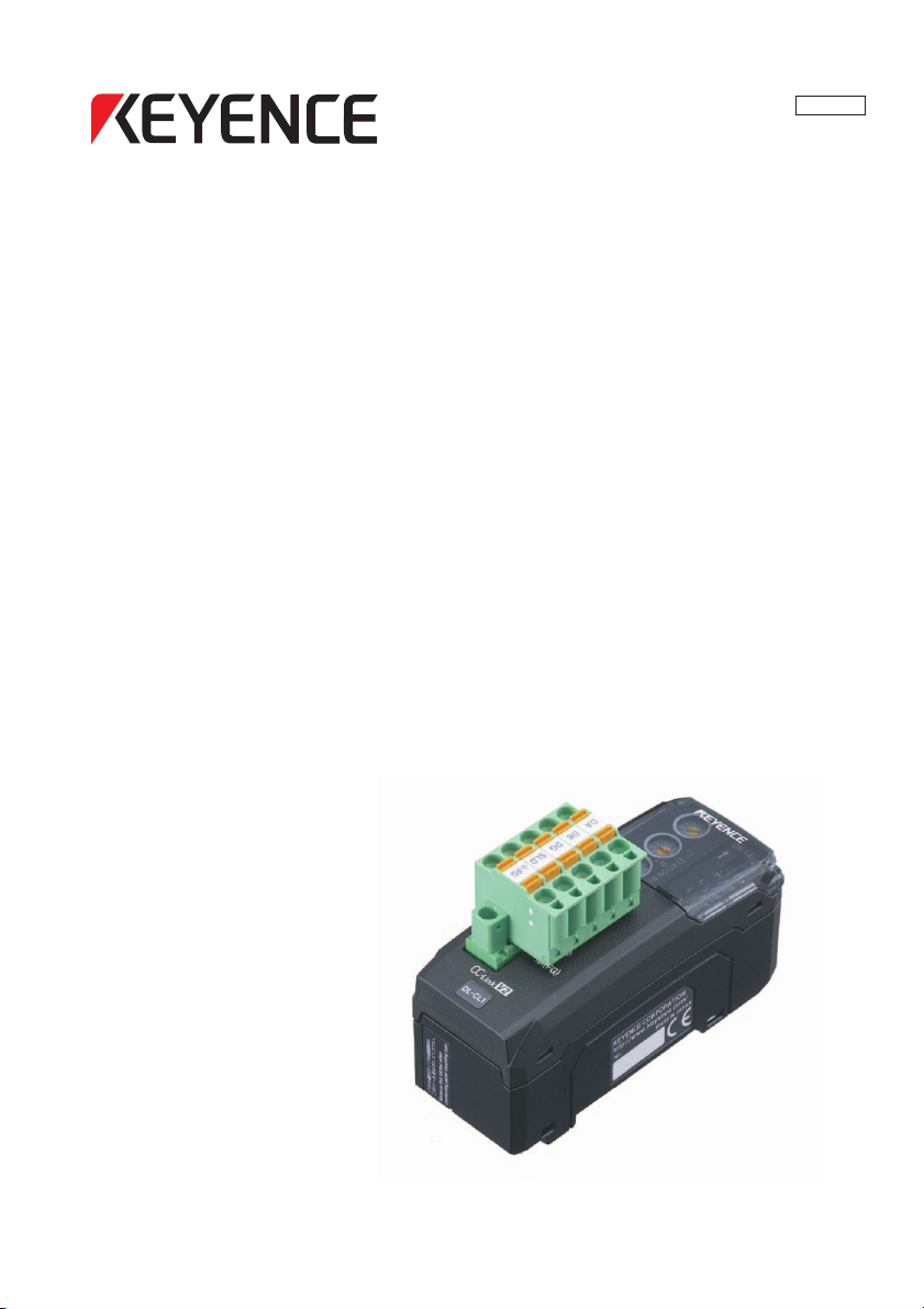
DL-CL1
User’s Manual (FD-S)
Read this manual before using the product in order to
achieve maximum performance.
Keep this manual in a safe place for future reference.
CC-Link Compatible Network Unit
Page 2
Introduction
This manual describes the basic operations and hardware functions of the DL-CL1. Read
the manual carefully to ensure safe performance and function of the DL-CL1.
Keep this manual in a safe place for future reference.
Ensure that the end user of this product receives this manual.
Symbols
The following symbols alert you to matters concerning the prevention of injury and product
damage.
It indicates cautions and limitations that must be followed during operation.
It indicates additional information on proper operation.
It indicates tips for better understanding or useful information.
The names of systems and products used in this manual are the trademarks or registered
trademarks of their respective owners.
It indicates a hazardous situation which, if not avoided, will result in
death or serious injury.
It indicates a hazardous situation which, if not avoided, could result
in death or serious injury.
It indicates a hazardous situation which, if not avoided, could result
in minor or moderate injury.
It indicates a situation which, if not avoided, could result in product
damage as well as property damage.
Point
Important
CAUTION
DANGER
NOTICE
WARNING
Reference
Page 3
Safety Precautions
CAUTION
NOTICE
General Precautions
• Before and while operating this product, confirm that it provides its functions
and performance correctly.
• Implement sufficient safety measures to prevent human and physical damages
in case this product fails.
• Be aware that the product functions and performance are not warranted if the
product is used outside the range of stated specifications or is modified by t
customer.
• Combining this product with other equipment requires sufficient consideration
because the proper functions and performance may not be provided depending
on the environment.
• Do not use this product in applications for human protection.
• Do not expose equipment, including peripherals, to rapid temperature changes.
Equipment failure may result from dew condensation.
Precautions for Use
• In the following cases, immediately turn off the power. Leaving
the equipment in unusual condition in may result in human
injury or equipment failure.
- Water or foreign matter entered the main unit;
-The case is broken, for example if it is dropped;
- Smoke or unusual smell comes out of the product.
• Use the correct power voltage. Failure to observe may result in
injury or failure.
• Do not disassembly or modify this product. Failure to observe
may result in injury.
he
Do not turn off the power while you are setting any item. Doing this
may cause loss of data settings wholly or partially.
96158E
1
Page 4

Equipment Environment
For safe, trouble-free operation of this product, the product must not be installed on
the following locations:
• Humid, dusty, or ill-ventilated.
• Exposed to direct sunlight or heating source.
• Exposed to corrosive or flammable gases.
• Exposed directly to vibration or shock.
• Exposed to water, oil, or chemical splashes.
• Exposed to static electricity.
Noise Protection
If this product is installed on a location near a noise source, e.g., power source or
high-voltage line, it may malfunction or fail because of noise. Use protection mea-
sures, such as using a noise filter or running the cords separately.
About Power Supply
• Noise superimposed on the power supply could cause malfunction. Use a stabilized DC power supply configured with an isolation transformer.
• When using a commercially available switching regulator, be sure to ground the
frame ground terminal or ground terminal.
Notes on Regulations and Standards
UL Certificate
This product is an UL/C-UL Listed product.
• UL File No. E207185
• Category NRAQ, NRAQ7
Be sure to consider the following specifications when using this product as an UL/CUL Listed Product.
• Use a power supply with Class 2 output defined in NFPA70 (NEC: National Electrical Code).
• For wiring to the CC-Link connector, use the AWG 12-24 copper wire with temperature rating 60
• Use this product under pollution degree 2
• This product is an open type device. Therefore, it must be installed in an enclosure
with IP 54 or higher. (e.g. Industrial control panel)
2
ο
C or more.
- CC-Link Compatible Network Unit DL-CL1 User’s Manual (FD-S) -
Page 5

CE Marking
Keyence Corporation has confirmed that this product complies with the essential
requirements of the applicable EC Directive, based on the following specifications.
Be sure to consider the following specifications when using this product in the Member State of European Union.
■ EMC Directive
EMI : EN55011, Class A
EMS : EN61000-6-2
• Install this product in a conductive enclosure. (e.g. Industrial control panel)
Remarks
These specifications do not give any guarantee that the end-product with this
product incorporated complies with the essential requirements of EMC Directive.
The manufacturer of the end-product is solely responsible for the compliance on
the end-product itself according to EMC Directive.
- CC-Link Compatible Network Unit DL-CL1 User’s Manual (FD-S) -
3
Page 6
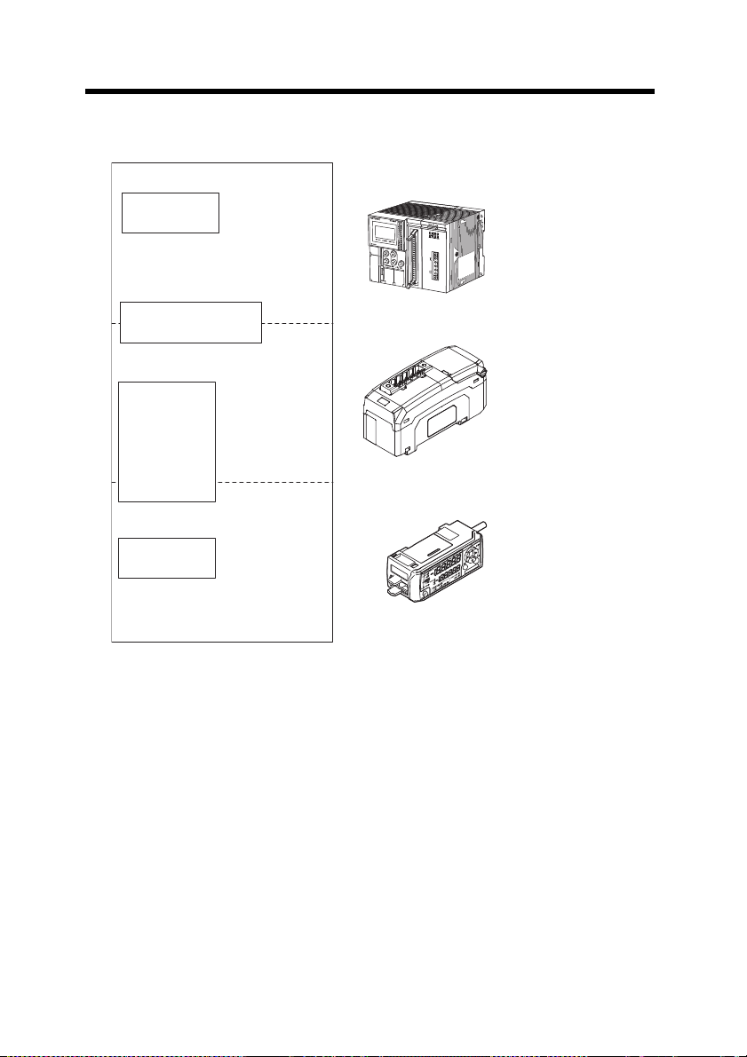
Relevant Manuals
Sensor amplifier
Manuals relevant
to CPU unit
Manuals relevant to
CC-Link master unit
Manuals of sensor
amplifier main unit
PLC CPU unit
CC-Link master unit
DL-CL1 (This unit)
This manual
Example:
・
FD-S series instruction manual
Example: KV-5000 user's manual
Example: KV-CL20 user's manual
The manuals to relevant to this document are as follow s:
4
- CC-Link Compatible Network Unit DL-CL1 User’s Manual (FD-S) -
Page 7

Manual Organization
This chapter provides an overview of the DL-CL1
and describes its part names and functions.
Before Using
1
This chapter explains the procedures for
connecting sensor amplifiers to the DL-CL1
and how to configure the data link.
Connection and
Configuration
2
This chapter describes the configuration of the
memory linked to the CC-Link master station and
provides communication time charts.
3
Provides the parameter list, as well as
troubleshooting instructions.
Appendix
5
This chapter describes the specifications
and dimensions of the DL-CL1.
Specifications
4
Communicating
with the FD-S
series
1
2
3
4
5
- CC-Link Compatible Network Unit DL-CL1 User’s Manual (FD-S) -
5
Page 8

Table of Contents
Safety Precautions.............................................................................1
General Precautions .......................................................................... 1
Precautions for Use ........................................................................... 1
Notes on Regulations and Standards ................................................ 2
Relevant Manuals...............................................................................4
Manual Organization..........................................................................5
Table of Contents............................................................................... 6
Ter ms Used in This Document ......................................................... 8
Chapter 1 Before Using
1-1 DL-CL1 Overview ............................................................................... 1-2
Overview......................................................................................... 1-2
Ty pe s and Number of Connectable Sens or Amplifiers ................... 1-2
1-2 Checking the Package Contents ...................................................... 1-3
Package Content............................................................................. 1-3
List of Optional Parts....................................................................... 1-3
1-3 Names and Functions of Each Part ................................................. 1-4
Chapter 2 Connection and Configuration
2-1 Installation and Connection to Sensor Amplifiers ......................... 2-2
ID Number Assignments to Sensor Amplifiers................................ 2-2
Installation and Connection to Sensor Amplifiers ........................... 2-3
2-2 Wiring.................................................................................................. 2-6
Connecting to the CC-Link System................................................. 2-6
2-3 Configuring the Data Link............................................................... 2-10
Configuring the Master Station ..................................................... 2-10
Configuring the DL-CL1 ................................................................ 2-10
Chapter 3 Communicating with the FD-S series
3-1 CC-Link Communication and Operating Modes ............................. 3-2
Data Exchanged by Cyclic Transfer ................................................ 3-2
Selecting an Operating Mode of the DL-CL1.................................. 3-3
3-2 Device Maps ....................................................................................... 3-4
Device Maps for Small-Memory Mode 1,
Small-Memory Mode 2, and Monitor Mode 1.................................. 3-4
Device Maps for Monitor Mode 2, Full Mode 1, and Full Mode 2.. 3-10
3-3 Communication Methods ................................................................ 3-17
Reading an Output from a Sensor Amplifier ................................. 3-17
6
- CC-Link Compatible Network Unit DL-CL1 User’s Manual (FD-S) -
Page 9

Table of Contents
Entering an External Input into a Sensor Amplifier....................... 3-17
Reading Current Valu es (Instantaneous Flow Rate)
from Sensor Amplifiers.................................................................. 3-18
Issuing a Motion Command to a Sensor Amplifier........................ 3-20
Rewriting a Setting Value of a Sensor Amplifier ........................... 3-21
Reading/Writing Settings or Status of a Sensor Amplifier ............ 3-21
3-4 Command Parameter List ............................................................... 3-24
Common Command Parameter List.............................................. 3-24
Command Parameter List for FD-S Series ................................... 3-25
Chapter 4 Specifications
4-1 Specifications .................................................................................... 4-2
4-2 Data Processing Times ..................................................................... 4-3
4-3 Dimensions ........................................................................................ 4-4
Chapter 5 Appendix
5-1 Troubleshooting................................................................................. 5-2
5-2 Index ................................................................................................... 5-5
- CC-Link Compatible Network Unit DL-CL1 User’s Manual (FD-S) -
7
Page 10

Terms Used in This Document
This document uses the following terms:
Ter m Description
Sensor A sensor amplifier.
Main unit A sensor amplifier that has a power line and can operate alone.
Expansion unit
D-bus
A sensor amplifier that does not have a power line and must be
connected to a main unit.
The name of KEYENCE's wiring-saving system for sensor amplifi-
ers.
Supports FD-S Series colioris t
ype digital flow sensors and others.
8
- CC-Link Compatible Network Unit DL-CL1 User’s Manual (FD-S) -
Page 11

Before Using
This chapter provides an overview of the DL-CL1 and describes its
part names and functions.
1-1 DL-CL1 Overview ............................................... 1-2
1-2 Checking the Package Contents ........................ 1-3
1-3 Names and Functions of Each Part....................1-4
1
- CC-Link Compatible Network Unit DL-CL1 User’s Manual (FD-S) -
1-1
Page 12
1-1
DL-CL1 Overview
1
Overview
Before Using
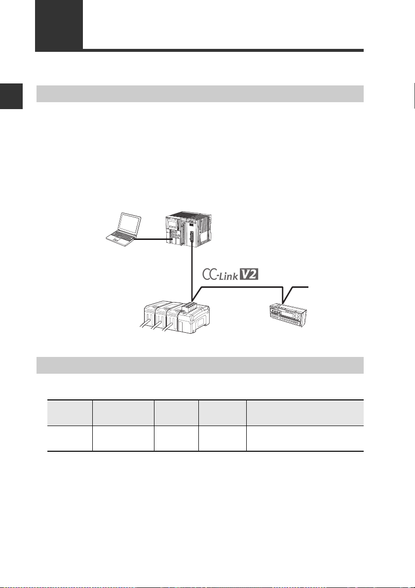
This unit operates as a remote device station (Ver. 1.1 and 2 switchable) of a CC-Link
system. Using CC-Link communications, the sensor amplifiers and other units connected to the DL-CL1 can transmit their ON/OFF control signals and current values as
communication data to PLC or other equipment.
The DL-CL1 supports cyclic transfer and extended cyclic transfe r, enabli
cation without the need of a ladder program. In addition, remote input/output sig-
muni
nals can be used as handshake signals to read/write settings of sensor amplifiers and
to execute motion commands on the sensor amplifiers.
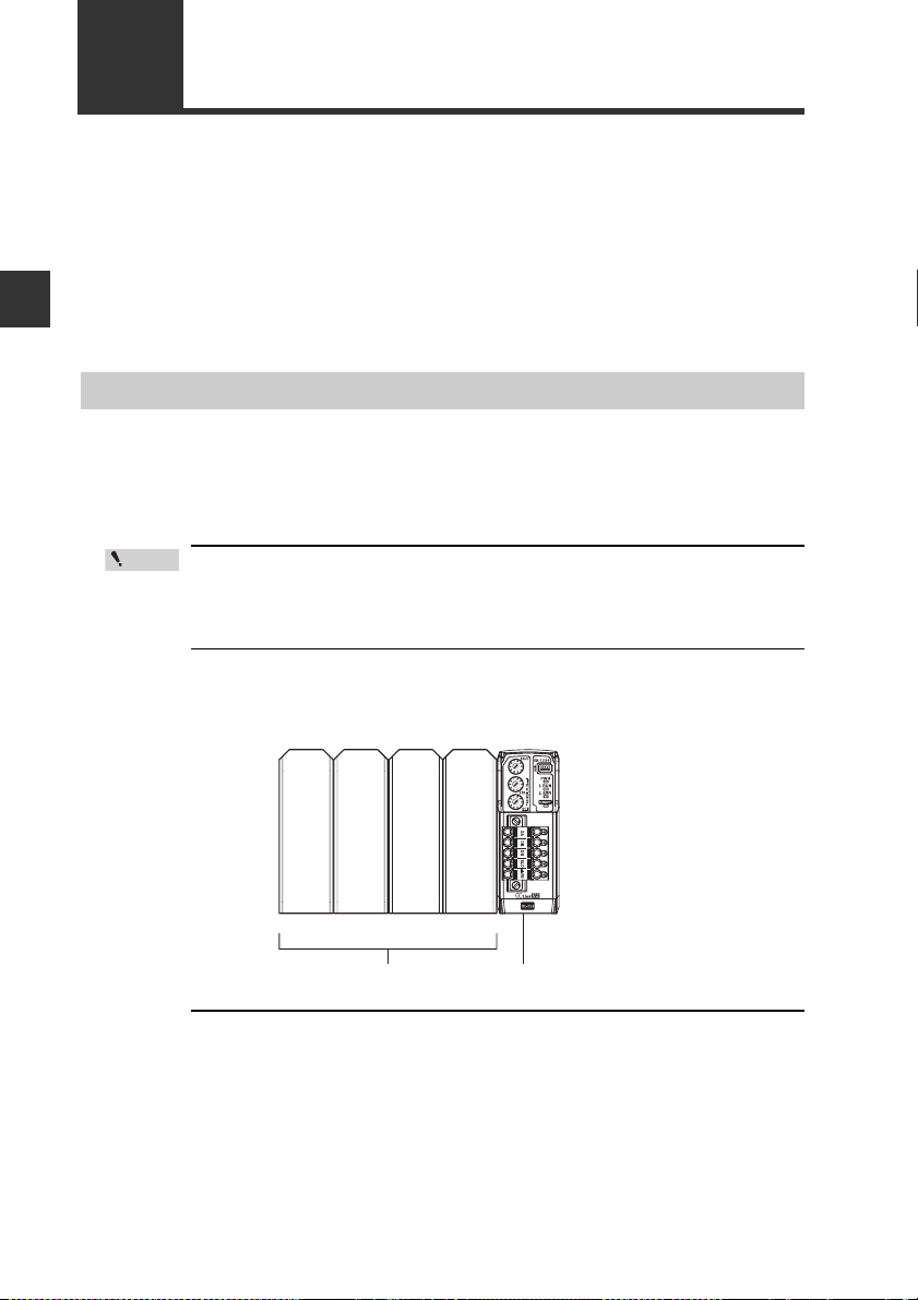
System configuration example
Type s and Number of Connectable Sensor Amplifiers
DL-CL1 (This unit)
D-bus compatible sensor amplifier
PLC or other host device
(CC-Link master unit)
ng data com-
CC-Link slave
Number of Connectable Sensor Amplifiers
Name Amplifier form Main unit
FD-S
Series*
*Cannot be connected to a pane
The DL-CL1 can connect multiple sensor amplifiers (a single main unit and multiple
expansion units) which support D-Bus. "D-bus" is the name of KEYENCE's wiringsaving system for sensor amplifiers.
Different types of sensor amplifiers with D-bus support can be connected to the single
DL-CL1 unit.
How many and what different types of sensor
on the sensor amplifiers or units to be connected. Please inquire for details.
1-2
DIN rail
mounting type
- CC-Link Compatible Network Unit DL-CL1 User’s Manual (FD-S) -
FD-SA1NA
FD-SA1PA
Expansion
unit
FD-SA2NA
FD-SA2PA4(1 main unit, 3 expansion units)
l mounting type.
amplifiers
Maximum number of
connectable units
can be connected depends
Page 13
1-2
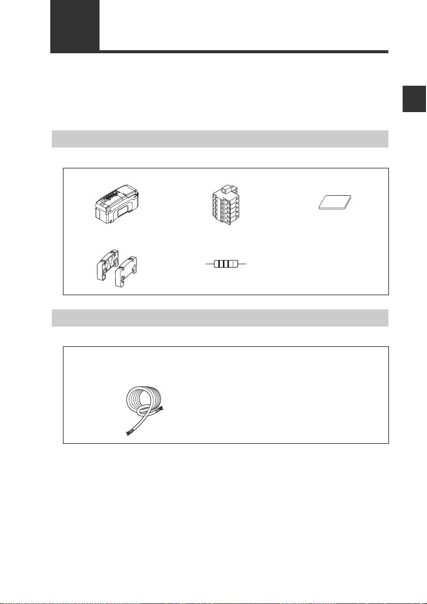
Before using the DL-CL1, make sure that the following equipment and accessories
are included in the package.
We have thoroughly inspected the package contents before shipment. However, in the
event of defective or broken items, contact your nearest KEYENCE office.
Checking the Package Contents
Package Content
DL-CL1 main unit x 1 CC-Link connector x 1 Expansion connector
sticker x 1
1
Before Using
End unit x 2 Resistor
110Ω 1/2W
(brown/brown/brown/gold)
List of Optional Parts
OP-79426 (CC-Link Ver. 1.10 compatible cable, 20 m)
OP-79427 (CC-Link Ver. 1.10 compatible cable, 100 m)
Cable x 1
Instruction manual x 1
- CC-Link Compatible Network Unit DL-CL1 User’s Manual (FD-S) -
1-3
Page 14
1
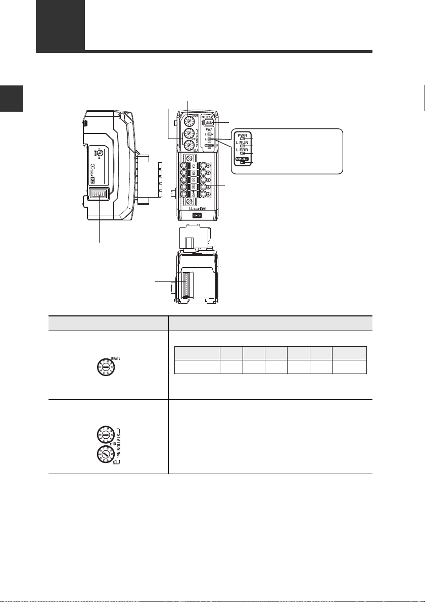
(5)
Communication indicator (green)
(6) Communication error indicator (red)
(7) Sensor communication indicator
(red/green)
(4) Power indicator (green)
(9) Sensor amplifier connector
(for DIN rail mounting type)
(8) CC-Link connector
(1) Transmission rate setting switch
(3) Operating mode setting switch
(2) Station number setting switch
(10) Sensor amplifier connector
(for panel mounting type
and large display type)
DL
CL1
20-30V DC, Class2
15JN
IND.CONT.EQ.
No.
0 1 2 3 4 5 to 9
Transmission rate
(bps)
156k 625k 2.5M 5M 10M
Cannot be set
1-3
Names and Functions of Each Part
This section describes the part names and functions of the DL-CL1.
Before Using
Name Description
(1) Transmission rate setting
Sets the transmission rate of CC-Link.
switch
(2) Station number setting
switch
1-4
Default value: 0
Sets the station number of the DL-CL1 in the CCLink.
x10: Ten's digit
x1: One's digit
Setting range: 01 to 64
Default value: 01
- CC-Link Compatible Network Unit DL-CL1 User’s Manual (FD-S) -
Page 15
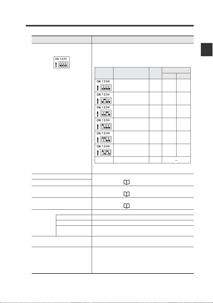
Name Description
Switch setting
Operating mode
Station
configuration
Number of link points
RX/R Y
RW w/ RW r
Small-memory mode 1
(1-output, 1-input)
1-station, 1x
32
4
Small-memory mode 2
(3-output, 3-input)
64
8
Monitor mode 1
(5-output, 5-input, current value,
BANK change)
128
16
128
32
Full mode 1
(5-output, 5-input, current value,
BANK change, setting value change)
384
64
Others Cannot be set −
224
32
2-station, 1x
4-station, 1x
1-station, 8x
4-station, 2x
2-station, 8x
Monitor mode 2
(5-output, 5-input, current value,
BANK change)
Full mode 2
(5-output, 5-input, current value,
BANK change, setting value change)
(3) Operating mode setting
switch
1-3 Names and Functions of Each Part
Sets the operating mode of the DL-CL1 in the CCLink. The specific data that can be communicated
using cyclic transfer varies with each operating
mode.
1
Before Using
(4) Power indicator When normal: Lit in green
(5) Communication indicator
(6) Communication error
indicator
(7) Sensor communication
indicator
(8) CC-Link connector Attach the CC-Link cable to this connector.
(9) Sensor amplifier connec-
tor (for DIN rail mounting)
(10)Sensor amplifier
connector
(for panel mounting/large
display)*
* Not used with the FD-S series.
- CC-Link Compatible Network Unit DL-CL1 User’s Manual (FD-S) -
Default value: Small-memory mode 1
For details, see "Troubleshooting" (page 5-2).
When normal: Not lit
For details, see "Troubleshooting" (page 5-2).
When normal: Lit in green
DA/DB/DG Communication signal
SLD Connect the shielded wire of the CC-Link cable.
For details, see "Troubleshooting" (page 5-2).
FG Ground this functional ground terminal.
(Ground resistance: 100 ohm or less)
Attach the sensor amplifier to this connector.
Attach the sensor amplifier to this connector.
When shipped from the factory, a protective sticker
is installed.
The optional expansion cable (OP-35361) is used
for this connection.
1-5
Page 16

1
1-3 Names and Functions of Each Part
MEMO
Before Using
1-6
- CC-Link Compatible Network Unit DL-CL1 User’s Manual (FD-S) -
Page 17

Connection and Configuration
This chapter explains the procedures for connecting sensor
amplifiers to the DL-CL1 and how to configure the data link.
2-1 Installation and Connection to Sensor Amplifiers
........................................................................... 2-2
2-2 Wiring ................................................................. 2-6
2-3 Configuring the Data Link.................................2-10
2
- CC-Link Compatible Network Unit DL-CL1 User’s Manual (FD-S) -
2-1
Page 18
2
Point
ID number
01
Main unit
Expansion unit Expansion unit Expansion unit
02
...
04
Sensor amplifier DL-CL1
2-1
This section provides the procedures for installing the DL-CL1 and connecting to
sensor amplifiers.
The DL-CL1 can be connected with the expansion units of sensor amplifiers which
support D-bus. ("D-bus" is the name of KEYENCE's wiring-saving system for sensor
amplifiers.) How many sensor amplifiers can be connected depends on the sensor
amplifiers or units to be connected. For specif
Connection and Configuration
manual of each sensor amplifier.
Installation and Connection to Sensor Amplifiers
ic numbers of connections, refer to the
ID Number Assignments to Sensor Amplifiers
When connecting the DL-CL1 to a sensor amplifier which can be configured with
expansion units, the main unit will be assigned ID number 01, with the expansion units
assigned ID numbers of 02 to 04.
• The ID number assignments to sensor amplifiers cannot be
changed by the user.
• In this manual, ID number 01 to ID number 04 are denoted as ID 01
to ID 04, respectively.
- CC-Link Compatible Network Unit DL-CL1 User’s Manual (FD-S) -
2-2
Page 19

2-1 Installation and Connection to Sensor Amplifiers
(1)
(2)
(3)
Installation and Connection to Sensor Amplifiers
Mounting on a DIN rail
Align the claw on the bottom of the amplifier with the DIN rail. While push-
1
ing the amplifier in the direction of arrow (1), press down in the direction
of arrow (2).
To remove the DL-CL1, raise the main unit in the direction of arrow (3)
2
while pushing it the direction of arrow (1).
2
Connection and Configuration
- CC-Link Compatible Network Unit DL-CL1 User’s Manual (FD-S) -
2-3
Page 20
2
Point
2-1 Installation and Connection to Sensor Amplifiers
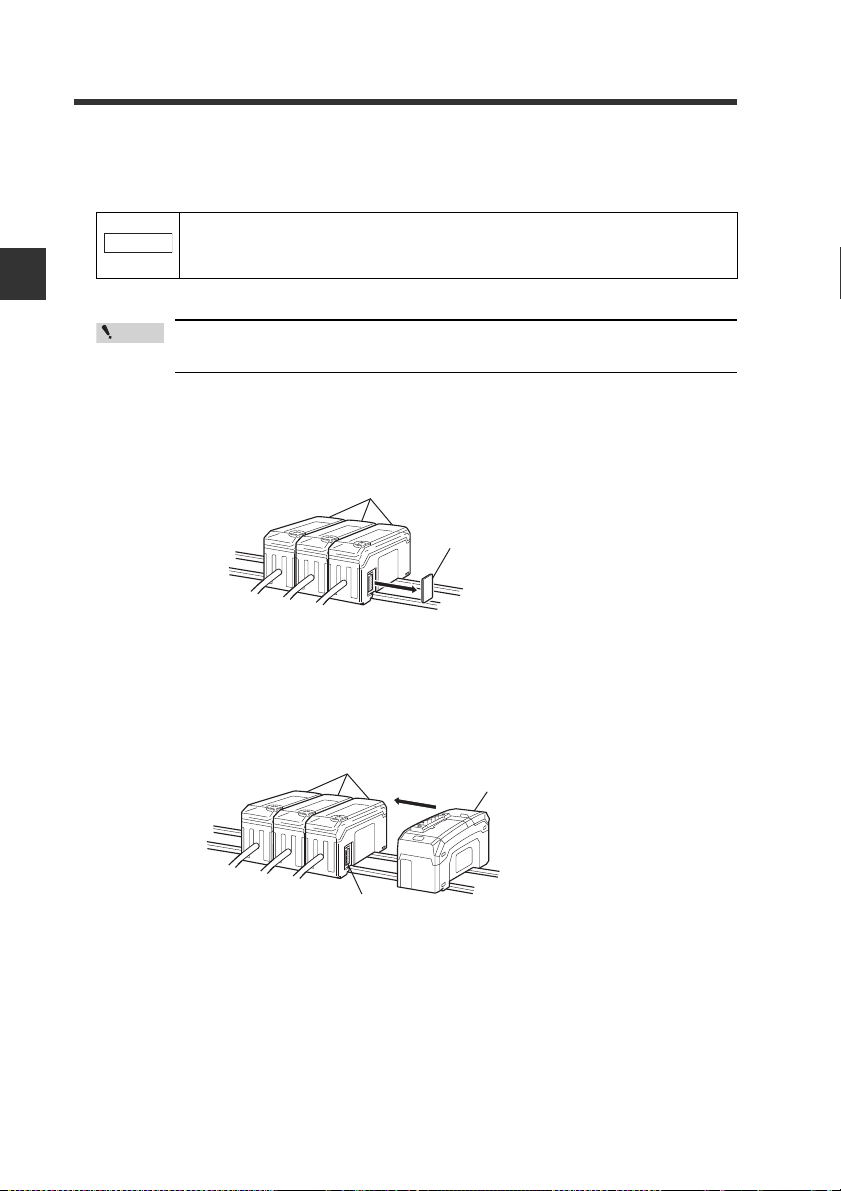
Procedures for connecting to sensor amplifiers
The CC-Link compa tible communication unit DL-CL1 must be connected to sensor
amplifiers before it can provide its function.
Make sure that the power to the sensor amplifier is off before starting to
NOTICE
connect the CC-Link compatible communication unit DL-CL1. Performing the procedure with the power on may damage the DL-CL1.
Connection and Configuration
1
2
For the instructions on connecting additional sensor amplifiers, refer
to the instruction manual of the sensors amplifiers.
Remove the expansion protective cover from the sensor amplifier to be
connected.
Sensor amplifier
Expansion protective cover
Install the CC-Link compatible communication unit DL-CL1 on the DIN rail
and connect to the sensor amplifier.
Ensure a tight connection, leaving no space between the CC-Link compatible
communication unit DL-CL1 and the sensor amplifier.
Sensor amplifier
CC-Link compatible
communication unit DL-CL1
2-4
Connector
- CC-Link Compatible Network Unit DL-CL1 User’s Manual (FD-S) -
Page 21

2-1 Installation and Connection to Sensor Amplifiers
Make sure that the sensor amplifier connector (for DIN rail mounting
type) is not askew on the side face of the CC-Link compatible communication unit DL-CL1, as shown below. If the connector is askew, the DL-
CL1 may become damaged when connected to the sensor amplifier.
Sensor amplifier connector
NOTICE
CC-Link compatible
communication unit DL-CL1
Mount the supplied end units (OP-26751: a set of two pieces) on the outer
3
side faces of the amplifier and the CC-Link compatible communication
unit DL-CL1. Then, fix the end units with the screws on the top of each
end unit (2 points x 2 units). (Tightening torque: 0.6 N•m or less)
Mount the end units in the same way as the CC-Link compatible communication
unit DL-CL1.
End unit
2
Connection and Configuration
NOTICE
End unit
Press the CC-Link compatible communication unit DL-CL1 into full
engagement with the sensor amplifier. If the DL-CL1 is connected in
slant position or not pressed fully, it may be damaged when the power is
turned on.
- CC-Link Compatible Network Unit DL-CL1 User’s Manual (FD-S) -
2-5
Page 22
2
Point
Point
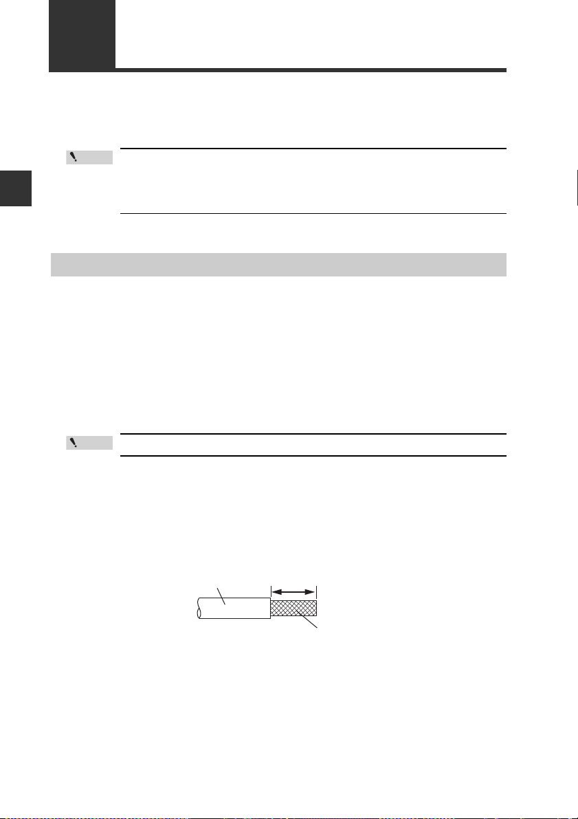
Sheath
Shield braid
Approx. 50 mm
2-2
Connection and Configuration
Connecting to the CC-Link System
Usable cables
Wiring
This section describes how to wire the DL-CL1.
• Turn off the power before starting the cabling operation.
• For more information about the CC-Link system, including cable
length and cabling methods, refer to the document of the CC-Link
master unit.
Use the following procedures to connect the DL-CL1 to the CC-Link system.
For connection between the DL-CL1 and the CC-Link system, use CC-Link cables
(Ver. 1.10 or later) accredited by the CC-Link Partner Association.
CC-Link cables (for Ver. 1.10) are available as optional items.
OP-79426 (20 m) OP-79427 (100 m)
To e nsure normal communication, only use the CC-Link cables.
Trimming the cable
1
2-6
Strip the cable sheath.
Strip approximately 50 mm of the sheath from the end of the CC-Link cable,
with care to avoid damaging the shield braid of the cable.
- CC-Link Compatible Network Unit DL-CL1 User’s Manual (FD-S) -
Page 23
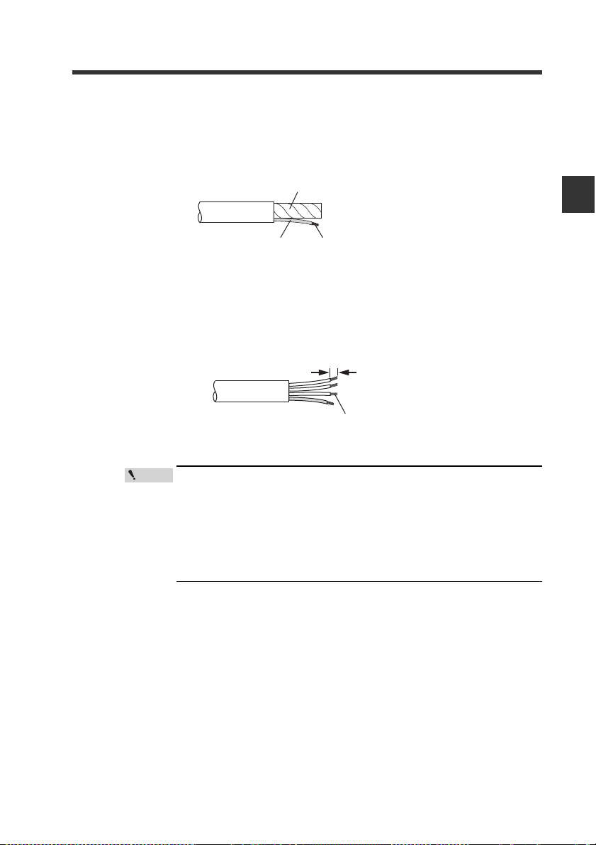
Tri m the shield.
Aluminum polyester laminated tape
Insulating tube
Shield braid twisted together
Twist together the conductors
Approx. 10 mm
2
Upbraid the shield braid carefully. Find the bare drain wire (twisted or flying)
inside the shield braid. Twist together the unbranded shield braid and the drain
wire securely, and then put on the insulating tube.
Strip the sheathed conductors.
3
Strip approximately 10 mm of sheath from each signal wire, by removing the
aluminum polyester laminated tape. Take care not to damage the signal wires.
Tw ist together the exposed conductors securely.
2-2 Wiring
2
Connection and Configuration
Point
- CC-Link Compatible Network Unit DL-CL1 User’s Manual (FD-S) -
• If you are using solderless terminals, perform cable wiring/
trimming appropriately to suit the specifications of the particular terminals.
Recommended solderless terminals: Phoenix Contact's A/AI
Series
• Do not perform soldering (pre-soldering) on the trimmed end
of the cable.
2-7
Page 24

2
Terminal name
Function
DA/DB/DG
Communication signal
SLD Connect the shielded wire of the CC-Link cable.
FG
Ground this functional ground terminal. (Ground resistance: 100 ohm or less)
2-2 Wiring
Connecting the cable
Use the following procedures to connect to the CC-Link connector supplied with the
DL-CL1.
Connect the trimmed cable to the CC-Link connector.
1
Insert the cable completely.
Connection and Configuration
Attach the CC-Link connector to the DL-CL1.
2
Plug the connector into the DL-CL1 and screw it down with the screws on each
end.
(Tightening torque: 0.2 to 0.3 N•m)
2-8
- CC-Link Compatible Network Unit DL-CL1 User’s Manual (FD-S) -
Page 25

2-2 Wiring
Connecting the termination resistor
If the DL-CL1 is at the end of the CC-Link system, connect the supplied termination
resistor to DA/DB of the CC-Link connector.
Type of cable Termination resistor
CC-Link Ver. 1.10 compatible cable 110Ω, 1/2 W (brown/brown/
brown/gold)
2
Connection and Configuration
- CC-Link Compatible Network Unit DL-CL1 User’s Manual (FD-S) -
2-9
Page 26

2
Point
Reference
Reference
Operating mode setting switch
Transmission rate
setting switch
Station number
setting switch
2-3
Use the following configuration procedures for connecting the DL-CL1 to the CC-Link
system.
Connection and Configuration
Configuring the Master Station
To connect the DL-CL1 to the CC-Link master unit, it is necessary to configure the
slave attribute and memory allocation settings.
Slave attribute settings
Register the DL-CL1 to the CC-Link master unit as a remote device station.
Yo u can also configure the settings by importing a CSP file into the software for the
master unit (ladder programming software or CC-Link configuration software).
Configuring the Data Link
This manual covers only the functions and settings of a CC-Link mas-
ter station which are required for communication with the DL-CL1. For
the functions and settings related to the communication between the
CC-Link master unit and CPU unit, refer to the manuals shipped with
your master unit or CPU unit.
Memory allocation settings
Configuring the DL-CL1
2-10
The CSP file can be downloaded from the KEYENCE web site
http
://www.keyence.com
In order to exchange data between the DL-CL1 and CC-Link master station, configure
the memory allocation settings using the software for the master station (ladder
programming software or CC-Link configuration software).
Where multiple slave units are connected, the memory allocation for each
slave unit is done automatically based on the spe
The allocation information for each slave unit can be checked using the
CC-Link configuration software.
Use the following procedures to configure the data link of the DL-CL1.
- CC-Link Compatible Network Unit DL-CL1 User’s Manual (FD-S) -
ied starting address.
cif
:
Page 27

2-3 Configuring the Data Link
Setting the transmission rate
Set the transmission rate of the DL-CL1 to the same value as set in the CC-Link
master station.
Do this using the transmission rate setting switch on the DL-CL1.
• Default value: 0
No. 0 1 2 3 4 5 to 9
Tr ansmission rate (bps) 156 k 625 k 2.5 M 5 M 10 M
Cannot be set.
Setting the station number
Using the station address setting switch, set the station number (slave ID) assigned to
the DL-CL1.
• Default value: 01
e: 0
• Setting rang
1 to 64
Selecting an operating mode
Using the operating mode setting switch, set the combination of the number of
stations occupied by the DL-CL1 and the extended cyclic setting. The specific data
that can be communicated using cyclic transfer varies with each operating mode.
See the section "Selecting an Operating Mode of the DL-CL1" and select the
appropriate operating mode that suits the desired function of sensor amplifiers.
• Default
value: Small-memory mode 1
• The contents of output and current value vary depending on the sensor amplifiers
to be connected.
Examples: 3-level judgment output for 3-output mode; 5-level judgment output for
5-output mode. Current value: judgment value.
Number of link points
Switch setting
Others Cannot be set −
Operating mode
Small-memory mode 1
(1-output, 1-input)
Small-memory mode 2
(3-output, 3-input)
Monitor mode 1
(5-output, 5-input, current value,
BANK change)
Monitor mode 2
(5-output, 5-input, current value,
BANK change)
Full mode 1
(5-output, 5-input, current value,
BANK change, setting value change)
Full mode 2
(5-output, 5-input, current value,
BANK change, setting value change)
Station
configuration
1-station, 1x
2-station, 1x
4-station, 1x
1-station, 8x
4-station, 2x
2-station, 8x
RX/R Y
32
64
128
128
224
384
RW w/ RW r
4
8
16
32
32
64
2
Connection and Configuration
- CC-Link Compatible Network Unit DL-CL1 User’s Manual (FD-S) -
2-11
Page 28

2
Point
2-3 Configuring the Data Link
Each switch should be set before turning on the power. If any setting
is changed while the DL-CL1 is operating, the new setting will not be
applied until the power is turned on again. (The communication error
indicator flashes intermittently.)
Connection and Configuration
2-12
- CC-Link Compatible Network Unit DL-CL1 User’s Manual (FD-S) -
Page 29

Communicating with the FD-S series
This chapter describes the configuration of the memory linked to the
CC-Link master station and provides communication time charts.
3-1 CC-Link Communication and Operating Modes.3-2
3-2 Device Maps....................................................... 3-4
3-3 Communication Methods.................................. 3-17
3-4 Command Parameter List................................. 3-24
3
- CC-Link Compatible Network Unit DL-CL1 User’s Manual (FD-S) -
3-1
Page 30

3
3-1
CC-Link Communication and Operating Modes
The DL-CL1 operates as a remote device station of a CC-Link system.
This section describes the data that the DL-CL1 can exchange through the CC-Link,
and available operating modes.
Data Exchanged by Cyclic Transfer
The DL-CL1's data is linked with the CC-Link maser station as shown below.
Sensor amplifier
Communicating with the FD-S series
CC-Link master station DL-CL1
(1) RX (Remote inputs)
RWr (Remote registers)
(3)
Output
Current value
Error information
Read parameter
(2) RY (Remote inputs)
RWw (Remote registers)
(4)
Request to change setting value
Changed setting value
External input
Write parameter
Output
Current value
・・・・・・
・・・・・・
Error information
・・・・・・
・・・・・・
Setting value
External input
・・・・・・
Output
Current value
・・・・・・
・・・・・・
Errror information
・・・・・・
・・・・・・
・・・・・・
設定値
外部
・・・・・・
Output
Current value
・・・・・・
・・・・・・
Errror information
・・・・・・
・・・・・・
設定値
外部
・・・・・・
Read/write parameters
Through the link, the CC-Link master station is enabled to:
• Communicate the output signal, current value, an
d error status of sensor amplifiers
without the need of a ladder program.
• Use the remote input RX and remote output RY areas as handshake signals to
execute external inputs to, or change the setting values of, sensor amplifiers.
• Execute motion commands on sensor amplifiers.
• Directly read and write the parameters of sensor amplifiers. This capability gives
the ability to use functions that can be executed on sensor amplifiers.
3-2
- CC-Link Compatible Network Unit DL-CL1 User’s Manual (FD-S) -
Page 31

3-1 CC-Link Communication and Operating Modes
Selecting an Operating Mode of the DL-CL1
Select an operating mode of the DL-CL1 to suit the functions of the sensor amplifiers
to be used.
The specific CC-Link device configuration and the data that can be communicated
using cyclic transfer vary with each operating mode of the DL-CL1. An appropriate
operating mode should be determined by considering the number of link points the
data that can be communicated.
"Configuring the Data Link" (page 2-
Method of
communication
with the master
station
Remote input RX Read out-
Remote register RWr Read current value
Remote output RY External
Remote register
RWw
Handshake co ntrol
*3
program
(Command
communication)
Available function
of sensor
amplifier
puts 1 - 5
(instantaneous fl ow
*4
rate)
inputs 1-5
Rewrite setting
*4
value
Motion command No No Yes Ye s Ye s Ye s 3-20
Read output
Read current value
Read setting/status
Write setting/status
Small-
memory
mode 1
*1
1-station, 1x2-station, 1x4-station, 1x1-station, 8x4-station, 2x2-station,
Output 1
Ye s Ye s Ye s Ye s Ye s Ye s 3-4
Output 2
Output 3
Unused
Unused
Integration
Ye s Ye s Ye s Ye s Ye s Ye s
reset
Flow rate
hold reset
Zero
adjust-
ment
Te m p e r a-
ture hol d
reset
Unused
10)
Operating mode of DL-CL1
Small-
Monitor
mode 1
Ye s
Monitor
mode 2
*2
memory
mode 2
p. 3-4 p. 3-10
No Yes Ye s Ye s Ye s Ye s
No Yes Ye s Ye s Ye s Ye s
------
------
No No
No Yes Ye s Ye s Ye s Ye s
No Yes Ye s Ye s Ye s Ye s
No No Yes Ye s Ye s Ye s
------
No No No No Yes Ye s
No No Yes Ye s Ye s Ye s
Full
mode 1
Ye s Ye s Ye s
Full
mode 2
8x
Reference
page for
communica tion
method
3-6
3-12
3-16
3-17
3
Communicating with the FD-S series
Ye s: Available with sensor amplifiers of ID 01 to 04. No: Not available.
*1 For details of the functions assigned for motions commands and setting/status read/write, see
"Device Maps" (page 3-4) and "Command Parameter List" (page 3-24).
*2 In remote register RWw, specify the ID number of the sensor amplifier from which to read.
*3 To use this communication method, create a program that controls
commands by handshaking
between a remote input/output and remote register.
*4 It is possible to read instantaneous flow rate or rewrite setting value regardless of the detection
mode setting.
- CC-Link Compatible Network Unit DL-CL1 User’s Manual (FD-S) -
3-3
Page 32

3
Operating
mode
Device no.
(HEX)
Name
Communication
method
Description Reading range
Small-memory mode 1
Small-memory mode 2
Monitor mode 1
RX[n] + 00
to 03
Output-1 ID 01
to ID 04
*1
Sends the output-1 state (ON/OFF) of the
sensor amplifi er.
The output-1 of each sensor amplifi er (ID 01
to ID 04) corresponds to each RX.
0: OFF
1: ON
RX[n] + 0F Error state -
The DL-CL1 is not communicating properly
with the sensor amplifi er, or an error exists
with the sensor amplifi er.
If an error exists, the error code is stored in
error code (RWr[n] + 00).
0:No Error
1:Error
RX[n] + 10
to 13
Output-2 ID 01
to ID 04
*1
Sends the output-2 state (ON/OFF) of the
sensor amplifi er.
The output-2 of each sensor amplifi er (ID 01
to ID 04) corresponds to each RX.
0: OFF
1: ON
RX[n] + 1F (Not used) - - -
RX[n] + 20
to 23
Output-3 ID 01
to ID 04
*1
Sends the output-3 state (ON/OFF) of the
sensor amplifi er.
The output-3 of each sensor amplifi er (ID 01
to ID 04) corresponds to each RX.
0: OFF
1: ON
RX[n] + 2F System reserved - Unusable
RX[n] + 30
to 33
(Not used) - - -
RX[n] + 3F System reser
ved
- Unusable
RX[n] + 40
to 43
(Not used) - - -
RX[n] + 4F System reserved - Unusable
RX[n] + 50 Sensor ready *3
Used when communicating under handshake
control program.
This is output when command execution is
ready.
0: In preparation
1: Ready
RX[n] + 51
Command
complete
*3
Used when communicating under handshake
control program.
This is output when command execution is
complete.
0->1: Execution
complete
RX[n] + 52 Command error *3
Used when communicating under handshake
control program.
This is output when an error occurs during
command execution.
0:No Error
1:Error
3-2
Device Maps
The device maps vary as described in "Selecting an Operating Mode of the DL-
CL1" (page 3-3). Select an operating mode suited for the functions of the sensor
amplifiers to be used, before accessing each device.
Device Maps for Small-Memory Mode 1, Small-Memory Mode 2, and Monitor Mode 1
The following device maps are used for when the operating mode is small-memory
mode 1, small-memory mode 2, or monitor mode 1.
In cases of monitor mode 2, full mode 1, and full mode 2, see "Device Maps for
Monitor Mode 2, Full Mode 1, and Full Mode 2" (page 3-10).
Communicating with the FD-S series
Remote Input RX (DL-CL1 -> Master Station)
3-4
- CC-Link Compatible Network Unit DL-CL1 User’s Manual (FD-S) -
Page 33

3-2 Device Maps
Operating
mode
Device no.
(HEX)
Name
Communication
method
Description Reading range
Monitor mode 1
RX[n] + 53
Current
Value Update
Locked
-
This is output when current value update is
locked (current value update lock request (RY[n]
+ 53) is enabled).
0: Update
enabled
1: Update
locked
RX[n] + 54
to 5D
System
reserved
- Unusable
RX[n] + 5E
Current value
page change
complete
*2
Used for reading the current value.This is output
when the current value page has been changed.
0->1: Change
complete
RX[n] + 5F
Current value
page change
error
*2
Used for reading the current value.This is output
if an error occurs while changing the current
value page.
0:No Error
1:Error
RX[n] + 60
to 63
(Not used) - - -
RX[n] + 6F (Not used) - - RX[n] + 1B
Remote ready -
This is output when the DL-CL1 is correctly
connected to the CC-Link system.
1: Proper communication is provided.Data from
the sensor amplifi er will be updated.
0: Proper communication is not provided.Data
from the sensor amplifi er will not be updated.
0: In preparation
1: Ready
RX[n] + 3B
RX[n] + 7B
Number [n] denotes the first relay number assigned to the DL-CL1.
*1 See "Reading an Output from a Sensor Amplifier" (page 3-17).
*2 See "Reading Current Values (Instantaneous Flow Rate) from Sensor Amplifiers" (page 3-18).
*3 See "Reading/Writing Settings or Status of a Sensor Amplifier" (page 3-21).
See "Issuing a Motion Command to a Sensor Amplifier" (page 3-20).
Remote Output RY (Master Station -> DL-CL1)
3
Communicating with the FD-S series
Operating
Small-memory mode 1
Device no.
mode
(HEX)
Small-memory mode 2
Monitor mode 1
RY[n] + 00
to 03
RY[n] + 0F System reserved - Unusable
RY[n] + 10
to 13
RY[n] + 1F System reserved - Unusable
RY[n] + 20
to 23
RX[n] + 2F System reserved - Unusable
RY[n] + 30
to 33
RX[n] + 3F System reserved - Unusab
Name
Integration reset
input
ID 01 to ID 04
Flow rate hold
reset input
ID 01 to ID 04
Zero adjustment
input
ID 01 to ID 04
Temperature
hold reset input
ID 01 to ID 04
- CC-Link Compatible Network Unit DL-CL1 User’s Manual (FD-S) -
Communication
method
Receives integration reset input by assigning
*1
each sensor amplifi er (ID 01 to ID 04) to each
RY.
Receives fl ow rate hold reset input by
*1
assigning each sensor amplifi er (ID 01 to ID
04) to each RY.
Receives zero adjustment input by assigning
*1
each sensor amplifi er (ID 01 to ID 04) to each
RY.
Receives temperature hold reset input by
*1
assigning each sensor amplifi er (ID 01 to ID
04) to each RY.
Description Writing range
le
0: OFF
1: ON
0: OFF
1: ON
0: OFF
1: ON
0: OFF
1: ON
3-5
Page 34

3
Operating
mode
Device no.
(HEX)
Name
Communication
method
Description Writing range
Monitor mode 1
RY[n] + 40
to 43
(Not used) - - -
RY[n] + 4F
to 50
System reserved - Unusable
RY[n] + 51
Request for
command
*3
Used when communicating under handshake
control program.
This is input when requesting command
execution.
0->1: Request
execution
RY[n] + 52 System reserved - Unusable
RY[n] + 53
Current Value
Update Request
-
Used to lock data update in current value
boxes (RWr[n] + 08 to 0D).
This may be used to obtain the current values
of multiple sensor amplifi ers at the same
timing.
The comparator value is locked while the
update request is held.
The update lock state can be checked by the
current value update lock state (RX[n] + 53).
0: Do not lock
update
1: Request
update lock
RY[n] + 54
to 5D
System reserved - Unusable
RY[n] + 5E
Request to
change current
value page
*2
Used for reading the current value.
This is input when requesting to change the
current value page (the ID number of the
sensor amplifi er to read from).
0->1: Request
change
R
Y[n] + 5F System reserved - Unusable
RY[n] + 60
to 63
(Not used) - - -
RY[n] + 6F (Not used) - - -
3-2 Device Maps
Communicating with the FD-S series
Number [n] denotes the first relay number assigned to the DL-CL1.
*1 See "Entering an External Input into a Sensor Amplifier" (page 3-17).
*2 See "Reading Current Values (Instantaneous Flow Rate) from Sensor Amplifiers" (page 3-18).
*3 See "Reading/Writing Settings or Status of a Sensor Amplifier" (page 3-21).
See "Issuing a Motion Command to a Sensor Amplifier" (page 3-20).
Remote Register RWr (DL-CL1 -> Master Station)
Operating
mode
Small-memory mode 1
3-6
Device no.
Small-memory mode 2
(HEX)
Monitor mode 1
RWr[n] + 00 Error code -
RWr[n] + 01
RWr[n] + 02 to
03
(2 words)
Command
response
Read data *3
Communication
Name
method
*3
Stores an error code when error state (RX[n] + 0F)
turns ON.
Used for communicating under handshake control
program. Stores details of command execution result.
Used when communicating under handshake control
program.
Stores the parameter data read from the sensor amplifi er.
Description
- CC-Link Compatible Network Unit DL-CL1 User’s Manual (FD-S) -
Reading
range
*4
*5
*6
Page 35

3-2 Device Maps
Operating
mode
Device no.
(HEX)
Name
Communication
method
Description Reading range
Small-memor y mode 2
Monitor mode 1
RWr[n] + 04
Integration
reset input
response
*1
Stores the integration reset input response of
the sensor amplifi er.
The response is output by assigning sensor
amplifi ers (ID 01 to ID 04) to bits 0 - 3.
0: Input OFF
1: Input ON
RWr[n] + 05
Flow rate
hold reset
input
response
*1
Stores the fl ow rate hold reset input response
of the sensor amplifi er.
The response is output by assigning sensor
amplifi ers (ID 01 to ID 04) to bits 0 - 3.
0: Input OFF
1: Input ON
RWr[n] + 06
Zero
adjustment
input
response
*1
Stores the zero adjustment input response of
the sensor amplifi er. The response is output
by assigning sensor amplifi ers (ID 01 to ID
04) to bits 0 - 3.
0: Input OFF
1: Input ON
RWr[n] + 07
Current value
property
*2
Used for reading the instantaneous fl ow rate
value.
This property is output by assigning IDs (ID
01 to ID 04) to bits 0 - 3.
The output occurs when the instantaneous
fl ow rate value read from the sensor amplifi er
is nonnumeric: "over" or "invalid."
0: Normal current
value
1: "over" or "invalid
(-----)"
RWr[n]
+08 to 09
(INT32)
Current
value: box 1
*2
Used for reading the instantaneous fl ow rate
value. The instantaneous fl ow rate value of the
sensor amplifi er of the ID number specifi ed
page number (RWw[n] + 08) is output.
Data type:
INT3
2 (LITTLE)
Page 0: ID 01
Page 1: ID 04
RWr[n]
+0A to 0B
(INT32)
Current
value: box 2
*2
Used for reading the instantaneous fl ow rate
value.The instantaneous fl ow rate value of the
sensor amplifi er of the ID number specifi ed
page number (RWw[n] + 08) is output.
Data type: INT32 (LITTLE)
Page 0: ID 02
Page 1: (Not used)
RWr[n]
+0C to 0D
(INT32)
Current
value: box 3
*2
Used for reading the instantaneous fl ow rate
value.
The instantaneous fl ow rate value of the
sensor amplifi er of the ID number specifi ed
page number (RWw[n] + 08) is output.
Data type: INT32 (LITTLE)
Page 0: ID 03
Page 1: (Not used)
RWr[n] + 0E
Temperature
hold reset
input
response
*1
Stores the temperature hold reset input
response of the sensor amplifi er.
The response is output by assigning sensor
amplifi ers (ID 01 to ID 04) to bits 0 - 3.
0: Input OFF
1: Input ON
RWr[n] + 0F (Not used) - -- --
3
Communicating with the FD-S series
Number [n] denotes the first data memory number assigned to the DL-CL1.
*1 See "Entering an External Input into a Sensor Amplifier" (page 3-17).
*2 See "Reading Current Values (Instantaneous Flow Rate) from Sensor Amplifiers" (page 3-18).
*3 See "Reading/Writing Settings or Status of a Sensor Amplifier" (page 3-21).
See "Issuing a Motion Command to a Sensor Amplifier" (page 3-20).
*4 See "Error information list" (page 3-8).
*5 See "Command response list" (page 3-8).
See "Command Parameter List" (page 3-24).
*6
- CC-Link Compatible Network Unit DL-CL1 User’s Manual (FD-S) -
3-7
Page 36

3
3-2 Device Maps
Error information list
Error
Information
*
(HEX)
0000 No error - -
0001
0002
0005
0003 Model error
Communicating with the FD-S series
0004 Mixed connection error
0006 Number-of-units error
0007 Sensor-to-sensor communication error
nn01
nn02
nn03
nn04
nn05
nn06
nn07
nn08
nn09
nn0A
nn0B
nn0C
Description Cause Corrective action
Initialization error
Error 1 for sensor amplifier of ID number nn
Error 2 for sensor amplifier of ID number nn
Error 3 for sensor amplifier of ID number nn
Error 4 for sensor amplifier of ID number nn
Error 5 for sensor amplifier of ID number nn
Error 6 for sensor amplifier of ID number nn
Error 7 for sensor amplifier of ID number nn
Error 8 for sensor amplifier of ID number nn
Error 9 for sensor amplifier of ID number nn
Error 10 for sensor amplifier of ID number nn
Error 11 for sensor amplifier of ID number nn
Error 12 for sensor amplifier of ID number nn
Error encountered during
initialization.
There is connected a
sensor amplifier of a
model incompatible with
the DL-CL1.
A foreign sensor amplifier
(i.e., one that cannot be
intermixed) is connected.
More sensor amplifiers are
connected than are
permitted.
An error exists in the
communication between
sensor amplifiers.
(Not used)
Head connection error
Overcurrent error
EEPROM Error
Dry water error
Backflow error
(Not used)
(Not used)
(Not used)
Drive gain error
Te m p er ature low error
Te m p er ature high error
Check the number of connected
sensor amplifiers and the
connection to the sensor
amplifiers, and then cycle power.
If the error remain, contact your
nearest sales office.
Connect a sensor amplifier of a
compatible model.
Remove the foreign sensor
amplifier.
Observe the number of
connectable sensor amplifiers.
Check the connections of the
sensor amplifiers, and then turn
off the power and back on.
Refer to the FD-S series
instruction manual.
* "nn" denotes the ID number in hexadecimal of sensor amplifier. (Example: 01h for ID01, ..., 04h for
ID04)
If there are multiple errors, the smallest error code is stored in the remote register.
Command response list
3-8
Response
(HEX)
0000 Successfully completed. The command has been processed successfully.
0001 Command number erro r The command number is out of range.
0002 Data category error The data category value is out of range.
0003 ID number out of range The ID number of sensor amplifier is out of range.
0004 Data number out of range The data number is out of range.
0007 Sensor-to-sensor communication error An error exists in the communication between sensors.
0008 Motion command access error Cannot read/write to motion command data numbers.
0009
000A Motion command execution error Failed to execute the motion command.
000B Read inhibit Write-only data number. Cannot be read.
Motion command data number out of range
- CC-Link Compatible Network Unit DL-CL1 User’s Manual (FD-S) -
Name Description
The data number of motion command is out of range.
Page 37

3-2 Device Maps
Operating
mode
Device no.
(HEX)
Name
Communication
method
Description Writing range
Small-memor y mode 1
Small-memor y mode 2
Monitor mode 1
RWw[n] + 00
Data categor y/
command
number
*2
Used when communicating under handshake
control program.
Specifi es the data category and command
number of the parameter to be communicated.
·Upper byte:
00h - FFh
·Lower byte:
00: Read
01: Write
02: Motion
command
RWw[n] + 01 Data number *2
Used when communicating under handshake
control program.
Specifi es the data number of the parameter to
be communicated.
0000h - FFFFh
RWw[n] + 02
to 03
(2 words)
Data to write *2
Used when communicating under handshake
control program.
Specifi es the data to be written in the
parameter to be communicated.
*3
RWw[n] + 04 (Not used) - - RWw[n] + 05
to 07
System reser ved - Unusable -
RWw[n] + 08
Select current
value box page
number
*1
Used for reading the current value.Specifi es
the page number corresponding to the sensor
amplifi er ID number to be stored in the current
value box.
0: Page 0
1: Page 1
2: Page 2
3: Page 3
RWw[n] + 09
to 0F
System reser ved - Unusable -
Response
(HEX)
000C Operating status error
000D Write error/Operating status error
FFFF(-1)
FFFE(-2)
……
FFF7(-9)
FFF6(-10)
Decimal point position of read data
Name Description
Command communication (reading) is temporarily
prohibited because of the operating status of the
sensor amplifier.
This data number cannot be written.
Data written is out of write range.
Command communication is temporarily prohibited
because of the operating status of the sensor amplifier.
The command has been processed successfully.
The data being read has one decimal place.
********.*
The command has been processed successfully.
The data being read has two decimal places.
********.**
*
The command has been processed successfully.
The data being read has nine decimal places.
*.*********
The command has been processed successfully.
The data being read has ten decimal places.
0.**********
*This response is provided specifically for data category 10. If the read data has decimal-point position
information and the command is successfully processed, the decimal-point position information is
added to the command response. For details of category 10, see "Command Parameter List"
(page 3-24).
Remote Register RWw (Master Station -> DL-CL1)
3
Communicating with the FD-S series
- CC-Link Compatible Network Unit DL-CL1 User’s Manual (FD-S) -
3-9
Page 38

3
Operating
mode
Device no.
(HEX)
Name
Communication
method
Description Reading range
Monitor mode 2
Full mode 1
Full mode 2
RX[n] + 00
to 03
Output-1
ID 01 to ID 04
*1
Sends the output-1 state (ON/OFF) of the
sensor amplifi er.
The output-1 of each sensor amplifi er (ID 01
to ID 04) corresponds to each RX.
0: OFF
1: ON
RX[n] + 0F Error state -
The DL-CL1 is not communicating properly
with the sensor amplifi er, or an error exists
with the sensor amplifi er.
If an error exists, the error code is stored in
error code (RWr[n] + 00).
0:No Error
1:Error
RX[n] + 10
to 13
Output-2
ID 01 to ID 04
*1
Sends the output-2 state (ON/OFF) of the
sensor amplifi er.
The output-2 of each sensor amplifi er (ID 01
to ID 04) corresponds to each RX.
0: OFF
1: ON
RX[n] + 1F (Not used) - - -
RX[n] + 20
to 23
Output-3
ID 01 to ID 04
*1
Sends the output-3 state (ON/OFF) of the
sensor amplifi er.
The output-3 of each sensor amplifi er (ID 01
to ID 04) corresponds to each RX.
0: OFF
1: ON
RX[n] + 2F System reserved - Unusable
RX[n] + 30
to 33
(Not used) - - -
RX[n] + 3F System reser
ved
- Unusable
3-2 Device Maps
Number [n] denotes the first data memory number assigned to the DL-CL1.
*1 See "Reading Current Values (Instantaneous Flow Rate) from Sensor Amplifiers" (page 3-18).
*2 See "Reading/Writing Settings or Status of a Sensor Amplifier" (page 3-21).
See "Issuing a Motion Command to a Sensor Amplifier" (page 3-20).
*3 See "Command Parameter List" (page 3-24).
Device Maps for Monitor Mode 2, Full Mode 1, and Full Mode 2
The following device maps are used when the operating mode is monitor mode 2, full
mode 1, or full mode 2.
In cases of small-memory mode 1, small-memory mode 2, and monitor mode 1,
Communicating with the FD-S series
see "Device Maps for Small-Memory Mode 1, Small-Memory Mode 2, and Monitor
Mode 1" (page 3-4).
Remote Input RX (DL-CL1 -> Master Station)
3-10
- CC-Link Compatible Network Unit DL-CL1 User’s Manual (FD-S) -
Page 39

Operating
mode
Device no.
(HEX)
Name
Communication
method
Description Reading range
Monitor mode 2
Full mode 1
Full mode 2
RX[n] + 40
to 49
(Not used) - -- --
RX[n] + 4F System reserved - Unusable
RX[n] + 50 Sensor ready *2
Used when communicating under
handshake control program.
This is output when command execution is
ready.
0: In preparation
1: Ready
RX[n] + 51 Command complete *2
Used when communicating under
handshake control program.
This is output when command execution is
complete.
0->1: Execution
complete
RX[n] + 52 Command error *2
Used when communicating under
handshake control program.
This is output when an error occurs during
command execution.
0:No Error
1:Error
RX[n] + 53
::Current Value
Update Locked
-
This is output when current value update is
locked (current value update lock request
(RY[n] + 53) is enabled).
0: Update
enabled
1: Update locked
RX[n] + 54
to 5D
System reser ved - Unusable
RX[n] + 60
to 63
(Not used) - - -
RX[n] + 6F (Not used) - - -
RY[n] + 70
to 73
Instantaneous fl ow
rate setting-1 (P1)
rewrite complete ID
01 to ID 04
*3
Used when re
writing a setting v
alue.
This is output when the instantaneous fl ow
rate setting value 1 (P1) has been rewritten.
The output of each sensor amplifi er (ID 01
to ID 04) corresponds to each RX.
0->1: Rewrite
complete
RX[n] + 7F
Instantaneous fl ow
rate setting-1 (P1)
rewrite error
*3
Used when rewriting a setting value.
This is output if an error occurs with a
sensor amplifi er of any ID number during
rewriting of instantaneous fl ow rate setting
value 1 (P1).
0:No Error
1:Error
RX[n] + 80
to 83
Instantaneous fl ow
rate setting-2 (P2)
rewrite complete ID
01 to ID 04
*3
Used when rewriting a setting value.
This is output when the instantaneous fl ow
rate setting value 2 (P2) has been rewritten.
The output of each sensor amplifi er (ID 01
to ID 04) corresponds to each RX.
0->1: Rewrite
complete
RX[n] + 8F
Instantaneous fl ow
rate setting-2 (P2)
rewrite error
*3
Used when rewriting a setting value.
This is output if an error occurs with a
sensor amplifi er of any ID number during
rewriting of instantaneous fl ow rate setting
value 2 (P2).
0:No Error
1:Error
RX[n] + 90
to 93
Temperature upper
limit setting rewrite
complete ID 01 to
ID 04
*3
Used when rewriting a setting value.
This is output when the temperature upper
limit setting value has been rewritten. The
output of each sensor amplifi er (ID 01 to ID
04) corresponds to each RX.
0->1: Rewrite
complete
RX[n] + 9F
Temperature upper
limit rewrite error
*3
Used when rewriting a setting value.
This is output if an error occurs with a
sensor amplifi
er of an
y ID number dur
ing
rewriting of temperature upper limit setting
value.
0:No Error
1:Error
RX[n] + A0
to A3
Temperature lower
limit setting rewrite
complete ID 01 to
ID 04
*3
Used when rewriting a setting value.
This is output when the temperature lower
limit setting value has been rewritten. The
output of each sensor amplifi er (ID 01 to ID
04) corresponds to each RX.
0->1: Rewrite
complete
- CC-Link Compatible Network Unit DL-CL1 User’s Manual (FD-S) -
3-2 Device Maps
3
Communicating with the FD-S series
3-11
Page 40

3
Operating
mode
Device no.
(HEX)
Name
Communication
method
Description Reading range
Monitor mode 2
Full mode 1
Full mode 2
RX[n] + AF
Temperature
lower limit
rewrite error
*3
Used when rewriting a setting value.
This is output if an error occurs with a sensor
amplifi er of any ID number during rewriting of
temperature lower limit setting value.
0:No Error
1:Error
RX[n] + B0
to B3
Integrated
fl ow quantity
setting-1 rewrite
complete ID 01
to ID 04
*3
Used when rewriting a setting value.
This is output when the integrated fl ow
quantity setting value 1 has been rewritten.
The output of each sensor amplifi er (ID 01 to
ID 04) corresponds to each RX.
0->1: Rewrite
complete
RX[n] + BF
Integrated
fl ow quantity
setting-1 rewrite
error
*3
Used when rewriting a setting value.
This is output if an error occurs with a sensor
amplifi er of any ID number during rewriting of
integrated fl ow quantity setting value 1.
0:No Error
1:Error
RX[n] + C0
to EF
System
reserved
- Unusable
RX[n] + 7B
Remote ready -
This is output when the DL-CL1 is correctly
connected to the CC-Link system.
1: Proper communication is provided.Data
from the sensor amplifi er will be updated.
0: Proper communication is not provided.Data
from the sensor amplifi er will not be updated.
0: In preparation
1: Ready
RX[n] + DB
RX[n] + 17B
Operating
mode
Device
no. (HEX)
Name
Communication
method
Description Writing range
Monitor mode 2
Full mode 1
Full mode 2
RY[n] + 00
to 03
Integration reset
input
ID 01 to ID 04
*1
Receives integration reset input by assigning
each sensor amplifi er (ID 01 to ID 04) to each
RY.
0: OFF
1: ON
RY[n] + 0F System reserved - Unusable
RY[n] + 10
to 13
Flow rate hold
reset input
ID 01 to ID 04
*1
Receives fl ow rate hold reset input by
assigning each sensor amplifi er (ID 01 to ID
04) to each RY.
0: OFF
1: ON
RY[n] + 1F System reserved - Unusable
RY[n] + 20
to 23
Zero adjustment
input
ID 01 to ID 04
*1
Receives zero adjustment input by assigning
each sensor amplifi er (ID 01 to ID 04) to each
RY.
0: OFF
1: ON
RY[n] + 2F System reserved - Unusable
RY[n] + 30
to 33
Temperature
hold reset input
ID 01 to ID 04
*1
Receives temperature hold reset input by
assigning each sensor amplifi er (ID 01 to ID
04) to each RY.
0: OFF
1: ON
RY[n] + 3F System reserved - Unusab
le
R
Y[n] + 40
to 43
(Not used) - - -
RY[n] + 4F
to 50
System reser ved - Unusable
RY[n] + 51
Request for
command
*2
Used when communicating under handshake
control program. This is input when requesting
command execution.
0->1: Request
execution
RY[n] + 52 System reserved - Unusable
3-2 Device Maps
Communicating with the FD-S series
Number [n] denotes the first relay number assigned to the DL-CL1.
*1 See "Reading an Output from a Sensor Amplifier" (page 3-17).
*2 See "Reading/Writing Settings or Status of a Sensor Amplifier" (page 3-21).
See "Issuing a Motion Command to a Sensor Amplifier" (page 3-20).
*3 See "Rewriting a Setting Value of a Sensor Amplifier" (page 3-21).
Remote Output RY (Master Station -> DL-CL1)
3-12
- CC-Link Compatible Network Unit DL-CL1 User’s Manual (FD-S) -
Page 41

3-2 Device Maps
Operating
mode
Device no.
(HEX)
Name
Communication
method
Description
Writing
range
Monitor mode 2
Full mode 1
Full mode 2
RY[n] + 53
Current Value
Update Request
-
Used when locking data update of current
value. This may be used to obtain the current
values of multiple sensor amplifi ers at the
same timing.
The current value is locked while the update
request is held. The update lock state can
be checked by the current value update lock
state (RX[n] + 53).
0: Do not lock
update
1: Request
update lock
RY[n] + 54
to 5F
System reser ved - Unusable
RY[n] + 60
to 63
(Not used) - - -
RY[n] + 6F (Not used) - - -
RY[n] + 70
to 73
Request to rewrite
instantaneous fl ow
rate setting-1 (P1)
ID 01 to ID 04
*3
Used when rewriting a setting value.
This is input when requesting to rewrite the
instantaneous fl ow rate setting value 1 (P1) of
each sensor amplifi er.
The request input is received by assigning each
sensor amplifi er (ID 01 to ID 04) to each RY.
0->1:
Request to
rewrite
RY[n] + 7F
Clear instantaneous
fl ow rate setting-1
(P1) rewrite error
*3
Used when rewriting a setting value.
This is input when clearing an instantaneous
fl ow rate setting-1 (P1) rewrite error.
0->1: Clear
error
RY[n] + 80
to 83
Request to rewrite
instantaneous fl ow
rate setting-2 (P2)
ID 01 to ID 04
*3
Used when rewriting a setting value.
This is input when requesting to rewrite the
instantaneous fl ow rate setting value 2 (P2) of
each sensor amplifi er.
The request input is received by assigning each
sensor amplifi er (ID 01 to ID 04) to each RY.
0->1:
Request to
rewrite
RY[n] + 8F
Clear instantaneous
fl ow rate setting-2
(P2) rewrite error
*3
Used when rewriting a setting value.
This is input when clearing an instantaneous
fl ow rate setting-2 (P2) rewrite error.
0->1: Clear
error
RY[n] + 90
to 93
Request to rewrite
temperature upper
limit setting
ID 01 to ID 04
*3
Used when rewriting a setting value.
This is input when requesting to rewrite the
temperature upper limit setting value of each
sensor amplifi er.
The request input is received by assigning each
sensor amplifi er (ID 01 to ID 04) to each RY.
0->1:
Request to
rewrite
RY[n] + 9F
Clear temperature
upper limit setting
rewrite error
*3
Used when rewriting a setting value.
This is input when clearing a temperature
upper limit setting-value rewrite error.
0->1: Clear
error
RY[n] + A0
to A3
Request to rewrite
temperature lo
wer
limit setting
ID 01 to ID 04
*3
Used when rewriting a setting value.
This is input when requesting to rewrite the
temperature lower limit setting value of each
sensor amplifi er.
The request input is received by assigning each
sensor amplifi er (ID 01 to ID 04) to each RY.
0->1:
Request to
rewrite
RY[n] + AF
Clear temperature
lower limit setting
rewrite error
*3
Used when rewriting a setting value. This is
input when clearing a temperature lower limit
setting-value rewrite error.
0->1: Clear
error
RY[n] + B0
to B3
Request to rewrite
integrated fl ow
quantity setting-1
ID 01 to ID 0 4
*3
Used when rewriting a setting value.
This is input when requesting to rewrite the
integrated fl ow quantity setting value 1 of
each sensor amplifi er.
The request input is received by assigning each
sensor amplifi er (ID 01 to ID 04) to each RY.
0->1:
Request to
rewrite
RY[n] + BF
Clear integrated
fl ow quantity
setting-1 rewrite
error
*3
Used when rewriting a setting value.
This is input when clearing an integrated fl ow
quantity setting-1 rewrite error.
0->1: Clear
error
R
Y[n] + C0
to EF
System reser
ved - Unusable
- CC-Link Compatible Network Unit DL-CL1 User’s Manual (FD-S) -
3
Communicating with the FD-S series
3-13
Page 42

3
Operating
mode
Device no.
(HEX)
Name
Communication
method
Description Reading range
Monitor mode 2
Full mode 1
Full mode 2
RWr[n] + 00 Error code -
Stores an error code when error state (RX[n]
+ 0F) turns ON.
*4
RWr[n] + 01
Command
response
*2
Used when communicating under handshake
control program.
Stores details of command execution result.
*5
RWr[n] + 02
to 03
(2 words)
Read data *2
Used when communicating under handshake
control program.
Stores the parameter data read from the
sensor amplifi er.
The data type
depends on the
parameter type.
RWr[n] + 04
Integration reset
input response
*1
Stores the integration reset input response of
the sensor amplifi er.
The response is output by assigning sensor
amplifi ers (ID 01 to ID 04) to bits 0 - 3.
0: Input OFF
1: Input ON
RWr[n] + 05
Flow rate hold
reset input
response
*1
Stores the fl ow rate hold reset input response
of the sensor amplifi er.
The response is output by assigning sensor
amplifi ers (ID 01 to ID 04) to bits 0 - 3.
0: Input OFF
1: Input ON
RWr[n] + 06
Zero adjustment
input response
*1
Stores the zero adjustment input response of
the sensor amplifi er.
The response is output by assigning sensor
amplifi ers (ID 01 to ID 04) to bits 0 - 3.
0: Input OFF
1: Input ON
RWr[n] + 07
Temperature
hold reset input
response
*1
Stores the temperature hold reset input
response of the sensor amplifi er
The response is output by assigning sensor
amplifi ers (ID 01 to ID 04) to bits 0 - 3.
0: Input OFF
1: Input ON
RWr[n] + 08 (Not used) - - -
RWr[n] + 09
Current value
"invalid"
*3
If the instantaneous fl ow rate values for
sensor amplifi ers (ID 01 to ID 04) are invalid
(-----), they are output by assigning them to
bits 0 - 3.
0: Normal value
1: Invalid
RWr[n] + 0A
Current value
"over"
*3
If the instantaneous fl ow rate values for
sensor amplifi ers (ID 01 to ID 04) are
"over"(FFFF), they are output by assigning
them to bits 0 - 3.
0: Normal value
1: Over
RWr[n] + 0B
Current value
"under"
*3 Not used with the FD-S series. -
RWr[n] +0C
to 0D
(INT32)
Current Value ID
01
*3
Used for reading the instantaneous fl ow rate
value.
Outputs the instantaneous fl ow rate value of
the sensor amplifi er (ID 01).
INT32 (LITTLE)
R
Wr[n] +0E
to 0F
(INT3
2)
Current Value ID
02
*3
Used for reading the instantaneous fl ow rate
value.
Outputs the instantaneous fl ow rate value of
the sensor amplifi er (ID 02).
INT32 (LITTLE)
RWr[n] +10
to 11
(INT32)
Current Value ID
03
*3
Used for reading the instantaneous fl ow rate
value.
Outputs the instantaneous fl ow rate value of
the sensor amplifi er (ID 03).
INT32 (LITTLE)
3-2 Device Maps
Number [n] denotes the first relay number assigned to the DL-CL1.
*1 See "Entering an External Input into a Sensor Amplifier" (page 3-17).
*2 See "Reading/Writing Settings or Status of a Sensor Amplifier" (page 3-21).
See "Issuing a Motion Command to a Sensor Amplifier" (page 3-20).
*3 See "Rewriting a Setting Value of a Sensor Amplifier" (page 3-21).
Remote Register RWr (DL-CL1 -> Master Station)
Communicating with the FD-S series
3-14
- CC-Link Compatible Network Unit DL-CL1 User’s Manual (FD-S) -
Page 43

3-2 Device Maps
Operating
mode
Monitor mode 2
Full mode 1
Full mode 2
Device no. (HEX) Name
RWr[n] +12 to 13
(INT32)
RWr[n] +14 to 15
(INT32)
RWr[n] +16 to 17
(INT32)
RWr[n] +18 to 19
(INT32)
RWr[n] + 1A to 1B
(INT32)
RWr[n] + 1C to 1D
(INT32)
RWr[n] +1E to 1F
(INT32)
RWr[n] +20 to 21
(INT32)
RWr[n] +22 to 23
(INT32)
R
Wr[n] +24 to 25
2)
(INT3
RWr[n] +26 to 27
(INT32)
RWr[n] +28 to 29
(INT32)
RWr[n] + 2A to 3F
Current Value
ID04
(Not used) - - -
(Not used) - - -
(Not used) - - -
(Not used) - - -
(Not used) - - -
(Not used) - - -
(Not used) - - -
(Not used) - - -
(Not used) - - -
(Not used) - - -
(Not used) - - -
System
reserved
Communication
method
Used for reading the instantaneous fl ow
rate value.
*3
Outputs the instantaneous fl ow rate value
of the sensor amplifi er (ID 04).
- Unusable -
Description Reading range
INT32 (LITTLE)
Number [n] denotes the first data memory number assigned to the DL-CL1.
*1 See "Entering an External Input into a Sensor Amplifier" (page 3-17).
*2 See "Reading/Writing Settings or Status of a Sensor Amplifier" (page 3-21).
See "Issuing a Motion Command to a Sensor Amplifier" (page 3-20).
*3 See "Reading Current Values (Instantaneous Flow Rate) from Sensor Amplifiers" (page 3-18).
*4 See "Error information list" (page 3-8).
*5 See "Command response list" (page 3-8).
3
Communicating with the FD-S series
- CC-Link Compatible Network Unit DL-CL1 User’s Manual (FD-S) -
3-15
Page 44

3
Operating
mode
Device no.
(HEX)
Name
Communication
method
Description Writing range
Monitor mode 2
Full mode 1
Full mode 2
RWw[n] + 00
Data categor y/
command
number
*1
Used when communicating under handshake
control program.
Specifi es the data category and command
number of the parameter to be communicated.
·Upper byte:
00h - FFh
·Lower byte:
00: Read
01: Write
02: Motion
command
RWw[n] + 01 Data number *1
Used when communicating under handshake
control program.
Specifi es the data number of the parameter to
be communicated.
0000h - FFFFh
RWw[n] + 02
to 03
(2 words)
Data to write *1
Used when communicating under handshake
control program.
Specifi es the data to be written in the
parameter to be communicated.
The data type
depends on the
parameter type.
RWw[n] + 04 (Not used) - - -
RWw[n] + 05 System reserved - Unusable -
RWw[n] + 06
to 07
(INT32)
Instantaneous
fl ow rate
setting-1 (P1)
rewrite data
*2
Stores the instantaneous fl ow rate setting
value 1 (P1) to be written in the sensor
amplifi er.
INT32 (LITTLE)
RWw[n] +08
to 09
(INT32)
Instantaneous
fl ow rate
setting-2 (P2)
rewrite data
*2
Stores the instantaneous fl ow rate setting
value 2 (P2) to be written in the sensor
amplifi er.
INT
32 (LITTLE)
RWw[n] + 0A
to 0B
(INT32)
Temperature
upper limit
setting rewrite
data
*2
Stores the temperature upper limit setting
value to be written in the sensor amplifi er.
INT32 (LITTLE)
RWw[n] +0C
to 0D
(INT32)
Temperature
lower limit setting
rewrite data
*2
Stores the temperature lower limit setting
value to be written in the sensor amplifi er.
INT32 (LITTLE)
RWw[n] +0E
to 0F
(INT32)
Integrated fl ow
quantity setting-1
rewrite data
*2
Stores the integrated fl ow quantity setting
value 1 to be written in the sensor amplifi er.
INT32 (LITTLE)
RWw[n] + 10
to 1F
System reser ved - Unusable -
RWw[n] + 20
to 3F
System reser ved - Unusable -
3-2 Device Maps
Remote Register RWw (Master Station -> DL-CL1)
Communicating with the FD-S series
Number [n] denotes the first data memory number assigned to the DL-CL1.
*1 See "Reading/Writing Settings or Status of a Sensor Amplifier" (page 3-21).
*2 See "Rewriting a Setting Value of a Sensor Amplifier" (page 3-21).
3-16
See "Issuing a Motion Command to a Sensor Amplifier" (page 3-20).
- CC-Link Compatible Network Unit DL-CL1 User’s Manual (FD-S) -
Page 45

3-3
Output of sensor amplifier
RX00
(1)
Output
Output 1 of ID 01
1
ON
0
OFF
PLC
Sensor amplifier
PLC
Sensor amplifier
(1)
External Input request
RY10
(2)
External Input response
RWr05 BIT0
External Input
Integration reset input to ID 01
1
ON
1
0
OFF
0
Communication Methods
This section describes how the CC-Link master station communicates with the DLCL1.
"Reading an Output from a Sensor Amplifier" (page 3-17)
"Entering an External Input into a Sensor Amplifier" (page 3-17)
"Reading Current Values (Instantaneous Flow Rate) from Sensor Amplifiers"
(page 3-18)
"Issuing a Motion Command to a Sensor Amplifier" (page 3-20)
"Rewriting a Setting Value of a Senso
r Amplifier" (page 3-
21)
"Reading/Writing Settings or Status of a Sensor Amplifier" (page 3-21)
3
Reading an Output from a Sensor Amplifier
Available outputs: Output 1, Output 2, and Output 3
This example reads output 1 from the sensor amplifier of ID01.
(1) The output from the sensor amplifier is brought into the remote input device by cyclic transfer.
Entering an External Input into a Sensor Amplifier
Available outputs: Integration reset, flow rate hold reset, zero adjustment,
temperature hold reset
This example illustrates how to enter a flow rate hold reset input into the sensor amplifier of ID01.
(1) The value of the remote output device which is assigned an external input request is linked by cyclic
transfer, so that the external input of the sensor amplifier is turned on or off.
(2) The input status of the sensor amplifier can be checked with the external input response (except for
small-
memory mode 1).
Communicating with the FD-S series
- CC-Link Compatible Network Unit DL-CL1 User’s Manual (FD-S) -
3-17
Page 46

3
PLC
Sensor amplifier
Select current value box page number 0(Current value page 0) 2 (Current value page 2)
RWw08
Request to change current value page
RY5E
Current value page change complete
RX5E
Current value page change error
RX5F
Current value property
Each bit of RWr07
Current value: box 1 1234 8901 5678
RWr08
Current value: box 2 2345 9012 6789
RWr0A
Current value: box 3 3456 7890
RWr0C
Current value of ID 01 1234 8901
Current value of ID 02 2345 9012
Current value of ID 03 3456
Current value of ID 07 5678
Current value of ID 08 6789
Current value of ID 09 7890
1
1
1
1
0
0
0
0
(1)
(6)
(2)
(3)
(4)
(5)
(7)
(7)
3-3 Communication Methods
Reading Current Values (Instantaneous Flow Rate) from Sensor Amplifiers
Current values can b e read in the monitor modes and full modes. They cannot be
read in small-memory modes. Instantaneous flow rate is read as the current value
regardless of the detection mode setting.
Monitor mode 1
When reading current values in monitor mode 1, specify the ID numbers (in terms of
current value page numbers) of the sensor amplifiers to be read to current value
boxes 1 to 3. For details of the current value box numbers and current value page
Communicating with the FD-S series
numbers used for specifying ID numbers, see "Device Maps" (page 3-4).
When reading current values in monitor mode 2 or full mode, see "Monitor mode
2/full mode" (page 3-19).
3-18
This example illustrates how to read the current values from the sensor amplifiers of ID 01/02/03 and ID
07/08/09.
(1) Specify the page numbers in "select current value box page number" and execute "request to change
current value page".
(2) After the current values of the specified current value pages are read, the "current value page
change co
(3) The "current value page change error" signal flips from 0 to 1 if an error occurs during the current
value change process. Check the values specified in the "select current value box page number"
parameter.
(4) The property of each current value is entered. Check that each current value is no
(FFFF), or "invalid" (----).
mplete" signal flips from 0 to 1.
- CC-Link Compatible Network Unit DL-CL1 User’s Manual (FD-S) -
rmal value, "ov
er"
Page 47

3-3 Communication Methods
(5) The current values of the sensor amplifiers of the specified ID numbers are entered into current value
boxes 1 to 3.
If the current value is over range, under range, or invalid, the previous value is retained without
updating the current value. Use the value with the judgment value property.
(6) When the "request to change current value page" command is
set to 0, the "current value page
change complete" parameter flips to 0. If a current value page change error occurred, it is cleared
(0).
(7) Once the current values of the sensor amplifiers are updated, the current value boxes are updated by
cyclic transfer.
Monitor mode 2/full mode
When reading current values in monitor mode 2 or full mode, read the remote
registers assigned to the ID numbers of the sensor amplifiers. For details of remote
registers, see "Device Maps" (page 3-4).
When reading current values in monitor mode 1, see "Monitor mode 1" (page 3-
18)
3
Communicating with the FD-S series
PLC
Current value "invalid"
Each bit of RWr09
Current value "over"
Each bit of RWr0A
Current value of ID 01 1234 4567 6789
Current value of ID 02 2345 5678 7890
Current value of ID 03 3456 8901
Sensor amplifier
Current value of ID 01 1234 4567 6789
Current value of ID 02 2345 5678 7890
Current value of ID 03
RWr0C
RWr0E
RWr010
1
0
1
0
3456 8901
(2)
(3)
(1)
This example illustrates how to read the current values from the sensor amplifiers of ID 01, 02, and 03.
(1) When the current value of a sensor amplifier is updated, the new comparator value is entered into
remote register RWr.
If the current value is over range, under range, or invalid, the previous value is retained without
updating the current value. Use the value w
(2) If the current value of a sensor amplifier is "invalid" (----), the bit corresponding to the ID number of
that sensor amplifier flips to 1.
ith the judgement value "invalid", "over", or "under".
(3) If the current value of a sensor amplifier is "over" (FFFF), the bit corresponding to the ID number of
that sensor amplifier flips to 1.
- CC-Link Compatible Network Unit DL-CL1 User’s Manual (FD-S) -
3-19
Page 48

3
PLC
Sensor amplifier
(2)
Data category/command number 0002h(Motion command)
RWw00
(3)
Data number 0102h
RWw01
(1)
Sensor ready
RX50
(4)
Command request
RY51
(5)
Command finish
RX51
(6)
Command error
RX52
(7)
Command response 0000h(Successfully completed)
RWr01
Action of motion command
Motion command executed
1
1
1
1
0
0
0
0
(8)
h
Command number(Motion command=02h)
Data category
0
2
0 0
h
Data number
ID number of target sensor amplifier
3-3 Communication Methods
Issuing a Motion Command to a Sensor Amplifier
Available motion commands: See "Motion command parameters" (page 3-25).
Commands can be used to reset preset values, clear errors, or for other purposes.
To i ssue a motion command to a sensor amplifier, create a program that controls
commands by handshaking between a remote input/output and remote register
Communicating with the FD-S series
This example executes integration reset on ID 01.
(1) To see that the sensor amplifier is ready to send/receive commands, check that the "sensor ready"
parameter is set to 1.
(2) Write the data category and command number in the remote register.
Data category: For motion command, write 00h in the high byte.
Data number: For motion command, write 02h in the low byte.
(3) Write the data number in the remote register
ID number:
command.
Data number: In the low byte, write the data number of the intended motion command, by referring
to "Command Parameter List" (page 3-24).
(4) Execute the motion command by activating the "request for command" (0 -> 1).
(5) After the command execution on the sensor amplifier completes, the "command completed" signal
flips from 0 to 1.
(6) If an error occurs during command ex
details of the error, check the values entered in the "command response".
(7) Details of the command execution result are stored. For details of the result, see "Command
response list" (page 3-8).
(8) When the "request for command" is set to 0, the "command completed" and "command error"
parameters flip to 0.
3-20
In the high byte, write the ID number of the sensor amplifier to which to issue the motion
- CC-Link Compatible Network Unit DL-CL1 User’s Manual (FD-S) -
.
ecution, the "command error" signal flips from 0 to 1. For
Page 49

3-3 Communication Methods
Reference
Rewriting a Setting Value of a Sensor Amplifier
Available setting values: Instantaneous flow rate setting 1 (P1), instantaneous flow
rate setting 2 (P2), temperature upper limit setting, temperature lower limit setting,
and integrated flow quantity setting 1
When rewriting any settings other than listed above, use the procedure
described in "Reading/Writing Settings or Status of a Sensor Amplifier"
(page 3-21).
PLC
Setting-value rewrite data 1234h
Request to rewrite setting value
Setting-value rewrite complete
Setting- value rewrite error
Clear setting-value rewrite error
Sensor amplifier
RWw06
RY70
RX70
RX7F
RY7F
Setting- value 1234h
1
0
1
0
1
0
1
0
This example rewrites the setting value (instantaneous flow rate setting 1) of ID01.
(1) Write the new setting value in the "setting-value rewrite data. For details of writable ranges, see
"Command Parameter List" (page 3-24).
(2) Execute the "request to rewrite setting value" command (0 -> 1).
(3) After the setting value is rewritten, the "setting value rewrite complete" signal flips from 0 to 1.
(4) When the "request to
parameter flips to 0.
(5) If an error occurs while rewriting the setting value on a sensor amplifier of any ID number, the "setting
write setting value" command is set to 0, the "setting value rewrite complete"
re
value rewrite error" signal flips from 0 to 1 (the output is the logical disjunction (OR) for IDs 01 to 10).
Check the value entered in the "setting-value rewrite data."
(6) To clear the setting-value rew
rite error, set the "clear setting-value rewrite error" parameter to 1.
(1)
(2)
(4)
(3)
(5)
(6)
3
Communicating with the FD-S series
Reading/Writing Settings or Status of a Sensor Amplifier
Available settings and status: See "Common Command Parameter List" (page
3-24) and "Setting/status command parameters" (page 3-26).
To r e ad/write the settings or status of a sensor amplifier, create a program that
controls commands by handshaking between a remote input/output and remote
register
- CC-Link Compatible Network Unit DL-CL1 User’s Manual (FD-S) -
3-21
Page 50

3
PLC
Sensor amplifier
(2)
Data category/command number 0000h(Read command)
RWw00
(3)
Data number 0141h
RWw01
(1)
Sensor ready
RX50
(4)
Command request
RY51
(5)
Command finish
RX51
(6)
Command error
RX52
(7)
Data to read 1234h (Data that has been read)
RWr02
(8)
Command response 0000h(Successfully completed)
RWr01
Parameter 1234h
1
1
1
1
0
0
0
0
(9)
h
Command number (Read command=00h)
Data category
0
0
h
Data number of parameter to read
ID number of target sensor amplifier
nn
h
Data number of parameter to read
For data category
01/03/05
For data category
00/10
3-3 Communication Methods
Reading settings or status
Communicating with the FD-S series
(1) To see that the sensor amplifier is ready to send/receive commands, check that the "sensor ready"
parameter is set to 1.
(2) Write the data category and command number in the remote register.
Data category: In the high byte, write the data category of the parameter to be read, by referring
to "Command Parameter List" (page 3-24).
Command number: For reading, write 00h in the low byte.
(
3)
Write the data number in the remote register.
Data number: Write the data number of the parameter to be read, referring to "Command
Parameter List" (page 3-24).
ID number: For data category 00/10, write the ID number of the sensor amplifier, from which to read
the parameter, in the high byte.
(4) Execute the command by activating the "request for command."
(5) After the command execution completes, the "command com
(6) If an error occurs during command execution, the "command error" signal flips from 0 to 1. For
details of the error, check the values entered in the "command response".
(7) The read data is stored. Read the data if the command has completed successfully.
(8) Details of the command execution result are stored. For details of the result, see "Command
response list" (page
(9) When the "request for command" is set to 0, the "command completed" parameter flips to 0. Also,
the "command error" parameter flips to 0 if an error has occurred.
3-22
- CC-Link Compatible Network Unit DL-CL1 User’s Manual (FD-S) -
3-8).
eted" signal flips from 0 to 1.
pl
Page 51

3-3 Communication Methods
PLC
Sensor amplifier
(2)
Data category/command number 0001h(Write command)
RWw00
(3)
Data number 0141h
RWw01
(4)
Data to write 1234h
RWw02
(1)
Sensor ready
RX50
(5)
Command request
RY51
(6)
Command finish
RX51
(7)
Command error
RX52
(8)
Command response 0000h(Successfully completed)
RWr01
Parameter
1
1
1
1
0
0
0
0
(9)
1234h
Writing settings or status
(1) To see that the sensor amplifier is ready to send/receive commands, check that the "sensor ready"
parameter is set to 1.
(2) Write the data categor y and command number in the remote register.
1 0
Data category
Data category: In the high byte, write the data category of the parameter to be written, by referring
to "Command Parameter List" (page 3-24).
Data number: For writing, write 01h in the low byte.
(3) Write the data number in the r
For data category
01/03/05
h
Command number(Write command=01h)
emote register.
h
Data number of parameter to write
3
Communicating with the FD-S series
For data category
00/10
nn
h
Data number of parameter to write
ID number of target sensor amplifier
Data number: Write the data number of the parameter to be written, by referring to "Command
Parameter List" (page 3-24).
ID number: For data category 00/10, write the ID number of the sensor amplifier, to which the param-
eter is written, in the high byte.
(4) In the remote register, write the data to be written. For details of writable ranges, see "Command
Parameter List" (p
(5) Execute the command by activating the "request for command" (0 -> 1).
(6) After the command execution completes, the "command completed" signal flips from 0 to 1.
(7) If an error occurs during command execution, the "command error" signal flips from 0 to 1. For
details of the error, check the values entered in the "command response".
(8) Details of the command execution result are stored. For details of the result, see "Command
(9) When the "request for command" is set to 0, the "command completed" and "command error"
e list" (page 3-8).
respons
parameters flip to 0.
age 3-24).
- CC-Link Compatible Network Unit DL-CL1 User’s Manual (FD-S) -
3-23
Page 52

3-4
Data
category
(HEX)
Data
number
(HEX)
Name Description
Attribute
Data
type
Default
value
Parameter
range
00
** 00 to
** FF
*3
01 0000
All unit key
lock
Activates key lock on all sensor
amplifi ers connected.
W UINT 0
0: Unlock
1: Full key lock
2: Key lock
03
0000
Error
information
Possible errors, and their contents, of
sensor amplifi ers
Same content as remote register
(RWr[n] + 0)
If there are errors with multiple ID
numbers, the error information for the
smallest ID number is reported.
R
UINT 0 *4
0001
Warning
information
Not used with the FD-S series. - - -
0002
Error ID
number
*2
Errors are read by assigning sensor
amplifi ers (ID 01 to ID 04) to bits 0 - 3.
If there are errors with multiple ID
numbers, all of the associated bits
are set to 1.The error with DL-CL1 is
assigned to bit 15.
WORD 0
For each bit
0: No Error
1: Error
0003
Warning ID
number
Not used with the FD-S series. - - -
0101 Output ID 01
Output state of ID 01.
Each output is assigned to the
corresponding bit.
*1
Same content as remote input RX.
WORD 0
For each bit
0: Output OFF
1: Output ON
··· ···
0104 Output ID 04
Output state of ID 04.
Each output is assigned to the
corresponding bit.
*1
Same content as remote input RX.
0201
Current Value
ID01
Reads the instantaneous fl ow rate
value of ID 01.
Same content as the current value in
remote register RWr.
DINT 0 ··· ···
0207
Current Value
ID04
Reads the instantaneous fl ow rate
value of ID 04.
Same content as the current value in
remote register RWr.
Command Parameter List
The following tables list the command parameters used to read/write the settings and
status of sensor amplifiers, or to issue motion commands, by creating a handshake
control program.
For details about how the master station communicates using command parameters,
see:
"Issuing a Motion Command to a Senso
r Amplifier" (page 3-
20)
"Reading/Writing Settings or Status of a Sensor Amplifier" (page 3-21)
3
Communicating with the FD-S series
Common Command Parameter List
The table below describes parameters which are common to the DL-CL1.
For the commu nication methods using these common command parameters, see
"Reading/Writing Settings or Status of a Sensor Amplifier" (page 3-21).
Attribute R: Write; W: Read
3-24
- CC-Link Compatible Network Unit DL-CL1 User’s Manual (FD-S) -
Page 53

*1 Bit assignment for outputs
Data
category
(HEX)
Data
number
(HEX)
Name Description Attribute
Data
type
Default
value
Parameter range
03
0301
Decimal point
information
for current
value ID 01
Reads the decimal point
position of ID 01.
R UINT
0: No decimal point
1: One decimal
2: Two decimals
3: Three decimals
4: Four decimals
··· ···
0304
Decimal point
information
for current
value ID 04
Reads the decimal point
position of ID 04.
05
0000
Number of
connectable
units
Reads the number of connected
sensor amplifi ers.
R
UINT 0 1-4
0101
Product code
of ID 01
Reads the product codes of
sensor amplifi ers of respective
ID numbers.
UINT
0
4014: FD-SA*A main
unit
4015: FD-SA*A
expansion unit
4012: FD-SA* main
nit
4013: FD-SA*
expansion unit
··· ···
0104
Product code
of ID 04
0201
Head code ID
01
Reads the head type connected
to amplifi
ers of respectiv
e ID
numbers.
0
0: 0.2L
1: 2L
2: 20L
3: 1L
4: 8L
··· ···
0204
Head code ID
04
10
**00 to
**FF
Commands in this data categor y are the same as those in data category 00. When such a command
is used to read a parameter with decimal point information from a sensor amplifi er, the command
can retrieve the decimal point position information.
The differences from data category 00 are as follow:
- The data category specifi ed in the command is changed from 00h o 10h.The others of the
command format are the same as in data category 00.
- The decimal point position information is retrieved as a command response.*5
*6
Unusable Unused Unused Output 3 Output 2 Output 1
Bit 15 … Bit 4 Bit 3 Bit 2 Bit 1 Bit 0
DL ID15 ID01 … ID02 ID01
Bit 15 Bit 14 Bit 13 … Bit 1 Bit 0
3-4 Command Parameter List
3
Communicating with the FD-S series
*2 Bit assignment for ID numbers
*3 See "Command Parameter List for FD-S Series" (page 3-25).
*4 See "Error information list" (page 3-8).
*5 See "Command response list" (page 3-8).
*6 A data category error occurs if "0100" or "0200" is selected for the data number
Command Parameter List for FD-S Series
The following tables provide command parameters for the FD-S series. The two types
of parameters are: motion command parame
parameters.
Motion command parameters
(HEX).
- CC-Link Compatible Network Unit DL-CL1 User’s Manual (FD-S) -
ters and
setting/status command
3-25
Page 54

3
Data
category
(HEX)
Data
number
(HEX)
Name Description Attribute
00
nn00 Group-0 entry count FD-SA*A:6, FD-SA*:5 R
nn01 Zero adjustment request Executes zero adjustment. C
nn02
Integrated fl ow quantity reset
request
Resets integrated fl ow quantity.
C
nn03
Instantaneous fl ow hold value
reset request
Resets instantaneous fl ow hold value.
C
nn04
Temperature hold value reset
request
Resets temperature hold value.
C
nn05 Initial reset request (ALL)
Resets all settings of the sensor amplifi er to
the factory default settings.
C
nn06 Initial reset (SLct)
Resets the sensor amplifi er to the factory
default settings., except for some items such
as zero adjustment.
Available only to FD-S (version A).
C
Communicating with the FD-S series
3-4 Command Parameter List
For the commu nication methods using motion command parameters, see "Issuing
a Motion Command to a Sensor Amplifier" (page 3-20).
Attribute R: Read; C: Motion command
nn: ID number of sensor amplifier. Example: For nn05h and ID13, then 0D05h.
Setting/status command parameters
For the communication methods using setting/status parameters, see "Reading/
Writing Settings or Status of a Sensor Amplifier" (page 3-21).
Attribute R: Rea d; W
: Write; R/W: Read/Write
nn: ID number of sensor amplifier. Example: For nn41h and ID13, then 0D41h.
The data type is DINT (32-bit singed integer).
Data
Data
category
number
(HEX)
(HEX)
nn20
nn21 Error state *1 R - -
00
nn22 to
nn23
3-26
nn24
Name
Group-1 entry
count
System reserved
Output terminal
state
- CC-Link Compatible Network Unit DL-CL1 User’s Manual (FD-S) -
Description Attribu te Sensor head
R-21
*2 R - -
Default
value
Parameter range
Bit 0: Always 0
Bit 1: Head connection error
Bit 2: Overcurrent Error
Bit 3: EEPROM Error
Bit 4: Dry water error
Bit 5: Backflow error
Bits 6 - 8: Always 0
Bit 9: Drive gain error
Bit 10: Temperature lower error
Bit 11: Temperature high error
Bits 12 to 15: Always 0
Bit 0: Output 1
Bit 1: Output 2
Bit 2: Output 3
Bits 3 to 15: Always 0
Page 55

Data
Data
category
number
(HEX)
(HEX)
nn25
nn26
nn27
00
nn28
nn29 to
nn2A
nn2B
nn2C System reserved
nn2D
nn2E
nn2F
nn30
Name
Instantaneous flow
rate value
Integrated flow
quantity (for
Ver sion A)
Instantaneous flow
rate (peak hold
value)
Instantaneous flow
rate (bottom hold
value)
System reserved
Bank switching
state
Current
temperature
Te m pe r ature
(peak hold value)
Te m pe r ature
(bottom hold
value)
Instantaneous
density
3-4 Command Parameter List
Description Attribute Sensor head
FD-SS02
FD-SF1(S) -2000 to +2000
FD-SF1(F) -400.0 to +400.0
*3 R
*4 R
*3 R
*3 R
*5 R - - +000.0 to +099.9
*5 R - - +000.0 to +099.9
*5 R - - +000.0 to +099.9
FD-SS2(S) -4000 to +4000
FD-SS2(F) -400.0 to +400.0
FD-SF8(S) -16.00 to +16.00
FD-SF8(F) -4000 to +4000
FD-SS20(S) -40.00 to +40.00
FD-SS20(F) -4000 to +4000
FD-SS02
FD-SF1(S) -214748364.8 to +214748364.7
FD-SF1(F) -21474836.48 to +21474836.47
FD-SS2(S) -214748364.8 to +214748364.7
FD-SS2(F) -21474836.48 to +21474836.47
FD-SF8(S) -2147483.648 to +2147483.647
FD-SF8(F) -214748364.8 to +214748364.7
FD-SS20(S) -2147483.648 to +2147483.647
FD-SS20(F) -214748364.8 to +214748364.7
FD-SS02
FD-SF1(S) -2000 to +2000
FD-SF1(F) -400.0 to +400.0
FD-SS2(S) -4000 to +4000
FD-SS2(F) -400.0 to +400.0
FD-SF8(S) -16.00 to +16.00
FD-SF8(F) -4000 to +4000
FD-SS20(S) -40.00 to +40.00
FD-SS20(F) -4000 to +4000
FD-SS02
FD-SF1(S) -2000 to +2000
FD-SF1(F) -400.0 to +400.0
FD-SS2(S) -4000 to +4000
FD-SS2(F) -400.0 to +400.0
FD-SF8(S) -16.00 to +16.00
FD-SF8(F) -4000 to +4000
FD-SS20(S) -40.00 to +40.00
FD-SS20(F) -4000 to +4000
R- -
R - - 00.00 to 99.99
Default
value
-400.0 to +400.0
-
-21474836.48 to +21474836.47
-
-400.0 to +400.0
-
-400.0 to +400.0
-
0: Bank A
1: Bank B
Parameter range
3
Communicating with the FD-S series
- CC-Link Compatible Network Unit DL-CL1 User’s Manual (FD-S) -
3-27
Page 56

3
3-4 Command Parameter List
Data
Data
category
number
(HEX)
(HEX)
nn31
nn32 to
Communicating with the FD-S series
nn33
nn34
nn35 System reserved
nn36
nn37 to
nn3F
nn40
00
nn41
nn42
nn43
nn44
nn45
nn46
Name
Integrated flow
quantity (except
for ve rsion A)
System reserved
External Input
Status
Shift system
processing result
System reserved
Group-2 entry
count
Instantaneous
flow rate setting 1
(P1)
Instantaneous
flow rate setting 2
(P2)
Temperature
upper limit setting
Temperature lower
limit setting
Integrated flow
quantity setting 1
Integrated flow
quantity setting 2
Description Attribu te Sensor head
FD-SS02 - -21474836.4 to +21474836.4
FD-SF1(S) -214748364 to +214748364
FD-SF1(F) -21474836.4 to +21474836.4
FD-SS2(S) -214748364 to +214748364
R
FD-SS2(F) -21474836.4 to +21474836.4
FD-SF8(S) -2147483.64 to +2147483.64
FD-SF8(F) -21474836.4 to +21474836.4
FD-SS20(S) -2147483.64 to +2147483.64
FD-SS20(F) -21474836.4 to +21474836.4
R- -
R-0
R-10
FD-SS02 030.0 000.0 to 400.0
FD-SF1(S) 0300 0000 to 2000
FD-SF1(F) 030.0 000.0 to 400.0
*3 R/W
*3 R/W
*6 R/W
*7 R/W - 10.0 000.0 to 099.9
FD-SS2(S) 0300 0000 to 4000
FD-SS2(F) 030.0 000.0 to 400.0
FD-SF8(S) 02.00 00.00 to 16.00
FD-SF8(F) 0300 0000 to 4000
FD-SS20(S) 03.00 00.00 to 40. 00
FD-SS20(F) 0300 0000 to 4000
FD-SS02 100.0 000.0 to 400.0
FD-SF1(S) 0500 0000 to 2000
FD-SF1(F) 100.0 000.0 to 400.0
FD-SS2(S) 1000 0000 to 4000
FD-SS2(F) 100.0 000.0 to 400.0
FD-SF8(S) 04.00 00.00 to 16.00
FD-SF8(F) 1000 0000 to 4000
FD-SS20(S) 10.00 00.00 to 40. 00
FD-SS20(F) 1000 0000 to 4000
SUS type 80.0
PFA type 60.0
R/W - 0150 0000 to 9999
R/W - 9999 0000 to 9999
Default
value
0: OFF
1: ON
0: Successfully completed.
1: Abnormally terminated
000.1 to 100.0
Parameter range
3-28
- CC-Link Compatible Network Unit DL-CL1 User’s Manual (FD-S) -
Page 57

Data
Data
category
number
(HEX)
(HEX)
nn47
nn48
nn49 System reserved
nn4A
nn4B to
nn5F
nn60
00
nn61 Key locked R/W - 0
nn62 System reserved
nn63
nn64
nn65
nn66 to
nn7F
Name
Instantaneous
flow rate setting 3
(P3)
Instantaneous
flow rate setting 4
(P4)
Specified density
for voLS
System reserved
Group-3 entry
count
Analog output
selection
Free range analog
upper limit
Free range analog
lower limit
System reserved
Description Attribute Sensor head
*3 R/W
*3 R/W
R/W 0300 to 2000
R-5
*8 R/W - 0
*8 R/W
*8 R/W
3-4 Command Parameter List
Default
value
FD-SS02 130.0 000.0 to 400.0
FD-SF1(S) 0700 0000 to 2000
FD-SF1(F) 130.0 000.0 to 400.0
FD-SS2(S) 1300 0000 to 4000
FD-SS2(F) 130.0 000.0 to 400.0
FD-SF8(S) 05.00 00.00 to 16.00
FD-SF8(F) 1300 0000 to 4000
FD-SS20(S) 13.00 00.00 to 40.00
FD-SS20(F) 1300 0000 to 4000
FD-SS02 200.0 000.0 to 400.0
FD-SF1(S) 1000 0000 to 2000
FD-SF1(F) 200.0 000.0 to 400.0
FD-SS2(S) 2000 0000 to 4000
FD-SS2(F) 200.0 000.0 to 400.0
FD-SF8(S) 8.00 00.00 to 16.00
FD-SF8(F) 2000 0000 to 4000
FD-SS20(S) 20.00 00.00 to 40.00
FD-SS20(F) 2000 0000 to 4000
FD-SS02 000 000 to 400
FD-SF1(S) 000 0000 to 2000
FD-SF1(F) 000 000 to 400
FD-SS2(S) 0000 0000 to 4000
FD-SS2(F) 000 000 to 400
FD-SF8(S) 00.0 00.0 to 16.0
FD-SF8(F) 0000 0000 to 4000
FD-SS20(S) 00.0 00.0 to 40.0
FD-SS20(F) 0000 0000 to 4000
FD-SS02 200.0 000 to 400
FD-SF1(S) 1000 0000 to 2000
FD-SF1(F) 200 000 to 400
FD-SS2(S) 2000 0000 to 4000
FD-SS2(F) 200 000 to 400
FD-SF8(S) 0.40 00.0 to 16.0
FD-SF8(F) 0100 0000 to 4000
FD-SS20(S) 20.00 00.0 to 40.0
FD-SS20(F) 2000 0000 to 4000
Parameter range
0: Deactivate key lock
1: Key lock
0: Standard
1: Free range analog
3
Communicating with the FD-S series
- CC-Link Compatible Network Unit DL-CL1 User’s Manual (FD-S) -
3-29
Page 58

3
3-4 Command Parameter List
Data
Data
category
number
(HEX)
(HEX)
nn80
nn81 System reserved
nn82 Detection mode R/W - 0
nn83 System reserved
Communicating with the FD-S series
nn84 Response time R/W - 3
nn85 Average display R/W - 01.0 00.0 to 10.0 (in steps of 0.5)
nn86
nn87
00
nn88
nn89 Zero cut level *9 R/W
nn8A
nn8B
nn8C System reserved
nn8D N.O./N.C. R/W - 0
nn8E Display mode R/W - 0
3-30
Name
Group-4 entry
count
Time-out time for
output 2
Integration
direction
Integrated flow
quantity unit (for
version A)
Low density zero
cut function
Low density zero
cut level
Description Attribu te Sensor head
R-29
R/W - 10 1 to 99
R/W - 0
FD-SS02 4
FD-SF1(S) 4
FD-SF1(F) 4
FD-SS2(S) 4 3: 1 / 4: 10 / 5: 100 / 6: 1000 / 7: 10000
R/W
FD-SS2(F) 4 2: 0.1 / 3: 1 / 4: 10 / 5: 100 / 6: 1000
FD-SF8(S) 4
FD-SF8(F) 4
FD-SS20(S) 4 1: 0.01 / 2: 0.1 / 3: 1 / 4: 10 / 5: 100
FD-SS20(F) 4 3: 1 / 4: 10 / 5: 100 / 6: 1000 / 7: 10000
FD-SS02 010.0 000.0 to 400.0
FD-SF1(S) 0050 0000 to 2000
FD-SF1(F) 010.0 000.0 to 400.0
FD-SS2(S) 0100 0000 to 4000
FD-SS2(F) 010 0000 to 400
FD-SF8(S) 00.40 00.00 to 16.00
FD-SF8(F) 0100 0000 to 4000
FD-SS20(S) 01.00 00.0 to 40.0
FD-SS20(F) 0100 0000 to 4000
*10 R/W -0
*10 R/W - 0.50 0.01 to 2.00
Default
value
Parameter range
0: F-1
1: F-2
2: F-3
3: A-1
4: A-2
0: 0.05 s
1: 0.1 s
2: 0.5 s
3: 1.0 s
4: 2.5 s
5: 5.0 s
6: 10.0 s
7: 30.0 s
8: 60.0 s
0: Increment
1: Decrement
1: 0.01 / 2: 0.1 / 3:1 / 4: 10 / 5: 100 /
6: 1000
2: 0.1 / 3: 1 / 4: 10 / 5: 100 / 6: 1000 /
7: 10000
1: 0.01 / 2: 0.1 / 3: 1 / 4: 10 / 5: 100 /
6: 1000
0: 0.001 / 1: 0.01 / 2: 0.1 / 3: 1 /4: 10 /
5: 100
2: 0.1 / 3: 1 / 4: 10 / 5: 100 / 6: 1000 /
7: 10000
0: ON
1: OFF
Bit 0: Output 1 (1: N.C.)
Bit 1: Output 2 (1: N.C.)
Bit 2: Output 3 (1: N.C.)
0: Std
1: rESo
- CC-Link Compatible Network Unit DL-CL1 User’s Manual (FD-S) -
Page 59

Data
Data
category
number
(HEX)
(HEX)
nn8F Hysteresis R/W
nn90 Control InputR/W-
nn91 to
nn96
nn97 Power save mode R/W - 0
nn98 to
nn9C
nn9D
nn9E
to nn9F
nnA0
00
nnA1 to
nnA2
nnA3 Flow direction *11 R/W - 0
nnA4
nnA5 to
nnA6
nnA7
nnA8 Specify focus *11 R/W - 0
nnA9 to
nnBF
nnC0
nnC1 Product Code R - -
nnC2 Revision R - - 0101h
Name
System reserved
System reserved
Flow indicator
color
System reserved
Group5 entry
count
System reserved
Integrated flow
quantity unit ("A"free version)
System reserved
Select volume/
mass flow rate
System reserved
Group6 Entry
count
Description Attribute Sensor head
FD-SS02 001.0 000.0 to 200.0
FD-SF1(S) 0010 0000 to 1000
FD-SF1(F) 001.0 000.0 to 200.0
FD-SS2(S) 0010 0000 to 2000
FD-SS2(F) 001.0 000.0 to 200.0
FD-SF8(S) 00.10 00.00 to 08.00
FD-SF8(F) 0010 0000 to 2000
FD-SS20(S) 00.10 00.00 to 20.00
FD-SS20(F) 0010 0000 to 2000
R/W - 1
R-8
FD-SS02
R/W
FD-SS2
FD-SS20
*11 R/W - 1
R-11
3-4 Command Parameter List
Default
value
0
3
Parameter range
0: OFF
1: Bank change
2: Flow rate zero
3: Zero adjustment
4: Integration reset
0: OFF
1: HALF
2: ALL
0: Red for ON, green for OFF
1: Green for ON, red for OFF
0: std
1: rEv
0: Cannot be set / 1: 0.1 / 2: 1 / 3: 10 /
4: 100 / 5: 1000 / 6: Cannot be set
0: Cannot be set / 1: Cannot be set /
2:1 / 3:10 / 4: 100 / 5: 1000 / 6: 10000
0: 0.01 / 1: 0.1 / 2: 1 / 3: 10 / 4: 100 /
5: Cannot be set / 6: Cannot be set
0: Mass fl ow rate
1: Volume fl ow rate (specified density)
2: Volume fl ow rate (instantaneous
density)
0: OFF
1: ON
FD-SA*A: Main unit: 4014
FD-SA*A: Expansion unit: 4015
FD-SA*: Main unit: 4012
FD-SA*: Expansion unit: 4013
3
Communicating with the FD-S series
- CC-Link Compatible Network Unit DL-CL1 User’s Manual (FD-S) -
3-31
Page 60

3
3-4 Command Parameter List
Data
Data
category
number
(HEX)
(HEX)
nnC3
nnC4
nnC5 to
nnC7
00
nnC8 Model name 1 *12 R - "FD-S"
nnC9 Model name 2 *12 R -
Communicating with the FD-S series
nnCA Model name 3 *12 R - " "
nnCB Model name 4 *12 R - " "
nnCC to
nnDF
*1 The error content of the sensor amplifier can be checked by noting the ON/OFF
state of each bit.
OFF (0): No error; ON (1): Error
More than one error may occur simultaneously. For details of each error, refer to
the FD-S Series Instruction Manual.
*2 Details of output status can be checked by noting the ON/OFF state of each bit.
*3 If the instantaneous flow rate is above the upper limit of display range ("FFFF" is
displayed), the data will be "32767". If it is below the lower limit of display range
("- FFF" is displayed), the data will be "- 32768". If another error is displayed, the
data just b efore the error occurred or the error response (0EH) is displayed.
The data is for "rESo" irrespective of the display mode set on the sensor ampli-
fier.
*4 If the integration flow value is above the upper limit, the upper limit value is
retained. If it is above the lower limit, the lower limit value is retained. If a sensor
amplifier error occurs, the data just before the error occurred or the error
response (0EH) is displayed.
Data is read in minimum display units irrespective of the integrated flow quantity
unit set on the sensor amplifier.
*5 If the temperature is above the upper
the data will be "32767". If it is below the lower limit of display range ("- FFF" is
displayed), the data will be "- 32768". If another error is displayed, the data just
before the error occurred or the error response (0EH) is displayed.
*6 If value 100.0 is written, warning is not issued even when the temperature
exceeds the upper limit of temperature display range, but it is iss
the temperature falls below the lower limit setting.
*7 If value 000.0 is written, warning is not issued even when the temperature falls
below the lower limit of temperature display range, but it is issued only when the
temperatu re exceeds the upper limit setting.
*8 If "analog output selection" is set to "standard", rewriting "free range analog
upper l
*9 Set this parameter to 0 when disabling zero cut.
Name
Connected sensor
(capacity)
Connected sensor
(material)
System reserved
System reserved
Description Attribu te Sensor head
R- -
R- -
limit of display range ("FFFF" is displayed),
imit" or "free range analog lower limit" fails.
Default
value
Parameter range
0: 0.2L
1: 2L
2: 20L
3: 1L
4: 8L
0: SUS
1: PFA
FD-SA*A: "A*A"
FD-SA*: "A*"
ued only when
3-32
- CC-Link Compatible Network Unit DL-CL1 User’s Manual (FD-S) -
Page 61

3-4 Command Parameter List
*10 If the "low density zero cut function" is OFF, changing the "low density zero cut
level" value does not take effect.
*11 These parameters will be applied at the time of initial resetting.
*12 The read character string is stored in ASCII code into the remote register.
For "FD-S": RWr03 = 532Dh, RWr02 = 4446h
3
Communicating with the FD-S series
- CC-Link Compatible Network Unit DL-CL1 User’s Manual (FD-S) -
3-33
Page 62

3
3-4 Command Parameter List
MEMO
Communicating with the FD-S series
3-34
- CC-Link Compatible Network Unit DL-CL1 User’s Manual (FD-S) -
Page 63

Specifications
This chapter describes the specifications and dimensions of the DLCL1.
4-1 Specifications ..................................................... 4-2
4-2 Data Processing Times ......................................4-3
4-3 Dimensions.........................................................4-4
4
- CC-Link Compatible Network Unit DL-CL1 User’s Manual (FD-S) -
4-1
Page 64

4
4-1
Product name CC-Link compatible communication unit
Model DL-CL1
Communication method CC-Link compliant
CC-Link specifications
Sensor amplifier
connection
specifications
Specifications
Indicators
Power vol tage
Power consumption 1560 mW or less (at 24 V, 60 mA max.)
Environmental
resistance
Materials
Weight (including connectors) Approx. 80 g
Specifications
Compatible ver-
sions
Number of occupied stations
Type of station Remote device station
Transmission
rate
Setting of sta-
tion numbers
Connectable
sensors
Number of connectable sensor
units
Operating ambient temperature
Operating ambient humidity
Vibration resis-
tance
Poll ution degree 2
Ver. 2.00/Ver. 1.10 (selectable)
Ver. 2.00: 1 station, 8x / 2 stations, 8x / 4 stations, 2x; (selectable)
Ver. 1.10: 1 / 2 / 3 / 4 stations (selectable)
156 kbps / 625 kbps / 2.5 Mbps / 5 Mbps / 10 Mbps
1 to 64
Sensor amplifiers with D-bus support
15 units max.
Power in di cator: Green LED
Communication indicator (L_RUN): Green LED
Communication error indicator (L_ERR): Red LED
Sensor communication indicator: 2-color (green/red) LED
20 to 30 VDC, including ripple (P-P) 10%
(supplied from the connected sensor amplifiers)
0 to +55°C (no freezing)
35 to 85% RH (no condensation)
10 to 55 Hz, compound amplitude 1.5 mm, 2 hours each in X, Y, Z directions
Main unit case and dust cover: Polycarbonate
CC-Link connector: Polyamide (plug), PBT (socket)
*2
*1
*1 "D-bus" is the name of KEYENCE's wiring-saving system for sensor amplifiers.
*2 Depends on the type of sensor amplifiers connected. (Up to 4 sensor units can
be connected to the FD-S series.)
4-2
- CC-Link Compatible Network Unit DL-CL1 User’s Manual (FD-S) -
Page 65

4-2
CPU unit
CC-Link
master unit
DL-CL1
Sensor amplifier
(1) (2) (3) (4)
This section describes the length of time taken from detection by a sensor(s) to data
processing by PLC.
Data Processing Times
Maximum data processing time = (1) + (2) x 2 + (3) + (4)
(1) PLC scan time
(2) Network scan time
(3) Data communication time of DL-CL1
(4) Response time of sensor amplifier
(3) Data communication time of DL-CL1
The lengths of time taken for the data of output or current value to be sent from a
sensor amplifier to the DL-CL1 are summarized below.
Number of sensor amplifier units connected Output, judgment value, or current value
19 ms
2 11 ms
3 15 ms
4 17 ms
For information on (1), (2), and (4), refer to the manual of each unit.
4
Specifications
- CC-Link Compatible Network Unit DL-CL1 User’s Manual (FD-S) -
4-3
Page 66

4
125° max.
12.5 9.6
56.4
49.5
35.5
78.2
35.4 24.1
2.4 37.7
29.4
(
42.2
)
When cover is opened:
58.3 max.
《Unit:mm》
4-3
Dimensions
Specifications
4-4
- CC-Link Compatible Network Unit DL-CL1 User’s Manual (FD-S) -
Page 67

Appendix
5-1 Troubleshooting ..................................................5-2
5-2 Index................................................................... 5-5
5
- CC-Link Compatible Network Unit DL-CL1 User’s Manual (FD-S) -
5-1
Page 68

5
Communication indicator (green)
Communication error indicator (not lit)
Sensor communication indicator (green)
Power indicator (green)
LED indications
during normal operation
5-1
The indicator lamps on the main unit can be checked to determine the cause of error
and the corrective actions to take.
Power indicator (PWR)
This lamp indicates whether power is supplied to the DL-CL1.
Condition Condition Corrective action
Lighting in
green
Not lit
Appendix
Communication indicator (L RUN)
This lamp indicates whether the DL-CL1 is connected to the CC-Link system.
Condition Condition Corrective action
Lighting in
green
Not lit
Troubleshooting
Power is supplied to the DLCL1.
Power is not supplied to the
DL-CL1.
Communicating correctly. –
Disconnected from the CCLink system.
–
Check that the DL-CL1 is connected correctly with the power amplifiers.
• Check that the CC-Link cable is connected correctly. (Normal condition is
automatically corrected after the
cause is removed.)
"Connecting to the CC-Link Sys-
tem"
• Check that the data link is correctly
configured, and then turn off the
power to the DL-CL1 and back on.
"Configuring the Data Link" (page
2-10)
5-2
- CC-Link Compatible Network Unit DL-CL1 User’s Manual (FD-S) -
Page 69

5-1 Troubleshooting
Communication error indicator (L ERR)
This lamp lights when the DL-CL1 is not communicating properly with the CC-Link
maser station.
Condition Condition Corrective action
Not lit Communicating correctly. –
Lighting in red • The data link is not con-
figured properly.
• The DL-CL1 is configured for Ver. 2 (monitor
mode 2/full mode) while
the master station is configured for Ver. 1.
Flashing in red
(At regular
intervals)
Flashing in red
(At irregular
intervals)
The setting of the transmis-
sion rate setting switch,
operating mode setting
swi
, or station number
tch
setting was changed while
in operation.
The termination resistor is
not connected correctly.
Affected by noise. Implement noise protection on the
Check that the data link is properly
configured, and then turn off the
power to the DL-CL1 and back on.
"Configuring the Data Link"
(page 2-10)
If you changed the setting intentionally, turn off the power and back on.
The new setting is applied.
If you changed the setting unintentionally, restore the previous setting.
Normal condition is automatically
recovered.
Connect the termination resistor cor-
y. (Normal condition is automati-
rectl
cally corrected after the cause is
removed.)
"Connecting the termination
resistor" (page 2-9)
DL-CL1 and CC-Link cable. (Normal
condition is automatically corrected
after the cause is removed.)
5
Appendix
- CC-Link Compatible Network Unit DL-CL1 User’s Manual (FD-S) -
5-3
Page 70

5
5-1 Troubleshooting
Sensor communication indicator
This lamp indicates whether the DL-CL1 is connected correctly and communicating
with sensor amplifiers.
The cause of each error can be identified by reading the error information.
LED status Condition Corrective action
Not lit Power is not supplied to
Green Solid Communicating cor-
Flashing In process of power-on
Red Flashing at
fixed intervals
Appendix
Repeating
of 4 consecutive
flashes
Solid Initialization error
Check that the DL-CL1 is cor-
the DL-CL1.
rectly.
reset.
Te mp o rarily unable to
communicate with sensor amplifiers.
Model error (0003h) Connect a sensor amplifier of a
Mixed connection error
(0004h)
Number-of-units error
(0006h)
(0001h/0002h/0005h)
Sensor-to-sensor communication error
(0007h)
rectly connected with the sensor
amplifiers.
-
After elapse the power-on reset
time, the DL-CL1 goes back to
normal condition.
Check for any noise source
around the DL-CL1. (Normal
condition is automatically
rected after the cause is
removed.)
compatible model.
Remove the foreign sensor
amplifier.
Observe the number of connect-
able sensor amplifiers.
Check the number of connected
sensor amplifiers and the connection to the sensor amp
and
then cycle power. If the
error cannot restored, contact
your nearest sales office.
Check the connections of the
sensor amplifiers, and then
cycle power.
cor-
lifiers,
5-4
- CC-Link Compatible Network Unit DL-CL1 User’s Manual (FD-S) -
Page 71

5-2
Index
This alphabetical index provides a list of terms used in this document.
A
Appendix .......................................... 5-1
C
CC-Link Communication
and Operating Modes
Data Exchanged
by Cyclic Transfer
Selecting an Operating Mode
of the DL-CL1
Checking the Package Contents ........ 1-2
List of Optional Parts ..................... 1-3
Package Content ........................... 1-3
Command Parameter List ................ 3-24
Command Parameter List for
FD-S Series
Common Command Parameter
List
............................................. 3-24
Communicating ................................. 3-1
Communication Methods ................. 3-17
Entering an External Input into a Sensor
Amplifier
......................................3-17
Issuing a Motion Command to
a Sensor Amplifier
Reading an Output from
a Sensor Amplifier
Reading Current Values
(Instantaneous Flow Rate)
from Sensor Amplifiers
Reading/Writing Settings or Status of
a Sensor Amplifier
Rewriting a Setting Value of
a Sensor Amplifier
Configuring the Data Link ................ 2-10
Configuring the DL-CL1 ............... 2-10
Configuring the Master Station ..... 2-10
Connection ....................................... 2-1
Connection and Configuration ............ 2-1
........................3-2
..........................3-2
................................ 3-3
................................ 3-25
....................... 3-20
....................... 3-17
................. 3-18
....................... 3-21
....................... 3-21
Device Maps for Small-Memory Mode 1,
Small-Memory Mode 2,
and Monitor Mode 1
Dimensions ....................................... 4-4
DL-CL1 Overview .............................. 1-2
Overview ...................................... 1-2
Types and Number of Connectable
Sensor Amplifiers
.......................... 1-2
I
Installation and Connection to Sensor
Amplifiers
................................. 2-2, 2-3
ID Number Assignments to
Sensor Amplifiers
.......................... 2-2
N
Names and Functions of Each Part .... 1-4
S
Specifications ................................... 4-2
T
Troubleshooting ................................ 5-2
W
Wiring ............................................... 2-6
Connecting to the CC-Link
System
......................................... 2-6
...................... 3-4
5
Appendix
D
Data Processing Times ...................... 4-3
Device Maps .....................................3-4
Device Maps for Monitor Mode 2,
Full Mode 1, and Full Mode 2
- CC-Link Compatible Network Unit DL-CL1 User’s Manual (FD-S) -
....... 3-10
5-5
Page 72

Revision History
Print date Revision no. Description
June, 2011 Initial release
August, 2011 2nd edition
- CC-Link Compatible Network Unit DL-CL1 User’s Manual (FD-S) -
Page 73

WARRANTIES AND DISCLAIMERS
(1) KEYENCE warrants the Products to be free of defects in materials and workmanship for a period of one
(1) year from the date of shipment. If any models or samples were shown to Buyer, such models or
samples were used merely to illustrate the general type and quality of the Products and not to represent
that the Products would necessarily conform to said models or samples. Any Products found to be
defective must be shipped to KEYENCE with all shipping costs paid by Buyer or offered to KEYENCE for
inspection and examination. Upon examination by KEYENCE, KEYENCE, at its sole option, will refund
the purchase price of, or repair or replace at no charge any Products found to be defective. This warranty
does not apply to any defects resulting from any action of Buyer, including but not limited to improper
installation, improper interfacing, improper repair, unauthorized modification, misapplication and
mishandling, such as exposure to excessive current, heat, coldness, moisture, vibration or outdoors air.
Components which wear are not warranted.
(2) KEYENCE is pleased to offer suggestions on the use of its various Products. They are only suggestions,
and it is Buyer's responsibility to ascertain the fitness of the Products for Buyers intended use. KEYENCE
will not be responsible for any damages that may result from the use of the Products.
(3) The Products and any samples ("Products/Samples") supplied to Buyer are not to be used internally in
humans, for human transportation, as safety devices or fail-safe systems, unless their written
specifications state otherwise. Should any Products/Samples be used in such a manner or misused in
any way, KEYENCE assumes no responsibility, and additionally Buyer will indemnify KEYENCE and hold
KEYENCE harmless from any liability or damage whatsoever arising out of any misuse of the Products/
Samples.
(4) OTHER THAN AS STATED HEREIN, THE PRODUCTS/SAMPLES ARE PROVIDED WITH NO OTHER
WARRANTIES WHATSOEVER. ALL EXPRESS, IMPLIED, AND STATUTORY WARRANTIES,
INCLUDING, WITHOUT LIMITATION, THE WARRANTIES OF MERCHANTABILITY, FITNESS FOR A
PARTICULAR PURPOSE, AND NON-INFRINGEMENT OF PROPRIETARY RIGHTS, ARE
EXPRESSLY DISCLAIMED. IN NO EVENT SHALL KEYENCE AND ITS AFFILIATED ENTITIES BE
LIABLE TO ANY PERSON OR ENTITY FOR ANY DIRECT, INDIRECT, INCIDENTAL, PUNITIVE,
SPECIAL OR CONSEQUENTIAL DAMAGES (INCLUDING, WITHOUT LIMITATION, ANY DAMAGES
RESULTING FROM LOSS OF USE, BUSINESS INTERRUPTION, LOSS OF INFORMATION, LOSS
OR INACCURACY OF DATA, LOSS OF PROFITS, LOSS OF SAVINGS, THE COST OF
PROCUREMENT OF SUBSTITUTED GOODS, SERVICES OR TECHNOLOGIES, OR FOR ANY
MATTER ARISING OUT OF OR IN CONNECTION WITH THE USE OR INABILITY TO USE THE
PRODUCTS, EVEN IF KEYENCE OR ONE OF ITS AFFILIATED ENTITIES WAS ADVISED OF A
POSSIBLE THIRD PARTYS CLAIM FOR DAMAGES OR ANY OTHER CLAIM AGAINST BUYER. In
some jurisdictions, some of the foregoing warranty disclaimers or damage limitations may not apply.
BUYER'S TRANSFER OBLIGATIONS:
If the Products/Samples purchased by Buyer are to be resold or delivered to a third party, Buyer must
provide such third party with a copy of this document, all specifications, manuals, catalogs, leaflets and
written information provided to Buyer pertaining to the Products/Samples.
E 1101-3
Page 74

&RS\ULJKWF.(<(1&(&25325$7,21$OOULJKWVUHVHUYHG
(D(3ULQWHGLQ-DSDQ
 Loading...