

Page 1
DANGER
WARNING
CAUTION
NOTICE
Reference
WARNING
CAUTION
NOTICE
CAUTION
NOTICE
CAUTION
CAUTION
NOTICE
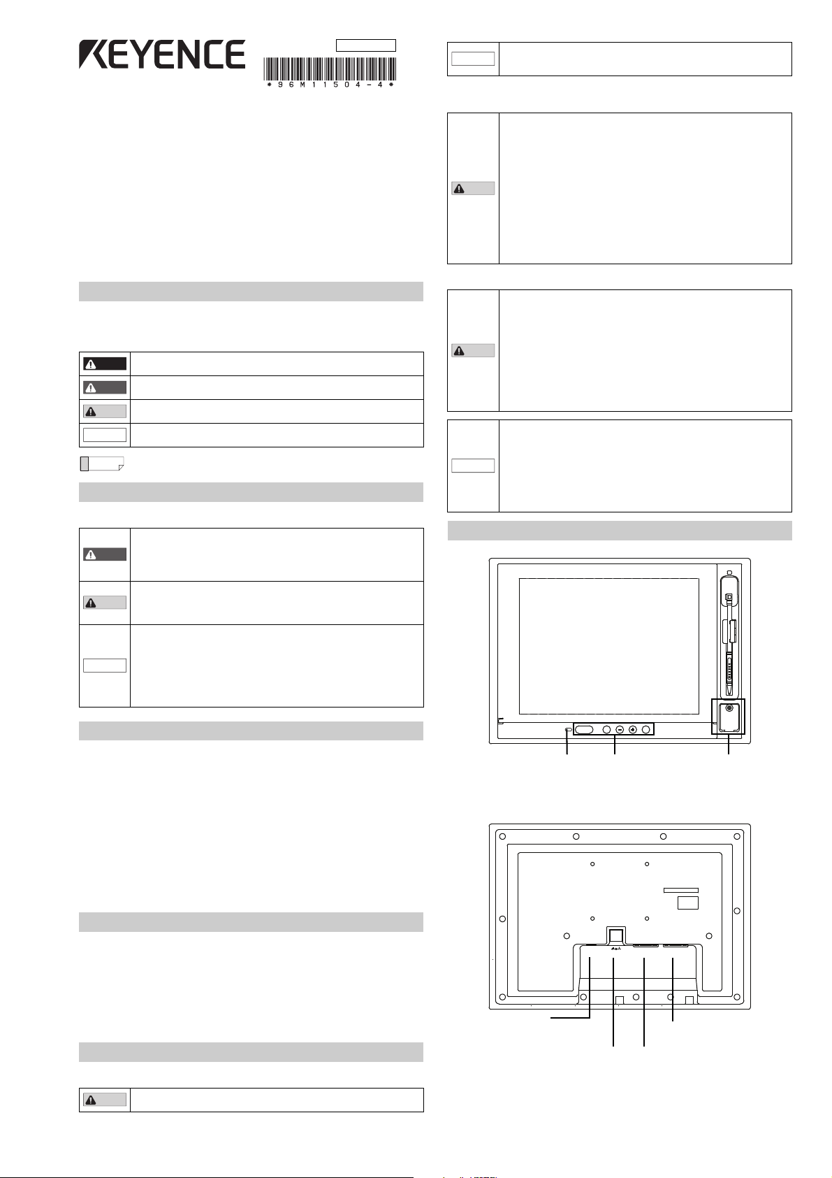
PANEL LOCK EXIT MENU
CONSOLE
CONSOLE OUT 24V DC= TOUCH PANEL RGB IN
PANEL LOCK display MENU button
+ button
- button
EXIT button
PANEL LOCK button
Console connector
Image signal input
Input connector for image signal
Touch panel signal output
Touch panel signal output
Console signal output
Output connector for console signal
for controller use
Power input terminal
Power connection terminal for the 24 VDC
(1.5 A)
96M11504
Touch Panel LCD Monitor
CA-MP120T
Instruction Manual
Read this manual before using the product in order to achieve maximum performance.
Keep this manual in a safe place after reading it so that it can be used at any time.
When using a switching regulator, make sure to ground the frame GND
terminal or GND terminal of the power supply. In addition, it is
recommended that the CA-MP120T be operated singly from a power source.
Installation Location
When installing the CA-MP120T, make sure to avoid locations with the following conditions.
• Locations where the CA-MP120T is exposed to direct sunlight
• Locations where the ambient temperature exceeds t he range of 0 to
+40°C (32 to 104°C), or where the temperature changes dramatically
• Locations with poor ventilation
• Locations where the relative humidity exceeds the range of 35 to
85%, or condensation occurs
• Locations where corrosive or flammable gas exists
• Locations where a large amount of dust, salt, or ferrous powder exists
• Locations where water, oil, or chemicals may splash onto the CA-MP120T
• Locations where the CA-MP120T is subjected directly to vibration or impact
• Locations where radiation noise and static electricity may affect
operation of the CA-MP120T
• Locate the CA-MP120T and cables as far as possible from
high-voltage lines and power lines. Otherwise, generated noise may
cause product malfunction or equipment failure
Introduction
Symbols
This manual uses the following symbols so that you can recognize important messages at a
glance. Please read it in its entirety.
It indicates a hazardous situation which, if not avoided, will result in
death or serious injury.
It indicates a hazardous situation which, if not avoided, could result in
death or serious injury.
It indicates a hazardous situation which, if not avoided, could result in
minor or moderate injury.
It indicates a situation which, if not avoided, could result in product
damage as well as property damage.
It indicates tips for better understanding or useful information.
Safety Information for the CA-MP120T
General Precautions
• Do not use this product for the purpose of protecting a human body
or a part of a human body.
• This product is not intended for use as explosion-proof product. Do
not use this product in a hazardous location and/or potentially
explosive atmosphere.
• When beginning or during operation, ensure that the par ts and
functions are operating correctly.
• In the unlikely event of malfunction, ensure that the proper safety
equipment is in place to prevent damage to other equipment.
• Please be aware that the functions and performance of the
CA-MP120T will not be guaranteed when the product is
disassembled or modified, or if used in any way other than described
in the specifications.
• When the CA-MP120T is used in combination with other instruments,
its functions and performance may be degraded to an unsatisfactory
level. Make sure to examine its performance before starting the
operation.
Handling
• Do not disassemble or modify the CA-MP120T, as this may cause
fire, electric shock, or equipment failure.
•
Turn the power off immediately if one of the following conditions occur.
Continuous use under abnormal conditions may cause fire, electric
shock, or equipment failure. Please contact your nearest KEYENCE
office for repairs.
- When liquid or a foreign material (such as water, oil, or chemical)
enters the product
- When a strong shock is applied to the product or its housing is
damaged
- When you notice smoke, an unusual smell, or noise coming from
the product CE
• Make sure to turn off power to the CA-MP120T and any connected
devices before connecting or disconnecting the cables. Otherwise,
the CA-MP120T and connected devices may become damaged.
• If a large amount of dir t or dust accumulates on the CA-MP120T,
remove it using a tightly squeezed cloth moistened with a dilute
solution of neutral detergent. Wipe the unit with a soft, dry cloth. Do
not wipe the CA-MP120T with a damp cloth or a cloth moistened with
benzine, thinner, or alcohol, as this may cause discoloration or
deformation of the unit.
Part Names and Usage
Precautions on Regulations and Standards
CE Marking
Keyence Corporation has confirmed that this product complies with the essential requirements
of the applicable EC Directive, based on the following spec ifications.
Be sure to consider the following specifications when using this product in the Member State
of European Union.
z EMC Directive (2004/108/EC)
• Applicable standard EMI: EN61326-1, ClassA
• The length of cable connected to the power input terminal must be less than 30 m.
Remarks: These specifications do not give any guarantee that the end-product with this
product incorporated complies with the essential requirements of EMC Directive.
The manufacturer of the end-product is solely responsible for the compliance on the
end-product itself according to EMC Directive.
Checking the Package Contents
The CA-MP120T package includes the following parts and equipment.
Verify that all parts and equipment are included in the package.
Color LCD monitor CA-MP120T .....................................1
Instruction Manual (This manual) ...................................1
Panel mounting brackets ................................................6
Stylus pen.......................................................................1
* We have thoroughly inspected the package contents before shipment.
However, in the event of defective or missing items, please contact your nearest
KEYENCE sales office.
Hints on Correct Use
Power supply
Do not use the CA-MP120T with a voltage other than 24 VDC, as this
may cause fire, electric shock, or equipment failure.
EMS: EN61326-1
1
Page 2
Connecting to the controller
When using a controller’s modular connector for touch
panel signal use, it is necessary to switch the port
function on the controller side. For details refer to the
controller manual.
Reference
Panel (Panel thickness): 1.0 to 4.0 mm
2
1
Mounting hook
Screw
Mounting bracket
Mounting bracket
Phillips screwdriver
NOTICE
NOTICE
Reference
Reference
PANEL LOCK
Image signal
input
Touch panel
signal input
Console signal
output
Connect by using an RGB monitor cable OP-66842 (3 m), an OP-87055
(10 m), or a commercially available analog RGB cable.
When using a D-sub9Pin connector on the controller side:
connect using a touch panel RS-232C cable OP-87258 (3 m), or
OP-87259 (10 m).
When using a modular connector on the controller side:
connect using a touch panel modular RS-232C cable OP-87264 (3 m),
or OP-87265 (10 m).
Connect the modular connector for console use with the console
connector cable OP-87260 (3 m) or the OP-87261 (10 m).
Console connector
The only consoles that can be connected are the OP-84231 or the OP-84236. Otherwise, do
not make any other connections because it may be the cause of erroneous operation.
When attempting to prevent water from entering the front surface, tighten the console cap
with 0.8 Nm.
PANEL LOCK
1. The PANEL LOCK will activate when the automatic adjustment indicator lights up or when
the PANEL LOCK button is held down.
2. The PANEL LOCK will be deactivated when the PANEL LOCK button is pressed.
Installation Procedure
1. Insert the CA-MP120T into the panel.
2. Using the 6 installation hooks on the top and bottom of the CA-MP120T, tighten the
screws of the mounting bracket using a Phyllis-head screwdriver.
• Tightening the mounting bracket with excessive force may deform
the casing. The proper tightening torque for achieving the drip-proof
feature is 0.3 Nm. However, note that a drip-proof effect may not be
obtained depending on the strength or shape of the panel.
• When installing the CA-MP120T, make sure to leave a minimum
clearance of 20 mm around the product.
The CA-MP120T can not only be installed to the panel bracket, it can be installed to the
monitor stand for CA Series LCD monitor use (optional). For details inquire to your nearest
KEYENCE office.
Connecting the 24 VDC Power Source
• Use electrical wiring AWG14 to AWG22.
• Make sure to connect the frame ground terminal for the 24 VDC
power source to a type D ground.
• The sizes of solderless connectors are shown below. Use connectors
that fit M3 screws.
• Tighten the screws with a torque of 0.5 to 0.75 Nm.
Y connector
5.8 mm or
smaller
Circular connector
5.8 mm or smaller
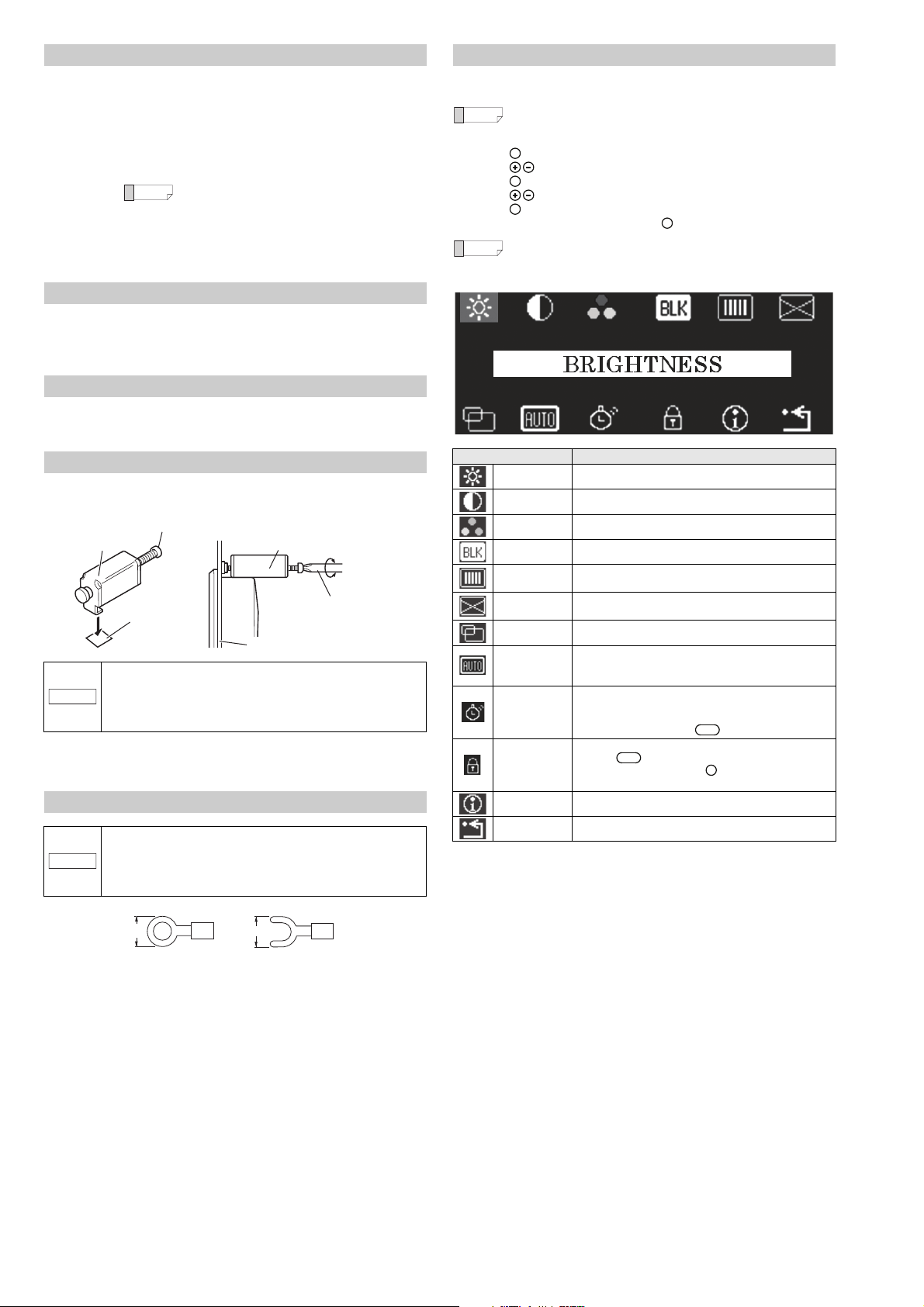
Adjustment Procedure
If your monitor needs adjustment due to ambient light, the installation angle, or the
characteristics of the connected device, follow the procedure below.
When no video signal is input, a blue screen (with message "NO SYNC
SIGNAL" for the first five minutes) is displayed instead of the setting menu.
1. Press the button on the rear of the monitor. The setting menu is displayed.
2. Press the button to move the cursor onto the item to change the setting.
3. Press the button to change the setting of the item.
4. Press the button to change the value/setting.
5. Press the button to return to the status of step 1.
6. When you complete the adjustment, press the button to exit the setting menu.
MENU
MENU
MENU
Auto-escape function
If no button is pressed for about 10 seconds, the setting menu display is
turned off. When this occurs, the change(s) made so far will be saved.
EXIT
Item Setting
BRIGHTNESS Adjusts the brightness of the backlight of the LCD panel.
CONTRAST Adjusts the contrast of the image.
COLOR MODE Adjusts the color tone of RGB individually.
BLACK LEVEL Adjusts the black level.
CLOCK
FOCUS
Adjusts the horizontal size of the screen by adjusting the
clock.
Reduces blurred characters and images by adjusting the
focus.
POSITION Adjusts the horizontal/vertical position of the screen.
AUTO
ADJUSTMENT
POWER
SAVING
BUTTON LOCK
The input image signal is adjusted automatically to the most
appropriate setting.
Adjustment object: POSITION/CLOCK/FOCUS
The screen is set when the screen automatically lights up or
when the PANEL LOCK is set. It is deactivated when the
touch panel is touched, or by console operation. The PANEL
LOCK is deactivated by the button.
All button operations are deactivated.
Also the button operation is deactivated.
The lock is released when the button is pressed for 3
PANEL LOCK
MENU
seconds or more.
INFORMATION Displays the device setting information, etc.
RECALL Resets the settings to the factory default (initial) settings.
*1
2
Page 3

Specifications
Reference
(49.5)
6
186
(Active display area)
247.4
(Active display area)
360
15
6.5
255
55.5
28
8.1
ø10
342
240
35
75
75
4-M4
Depth: 10
(Unit: mm)
Mounting screw
Mounting bracket
157.5
242
+1
0
344
+1
0
Panel thickness 1.6 to 4.0 mm
263
(Mounting bracket
external dimensions)
156.5
(Unit: mm)
Product name Touch Panel LCD Monitor
Model CA-MP120T
Display element a-Si, TFT active matrix method
Display color 16,777,216
No. of dots 1024 (W) x 768 (H) dots or 800 (W) x 600 (H) dots
Active display area
Backlight
Input signal
Input signal mode
245 (W) x 184 (H) mm
Approx. 100,000 hours (average)
(When installed in an upright position under 25°C (77°F))
Analog RGB signal (0.7 Vp-p, 75 Ω), Horizontal/vertical
synchronization signal
1024 (W) x 768 (H), Vertical frequency: 60 Hz or
800 (W) x 600 (H), Vertical frequency: 60 Hz
Input connector High-density D-sub 15-pin female (3-way, inch screw)
Touch panel connector D-sub 9-pin male (2-way, inch screw)
Console connector Connector for RJ45 use
Power-supply voltage 24 VDC ±10%
Current consumption 1.5 A max.
Ambient temperature 0 to +40°C (32 to 104°F)
Relative humidity 35 to 85%
Construction
Panel-mount type
Only the front face is dust-proof and splashproof equivalent to IP65
Weight Approx. 2.3 kg
The TFT LCD panels may have bright dots that always illuminate and dark
dots that never illuminate. This is inevitable due to the manufacturing
process and is not a product failure.
Dimensions
Touch panel LCD monitor CA-MP120T
Panel mounting diagram Panel cut measurement
3
Page 4

Copyright (c) 2011 KEYENCE CORPORATION. All rights reserved.
11504E 1015-4 96M11504 Printed in Japan
Warranties and Disclaimers
(1) KEYENCE warrants the Products to be free of defects in materials and workmanship for
a period of one (1) year from the date of shipment. If any models or samples were shown
to Buyer, such models or samples were used merely to illustrate the general type and
quality of the Products and not to represent that the Products would necessarily conform
to said models or samples. Any Products found to be defective must be shipped to
KEYENCE with all shipping costs paid by Buyer or offered to KEYENCE for inspection
and examination. Upon examination by KEYENCE, KEYENCE, at its sole option, will
refund the purchase price of, or repair or replace at no charge any Products found to be
defective. This warranty does not apply to any defects resulting from any action of Buyer,
including but not limited to improper installation, improper interfacing, improper repair,
unauthorized modification, misapplication and mishandling, such as exposure to
excessive current, heat, coldness, moisture, vibration or outdoors air. Components
which wear are not warranted.
(2) KEYENCE is pleased to offer suggestions on the use of its various Products. They are
only suggestions, and it is Buyer's responsibility to ascertain the fitness of the Products
for Buyer’s intended use. KEYENCE will not be responsible for any damages that may
result from the use of the Products.
(3) The Products and any samples ("Products/Samples") supplied to Buyer are not to be
used internally in humans, for human transportation, as safety devices or fail-safe
systems, unless their written specifications state otherwise. Should any Products/
Samples be used in such a manner or misused in any way, KEYENCE assumes no
responsibility, and additionally Buyer will indemnify KEYENCE and hold KEYENCE
harmless from any liability or damage whatsoever arising out of any misuse of the
Products/Samples.
(4) OTHER THAN AS STATED HEREIN, THE PRODUCTS/SAMPLES ARE PROVIDED
WITH NO OTHER WARRANTIES WHATSOEVER. ALL EXPRESS, IMPLIED, AND
STATUTORY WARRANTIES, INCLUDING, WITHOUT LIMITATION, THE
WARRANTIES OF MERCHANTABILITY, FITNESS FOR A PARTICULAR PURPOSE,
AND NON-INFRINGEMENT OF PROPRIETARY RIGHTS, ARE EXPRESSLY
DISCLAIMED.
IN NO EVENT SHALL KEYENCE AND ITS AFFILIATED ENTITIES BE LIABLE TO
ANY PERSON OR ENTITY FOR ANY DIRECT, INDIRECT, INCIDENTAL, PUNITIVE,
SPECIAL OR CONSEQUENTIAL DAMAGES (INCLUDING, WITHOUT LIMITATION,
ANY DAMAGES RESULTING FROM LOSS OF USE, BUSINESS INTERRUPTION,
LOSS OF INFORMATION, LOSS OR INACCURACY OF DATA, LOSS OF PROFITS,
LOSS OF SAVINGS, THE COST OF PROCUREMENT OF SUBSTITUTED GOODS,
SERVICES OR TECHNOLOGIES, OR FOR ANY MATTER ARISING OUT OF OR IN
CONNECTION WITH THE USE OR INABILITY TO USE THE PRODUCTS, EVEN IF
KEYENCE OR ONE OF ITS AFFILIATED ENTITIES WAS ADVISED OF A POSSIBLE
THIRD PARTY’S CLAIM FOR DAMAGES OR ANY OTHER CLAIM AGAINST BUYER.
In some jurisdictions, some of the foregoing warranty disclaimers or damage limitations
may not apply.
BUYER'S TRANSFER OBLIGATIONS:
If the Products/Samples purchased by Buyer are to be resold or delivered to a third party,
Buyer must provide such third party with a copy of this document, all specifications,
manuals, catalogs, leaflets and written information provided to Buyer pertaining to the
Products/Samples.
E 1101-3
4
 Loading...