


PC CONTROL COMMAND REFERENCE FOR THE TS-480HX/ SAT TRANSCEIVER
© 2003/11/28
09 08 07 06 05 04 03 02 01 00
PC CONTROL COMMAND
ABOUT THIS REFERENCE
All descriptions in this PC CONTROL COMMAND reference are for the users convenience only. KENWOOD will not support or warrantee this documentation in any way.
HARDWARE DESCRIPTION
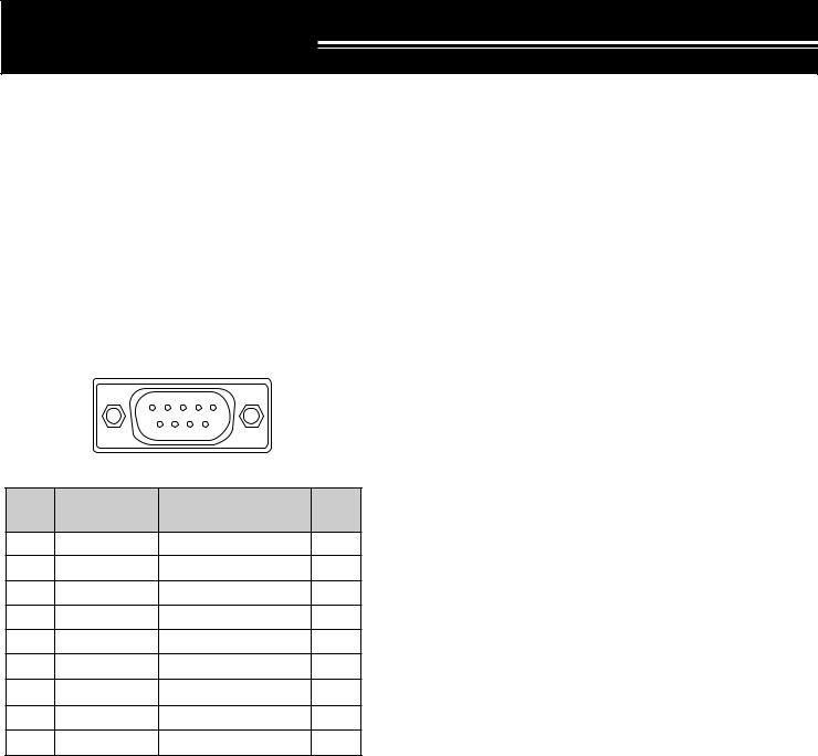
The TS-480 transceiver uses a full-duplex, asynchronous, serial interface for communicating through the male 9-pin D-sub connector. Each data is constructed with 1 start bit, 8 data bits, and 1 stop bit (4800 bps must be configured as 2 stop bits). No parity is used. The pinout and the pin functions of the COM connector on the transceiver are shown below:
Front view
|
1 |
2 |
3 |
4 |
5 |
|
|
6 |
7 |
|
8 |
9 |
|
|
|
COM |
|
|
||
COM |
COM Pin Name |
|
|
|
Function |
I/O |
Pin No. (Ref.: Computer) |
|
(Ref.: Transceiver) |
||||
|
|
|||||
1 |
NC |
|
|
|
— |
— |
2 |
RXD |
|
|
Transmit data |
Output |
|
3 |
TXD |
|
|
Receive data |
Input |
|
4 |
NC |
|
|
|
— |
— |
5 |
GND |
|
|
Signal ground |
|
|
6 |
NC |
|
|
|
— |
— |
7 |
RTS |
|
|
Receive enable |
Input |
|
8 |
CTS |
|
Transmit enable |
Output |
||
9 |
NC |
|
|
|
— |
— |
RXD: Transmit data is serial data transferred from the transceiver to the computer.
TXD: Receive data is serial data transferred from the computer to the transceiver.
GND: Signal ground pin
RTS: This signal is applied to the transceiver. It is used to inhibit transmit data from the transceiver when the computer is not ready to receive data. Transmit data is inhibited when the level is low.
CTS: This signal is applied from the transceiver. It is used to inhibit transmit data from the computer when the transceiver is not ready to receive data. Transmit data is stopped when the level is low.
CONTROL OPERATION
Most computers handle data in the form of “bits” and “bytes”. A bit is the smallest piece of information that a computer can handle. A byte is composed of eight bits. This is the most convenient form for most computer data. This data may be sent in the form of either serial or parallel data strings. The parallel method is faster but more complicated, while the serial method is slower and requires less complicated equipment. The serial form is, therefore, a less expensive alternative.
Serial data transmission uses time-division methods over a single line. Using a single line also offers the advantage of reducing the number of errors due to line noise.
Only 3 lines are required theoretically for control of the transceiver via the computer:
•Transmit data
•Receive data
•Ground
From a practical standpoint, it is also necessary to incorporate some means of controlling when this data transfer will occur. The computer and transceiver cannot be allowed to send data at the same time! The required control is achieved by using the RTS and CTS lines. To interface between the TS-480 transceiver and a PC, use a commercially available cable with a DB-9 female connector at each end. Each connector pin must be connected to the same pin number at the other end (a straight cable).
To control the transceiver from a PC, utilize the general purpose terminal program to send commands to the tranceiver. The transceiver responds the command accordingly.
For example, the transceiver is placed into the transmit mode whenever the character string “TX;” is sent from the computer. The character string “TX;” is called a PC control command.
You can further develop or create a script of the commands using a macro function of the terminal program. Kenwood also provides the remote control program, ARCP-480 at our Web site. You can download the program for free and try it out on your PC. Access http://www.kenwood.com/i/products/info/ amateur.html and follow the instructions.
1

PC CONTROL COMMAND
COMPUTER CONTROL COMMANDS |
■ Alphabetical Commands |
A computer control command is composed of an alphabetical command, various parameters, and the terminator that signals the end of the control command.
EXAMPLE: Command to set VFO A to 7 MHz
FA 00007000000 ;
Terminator
Parameters
Alphabetical command
Commands can be classified as shown below:
|
|
|
Input |
|
Set command |
|
|
|
|
|
(Sets a |
||
|
|
|
command |
|
||
|
|
|
|
|||
|
|
|
|
particular condition) |
||
|
|
|
(Input to the |
|
||
Computer |
|
transceiver) |
|
|
Read command |
|
|
|
|
||||
control |
|
|
|
|
|
|
|
|
|
|
(Reads an answer) |
||
commands |
|
|
|
|
||
|
|
|
|
|||
|
|
|
Output |
Answer command |
||
|
|
|
command |
|
||
|
|
|
(Transmits a condition) |
|||
|
|
|
(From the |
|||
|
|
|
|
|
||
|
|
|
transceiver) |
|
|
|
For example, note the following in the case of the FA command (Frequency of VFO A):
•To set the frequency to 7 MHz, the following command is sent from the computer to the transceiver:
“FA00007000000;” |
(Set command) |
•To read the frequency of VFO A, the following command is sent from the computer to the transceiver:
“FA;” |
(Read command) |
•When the Read command above has been sent, the following command is returned to the computer:
“FA00007000000;” |
(Answer command) |
Note:
Do not use the control characters 00 to 1Fh since they are either ignored or cause a “?” answer.
Program execution may be delayed while turning the Tuning control rapidly.
A command consists of 2 alphabetical characters. You may use either lower or upper case characters. The commands available for this transceiver are listed in the PC Control Command Tables from page 3.
■Parameters
Parameters are used to specify information necessary to implement the desired command. The parameters to be used for each command are predetermined. The number of digits assigned to each parameter is also predetermined. Refer to the Computer Control Commands and the PC Control Command Tables to configure the appropriate parameters.
When configuring parameters, be careful not to make the following mistakes.
(correct parameter: “IS+1000”)
IS1000; Not enough parameters specified (No direction given for the IF shift)
IS+100; Not enough digits
(Only three frequency digits given)
IS 
 +
+ 
 1000; Unnecessary characters between parameters
IS+10000; Too many digits
(Five frequency digits given)
Note: If a particular parameter is not applicable to this transceiver, the parameter digits should be filled using any character except the ASCII control codes (00 to 1Fh) and the terminator (;).
■Terminator
To signal the end of a command, it is necessary to use a semicolon (;). The digit where this special character must appear differs depending on the command used.
■Error Messages
In addition to the Answer command, the transceiver can send the following error messages.
Error |
Reason for Error |
|
Message |
||
|
||
?; |
• Command syntax was incorrect. |
|
|
• Command was not executed due to |
|
|
the current status of the transceiver |
|
|
(even though the command syntax |
|
|
was correct). |
|
|
Note: Occasionally this message may not |
|
|
appear due to microprocessor transients in the |
|
|
transceiver. |
|
|
|
|
E; |
A communication error occurred such |
|
|
as an overrun or framing error during a |
|
|
serial data transmission. |
|
|
|
|
O; |
Receive data was sent but processing |
|
|
was not completed. |
|
|
|
2

PC CONTROL COMMAND
PC CONTROL COMMAND TABLES
AC |
Sets or reads the internal antenna tuner status. |
|
|
|
Parameters: |
|||||||||
|
|
|
|
|
|
|
|
|
|
|
|
|
P1 |
|
|
|
|
|
|
|
|
|
|
|
|
|
|
|
0: RX-AT THRU |
|
1 |
2 |
3 |
4 |
|
5 |
6 |
7 |
|
8 |
9 |
|
10 |
|
|
|
|
|
1: RX-AT IN |
||||||||||
Set |
|
|
|
|
|
|
|
|
|
|
|
|
|
|
A |
C |
|
|
|
|
|
|
|
|
|
|
|
||
P1 |
P2 |
|
P3 |
; |
|
|
|
|
|
|
P2 |
|||
|
|
|
|
|
|
|
|
|||||||
|
|
|
|
|
|
|
|
|
|
|
|
|
|
0: TX-AT THRU |
|
1 |
2 |
3 |
4 |
|
5 |
6 |
7 |
|
8 |
9 |
|
10 |
|
|
|
|
|
1: TX-AT IN |
||||||||||
Read |
|
|
|
|
|
|
|
|
|
|
|
|
|
|
A |
C |
; |
|
|
|
|
|
|
|
|
|
|
P3 |
|
|
|
|
|
|
|
|
|
|
|
|
0: Stop tuning (Set)/ Tuning is stopped (Answer) |
|||
|
|
|
|
|
|
|
|
|
|
|
|
|
|
|
|
1 |
2 |
3 |
4 |
|
5 |
6 |
7 |
|
8 |
9 |
|
10 |
1: Start tuning (Set)/ Tuning is active (Answer) |
Answer |
A |
C |
P1 |
P2 |
|
P3 |
; |
|
|
|
|
|
|
|
|
|
|
|
|
|
|
|
|
||||||
|
|
|
|
|
|
|
|
|
|
|
|
|
|
|
|
|
|
|
|
|
|
|
|
|
|
|
|||
AG |
Sets or reads the AF gain. |
|
|
|
|
|
|
|
|
Parameters: |
||||
|
|
|
|
|
|
|
|
|
|
|
|
|
P1 |
|
|
|
|
|
|
|
|
|
|
|
|
|
|
|
0: Always 0 for the TS-480. |
|
1 |
2 |
3 |
4 |
|
5 |
6 |
7 |
|
8 |
9 |
|
10 |
|
|
|
|
|
P2 |
||||||||||
Set |
|
|
|
|
|
|
|
|
|
|
|
|
|
|
A |
G |
|
|
|
|
|
|
|
|
|
|
|
||
P1 |
P2 |
|
P2 |
P2 |
; |
|
|
|
|
|
000 (min.) ~ 255 (max.) |
|||
|
|
|
|
|
|
|
||||||||
|
|
|
|
|
|
|
|
|
|
|
|
|
|
|
|
1 |
2 |
3 |
4 |
|
5 |
6 |
7 |
|
8 |
9 |
|
10 |
|
Read |
A |
G |
P1 |
; |
|
|
|
|
|
|
|
|
|
|
|
|
|
|
|
|
|
|
|
|
|
||||
|
|
|
|
|
|
|
|
|
|
|
|
|
|
|
|
1 |
2 |
3 |
4 |
|
5 |
6 |
7 |
|
8 |
9 |
|
10 |
|
Answer |
A |
G |
P1 |
P2 |
|
P2 |
P2 |
; |
|
|
|
|
|
|
|
|
|
|
|
|
|
|
|||||||
|
|
|
|
|
|
|
|
|
|
|
|
|
||
|
|
|
|
|
||||||||||
AI |
Sets or reads the Auto Information (AI) function ON/ OFF. |
|
Parameters: |
|||||||||||
|
|
|
|
|
|
|
|
|
|
|
|
|
P1 |
|
|
|
|
|
|
|
|
|
|
|
|
|
|
|
0: AI OFF |
|
1 |
2 |
3 |
4 |
|
5 |
6 |
7 |
|
8 |
9 |
|
10 |
|
|
|
|
|
1: Only old AI format is ON |
||||||||||
Set |
|
|
|
|
|
|
|
|
|
|
|
|
|
|
A |
I |
P1 |
; |
|
|
|
|
|
|
|
|
|
2: Only extended AI format is ON |
|
|
|
|
|
|
|
|
|
|
|
|||||
|
|
|
|
|
|
|
|
|
|
|
|
|
|
3: Both formats are ON |
|
1 |
2 |
3 |
4 |
|
5 |
6 |
7 |
|
8 |
9 |
|
10 |
When the extended AI format is selected, the transceiver |
Read |
|
|
|
|
|
|
|
|
|
|
|
|
|
|
A |
I |
; |
|
|
|
|
|
|
|
|
|
|
||
|
|
|
|
|
|
|
|
|
|
|
automatically sends the parameters. |
|||
|
|
|
|
|
|
|
|
|
|
|
|
|
|
When the old AI is ON and the IF parameters change, the |
|
1 |
2 |
3 |
4 |
|
5 |
6 |
7 |
|
8 |
9 |
|
10 |
|
|
|
|
|
transceiver sends the IF command every 1.5 seconds. |
||||||||||
Answer |
|
|
|
|
|
|
|
|
|
|
|
|
|
|
A |
I |
P1 |
; |
|
|
|
|
|
|
|
|
|
When the transceiver is turned OFF, the AI parameter |
|
|
|
|
|
|
|
|
|
|
|
becomes 0. |
||||
|
|
|
|
|
|
|
|
|
|
|
|
|
|
|
|
|
|
|
|
|
|
|
|
|
|
|
|
|
|
|
|
|
|
|
|
|
|
|||||||
AN |
Selects the antenna connector ANT1/ ANT2. |
|
|
|
|
Parameters: |
||||||||
|
|
|
|
|
|
|
|
|
|
|
|
|
P1 |
|
|
|
|
|
|
|
|
|
|
|
|
|
|
|
1: Selects ANT1 |
|
1 |
2 |
3 |
4 |
|
5 |
6 |
7 |
|
8 |
9 |
|
10 |
|
|
|
|
|
2: Selects ANT2 |
||||||||||
Set |
A |
N |
P1 |
; |
|
|
|
|
|
|
|
|
|
|
|
|
|
|
|
|
|
|
|
|
|||||
|
|
|
|
|
|
|
|
|
|
|
||||
|
|
|
|
|
|
|
|
|
|
|
|
|
|
|
|
1 |
2 |
3 |
4 |
|
5 |
6 |
7 |
|
8 |
9 |
|
10 |
|
Read |
A |
N |
; |
|
|
|
|
|
|
|
|
|
|
|
|
|
|
|
|
|
|
|
|
|
|
|
|||
|
|
|
|
|
|
|
|
|
|
|
|
|
|
|
|
1 |
2 |
3 |
4 |
|
5 |
6 |
7 |
|
8 |
9 |
|
10 |
|
Answer |
|
|
|
|
|
|
|
|
|
|
|
|
|
|
A |
N |
P1 |
; |
|
|
|
|
|
|
|
|
|
|
|
|
|
|
|
|
|
|
|
|
|
|
||||
|
|
|
|
|
|
|
|
|
|
|
|
|
||
|
|
|
|
|
|
|
||||||||
AS |
Sets or reads the Auto Mode function parameters. |
|
|
|
Parameters: |
|||||||||
|
|
|
|
|
|
|
|
|
|
|
|
|
P1 |
|
|
|
|
|
|
|
|
|
|
|
|
|
|
|
0: Always 0 for the TS-480. |
|
1 |
2 |
3 |
4 |
|
5 |
6 |
7 |
|
8 |
9 |
|
10 |
|
|
|
|
|
P2 |
||||||||||
|
A |
S |
|
|
|
|
|
|
|
|
|
|
|
|
|
P1 |
P2 |
|
P2 |
P3 |
P3 |
|
P3 |
P3 |
|
P3 |
00 ~ 31: HF ~ 50 MHz band (32 points) |
||
Set |
|
|
|
|
|
|
|
|
|
|
|
|
|
P3 |
11 |
12 |
13 |
14 |
|
15 |
16 |
17 |
|
18 |
19 |
|
20 |
||
|
|
|
|
Frequency in Hz (11-digit). Unused digit(s) must be 0. |
||||||||||
|
|
|
|
|
|
|
|
|
|
|
|
|
|
|
|
P3 |
P3 |
P3 |
P3 |
P3 |
P3 |
P4 |
|
; |
|
|
|
P4 |
|
|
|
|
|
|
0: Reserved |
|||||||||
|
|
|
|
|
|
|
|
|
|
|
|
|
|
|
|
1 |
2 |
3 |
4 |
|
5 |
6 |
7 |
|
8 |
9 |
|
10 |
1: LSB |
Read |
|
|
|
|
|
|
|
|
|
|
|
|
|
2: USB |
A |
S |
P1 |
P2 |
|
P2 |
; |
|
|
|
|
|
|
||
|
|
|
|
|
|
|
|
3: CW |
||||||
|
|
|
|
|
|
|
|
|
|
|
|
|
|
4: FM |
|
1 |
2 |
3 |
4 |
|
5 |
6 |
7 |
|
8 |
9 |
|
10 |
|
|
|
|
|
5: AM |
||||||||||
|
A |
S |
|
|
|
|
|
|
|
|
|
|
|
|
|
P1 |
P2 |
|
P2 |
P3 |
P3 |
|
P3 |
P3 |
|
P3 |
6: FSK |
||
Answer |
|
|
|
|
|
|
|
|
|
|
|
|
|
7: CWR (CW Reverse) |
11 |
12 |
13 |
14 |
|
15 |
16 |
17 |
|
18 |
19 |
|
20 |
||
|
|
|
|
8: Reserved |
||||||||||
|
P3 |
P3 |
P3 |
P3 |
P3 |
P3 |
P4 |
|
; |
|
|
|
9: FSR (FSK Reverse) |
|
|
|
|
|
|
|
|||||||||
|
|
|
|
|
|
|
|
|
|
|
|
|
|
|
3

PC CONTROL COMMAND
BC |
Sets or reads the Beat Canceller function status. |
|
|
Parameters: |
||||||||
|
|
|
|
|
|
|
|
|
|
|
P1 |
|
|
|
|
|
|
|
|
|
|
|
|
|
0: Beat Canceller OFF |
|
1 |
2 |
3 |
4 |
5 |
|
6 |
7 |
8 |
9 |
10 |
|
|
|
1: Beat Canceller 1 (BC1) ON |
||||||||||
Set |
|
|
|
|
|
|
|
|
|
|
|
|
B |
C |
|
|
|
|
|
|
|
|
|
||
P1 |
; |
|
|
|
|
|
|
|
2: Beat Canceller 2 (BC2) ON |
|||
|
|
|
|
|
|
|
|
|||||
|
|
|
|
|
|
|
|
|
|
|
|
|
|
1 |
2 |
3 |
4 |
5 |
|
6 |
7 |
8 |
9 |
10 |
|
Read |
B |
C |
; |
|
|
|
|
|
|
|
|
|
|
|
|
|
|
|
|
|
|
|
|||
|
|
|
|
|
|
|
|
|
|
|
|
|
|
1 |
2 |
3 |
4 |
5 |
|
6 |
7 |
8 |
9 |
10 |
|
Answer |
B |
C |
P1 |
; |
|
|
|
|
|
|
|
|
|
|
|
|
|
|
|
|
|
||||
|
|
|
|
|
|
|
|
|
|
|
|
|
|
|
|
|
|
|
|
|
|||||
BD |
Moves down the frequency band. |
|
|
|
|
|
Parameters: |
|||||
|
|
|
|
|
|
|
|
|
|
|
None |
|
|
|
|
|
|
|
|
|
|
|
|
|
|
|
1 |
2 |
3 |
4 |
5 |
|
6 |
7 |
8 |
9 |
10 |
|
Set |
B |
D |
; |
|
|
|
|
|
|
|
|
|
|
|
|
|
|
|
|
|
|
|
|||
|
|
|
|
|
|
|
|
|
|
|
|
|
|
1 |
2 |
3 |
4 |
5 |
|
6 |
7 |
8 |
9 |
10 |
|
Read |
|
|
|
|
|
|
|
|
|
|
|
|
|
|
|
|
|
|
|
|
|
|
|
|
|
|
|
|
|
|
|
|
|
|
|
|
|
|
|
1 |
2 |
3 |
4 |
5 |
|
6 |
7 |
8 |
9 |
10 |
|
Answer |
|
|
|
|
|
|
|
|
|
|
|
|
|
|
|
|
|
|
|
|
|
|
|
|
|
|
|
|
|
|
|
|
|
|
|
|
|
|
|
|
|
|
|
|
|
|
|
|
|
|
|
BU |
Moves up the frequency band. |
|
|
|
|
|
Parameters: |
|||||
|
|
|
|
|
|
|
|
|
|
|
None |
|
|
|
|
|
|
|
|
|
|
|
|
|
|
|
1 |
2 |
3 |
4 |
5 |
|
6 |
7 |
8 |
9 |
10 |
|
Set |
|
|
|
|
|
|
|
|
|
|
|
|
B |
U |
; |
|
|
|
|
|
|
|
|
|
|
|
|
|
|
|
|
|
|
|
|
|||
|
|
|
|
|
|
|
|
|
|
|
|
|
|
1 |
2 |
3 |
4 |
5 |
|
6 |
7 |
8 |
9 |
10 |
|
Read |
|
|
|
|
|
|
|
|
|
|
|
|
|
|
|
|
|
|
|
|
|
|
|
|
|
|
|
|
|
|
|
|
|
|
|
|
|
|
|
1 |
2 |
3 |
4 |
5 |
|
6 |
7 |
8 |
9 |
10 |
|
Answer |
|
|
|
|
|
|
|
|
|
|
|
|
|
|
|
|
|
|
|
|
|
|
|
|
|
|
|
|
|
|
|
|
|
|||||
BY |
Reads the busy signal status. |
|
|
|
|
|
Parameters: |
|||||
|
|
|
|
|
|
|
|
|
|
|
P1 |
|
|
|
|
|
|
|
|
|
|
|
|
|
Transceiver status |
|
1 |
2 |
3 |
4 |
5 |
|
6 |
7 |
8 |
9 |
10 |
|
|
|
0: Not busy |
||||||||||
Set |
|
|
|
|
|
|
|
|
|
|
|
|
|
|
|
|
|
|
|
|
|
|
|
1: Busy |
|
|
|
|
|
|
|
|
|
|
|
|
|
|
|
|
|
|
|
|
|
|
|
|
|
|
P2 |
|
1 |
2 |
3 |
4 |
5 |
|
6 |
7 |
8 |
9 |
10 |
|
|
|
Sub-receiver status (Not applicable for the TS-480) |
||||||||||
Read |
B |
Y |
; |
|
|
|
|
|
|
|
|
0: Always 0 for TS-480. |
|
|
|
|
|
|
|
|
|
|
|||
|
|
|
|
|
|
|
|
|
|
|
|
|
|
1 |
2 |
3 |
4 |
5 |
|
6 |
7 |
8 |
9 |
10 |
|
Answer |
|
|
|
|
|
|
|
|
|
|
|
|
B |
Y |
P1 |
P2 |
; |
|
|
|
|
|
|
|
|
|
|
|
|
|
|
|
|
|||||
|
|
|
|
|
|
|
|
|
|
|
|
|
|
|
|
|
|||||||||
CA |
Sets and reads the CW Auto Zero-beat function status. |
|
Parameters: |
|||||||||
|
|
|
|
|
|
|
|
|
|
|
P1 |
|
|
|
|
|
|
|
|
|
|
|
|
|
0: Cancels CW Auto Zero-beat function/ Not active |
|
1 |
2 |
3 |
4 |
5 |
|
6 |
7 |
8 |
9 |
10 |
|
|
|
1: Activates CW Auto Zero-beat function/ Active |
||||||||||
Set |
C |
A |
P1 |
; |
|
|
|
|
|
|
|
|
|
|
|
|
|
|
|
|
|||||
|
|
|
|
|
|
|
|
|
||||
|
|
|
|
|
|
|
|
|
|
|
|
|
|
1 |
2 |
3 |
4 |
5 |
|
6 |
7 |
8 |
9 |
10 |
|
Read |
|
|
|
|
|
|
|
|
|
|
|
|
C |
A |
; |
|
|
|
|
|
|
|
|
|
|
|
|
|
|
|
|
|
|
|
|
|||
|
|
|
|
|
|
|
|
|
|
|
|
|
|
1 |
2 |
3 |
4 |
5 |
|
6 |
7 |
8 |
9 |
10 |
|
Answer |
|
|
|
|
|
|
|
|
|
|
|
|
C |
A |
P1 |
; |
|
|
|
|
|
|
|
|
|
|
|
|
|
|
|
|
|
|
||||
|
|
|
|
|
|
|
|
|
|
|
|
|
4

PC CONTROL COMMAND
CH |
Move the current VFO frenquency 1 step up, using the MULTI |
Parameters: |
||||||||||
control. |
|
|
|
|
|
|
|
|
|
P1 |
||
|
|
|
|
|
|
|
|
|
|
|
|
0: Move the MULTI control 1 step up |
|
1 |
|
2 |
3 |
4 |
5 |
6 |
7 |
8 |
9 |
10 |
|
|
|
1: Move the MULTI control 1 step down |
||||||||||
Set |
|
|
|
|
|
|
|
|
|
|
|
|
C |
|
H |
P1 |
; |
|
|
|
|
|
|
||
|
|
|
|
|
|
|
|
|||||
|
|
|
|
|
|
|
|
In VFO mode, CH command overrides the MHz Up/ Down |
||||
|
|
|
|
|
|
|
|
|
|
|
|
|
|
1 |
|
2 |
3 |
4 |
5 |
6 |
7 |
8 |
9 |
10 |
|
|
|
mode of the TS-480 transceiver. |
||||||||||
Read |
|
|
|
|
|
|
|
|
|
|
|
|
|
|
|
|
|
|
|
|
|
|
|
|
|
|
1 |
|
2 |
3 |
4 |
5 |
6 |
7 |
8 |
9 |
10 |
|
Answer |
|
|
|
|
|
|
|
|
|
|
|
|
|
|
|
|
|
|
|
|
|
|
|
|
|
|
|
|
|
|
|
|||||||
CN |
Sets and reads the CTCSS tone number. |
|
|
|
Parameters: |
|||||||
|
|
|
|
|
|
|
|
|
|
|
P1 |
|
|
|
|
|
|
|
|
|
|
|
|
|
00 ~ 41 |
|
1 |
|
2 |
3 |
4 |
5 |
6 |
7 |
8 |
9 |
10 |
|
|
|
|
||||||||||
Set |
C |
|
N |
P1 |
P1 |
; |
|
|
|
|
|
Refer to page 33 of the TS-480 instruction manual for the |
|
|
|
|
|
|
|
||||||
|
|
|
|
|
|
|
|
|
|
|
|
CTCSS tone numbers and frequencies. |
|
1 |
|
2 |
3 |
4 |
5 |
6 |
7 |
8 |
9 |
10 |
|
|
|
|
||||||||||
Read |
|
|
|
|
|
|
|
|
|
|
|
|
C |
|
N |
; |
|
|
|
|
|
|
|
|
|
|
|
|
|
|
|
|
|
|
|
|||
|
|
|
|
|
|
|
|
|
|
|
|
|
|
1 |
|
2 |
3 |
4 |
5 |
6 |
7 |
8 |
9 |
10 |
|
Answer |
|
|
|
|
|
|
|
|
|
|
|
|
C |
|
N |
P1 |
P1 |
; |
|
|
|
|
|
|
|
|
|
|
|
|
|
|
|
|||||
|
|
|
|
|
|
|
|
|
|
|
|
|
|
|
|
|
|
|
|||||||
CT |
Sets and reads the CTCSS function status. |
|
|
|
Parameters: |
|||||||
|
|
|
|
|
|
|
|
|
|
|
P1 |
|
|
|
|
|
|
|
|
|
|
|
|
|
0: CTCSS function OFF |
|
1 |
|
2 |
3 |
4 |
5 |
6 |
7 |
8 |
9 |
10 |
|
|
|
1: CTCSS function ON |
||||||||||
Set |
|
|
|
|
|
|
|
|
|
|
|
|
C |
|
T |
P1 |
; |
|
|
|
|
|
|
||
|
|
|
|
|
|
|
|
|||||
|
|
|
|
|
|
|
|
|
||||
|
|
|
|
|
|
|
|
|
|
|
|
|
|
1 |
|
2 |
3 |
4 |
5 |
6 |
7 |
8 |
9 |
10 |
|
Read |
|
|
|
|
|
|
|
|
|
|
|
|
C |
|
T |
; |
|
|
|
|
|
|
|
|
|
|
|
|
|
|
|
|
|
|
|
|||
|
|
|
|
|
|
|
|
|
|
|
|
|
|
1 |
|
2 |
3 |
4 |
5 |
6 |
7 |
8 |
9 |
10 |
|
Answer |
C |
|
T |
P1 |
; |
|
|
|
|
|
|
|
|
|
|
|
|
|
|
|
|
||||
|
|
|
|
|
|
|
|
|
|
|
|
|
|
|
|||||||||||
DL |
Sets and reads the Digital Noise Limiter (DNL) function status. |
Parameters: |
||||||||||
|
|
|
|
|
|
|
|
|
|
|
P1 |
|
|
|
|
|
|
|
|
|
|
|
|
|
0: DNL function OFF |
|
1 |
|
2 |
3 |
4 |
5 |
6 |
7 |
8 |
9 |
10 |
|
|
|
1: DNL function ON |
||||||||||
Set |
D |
|
L |
|
|
|
|
|
|
|
|
|
|
P1 |
P2 |
P2 |
; |
|
|
|
|
P2 |
|||
|
|
|
|
|
|
|||||||
|
|
|
|
|
|
|
|
|
|
|
|
00: DNL Level 1 |
|
1 |
|
2 |
3 |
4 |
5 |
6 |
7 |
8 |
9 |
10 |
|
|
|
01: DNL Level 2 |
||||||||||
Read |
D |
|
L |
; |
|
|
|
|
|
|
|
02: DNL Level 3 |
|
|
|
|
|
|
|
|
|
|
|||
|
|
|
|
|
|
|
|
|
|
|
|
|
|
1 |
|
2 |
3 |
4 |
5 |
6 |
7 |
8 |
9 |
10 |
|
Answer |
|
|
|
|
|
|
|
|
|
|
|
|
D |
|
L |
P1 |
P2 |
P2 |
; |
|
|
|
|
|
|
|
|
|
|
|
|
|
||||||
|
|
|
|
|
|
|
|
|
|
|
|
|
|
|
|
|
|
|
|
||||||
DN |
Emulates the microphone DWN key. |
|
|
|
|
Parameters: |
||||||
|
|
|
|
|
|
|
|
|
|
|
P1 |
|
|
|
|
|
|
|
|
|
|
|
|
|
00 ~ 99 |
|
1 |
|
2 |
3 |
4 |
5 |
6 |
7 |
8 |
9 |
10 |
|
|
|
|
||||||||||
Set |
D |
|
N |
P1 |
P1 |
; |
|
|
|
|
|
If no P1 parameter is specified, the command is interpreted |
|
|
|
|
|
|
|
||||||
|
|
|
|
|
|
|
|
|
|
|
|
as 1 step down. |
|
1 |
|
2 |
3 |
4 |
5 |
6 |
7 |
8 |
9 |
10 |
|
|
|
In Memory mode and Quick Memory mode, the command |
||||||||||
Read |
|
|
|
|
|
|
|
|
|
|
|
|
|
|
|
|
|
|
|
|
|
|
|
without a parameter is treated as a Memory channel down |
|
|
|
|
|
|
|
|
|
|
|
|
|
command. With parameters, it is treated as the frequency |
|
1 |
|
2 |
3 |
4 |
5 |
6 |
7 |
8 |
9 |
10 |
down command. |
Answer |
|
|
|
|
|
|
|
|
|
|
|
|
|
|
|
|
|
|
|
|
|
|
|
|
|
|
|
|
|
|
|
|
|
|
|
|
|
|
5

PC CONTROL COMMAND
EX |
Sets or reads the Extension Menu. |
|
|
|
|
Parameters: |
||||||
|
|
|
|
|
|
|
|
|
|
P1 |
||
|
|
|
|
|
|
|
|
|
|
|
000 ~ 060: Menu No. |
|
|
1 |
2 |
3 |
4 |
5 |
6 |
7 |
8 |
9 |
10 |
||
|
P2 |
|||||||||||
|
|
|
|
|
|
|
|
|
|
|
||
|
E |
X |
|
|
|
|
|
|
|
|
||
|
P1 |
P1 |
P1 |
P2 |
P2 |
P3 |
P4 |
P5 |
00: Always 00 for the TS-480 |
|||
Set |
|
|
|
|
|
|
|
|
|
|
P3 |
|
11 |
12 |
13 |
14 |
15 |
16 |
17 |
18 |
19 |
20 |
|||
|
0: Always 0 for the TS-480 |
|||||||||||
|
P5 |
; |
|
|
|
|
|
|
|
|
P4 |
|
|
|
|
|
|
|
|
|
|
0: Always 0 for the TS-480 |
|||
|
|
|
|
|
|
|
|
|
|
|
||
|
1 |
2 |
3 |
4 |
5 |
6 |
7 |
8 |
9 |
10 |
P5 |
|
Read |
|
|
|
|
|
|
|
|
|
|
A string of characters (Variable length) |
|
E |
X |
P1 |
P1 |
P1 |
P2 |
P2 |
P3 |
P4 |
; |
|||
|
Normally 1-digit for the TS-480. |
|||||||||||
|
|
|
|
|
|
|
|
|
|
|
Menu No. 32, 35 and 48 ~ 52 use 2-digit parameters. |
|
|
1 |
2 |
3 |
4 |
5 |
6 |
7 |
8 |
9 |
10 |
||
|
|
|||||||||||
|
|
|
|
|
|
|
|
|
|
|
|
|
|
E |
X |
P1 |
P1 |
P1 |
P2 |
P2 |
P3 |
P4 |
P5 |
Command example: |
|
Answer |
|
|
|
|
|
|
|
|
|
|
Display brightness |
|
11 |
12 |
13 |
14 |
15 |
16 |
17 |
18 |
19 |
20 |
|||
|
EX00000000; (Display illumination OFF). |
|||||||||||
|
|
|
|
|
|
|
|
|
|
|
||
|
P5 |
; |
|
|
|
|
|
|
|
|
EX00000003; (Display brightness level 3). |
|
|
|
|
|
|
|
|
|
|
|
|||
|
|
|
|
|
|
|
|
|
|
|
|
|
6

PC CONTROL COMMAND
Menu |
Function |
|
|
|
|
EX command parameter P5 |
|
|
|
||||
|
|
|
|
|
|
|
|
|
|
|
|||
No. |
0 |
1 |
2 |
3 |
4 |
5 |
6 |
7 |
8 |
9 |
Over |
||
|
|||||||||||||
|
|
||||||||||||
|
|
|
|
|
|
|
|
|
|
|
|
|
|
000 |
Display brightness |
OFF |
1 |
2 |
3 |
4 |
|
|
|
|
|
|
|
|
|
|
|
|
|
|
|
|
|
|
|
|
|
001 |
Key illumination |
OFF |
ON |
|
|
|
|
|
|
|
|
|
|
|
|
|
|
|
|
|
|
|
|
|
|
|
|
002 |
Auto Mode operation |
OFF |
ON |
|
|
|
|
|
|
|
|
|
|
|
|
|
|
|
|
|
|
|
|
|
|
|
|
003 |
Tuning control adjustment rate |
250 |
500 |
1000 |
|
|
|
|
|
|
|
(Hz) |
|
|
|
|
|
|
|
|
|
|
|
|
|
|
|
004 |
Tuning with Tuning control in FM |
OFF |
ON |
|
|
|
|
|
|
|
|
|
|
mode |
|
|
|
|
|
|
|
|
|
||||
|
|
|
|
|
|
|
|
|
|
|
|
||
|
|
|
|
|
|
|
|
|
|
|
|
|
|
005 |
Rounds off VFO frequencies |
OFF |
ON |
|
|
|
|
|
|
|
|
|
|
changed by using the MULTI control |
|
|
|
|
|
|
|
|
|
||||
|
|
|
|
|
|
|
|
|
|
|
|
||
|
9 kHz frequency step size for the |
|
|
|
|
|
|
|
|
|
|
|
|
006 |
MULTI control in AM mode on the |
OFF |
ON |
|
|
|
|
|
|
|
|
|
|
|
AM broadcast band |
|
|
|
|
|
|
|
|
|
|
|
|
007 |
Tunable (ON) or fixed (OFF) memory |
OFF |
ON |
|
|
|
|
|
|
|
|
|
|
channel frequencies |
|
|
|
|
|
|
|
|
|
||||
|
|
|
|
|
|
|
|
|
|
|
|
||
|
|
|
|
|
|
|
|
|
|
|
|
|
|
008 |
Program scan partially slowed |
OFF |
ON |
|
|
|
|
|
|
|
|
|
|
|
|
|
|
|
|
|
|
|
|
|
|
|
|
009 |
Slow down frequency range for the |
100 |
200 |
300 |
400 |
500 |
|
|
|
|
|
(Hz) |
|
Program scan |
|
|
|
|
|
||||||||
|
|
|
|
|
|
|
|
|
|
|
|
||
|
|
|
|
|
|
|
|
|
|
|
|
|
|
010 |
Program scan hold |
OFF |
ON |
|
|
|
|
|
|
|
|
|
|
|
|
|
|
|
|
|
|
|
|
|
|
|
|
011 |
Scan resume method |
to |
co |
|
|
|
|
|
|
|
|
|
|
|
|
|
|
|
|
|
|
|
|
|
|
|
|
012 |
Beep output level |
OFF |
1 |
2 |
3 |
4 |
5 |
6 |
7 |
8 |
9 |
|
|
|
|
|
|
|
|
|
|
|
|
|
|
|
|
013 |
TX sidetone volume |
OFF |
1 |
2 |
3 |
4 |
5 |
6 |
7 |
8 |
9 |
|
|
|
|
|
|
|
|
|
|
|
|
|
|
|
|
014 |
VGS-1 message playback volume |
OFF |
1 |
2 |
3 |
4 |
5 |
6 |
7 |
8 |
9 |
|
|
|
|
|
|
|
|
|
|
|
|
|
|
|
|
015 |
VGS-1 announcement volume |
OFF |
1 |
2 |
3 |
4 |
5 |
6 |
7 |
|
|
|
|
|
|
|
|
|
|
|
|
|
|
|
|
|
|
016 |
VGS-1 announcement speed |
OFF |
1 |
2 |
3 |
4 |
|
|
|
|
|
|
|
|
|
|
|
|
|
|
|
|
|
|
|
|
|
017 |
Use CW IF filter for SSB reception |
OFF |
ON |
|
|
|
|
|
|
|
|
|
|
|
|
|
|
|
|
|
|
|
|
|
|
|
|
018 |
DSP RX equalizer |
OFF |
Hb1 |
Hb2 |
FP |
bb1 |
bb2 |
c |
U |
|
|
|
|
|
|
|
|
|
|
|
|
|
|
|
|
|
|
019 |
DSP TX equalizer |
OFF |
Hb1 |
Hb2 |
FP |
bb1 |
bb2 |
c |
U |
|
|
|
|
|
|
|
|
|
|
|
|
|
|
|
|
|
|
020 |
DSP TX filter bandwidth for SSB or |
2.0 |
2.4 |
|
|
|
|
|
|
|
|
|
|
AM |
|
|
|
|
|
|
|
|
|
||||
|
|
|
|
|
|
|
|
|
|
|
|
||
|
|
|
|
|
|
|
|
|
|
|
|
|
|
021 |
Fine transmission power tuning |
OFF |
ON |
|
|
|
|
|
|
|
|
|
|
|
|
|
|
|
|
|
|
|
|
|
|
|
|
022 |
Time-out timer |
OFF |
3 |
5 |
10 |
20 |
30 |
|
|
|
|
(minutes) |
|
|
|
|
|
|
|
|
|
|
|
|
|
|
|
023 |
Transverter frequency display |
OFF |
ON |
|
|
|
|
|
|
|
|
|
|
|
|
|
|
|
|
|
|
|
|
|
|
|
|
024 |
Output power adjustment for |
OFF |
ON |
|
|
|
|
|
|
|
|
|
|
Transverter |
|
|
|
|
|
|
|
|
|
||||
|
|
|
|
|
|
|
|
|
|
|
|
||
|
|
|
|
|
|
|
|
|
|
|
|
|
|
025 |
TX hold when AT completes the |
OFF |
ON |
|
|
|
|
|
|
|
|
|
|
tuning |
|
|
|
|
|
|
|
|
|
||||
|
|
|
|
|
|
|
|
|
|
|
|
||
026 |
In-line AT while receiving |
OFF |
ON |
|
|
|
|
|
|
|
|
|
|
|
|
|
|
|
|
|
|
|
|
|
|
|
|
027 |
Control method for the external AT |
At1 |
At2 |
|
|
|
|
|
|
|
|
|
|
|
|
|
|
|
|
|
|
|
|
|
|
|
|
028 |
Linear amplifier control delay for HF |
OFF |
1 |
2 |
3 |
|
|
|
|
|
|
|
|
band |
|
|
|
|
|
|
|
||||||
|
|
|
|
|
|
|
|
|
|
|
|
||
|
|
|
|
|
|
|
|
|
|
|
|
|
|
029 |
Linear amplifier control delay for 50 |
OFF |
1 |
2 |
3 |
|
|
|
|
|
|
|
|
MHz band |
|
|
|
|
|
|
|
||||||
|
|
|
|
|
|
|
|
|
|
|
|
||
|
|
|
|
|
|
|
|
|
|
|
|
|
|
030 |
Constant recording |
OFF |
ON |
|
|
|
|
|
|
|
|
|
|
|
|
|
|
|
|
|
|
|
|
|
|
|
|
031 |
Repeat the playback |
OFF |
ON |
|
|
|
|
|
|
|
|
|
|
|
|
|
|
|
|
|
|
|
|
|
|
|
|
032 |
Interval time for repeating the |
0 |
1 |
2 |
3 |
4 |
5 |
6 |
7 |
8 |
9 |
~ 60 |
|
playback |
(in steps of 1 s) |
||||||||||||
|
|
|
|
|
|
|
|
|
|
|
|||
|
|
|
|
|
|
|
|
|
|
|
|
|
|
033 |
Keying priority over playback |
OFF |
ON |
|
|
|
|
|
|
|
|
|
|
|
|
|
|
|
|
|
|
|
|
|
|
|
|
034 |
CW RX pitch/ TX sidetone frequency |
400 |
450 |
500 |
550 |
600 |
650 |
700 |
750 |
800 |
850 |
~ 1000 |
|
(in steps of 50) |
|||||||||||||
|
|
|
|
|
|
|
|
|
|
|
|
||
|
|
|
|
|
|
|
|
|
|
|
|
|
|
035 |
CW keying dot, dash weight ratio |
AUTO |
2.5 |
2.6 |
2.7 |
2.8 |
2.9 |
3.0 |
3.1 |
3.2 |
3.3 |
~ 4.0 |
|
(in steps of 0.1) |
|||||||||||||
|
|
|
|
|
|
|
|
|
|
|
|
||
036 |
Reverse CW keying auto weight ratio |
OFF |
ON |
|
|
|
|
|
|
|
|
|
|
|
|
|
|
|
|
|
|
|
|
|
|
|
|
037 |
Bug key function |
OFF |
ON |
|
|
|
|
|
|
|
|
|
|
|
|
|
|
|
|
|
|
|
|
|
|
|
|
7
 Loading...