


11062992102
Kenmore 11062992102, 11063032102, 11063932102, 11063942102, 11064942300 Installation Guide
...
27 IN. (69CM) ELECTRIC DRYER
INSTALLATION INSTRUCTIONS
INSTRUCCIONE.S DE INSTALACION PARA LA
SECADORA ELECTRICA DE 27 PULG. (69CM)
Table ofContents / |ndice
DRYER SAFETY ........................................................... 1
INSTALLATION INSTRUCTIONS ............................... 2
Tools and Parts ....................................................... 2
Location Requirements ........................................... 2
Electrical Requirements ............................................ 3
Electrical Connection ................................................ 4
Venting Requirements .............................................. 8
Plan Vent System ...................................................... 8
Install Vent System ................................................. 10
Install Leveling Legs ............................................... 10
Level Dryer .............................................................. t t
Connect Vent .......................................................... 11
Complete Installation .............................................. 11
SERVICE NUMBERS ............................. BACK COVER
SEGURIDAD DE LA SECADORA ............................ 12
INSTRUCCIONES DE INSTALACION ..................... 12
Herramientas y piezas ........................................... 12
Requisitos de Iocalizaci&n .................................... 12
Requisitos et_ctricos ............................................. 13
Conexi6n el_ctrica ................................................. 15
Requisitos de ventilaci6n ....................................... 19
Planificaci6n del sistema de ventilaci6n ............... 20
Instalaci6n del sistema de ventilaci6n ................... 22
Instalaci6n de las patas niveladoras ..................... 22
Nivelaci6n de la secadora ..................................... 23
Conexi6n del ducto de escape ............................. 23
Complete la instalaci6n ......................................... 23
NUMEROS DE SERVICIO ........... CONTRAPORTADA
DRYER SAFETY
Your safety and the safety of others are very important.
We have provided many important safety messages in this manual and on your appliance. Always read and obey all safety
messages.
This is the safety alert symbol.
This symbol alerts you to potential hazards that can kill or hurt you and others.
All safety messages will follow the safety alert symbol and either the word "DANGER" or "WARNING."
These words mean:
You can be killed or seriously injured if you don't immediately
follow instructions,
You can be killed or seriously injured if you don't follow
instructions,
All safety messages will tell you what the potential hazard is, tell you how to reduce the chance of injury, and tell you what can
happen if the instructions are not followed.
3979976
INSTALLATION INSTRUCTIONS
Check that you have everything necessary for correct installation.
Proper installation is your responsibility.
• Flat-blade screwdriver • Tin snips(new vent
• Adjustable wrench that installations)
opens to 1 in. (2.5 cm) or • Safety glasses
hex-head socket wrench
(for adjusting dryer feet) • Caulking gun and
• Level new exhaust vent)
• #2 Phillips screwdriver • Gloves
• Vent clamps • Wire stripper (direct wire
Parts supplied:
Remove parts package from dryer drum. Check that all parts
were included.
4 leveling legs
compound (for installing
installations)
• A grounded electrical outlet located within 2 ft (61 cm) of
either side of the dryer. See "Electrical Requirements."
• A sturdy floor to support the total weight (dryer and load) of
200 Ib (98.7 kg). The combined weight of a companion
appliance should also be considered.
A level floor with a maximum slope of 1 in. (2.5 cm) under
entire dryer. (If slope is greater than 1 in. [2.5 cm], install
Extended Dryer Feet Kit, Part No. 279818.) Clothes may not
tumble properly and models with automatic sensor cycles
may not operate correctly if dryer is not level.
Do not operate your dryer at temperatures below 45°F (7°C). At
lower temperatures, the dryer might not shut off at the end of an
automatic cycle. Drying times can be extended.
Install the dryer where it is protected from water and/or weather.
Check code requirements. Some codes limit, or do not permit,
installation of the dryer in garages, closets, mobile homes, or
sleeping quar[ers. Contact your local building inspector.
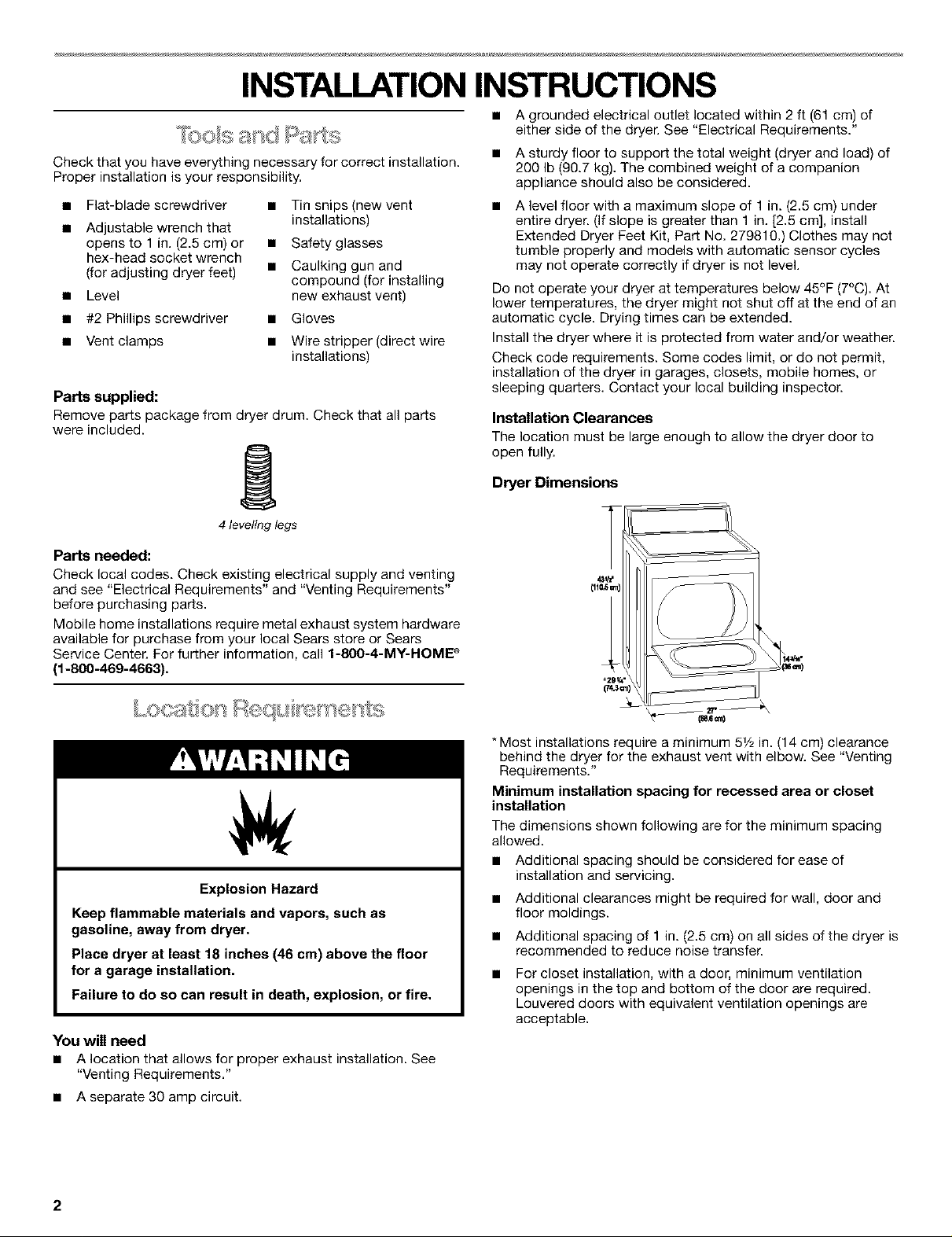
Installation Clearances
The location must be large enough to allow the dryer door to
open fully.
Dryer Dimensions
Parts needed:
Check local codes. Check existing electrical supply and venting
and see "Electrical Requirements" and "Venting Requirements"
before purchasing parts.
Mobile home installations require metal exhaust system hardware
available for purchase from your local Sears store or Sears
Service Center. For further information, call 1-8OO-4-MY-HOME _
(1-800-469-4663).
Explosion Hazard
Keep flammable materials and vapors, such as
gasoline, away from dryer.
Place dryer at least 18 inches (46 cm) above the floor
for a garage installation.
Failure to do so can result in death, explosion, or fire.
You will need
• A location that allows for proper exhaust installation. See
"Venting Requirements."
• A separate 30 amp circuit.
* Most installations require a minimum 5V2in. (14 cm) clearance
behind the dryer for the exhaust vent with elbow. See "Venting
Requirements."
Minimum installation spacing for recessed area or closet
installation
The dimensions shown following are for the minimum spacing
allowed.
• Additional spacing should be considered for ease of
installation and servicing.
Additional clearances might be required for wall, door and
floor moldings.
Additional spacing of 1 in. (2.5 cm) on all sides of the dryer is
recommended to reduce noise transfer.
For closet installation, with a door, minimum ventilation
openings in the top and bottom of the door are required.
Louvered doors with equivalent ventilation openings are
acceptable.
2
• Companion appliance spacing should also be considered.
'_'3"
olo [_ ,m)
JL
t,, -_1
I_ _" -_1I*-t" -_1t"I_ 2,,¢_t,,_'1<-
(z.S_)
Mobile Home-Additional Installation Requirements
This dryer is suitable for mobile home installations.
The installation must conform to the Manufactured Home
Construction and Safety Standard, Title 24 CFR, Part 3280
(formerly the Federal Standard for Mobile Home Construction
and Safety, Title 24, HUD Part 280).
Mobile home installations require:
• Metal exhaust system hardware which is available for
(eu=.) (zs=.) (_cm) (74.30_}(14=_)
1. Recessed area
2, Side view - closet or confined area
3. Closet door with vents
purchase from your dealer.
Special provisions must be made in mobile homes to
introduce outside air into the dryer. The opening (such as a
nearby window) should be at least twice as large as the dryer
exhaust opening.
_m
24. z
r_3"
[7.s=n)
2 3
It is your responsibility
• To contact a qualified electrical installer.
• To be sure that the electrical connection is adequate and in
conformance with the National Electrical Code, ANSI/NFPA
70-latest edition and all local codes and ordinances.
A copy of the above code standards can be obtained from:
National Fire Protection Association, Batterymarch Park,
Quincy, MA 02269.
• To supply the required 3 or 4 wire, single phase, 120/240-volt,
60-Hz., AC-only electrical supply (or 3 or 4 wire, 120/208-volt
electrical supply, if specified on the serial/rating plate) on a
separate 30-amp circuit, fused on both sides of the line. A
time-delay fuse or circuit breaker is recommended. Connect
to an individual branch circuit. Do not have a fuse in the
neutral or grounding circuit.
• Do not use an extension cord.
• If codes permit and a separate ground wire is used, it is
recommended that a qualified electrician determine that the
ground path is adequate.
Electrical Connection
To properly install your dryer, you must determine the type of
electrical connection you will be using and follow the instructions
provided for it here.
• If local codes do not permit the connection of a cabinet
ground connector to the neutral wire, see "Optional 3-wire
connection" section.
• This dryer is manufactured with a 3-wire, cabinet-ground
conductor connected to the NEUTRAL (white or center wire)
of the wiring harness at the terminal block.
• Use a 4-wire conductor cord when the dryer is installed in a
mobile home or an area where local codes do not permit
grounding through the neutral.
If using a power supply cord:
Use a UL approved power supply cord kit marked for use with
clothes dryers. The kit should contain:
• A UL approved 30 amp power supply cord, rated 120/240 volt
minimum. The cord should be type SRD or SRDT and be at
least 4 ft (1.22 m) long. The wires that connect to the dryer must
end in ring terminals or spade terminals with upturned ends.
• A UL approved strain relief.
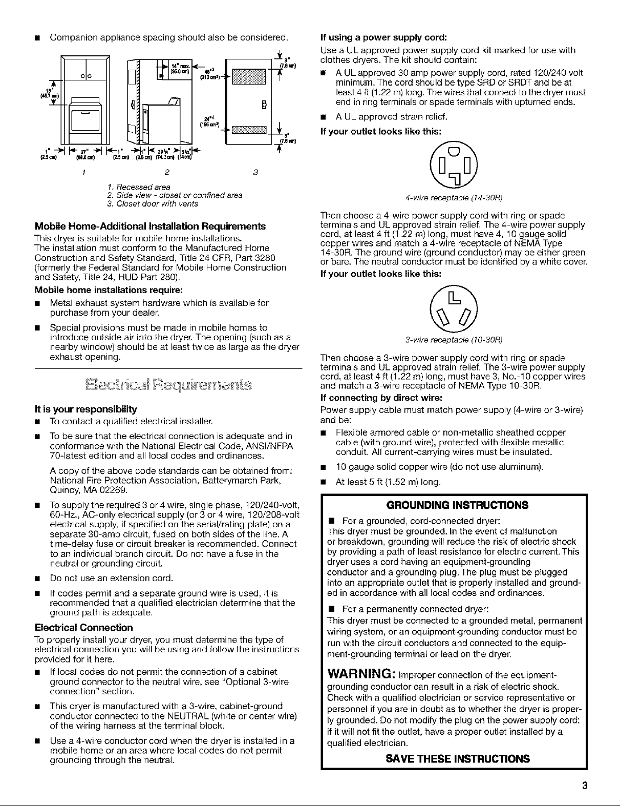
If your outlet looks like this:
©
4-wire receptacle (14-30R)
Then choose a 4-wire power supply cord with ring or spade
terminals and UL approved strain relief. The 4-wire power supply
cord, at least 4 ft (1.22 m) long, must have 4, 10 gauge solid
copper wires and match a 4-wire receptacle of NEMA Type
14-30R. The ground wire (ground conductor) may be either green
or bare. The neutral conductor must be identified by a white cover.
If your outlet looks like this:
©
3-wire receptacle (10-30R)
Then choose a 3-wire power supply cord with ring or spade
terminals and UL approved strain relief. The 3-wire power supply
cord, at least 4 ft (1.22 m) long, must have 3, No.-10 copper wires
and match a 3-wire receptacle of NEMA Type 10-30R.
If connecting by direct wire:
Power supply cable must match power supply (4-wire or 3-wire)
and be:
• Flexible armored cable or non-metallic sheathed copper
cable (with ground wire), protected with flexible metallic
conduit. All current-carrying wires must be insulated.
• 10 gauge solid copper wire (do not use aluminum).
• At least 5 ft (1.52 m) long.
GROUNDING INSTRUCTIONS
• For a grounded, cord-connected dryer:
This dryer must be grounded. In the event of malfunction
or breakdown, grounding will reduce the risk of electric shock
by providing a path of least resistance for electric current. This
dryer uses a cord having an equipment-grounding
conductor and a grounding plug. The plug must be plugged
into an appropriate outlet that is properly installed and ground-
ed in accordance with all local codes and ordinances.
• For a permanently connected dryer:
This dryer must be connected to a grounded metal, permanent
wtring system, or an equipment-grounding conductor must be
run with the circuit conductors and connected to the equip-
ment-grounding terminal or lead on the dryer.
WARNING: Improper connection of the equipment-
grounding conductor can result in a risk of electric shock.
;heck with a qualified electrician or service representative or
)ersonnel if you are in doubt as to whether the dryer is proper-
grounded. Do not modify the plug on the power supply cord:
if it will not fit the outlet, have a proper outlet installed by a
qualified electrician.
SAVE THESE INSTRUCTIONS
PowerSupplyCord DirectWire
FireHazard
Useanew UL approved 30 amp power supply cord.
Use a UL approved strain relief.
Disconnect power before making electrical connections.
Connect neutral wire (white or center wire) to center
terminal (silver).
Ground wire (green or bare wire) must be connected to
green ground connector.
Connect remaining 2 supply wires to remaining
2 terminals (gold).
Securely tighten all electrical connections.
Failure to do so can result in death, fire, or
electrical shock.
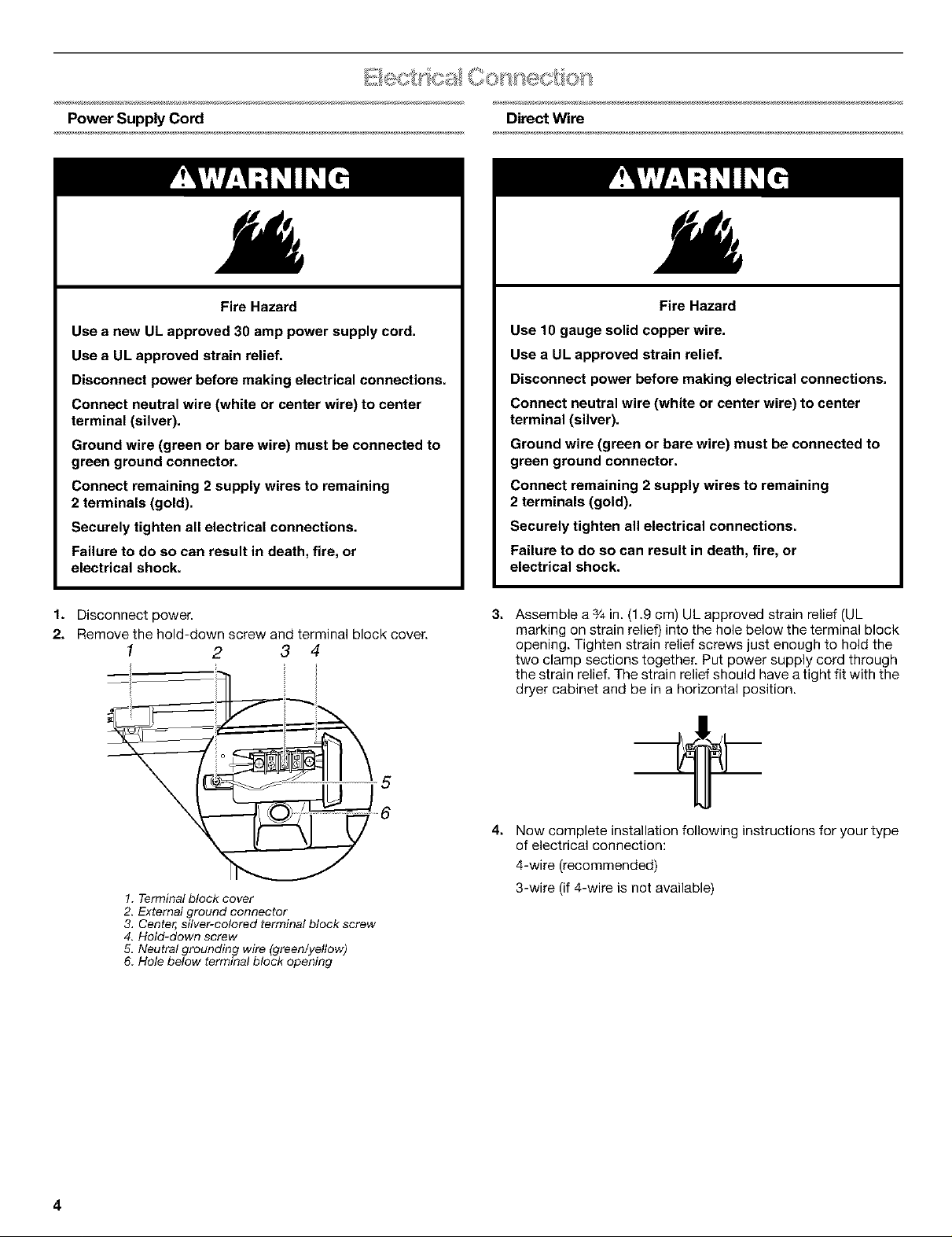
1. Disconnect power.
2. Remove the hold-down screw and terminal block cover.
1 2 3 4
Fire Hazard
Use 10 gauge solid copper wire.
Use a UL approved strain relief.
Disconnect power before making electrical connections.
Connect neutral wire (white or center wire) to center
terminal (silver).
Ground wire (green or bare wire) must be connected to
green ground connector.
Connect remaining 2 supply wires to remaining
2 terminals (gold).
Securely tighten all electrical connections.
Failure to do so can result in death, fire, or
electrical shock.
31
Assemble a s/4in. (1,9 cm) UL approved strain relief (UL
marking on strain relief) into the hole below the terminal block
opening. Tighten strain relief screws just enough to hold the
two clamp sections together. Put power supply cord through
the strain relief, The strain relief should have a tight fit with the
dryer cabinet and be in a horizontal position.
5
6
41
Now complete installation following instructions for your type
of electrical connection:
4-wire (recommended)
1. Terminal block cover
2. External ground connector
3, Center, silver-colored terminal block screw
4. Hold-down screw
5. Neutral grounding wire (green/yellow)
6. Hole below terminal block opening
4
3-wire (if 4-wire is not available)
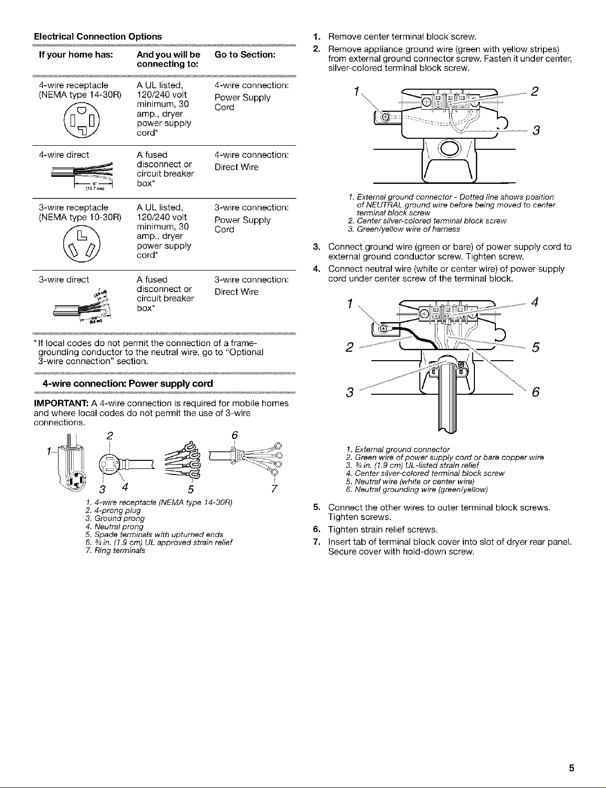
Electrical Connection Options 1.
If your home has: And you will be Go to Section:
connecting to:
Remove center terminal block screw.
Remove appliance ground wire (green with yellow stripes)
from external ground connector screw. Fasten it under center,
silver-colored terminal block screw.
4-wire receptacle A UL listed, 4-wire connection:
(NEMA type 14-30R) 120/240 volt Power Supply
amp., dryer
(_ minimum, 30 Cord
power supply
cord*
4-wire direct A fused 4-wire connection:
disconnect or Direct Wire
circuit breaker
box*
3-wire receptacle A UL listed, 3-wire connection:
(NEMA type 10-30R) 120/240 volt Power Supply
amp., dryer
power supply
minimum, 30 Cord
cord*
3-wire direct A fused 3-wire connection:
disconnect or Direct Wire
circuit breaker
box*
* If local codes do not permit the connection of a frame-
grounding conductor to the neutral wire, go to "Optional
3-wire connection" section.
2
3
1. External ground connector - Dotted line shows position
of NEUTRAL ground wire before being moved to center
terminal block screw
2, Center silver-colored terminal block screw
3. Green/yellow wire of harness
3. Connect ground wire (green or bare) of power supply cord to
external ground conductor screw. Tighten screw.
4. Connect neutral wire (white or center wire) of power supply
cord under center screw of the terminal block.
2 \\11 .................5
4-wire connection: Power supply cord
IMPORTANT: A 4-wire connection is required for mobile homes
and where local codes do not permit the use of 3-wire
connections.
2 6
4 5 7
3
1, 4-wire receptacle (NEMA type 14-30R)
2. 4-prong plug
3. Ground prong
4. Neutral prong
5. Spade terminals with upturned ends
6. ¾ in. (1.9 cm) UL approved strain relief
7. Ring terminals
,,,,, 6
1. External ground connector
2. Green wire of power supply cord or bare copper wire
3. ¾ in (1.9 cm) UL-listed strain relief
4. Center silver-colored terminal block screw
5, Neutral wire (white or center wire)
6. Neutral grounding wire (green/yellow)
5. Connect the other wires to outer terminal block screws.
Tighten screws.
6. Tighten strain relief screws.
7. Insert tab of terminal block cover into slot of dryer rear panel.
Secure cover with hold-down screw.
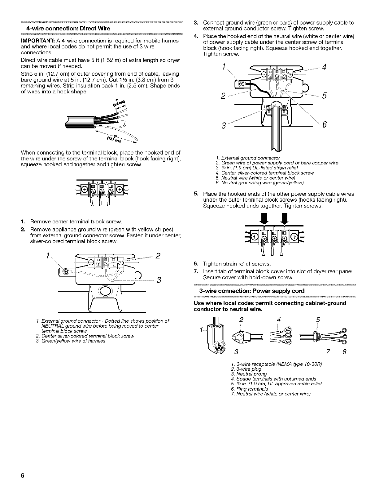
4-wire connection: Direct Wire
IMPORTANT: A 4-wire connection is required for mobile homes
and where local codes do not permit the use of 3 wire
connections.
Direct wire cable must have 5 ft (1.52 m) of extra length so dryer
can be moved if needed.
Strip 5 in. (12.7 cm) of outer covering from end of cable, leaving
bare ground wire at 5 in. (12.7 cm). Cut 11/2in. (3.8 cm) from 3
remaining wires. Strip insulation back 1 in. (2.5 cm). Shape ends
of wires into a hook shape.
3. Connect ground wire (green or bare) of power supply cable to
external ground conductor screw. Tighten screw.
4. Placethehookedendoftheneutralwire(whiteorcenterwire)
of power supply cable under the center screw of terminal
block (hook facing right). Squeeze hooked end together.
Tighten screw.
..................... 4
....................
When connecting to the terminal block, place the hooked end of
the wire under the screw of the terminal block (hook facing right),
squeeze hooked end together and tighten screw.
1. Remove center terminal block screw.
2. Remove appliance ground wire (green with yellow stripes)
from external ground connector screw. Fasten it under center,
silver-colored terminal block screw.
2
1.External ground connector - Dotted line shows position of
NEUTRAL ground wire before being moved to center
terminal block screw
2. Center silver-colored terminal block screw
3. Green/yellow wire of harness
1, External ground connector
2. Green wire of power supply cord or bare copper wire
3. ¾in, (1.9 cm) UL-tisted strain relief
4. Center silver-colored terminal block screw
5. Neutral wire (white or center wire)
6. Neutral grounding wire (green/yellow)
5.
Place the hooked ends of the other power supply cable wires
under the outer terminal block screws (hooks facing right).
Squeeze hooked ends together. Tighten screws.
!! !!
6. Tighten strain relief screws.
7. Insert tab of terminal block cover into slot of dryer rear paneL
Secure cover with hold-down screw.
3-wire connection: Power supply cord
Use where local codes permit connecting cabinet-ground
conductor to neutral wire.
2 4 5
1.3-wire receptacle (NEMA type 10-30R)
2. 3-wire plug
3. Neutral prong
4. Spade terminals with upturned ends
5, ¾ in (1.9 cm) UL approved strain relief
6. Ring terminals
7. Neutral wire (white or center wire)
6
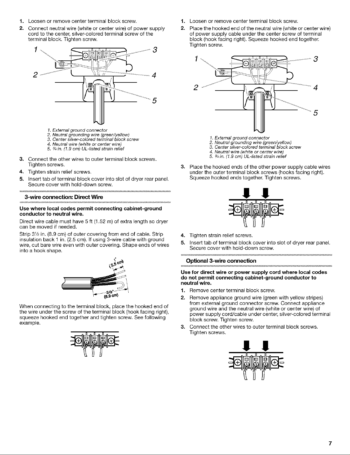
1. Loosen or remove center terminal block screw.
2. Connect neutral wire (white or center wire) of power supply
cord to the center, silver-colored terminal screw of the
terminal block. Tighten screw.
1
1*
Loosen or remove center terminal block screw.
2.
Place the hooked end of the neutral wire (white or center wire)
of power supply cable under the center screw of terminal
block (hook facing right). Squeeze hooked end together.
Tighten screw.
3
2
4
5
1, External ground connector
2. Neutral grounding wire (green/yellow)
3. Center silver-colored terminal block screw
4. Neutral wire (white or center wire)
5. ¾in. (1.9 crn) UL-listed strain relief
3. Connect the other wires to outer terminal block screws.
Tighten screws.
4. Tighten strain relief screws.
5. Insert tab of terminal block cover into slot of dryer rear panel.
Secure cover with hold-down screw.
3-wire connection: Direct Wire
Use where local codes permit connecting cabinet-ground
conductor to neutral wire.
Direct wire cable must have 5 ft (1.52 m) of extra length so dryer
can be moved if needed.
Strip 3V2in. (8.9 cm) of outer covering from end of cable. Strip
insulation back 1 in. (2.5 cm). If using 3-wire cable with ground
wire, cut bare wire even with outer covering. Shape ends of wires
into a hook shape.
2
4
5
1, External ground connector
2. Neutral grounding wire (green/yellow)
3. Center silver-colored terminal block screw
4. Neutral wire (white or center wire)
5. _ in. (1.9 cm) UL-listed strain relief
3.
Place the hooked ends of the other power supply cable wires
under the outer terminal block screws (hooks facing right).
Squeeze hooked ends together. Tighten screws.
!! !!
4. Tighten strain relief screws.
5. Insert tab of terminal block cover into slot of dryer rear panel.
Secure cover with hold-down screw.
Optional 3-wire connection
When connecting to the terminal block, place the hooked end of
the wire under the screw of the terminal block (hook facing right),
squeeze hooked end together and tighten screw. See following
example.
Use for direct wire or power supply cord where local codes
do not permit connecting cabinet-ground conductor to
neutral wire.
1. Remove center terminal block screw.
2. Remove appliance ground wire (green with yellow stripes)
from external ground connector screw. Connect appliance
ground wire and the neutral wire (white or center wire) of
power supply cord/cable under center, silver-colored terminal
block screw. Tighten screw.
3. Connect the other wires to outer terminal block screws.
Tighten screws.
!! !!
7
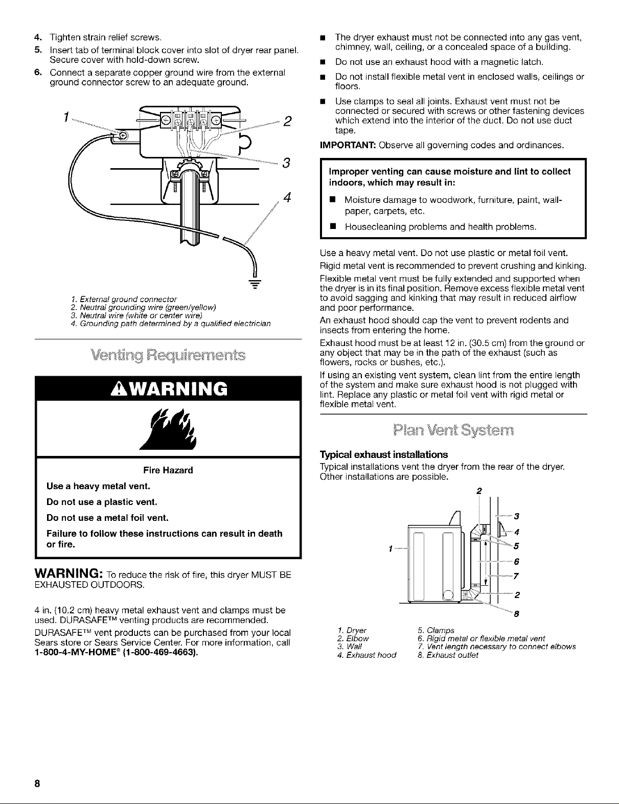
4. Tighten strain relief screws.
5. Insert tab of terminal block cover into slot of dryer rear panel.
Secure cover with hold-down screw.
6. Connect a separate copper ground wire from the external
ground connector screw to an adequate ground.
2
3
4
1, External ground connector
2. Neutral grounding wire (green/yellow)
3. Neutral wire (white or center wire)
4. Grounding path determined by a qualified electrician
• The dryer exhaust must not be connected into any gas vent,
chimney, wall, ceiling, or a concealed space of a building.
• Do not use an exhaust hood with a magnetic latch.
• Do not install flexible metal vent in enclosed walls, ceilings or
floors.
Use clamps to seal all joints. Exhaust vent must not be
connected or secured with screws or other fastening devices
which extend into the interior of the duct. Do not use duct
tape.
IMPORTANT: Observe all governing codes and ordinances.
Improper venting can cause moisture and lint to collect
indoors, which may result in:
• Moisture damage to woodwork, furniture, paint, wall-
paper, carpets, etc.
• Housecleaning problems and health problems.
Use a heavy metal vent. Do not use plastic or metal foil vent.
Rigid metal vent is recommended to prevent crushing and kinking.
Flexible metal vent must be fully extended and supported when
the dryer is in its final position. Remove excess flexible metal vent
to avoid sagging and kinking that may result in reduced airflow
and poor performance.
An exhaust hood should cap the vent to prevent rodents and
insects from entering the home.
Exhaust hood must be at least 12 in. (30.5 cm) from the ground or
any object that may be in the path of the exhaust (such as
flowers, rocks or bushes, etc.).
If using an existing vent system, clean lint from the entire length
of the system and make sure exhaust hood is not plugged with
lint. Replace any plastic or metal foil vent with rigid metal or
flexible metal vent.
Fire Hazard
Use a heavy metal vent.
Do not use a plastic vent.
Do not use a metal foil vent.
Failure to follow these instructions can result in death
or fire.
WARNING: To reduce the risk of fire, this dryer MUST BE
EXHAUSTED OUTDOORS.
4 in. (10.2 cm) heavy metal exhaust vent and clamps must be
used. DURASAFE TM venting products are recommended.
DURASAFF Mvent products can be purchased from your local
Sears store or Sears Service Center. For more information, call
1-800-4-MY-HOME ®(1-800-469-4663).
Typical exhaust installations
Typical installations vent the dryer from the rear of the dryer.
Other installations are possible.
2
J!:
'........... rlTil]2;
1, Dryer
2. Elbow
3. Watt
4. Exhaust hood
5. Clamps
6. Rigid metal or flexible metal vent
7. Vent length necessary to connect elbows
8. Exhaust outlet
8
 Loading...