


S/M No. RFP7102000
REFRIGERATOR
SERVICE MANUAL
CAUTION
BEFORE SERVICING THE UNIT,
READ THE SAFETY PRECAUTIONS IN THIS MANUAL.
TYPE |
MODEL |
FACTORY MODEL |
Color |
|
|
|
|
|
|
|
111.75505020 |
RFP71KETJ4E00-UEDB |
STAINLESS |
|
|
|
|
|
|
|
111.75507020 |
RFP71KEBJ4E00-UEDB |
BLACK |
|
STEP |
STAINLESS |
|||
|
|
|||
UP |
|
|
|
|
|
|
|
|
|
|
|
|
|
TYPE |
MODEL |
FACTORY MODEL |
Color |
|
|
|
|
|
|
|
111.75035020 |
RFP71KDTJ4E00-UECB |
STAINLESS |
|
|
|
|
|
|
|
111.75032020 |
RFP71KDWC4E00-UECB |
WHITE |
|
OPP |
|
|
|
|
111.75039020 |
RFP71KDBC4E00-UECB |
BLACK |
||
|
||||
|
|
|
|
|
|
|
|
|
√ Caution
In this manual, some parts can be changed for improving their performance without notice. So, If you need the latest parts information, please visit and refer to PPL (Parts Price List) in Service Information Center.(http://webportal.winiadaewoo.com/sic)
Mar.2020

Content
1. |
Warnings and |
…………………........ 4 |
|
|
Precautions for Safety |
|
|
2. |
Specifications ……………………..…........... |
5 |
|
3. |
Sensor / Voltage |
………………...…..... |
7 |
4.External Dimensions ………………...…..... 9
5.Features ……….…………………..…........... 10
6.Flow Diagram
6-1. Cold Air Flow……….……………........... 14
6-2. Water Flow ……….……………........... 15
6-3. Refrigerant Flow ……….…………........ 16 and Welding Point
7.Wiring Diagram ……….……………............ 17
8.Operation and Function
8-1. How to Use Control Panel ……….….... 24
8-2. Service Mode and Error Display ……... 26
8-3. Compressor, Fan & Damper ……….... 28
8-4. Defrost Mode ……………………….….. 28
8-5. |
Forced Defrost Mode ………………….. 28 |
8-6. |
Icemaker in the Icemaker Room ….. 29 |
8-7. |
Icemaker in the Freezer |
………….... 32 |
8-8. |
Pantry Drawer ………………………….. 34 |
|
8-9. |
Dispenser Water/Ice Lever |
……..… 34 |
8-10. |
Buzzer or Alarm ………………….…. 34 |
8-11. |
Compensation of Refrigerator |
|
Sensor On/Off Temp …………….…. 35 |
|
9. How to Service |
|
|
9-1. |
Faulty Start |
…... 36 |
|
(F/R lights Off, F-PCB Power Off) |
|
9-2. |
Freezing Failure |
……..…... 37 |
|
(Foods are not frozen/cold.) |
|
9-3. |
Ice Formation on F-Louver |
……..…... 38 |
9-4. |
Disconnection / Breaking |
……..…... 39 |
of Freezer Lights Ass’y
9-5. Disconnection / Breaking |
……..…... 40 |
|||
of Refrigerator Lights Ass’y |
||||
9-6. |
Refrigeration Failure |
.... 41 |
||
|
(Foods does not get cool or cold soon.) |
|||
9-7. |
Dews on Refrigerator Compartment ... 42 |
|||
9-8. |
Comp. Operation Noise |
……………... 43 |
||
9-9. |
Refrigerant Flow Sound |
……………... 44 |
||
9-10. |
Fan Noise |
………………….………... 45 |
||
9-11. |
Pipe Noise |
………………….……... 46 |
||
9-12. Door opening alarm continues ……. 47 though the door is closed.
10. Cooling Cycle Heavy Repair
10-1. Summary of Heavy Repair ………….. |
48 |
||
10-2. |
Precautions During Heavy Repair |
.... |
49 |
10-3. |
Practical Work for Heavy Repair |
.... |
50 |
10-4. Standard Regulations …………….... |
52 |
||
for Heavy Repair |
|
|
|
11. Disassemble/Assemble Procedures
11-1. Holder Water Filter Ass’y …………... 53
11-2. Water Tank and |
………….….. |
54 |
Cover Vegetable Ass’y |
|
|
11-3. Hose Ice Maker Tube Ass’y ……….. |
56 |
|
11-4. Icemaker …………………………….. 57
11-8. Fixture Geared Motor |
……………….. 58 |
||
11-6. |
Pantry Drawer Cover |
…………...….. 59 |
|
and Cover Multi-duct Ass’y |
|
||
11-7. |
Refrigerator Sensor, |
…………...….. 60 |
|
|
Pantry Drawer Sensor, |
|
|
|
Dampers in Cover multi-Duct Ass’y |
|
|
11-8. |
Control Panel PCB and Wires …..... |
61 |
|
|
in Pantry Drawer Cover Ass’y |
|
|
11-9. |
Freezer Louver Ass’y |
…................. |
62 |
11-10. Freezer Sensor, |
…................. |
63 |
|
|
F Fan and Fan Motor |
|
|

Content
|
|
|
|
|
|
|
|
|
|
|
|
12. Service Part List |
|
||
11-11. Refrigerator Fan |
…………... 64 |
12-1. |
Cabinet |
……………….………..….. 74 |
|||
and Fan motor in Freezer |
|
|
|||||
|
|
|
|
|
|
||
11-12. Freezer Defrost Sensor |
|
|
12-2. Machine Room |
………………..….. 75 |
|||
……..... 65 |
|
|
|
|
|||
and Heater in the Eva Ass’y |
|
12-3. F-Room |
……………………..…..….. 76 |
||||
11-13. |
Sensor in Ice Maker Eva Ass’y |
..... 66 |
12-4. |
R-Room |
……………………..…..….. 77 |
||
11-13. |
Heater in Ice Maker Eva Ass’y |
..... 67 |
12-5. |
F-Door & Handles |
……………...….. 78 |
||
11-14. |
Condenser Fan Motor …………..... 68 |
12-6. |
R-Door |
…………………………...….. 79 |
|||
|
in Machine Room |
|
|
|
|
|
|
11-15. |
Freezer and Refrigerator |
………..... 69 |
|
|
|
|
|
|
Door Switch |
|
|
|
|
|
|
11-16. Front Control Panel in Dispenser …. 70
11-17. Dispenser Lever Ass’y …………..…. 71
11-18. Mullion Bar Ass’y ………………..…. 72
11-19. Interior F/R Lamp ………………..…. 73
Refer to user manual for installation
Document History
Version |
Date |
Author |
Description |
|
(S/M No.) |
||||
|
|
|
||
|
|
|
|
|
RFP7122000 |
2020.3/26 |
Lucas |
Register a document. |
|
|
|
|
|

1. Warnings and Precautions for Safety
Please observe the following safety precautions in order to use safely and correctly the refrigerator and to prevent accident and danger during repair.
1.Be care of an electric shock. Disconnect power cord from wall outlet and wait for more than three minutes before replacing PCB parts.
Shut off the power whenever replacing and repairing electric components.
2.When connecting power cord, please wait for more than five minutes after power cord was disconnected from the wall outlet.
3.Please check if the power plug is pressed down by the refrigerator against the wall. If the power plug was damaged, it may cause fire or electric shock.
4.If the wall outlet is over loaded, it may cause fire.
Please use its own individual electrical outlet for the refrigerator.
5.Please make sure the outlet is properly earthed, particularly in wet or damp area.
6.Use standard electrical components when replacing them.
7.Make sure the hook is correctly engaged.
Remove dust and foreign materials from the housing and connecting parts.
8.Do not fray, damage, machine, heavily bend, pull out or twist the power cord.
9.Please check the evidence of moisture intrusion in the electrical components. Replace the parts or mask it with insulation tapes if moisture intrusion was confirmed.
10.Do not touch the icemaker with hands or tools to confirm the operation of geared motor.
11.Do not let the customers repair, disassemble and reconstruct the refrigerator for themselves.
It may cause accident, electric shock, or fire.
12.Do not store flammable materials such as ether, benzene, alcohol, chemicals, gas,
or medicine in the refrigerator.
13.Do not put flower vase, cup, cosmetics, chemicals, etc., or container with full of water on the top of the refrigerator.
14.Do not put glass bottles with full of water into the freezer.
The contents shall freeze and break the glass bottles.
15.When you scrap the refrigerator, please disconnect the door gasket first and scrap it where children are not accessible.
! |
WARNING |
To avoid risk of electrical shock that can cause death or severe personal injury, |
4 / 79 |
disconnect unit from power before servicing unless tests require power. |

2. Specifications
|
|
|
|
|
|
|
|
|
|
|
|
|
|
|
|
|
|
|
|
Model Name |
111.7550****, 111.7503**** |
|
|
|
|
|
|
|
|
|
|
|
|
|
Factory Model Name |
RFP71KE******-****, RFP71KD******-**** |
|
||
|
|
|
|
|
|
|
|
|
|
Volume |
|
Total |
25.5 |
|
|
|
|
|
|
|
|
||
|
AHAM 2008 |
|
Freezer |
7.8 |
|
||
|
|
(Cu ft.) |
|
|
|
|
|
|
|
|
Refrigerator |
17.7 |
|
||
|
|
|
|
|
|
||
|
|
|
|
|
|
|
|
|
|
|
External Dimension |
35.98 “ x 69.81” x 33.79” (w/o Handle) |
|
||
|
|
|
(Width * Depth * Height) |
|
|||
|
|
|
|
|
|||
|
|
|
|
Rated Voltage |
115~120V (60Hz) |
|
|
|
|
|
|
|
|
|
|
|
|
Weight |
|
Net |
138 |
|
|
|
|
|
|
|
|
||
|
|
(Kg) |
|
Gross (w/ Package) |
151 |
|
|
|
|
|
|
|
|
||
|
|
|
|
|
|
|
|
|
|
|
|
|
Model |
NC4EVA5ALM (SAMSUNG) |
|
|
|
|
|
|
|
|
|
|
|
|
|
|
Motor Type |
Inverter Driver |
|
|
|
|
|
|
|
|
|
|
|
|
|
|
Motor Protection |
- |
|
|
|
|
|
|
|
|
|
|
|
|
Comp |
|
Running Capacitor |
- |
|
|
C |
|
|
|
|
|
|
|
|
|
|
Starting Device Type |
Inverter Driver |
|
|
|
O |
|
|
|
|
||
|
|
|
|
|
|
|
|
|
O |
|
|
|
Starting Device |
- |
|
|
L |
|
|
|
|
||
|
|
|
|
|
|
|
|
|
I |
|
|
|
Controller Unit (Inverter) |
‘- |
|
|
N |
|
|
|
|
||
|
|
|
|
|
|
|
|
|
G |
|
Refrigerant |
R600a |
|
||
|
|
|
|
||||
|
|
|
|
|
|
|
|
|
|
|
Quantity |
77g |
|
||
|
|
|
|
|
|
||
|
|
|
Evaporator |
Fin Type |
|
||
|
|
|
|
|
|
||
|
|
|
Condenser |
Fan Cooling System |
|
||
|
|
|
|
|
|
|
|
|
|
|
Dryer |
|
|
Molecular Sieve XH-9 |
|
|
|
|
|
|
|
|
|
|
|
|
|
|
Freezer |
On Right Front Side of Freezer Wall |
|
|
Door Switch |
|
|
|
|
||
|
|
Refrigerator |
In Top Cover Hinge |
|
|||
|
|
|
|
|
|
||
|
|
|
|
|
|
|
|
|
|
|
|
|
Freezer |
5-LED |
|
|
|
Lamp |
|
|
|
|
|
|
|
|
Refrigerator |
18-LED |
|
||
|
|
|
|
|
|
||
|
|
|
|
|
|
|
|
! |
WARNING |
To avoid risk of electrical shock that can cause death or severe personal injury, |
5 / 79 |
disconnect unit from power before servicing unless tests require power. |

2. Specifications
(continued)
|
Model Name |
111.7550****, 111.7503**** |
||
|
|
|
|
|
|
Factory Model Name |
RFP71KE******-**** |
RFP71KD******-**** |
|
|
|
|
|
|
|
|
Defrost |
In Evaporator Assembly, |
|
|
|
In Icemaker Evaporator Assembly |
||
|
|
|
|
|
|
|
Freezer |
In Louver Assembly |
|
|
|
|
|
|
|
|
Refrigerator |
In Multi Flow Duct Assembly |
|
|
|
|
|
|
Sensor |
|
RT |
Between Top Cabinet and Top |
|
|
|
Cover Hinge |
||
|
|
|
|
|
|
|
Icemaker Room Temp. |
In Fixture Geared Motor Assembly |
|
|
|
|
|
|
|
|
Pantry Drawer Temp. |
In Multi Flow Duct Assembly |
|
|
|
|
|
|
|
|
Water Flow |
In Valve Water Assembly |
|
|
|
|
|
|
|
|
Freezer Eva. |
AC120V / 380W / 35 ~ 41Ω / |
|
|
|
Sheath |
||
|
|
|
|
|
|
|
Icemaker Eva. |
AC120V / 40W / 360Ω / Sheath |
|
|
|
|
|
|
|
|
Division |
AC115V / 6W / 2028 ~ 2380Ω |
|
|
|
|
|
|
Heater |
|
Water Tank |
N/A |
|
|
|
|
|
|
|
|
Dispenser Ice Flap |
N/A |
|
|
|
|
|
|
|
|
R Motor behind Eva |
N/A |
|
|
|
|
|
|
|
|
Icemaker Water Hose |
No Service Part |
|
|
|
|
|
|
|
|
Icemaker Room Heater |
N/A |
|
|
|
|
|
|
|
Fuse Temp (Defrost) |
AC250V , 10A , 77 |
|
|
|
|
|
|
|
|
|
Freezer Fan |
DC12V / DREP9020LJ |
|
|
|
|
|
|
|
|
Refrigerator Fan |
DC12V / DREP9020LL |
|
|
|
|
|
|
|
|
Condenser Fan |
DC13V / D4612AAA28 |
|
|
|
|
|
|
Motor |
|
Dispenser Ice Shut |
DC 12V / STAB040D01 |
|
|
|
|
|
|
|
|
Ice Crusher |
120V / 60Hz / ISG-3240DED |
|
|
|
|
|
|
|
|
Ice Type Selector |
DC12V / STAB04D01 |
|
|
|
|
|
|
|
|
Ice Maker Fan |
DC12V / ODM-016F-57A |
|
|
|
|
|
|
|
|
Damper |
DC12V / DU24-113 / 1pcs |
N/A |
|
|
|
|
|
! |
WARNING |
To avoid risk of electrical shock that can cause death or severe personal injury, |
6 / 79 |
disconnect unit from power before servicing unless tests require power. |
3. Sensor / Voltage
(Table of sensor resistance and measured voltage)
|
|
|
|
|
R, Pantry, Ice Maker, F Defrost, R Defrost, I/M Defrost, RT SENSOR |
|
|
||||
|
|
Temp( ) |
Temp( ) |
Resistance(kΩ) |
DC Volts |
Temp( ) |
Temp( ) |
Resistance(kΩ) |
DC Volts |
|
|
|
|
-22.0 |
|
-30.0 |
129.30 |
4.02 |
32.9 |
0.5 |
29.34 |
2.42 |
|
|
|
-21.1 |
|
-29.5 |
125.90 |
4.00 |
33.8 |
1.0 |
28.71 |
2.39 |
|
|
|
-20.2 |
|
-29.0 |
122.50 |
3.98 |
34.7 |
1.5 |
28.08 |
2.36 |
|
|
|
-19.3 |
|
-28.5 |
119.30 |
3.96 |
35.6 |
2.0 |
27.47 |
2.33 |
|
|
|
-18.4 |
|
-28.0 |
116.20 |
3.94 |
36.5 |
2.5 |
26.88 |
2.31 |
|
|
|
-17.5 |
|
-27.5 |
113.20 |
3.91 |
37.4 |
3.0 |
26.30 |
2.28 |
|
|
|
-16.6 |
|
-27.0 |
110.20 |
3.89 |
38.3 |
3.5 |
25.74 |
2.25 |
|
|
|
-15.7 |
|
-26.5 |
107.40 |
3.87 |
39.2 |
4.0 |
25.19 |
2.23 |
|
|
|
-14.8 |
|
-26.0 |
101.60 |
3.82 |
40.1 |
4.5 |
24.65 |
2.20 |
|
|
|
-13.9 |
|
-25.5 |
101.90 |
3.82 |
41.0 |
5.0 |
24.13 |
2.17 |
|
|
|
-13.0 |
|
-25.0 |
99.30 |
3.80 |
41.9 |
5.5 |
23.62 |
2.15 |
|
|
|
-12.1 |
|
-24.5 |
96.70 |
3.77 |
42.8 |
6.0 |
23.12 |
2.12 |
|
|
|
-11.2 |
|
-24.0 |
94.30 |
3.75 |
43.7 |
6.5 |
22.63 |
2.09 |
|
|
|
-10.3 |
|
-23.5 |
91.90 |
3.73 |
44.6 |
7.0 |
22.15 |
2.07 |
|
|
|
-9.4 |
|
-23.0 |
89.60 |
3.70 |
45.5 |
7.5 |
21.69 |
2.04 |
|
|
|
-8.5 |
|
-22.5 |
87.30 |
3.68 |
46.4 |
8.0 |
21.24 |
2.02 |
|
|
|
-7.6 |
|
-22.0 |
85.10 |
3.65 |
47.3 |
8.5 |
20.80 |
1.99 |
|
|
|
-6.7 |
|
-21.5 |
83.00 |
3.63 |
48.2 |
9.0 |
20.36 |
1.97 |
|
|
|
-5.8 |
|
-21.0 |
80.90 |
3.60 |
49.1 |
9.5 |
19.94 |
1.94 |
|
|
|
-4.9 |
|
-20.5 |
78.90 |
3.58 |
50.0 |
10.0 |
19.53 |
1.92 |
|
|
|
-4.0 |
|
-20.0 |
76.90 |
3.55 |
50.9 |
10.5 |
19.13 |
1.89 |
|
|
|
-3.1 |
|
-19.5 |
75.00 |
3.52 |
51.8 |
11.0 |
18.74 |
1.87 |
|
|
|
-2.2 |
|
-19.0 |
78.20 |
3.57 |
52.7 |
11.5 |
18.35 |
1.84 |
|
|
|
-1.3 |
|
-18.5 |
71.40 |
3.47 |
53.6 |
12.0 |
17.98 |
1.82 |
|
|
|
-0.4 |
|
-18.0 |
69.60 |
3.45 |
54.5 |
12.5 |
17.61 |
1.80 |
|
|
|
0.5 |
|
-17.5 |
67.90 |
3.42 |
55.4 |
13.0 |
17.26 |
1.77 |
|
|
|
1.4 |
|
-17.0 |
66.30 |
3.39 |
56.3 |
13.5 |
16.91 |
1.75 |
|
|
|
2.3 |
|
-16.5 |
64.70 |
3.37 |
57.2 |
14.0 |
16.37 |
1.71 |
|
|
|
3.2 |
|
-16.0 |
63.10 |
3.34 |
58.1 |
14.5 |
16.26 |
1.71 |
|
|
|
4.1 |
|
-15.5 |
61.60 |
3.31 |
59.0 |
15.0 |
15.91 |
1.68 |
|
|
|
5.0 |
|
-15.0 |
60.10 |
3.28 |
59.9 |
15.5 |
15.59 |
1.66 |
|
|
|
5.9 |
|
-14.5 |
58.60 |
3.26 |
60.8 |
16.0 |
15.28 |
1.64 |
|
|
|
6.8 |
|
-14.0 |
57.20 |
3.23 |
61.7 |
16.5 |
14.98 |
1.61 |
|
|
|
7.7 |
|
-13.5 |
55.90 |
3.20 |
62.6 |
17.0 |
14.66 |
1.59 |
|
|
|
8.6 |
|
-13.0 |
54.60 |
3.17 |
63.5 |
17.5 |
14.39 |
1.57 |
|
|
|
9.5 |
|
-12.5 |
53.30 |
3.15 |
64.4 |
18.0 |
14.10 |
1.55 |
|
|
|
10.4 |
|
-12.0 |
52.00 |
3.12 |
65.3 |
18.5 |
13.83 |
1.53 |
|
|
|
11.3 |
|
-11.5 |
50.80 |
3.09 |
66.2 |
19.0 |
13.56 |
1.51 |
|
|
|
12.2 |
|
-11.0 |
49.60 |
3.06 |
67.1 |
19.5 |
13.29 |
1.49 |
|
|
|
13.1 |
|
-10.5 |
48.70 |
3.04 |
68.0 |
20.0 |
13.03 |
1.47 |
|
|
|
14.0 |
|
-10.0 |
47.30 |
3.01 |
68.9 |
20.5 |
12.78 |
1.45 |
|
|
|
14.9 |
|
-9.5 |
46.20 |
2.98 |
69.8 |
21.0 |
12.53 |
1.43 |
|
|
|
15.8 |
|
-9.0 |
45.10 |
2.95 |
70.7 |
21.5 |
12.29 |
1.41 |
|
|
|
16.7 |
|
-8.5 |
44.10 |
2.92 |
71.6 |
22.0 |
12.05 |
1.39 |
|
|
|
17.6 |
|
-8.0 |
43.10 |
2.89 |
72.5 |
22.5 |
11.82 |
1.37 |
|
|
|
18.5 |
|
-7.5 |
42.10 |
2.86 |
73.4 |
23.0 |
11.60 |
1.35 |
|
|
|
19.4 |
|
-7.0 |
41.10 |
2.83 |
74.3 |
23.5 |
11.37 |
1.33 |
|
|
|
20.3 |
|
-6.5 |
40.30 |
2.81 |
75.2 |
24.0 |
11.16 |
1.31 |
|
|
|
21.2 |
|
-6.0 |
39.30 |
2.78 |
76.1 |
24.5 |
10.95 |
1.29 |
|
|
|
22.1 |
|
-5.5 |
37.90 |
2.73 |
77.0 |
25.0 |
10.74 |
1.27 |
|
|
|
23.0 |
|
-5.0 |
37.50 |
2.72 |
77.9 |
25.5 |
10.54 |
1.26 |
|
|
|
23.9 |
|
-4.5 |
36.70 |
2.69 |
78.8 |
26.0 |
10.34 |
1.24 |
|
|
|
24.8 |
|
-4.0 |
35.80 |
2.66 |
79.7 |
26.5 |
10.14 |
1.22 |
|
|
|
25.7 |
|
-3.5 |
35.00 |
2.64 |
80.6 |
27.0 |
9.945 |
1.20 |
|
|
|
26.6 |
|
-3.0 |
34.30 |
2.61 |
81.5 |
27.5 |
9.768 |
1.19 |
|
|
|
27.5 |
|
-2.5 |
33.50 |
2.58 |
82.4 |
28.0 |
9.586 |
1.17 |
|
|
|
28.4 |
|
-2.0 |
32.70 |
2.55 |
83.3 |
28.5 |
9.408 |
1.15 |
|
|
|
29.3 |
|
-1.5 |
32.00 |
2.52 |
84.2 |
29.0 |
9.234 |
1.14 |
|
|
|
30.2 |
|
-1.0 |
31.30 |
2.50 |
85.1 |
29.5 |
9.063 |
1.12 |
|
|
|
31.1 |
|
-0.5 |
30.60 |
2.47 |
86.0 |
30.0 |
8.896 |
1.10 |
|
|
|
32.0 |
|
0.0 |
30.00 |
2.44 |
|
|
|
|
|
|
|
|
|
|
|
|
|
|
|
|
|
! |
WARNING |
To avoid risk of electrical shock that can cause death or severe personal injury, |
|
7 / 79 |
|||||||
disconnect unit from power before servicing unless tests require power. |
|
||||||||||
|
|
|
|
|
|
|
|
|
|
|
|

3. Sensor / Voltage
(Table of sensor resistance and measured voltage)
|
|
|
|
|
|
F Sensor |
|
|
|
|
|
|
|
Temp( ) |
Temp( ) |
Resistance(kΩ) |
DC Volts |
Temp( ) |
Temp( ) |
Resistance(kΩ) |
DC Volts |
|
|
|
|
-22.0 |
|
-30.0 |
39.652 |
3.04 |
32.9 |
0.5 |
7.692 |
1.16 |
|
|
|
-21.1 |
|
-29.5 |
38.495 |
3.01 |
33.8 |
1.0 |
7.508 |
1.14 |
|
|
|
-20.2 |
|
-29.0 |
37.375 |
2.97 |
34.7 |
1.5 |
7.328 |
1.12 |
|
|
|
-19.3 |
|
-28.5 |
36.291 |
2.94 |
35.6 |
2.0 |
7.153 |
1.10 |
|
|
|
-18.4 |
|
-28.0 |
35.242 |
2.90 |
36.5 |
2.5 |
6.983 |
1.07 |
|
|
|
-17.5 |
|
-27.5 |
34.227 |
2.87 |
37.4 |
3.0 |
6.818 |
1.05 |
|
|
|
-16.6 |
|
-27.0 |
33.240 |
2.83 |
38.3 |
3.5 |
6.656 |
1.03 |
|
|
|
-15.7 |
|
-26.5 |
31.372 |
2.76 |
39.2 |
4.0 |
6.500 |
1.02 |
|
|
|
-14.8 |
|
-26.0 |
30.926 |
2.74 |
40.1 |
4.5 |
6.347 |
1.00 |
|
|
|
-13.9 |
|
-25.5 |
30.480 |
2.72 |
41.0 |
5.0 |
6.198 |
0.98 |
|
|
|
-13.0 |
|
-25.0 |
29.616 |
2.69 |
41.9 |
5.5 |
6.054 |
0.96 |
|
|
|
-12.1 |
|
-24.5 |
28.780 |
2.65 |
42.8 |
6.0 |
5.913 |
0.94 |
|
|
|
-11.2 |
|
-24.0 |
27.970 |
2.62 |
43.7 |
6.5 |
5.776 |
0.92 |
|
|
|
-10.3 |
|
-23.5 |
27.185 |
2.58 |
44.6 |
7.0 |
5.642 |
0.91 |
|
|
|
-9.4 |
|
-23.0 |
26.425 |
2.54 |
45.5 |
7.5 |
5.512 |
0.89 |
|
|
|
-8.5 |
|
-22.5 |
25.686 |
2.51 |
46.4 |
8.0 |
5.386 |
0.87 |
|
|
|
-7.6 |
|
-22.0 |
24.974 |
2.47 |
47.3 |
8.5 |
5.262 |
0.86 |
|
|
|
-6.7 |
|
-21.5 |
24.283 |
2.44 |
48.2 |
9.0 |
5.142 |
0.84 |
|
|
|
-5.8 |
|
-21.0 |
23.612 |
2.40 |
49.1 |
9.5 |
5.025 |
0.82 |
|
|
|
-4.9 |
|
-20.5 |
22.963 |
2.37 |
50.0 |
10.0 |
4.911 |
0.81 |
|
|
|
-4.0 |
|
-20.0 |
22.333 |
2.33 |
50.9 |
10.5 |
4.800 |
0.79 |
|
|
|
-3.1 |
|
-19.5 |
21.722 |
2.30 |
51.8 |
11.0 |
4.691 |
0.78 |
|
|
|
-2.2 |
|
-19.0 |
21.130 |
2.27 |
52.7 |
11.5 |
4.586 |
0.76 |
|
|
|
-1.3 |
|
-18.5 |
20.557 |
2.23 |
53.6 |
12.0 |
4.483 |
0.75 |
|
|
|
-0.4 |
|
-18.0 |
20.000 |
2.20 |
54.5 |
12.5 |
4.383 |
0.73 |
|
|
|
0.5 |
|
-17.5 |
19.460 |
2.16 |
55.4 |
13.0 |
4.285 |
0.72 |
|
|
|
1.4 |
|
-17.0 |
18.937 |
2.13 |
56.3 |
13.5 |
4.190 |
0.71 |
|
|
|
2.3 |
|
-16.5 |
18.429 |
2.10 |
57.2 |
14.0 |
4.097 |
0.69 |
|
|
|
3.2 |
|
-16.0 |
17.937 |
2.06 |
58.1 |
14.5 |
4.007 |
0.68 |
|
|
|
4.1 |
|
-15.5 |
17.459 |
2.03 |
59.0 |
15.0 |
3.918 |
0.67 |
|
|
|
5.0 |
|
-15.0 |
16.995 |
2.00 |
59.9 |
15.5 |
3.832 |
0.65 |
|
|
|
5.9 |
|
-14.5 |
16.545 |
1.97 |
60.8 |
16.0 |
3.749 |
0.64 |
|
|
|
6.8 |
|
-14.0 |
16.109 |
1.94 |
61.7 |
16.5 |
3.668 |
0.63 |
|
|
|
7.7 |
|
-13.5 |
15.635 |
1.90 |
62.6 |
17.0 |
3.587 |
0.62 |
|
|
|
8.6 |
|
-13.0 |
15.274 |
1.87 |
63.5 |
17.5 |
3.509 |
0.60 |
|
|
|
9.5 |
|
-12.5 |
14.875 |
1.84 |
64.4 |
18.0 |
3.433 |
0.59 |
|
|
|
10.4 |
|
-12.0 |
14.487 |
1.81 |
65.3 |
18.5 |
3.350 |
0.58 |
|
|
|
11.3 |
|
-11.5 |
14.111 |
1.78 |
66.2 |
19.0 |
3.287 |
0.57 |
|
|
|
12.2 |
|
-11.0 |
13.746 |
1.75 |
67.1 |
19.5 |
3.217 |
0.56 |
|
|
|
13.1 |
|
-10.5 |
13.391 |
1.72 |
68.0 |
20.0 |
3.148 |
0.55 |
|
|
|
14.0 |
|
-10.0 |
13.047 |
1.69 |
68.9 |
20.5 |
3.081 |
0.54 |
|
|
|
14.9 |
|
-9.5 |
14.712 |
1.83 |
69.8 |
21.0 |
3.015 |
0.53 |
|
|
|
15.8 |
|
-9.0 |
12.387 |
1.63 |
70.7 |
21.5 |
2.927 |
0.51 |
|
|
|
16.7 |
|
-8.5 |
12.072 |
1.61 |
71.6 |
22.0 |
2.839 |
0.50 |
|
|
|
17.6 |
|
-8.0 |
11.765 |
1.58 |
72.5 |
22.5 |
2.829 |
0.50 |
|
|
|
18.5 |
|
-7.5 |
11.467 |
1.55 |
73.4 |
23.0 |
2.769 |
0.49 |
|
|
|
19.4 |
|
-7.0 |
11.176 |
1.52 |
74.3 |
23.5 |
2.711 |
0.48 |
|
|
|
20.3 |
|
-6.5 |
10.897 |
1.50 |
75.2 |
24.0 |
2.655 |
0.47 |
|
|
|
21.2 |
|
-6.0 |
10.624 |
1.47 |
76.1 |
24.5 |
2.600 |
0.46 |
|
|
|
22.1 |
|
-5.5 |
10.358 |
1.44 |
77.0 |
25.0 |
2.546 |
0.45 |
|
|
|
23.0 |
|
-5.0 |
10.109 |
1.42 |
77.9 |
25.5 |
2.493 |
0.45 |
|
|
|
23.9 |
|
-4.5 |
9.849 |
1.39 |
78.8 |
26.0 |
2.442 |
0.44 |
|
|
|
24.8 |
|
-4.0 |
9.605 |
1.37 |
79.7 |
26.5 |
2.392 |
0.43 |
|
|
|
25.7 |
|
-3.5 |
9.368 |
1.34 |
80.6 |
27.0 |
2.343 |
0.42 |
|
|
|
26.6 |
|
-3.0 |
9.138 |
1.32 |
81.5 |
27.5 |
2.295 |
0.41 |
|
|
|
27.5 |
|
-2.5 |
8.913 |
1.30 |
82.4 |
28.0 |
2.246 |
0.40 |
|
|
|
28.4 |
|
-2.0 |
8.696 |
1.27 |
83.3 |
28.5 |
2.202 |
0.40 |
|
|
|
29.3 |
|
-1.5 |
8.484 |
1.25 |
84.2 |
29.0 |
2.158 |
0.39 |
|
|
|
30.2 |
|
-1.0 |
8.277 |
1.23 |
85.1 |
29.5 |
2.114 |
0.38 |
|
|
|
31.1 |
|
-0.5 |
8.077 |
1.20 |
86.0 |
30.0 |
2.072 |
0.38 |
|
|
|
32.0 |
|
0.0 |
7.882 |
1.18 |
|
|
|
|
|
|
|
|
|
|
|
|
|
|
|
|
|
! |
WARNING |
To avoid risk of electrical shock that can cause death or severe personal injury, |
|
8 / 79 |
|||||||
disconnect unit from power before servicing unless tests require power. |
|
||||||||||
|
|
|
|
|
|
|
|
|
|
|
|

4. External Dimensions
! |
WARNING |
To avoid risk of electrical shock that can cause death or severe personal injury, |
9 / 79 |
disconnect unit from power before servicing unless tests require power. |
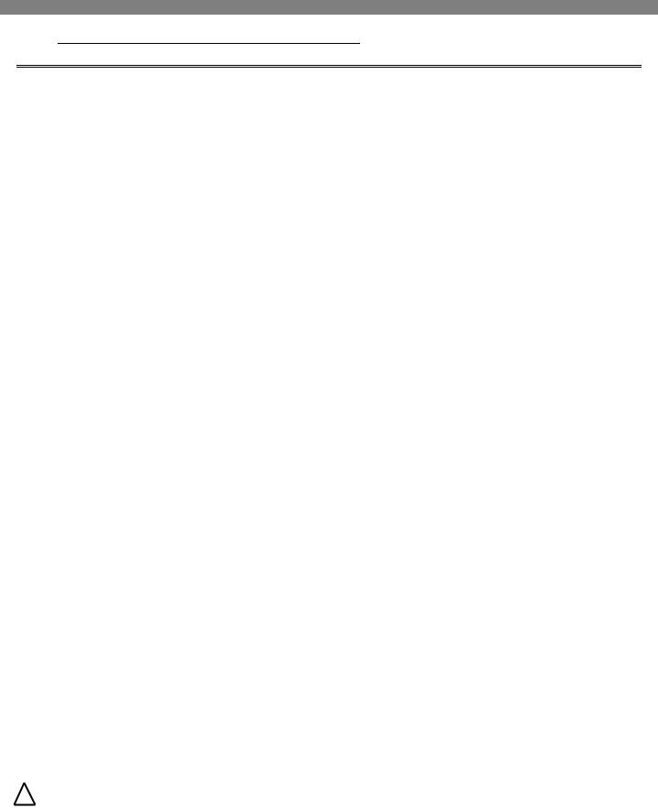
5. Features
5-1. Exterior
Front Control
Panel
LED, Touch
Water and Ice
Dispenser
1 Levers
Freezer Handle
Sticker written “F” inside handle for correct assembly
 Refrigerator Handle
Sticker written “R” inside handles for correct assembly
Included Parts
Hex Wrench(2.5mm) in User Manual Bag, Standoff
Screws on doors
! |
WARNING |
To avoid risk of electrical shock that can cause death or severe personal injury, |
10 / 79 |
disconnect unit from power before servicing unless tests require power. |
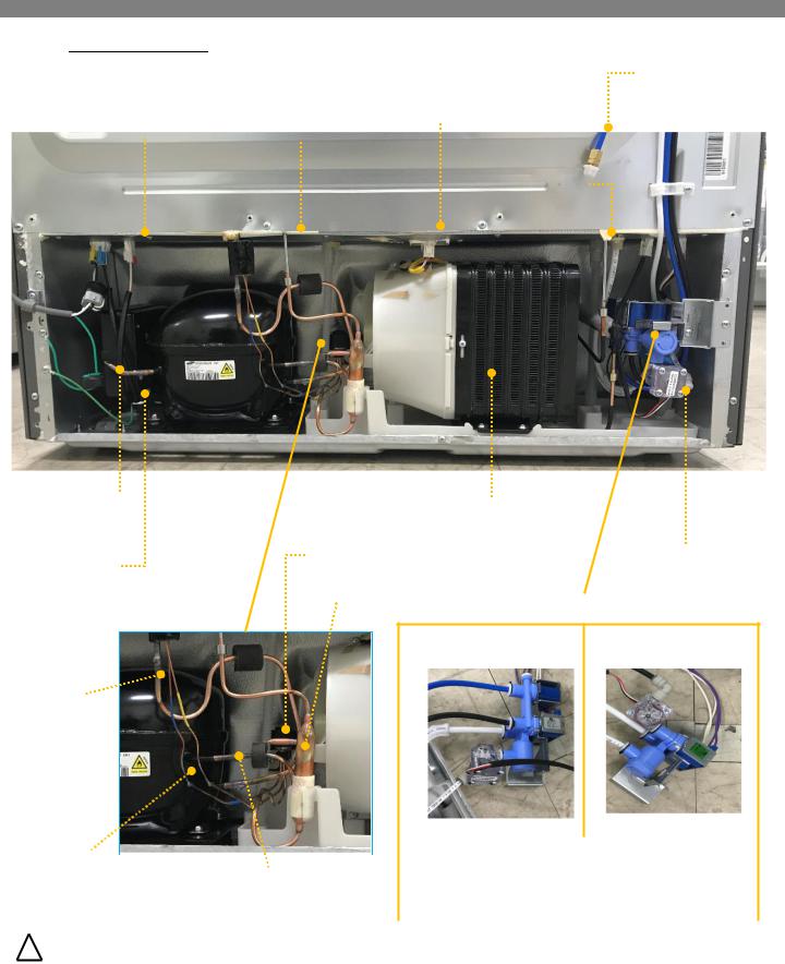
5. Features
5-2. Interior
Air Filter Cover
Icemaker Compartment
Icemaker and Ice Bin
Dispenser
Bin
Fixed
Shelves
Adjustable, Spill proof
Small Bin
Fixed
Bottom Bin
Mullion Bar
- Temperature Controlled
Pantry Drawer(RFP71KE*)
3 Steps Select Produce / Deli / Meat
- Wide Pantry
Drawer(RFP71KD*)
Filter Cover |
Water Filter |
Foldable Shelf
fixed by magnet after folding
Slid Away Split
Shelf
 Dairy Bin
 Utility Bin
Adjustable
 Gallon Bin
Adjustable
 Bottom Bin
Adjustable
Auto Pull Out Drawer
Humidity Controlled
Crisper
Vegetable & Fruit
Button Door Switch
Freezer Base Drawer
! |
WARNING |
To avoid risk of electrical shock that can cause death or severe personal injury, |
11 / 79 |
disconnect unit from power before servicing unless tests require power. |
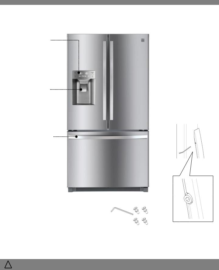
5. Features
5-3. Machine Room
Inverter Controller
Signal Connector
Process Part
in Compressor
Inverter
Controller
|
Condenser Fan |
Water Filter Inlet |
|
Connector(front) |
1/4 “ Tube) |
Hot Pipe |
Step Valve |
|
Connector(back) |
|
|
(Outlet) |
|
|
|
|
|
|
|
Hot Pipe |
|
|
(Inlet) |
|
Condenser |
Step Valve |
Flow Sensor |
|
in Valve Water |
Dryer |
Valve Water |
|
MODEL : RFP71KE** |
MODEL : RFP71KD** |
|
|
Pipe Suction |
|
|
|
|
|
|
|
|
Conn |
|
|
|
|
|
|
|
|
|
|
|
|
|
|
|
|
|
|
|
|
|
|
|
|
|
|
|
|
|
|
|
|
|
|
|
|
|
|
|
|
|
|
|
|
|
|
|
|
|
|
|
|
|
|
|
|
|
|
|
|
|
|
|
|
|
|
|
|
Black(1/4”) – Ice Maker Tube(R room) |
|
|
Capillary Tube |
|
|
|
|
|
|
||
|
|
|
|
White(1/4”) – Water Filter Outlet |
|
|
||
- Blue : F Eva. |
|
Pipe Condenser Conn |
|
|
|
|
||
|
|
|
White(5/16”) – Water Tank Inlet |
|
|
|||
- Yellow : Ice Maker Eva. |
(Discharge Part) |
|
|
|
|
|||
|
|
Blue(1/4”) - Ice Maker tube(F room) |
|
|
||||
|
|
|
|
|
|
|
|
|
|
|
|
|
|
|
|||
|
|
|
|
|
|
|
|
|
! WARNING |
To avoid risk of electrical shock that can cause death or severe personal injury, |
12 / 79 |
||||||
disconnect unit from power before servicing unless tests require power. |
||||||||
|
|
|
|
|
|
|
|
|
5. Features
5-4. Others
RT Sensor
Icemaker
Room Sensor
Ice Type (Cubed/Crushed) Selector
Water Tank
Assembly
Freezer
Fan Motor
Refrigerator
Fan Motor
Refrigerator Sensor
 Refrigerator Door Switches
Pantry
Drawer Sensor
Freezer Sensor
 Freezer Door Switch
! |
WARNING |
To avoid risk of electrical shock that can cause death or severe personal injury, |
13 / 79 |
disconnect unit from power before servicing unless tests require power. |
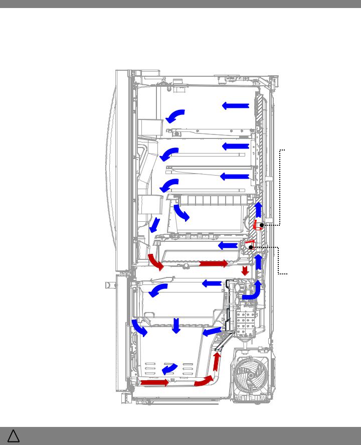
6. Flow Diagram
6-1. Cold Air Flow
Refrigerator |
|
Compartment |
|
|
Damper |
|
Control Air of |
|
Refrigerator |
|
Damper |
|
Control Air of Pantry |
|
Drawer |
Freezer |
(RFP71KE*) |
|
|
Compartment |
|
! |
WARNING |
To avoid risk of electrical shock that can cause death or severe personal injury, |
14 / 79 |
disconnect unit from power before servicing unless tests require power. |
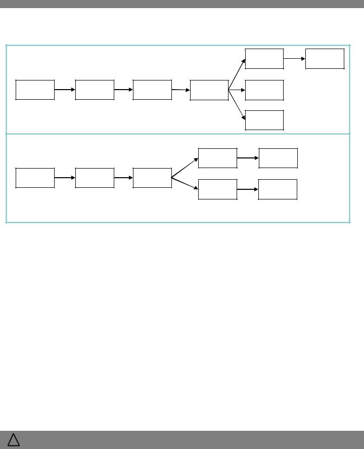
6. Flow Diagram
6-2. Water Flow |
|
|
|
|
|
RFP71KE* |
|
|
|
Water |
Water |
|
|
|
|
||
|
|
|
|
Tank |
Dispenser |
Main |
Water |
Flow |
Water |
Icemaker |
|
Water |
Filter |
Sensor |
Valve |
(R Room) |
|
|
|
|
|
Icemaker |
|
|
|
|
|
(F Room) |
|
RFP71KD* |
|
|
|
|
|
|
|
|
Water |
Water |
|
|
|
|
Tank |
Dispenser |
|
Main |
Water |
Water |
|
|
|
Water |
Filter |
Valve |
Flow |
Icemaker |
|
|
|
|
|
||
|
|
|
Sensor |
(R Room) |
|
□ Water Supply Pressure must be :
Min 30psi (207kPa, 2.1kgf/ ) Max 125psi (862Kpa, 8.8kgf/ )
If the water pressure exceeds 125psi,
a pressure reducing valve must be installed.If the water pressure is under 30psi,
a booster pump must be installed.
! |
WARNING |
To avoid risk of electrical shock that can cause death or severe personal injury, |
15 / 79 |
disconnect unit from power before servicing unless tests require power. |
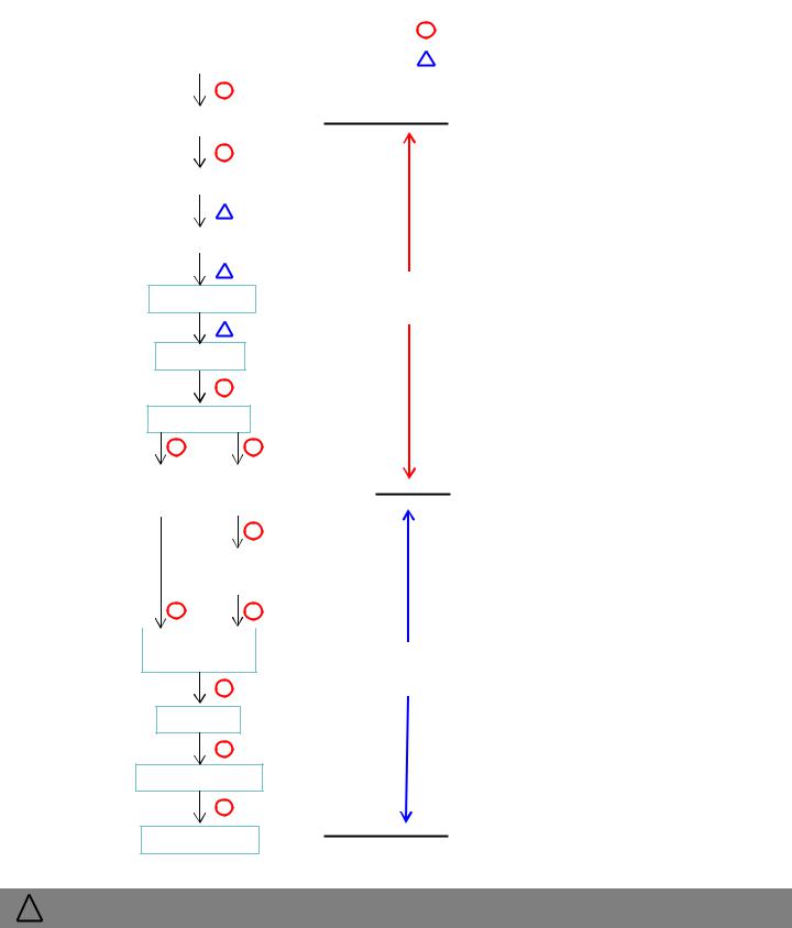
6. Flow Diagram
|
|
|
|
|
|
|
|
|
|
|
|
6-3. Refrigerant Flow and Welding Point |
|
|
|
|
|
||||||
SYMBOL |
|
METHOD |
POINTS |
|
|||||||
|
|
|
|
|
|
|
|
|
|||
|
|
|
|
|
|
|
|
|
|
|
|
|
|
|
|
|
|
|
|
Copper Welding (Ag 3%) |
11 |
|
|
|
|
|
|
|
|
|
|
||||
|
|
|
|
|
|
|
|
|
Lokring |
3 |
|
|
PIPE SVC(Discharge) |
|
|
|
|
||||||
|
|
|
|
|
|
|
|
|
|
|
|
|
|
|
|
|
|
|
|
|
|
|
|
|
|
COMPRESSOR |
|
|
|
|
|
|
|
||
|
|
|
|
|
|
|
|
You can force open all the step valve for 2 |
|||
|
|
|
|
|
|
|
|
||||
|
|
|
|
|
|
|
|
evaporators by following the next steps: |
|||
|
|
|
PIPE DEL |
|
|
|
|||||
|
|
|
|
|
|
|
|
|
|
||
|
|
|
|
|
|
|
1. |
Lock inner PCB |
|
|
|
|
|
|
|
|
|
|
|
|
|||
|
|
|
|
|
|
|
|
2. While pressing the “Refrigerator Temp” |
|||
|
|
|
PIPE HOT |
|
|
|
|
|
and “Freezer Temp” buttons, then |
||
|
|
|
|
|
|
|
|
|
press “Light” button 5 times |
|
|
|
|
|
|
|
|
|
|
|
|
|
|
CONDENSER
High Temperature
High Pressure
Refrigerant flow system :
DRYER AS
STEP VALVE
When the refrigerator valve is open, the refrigerant flows through the icemaker and freezer compartment.
CAPILLARY TUBE |
|
|
CAPILLARY TUBE |
|
||||
(BLUE) |
|
|
|
(YELLOW) |
|
|||
|
|
|
|
|
|
|
|
|
|
|
|
|
|
|
|
|
|
|
|
|
|
|
EVAPORATOR |
|
|
|
|
|
|
|
|
(Ice maker) |
|
||
|
|
|
|
|
||||
|
|
|
||||||
|
EVAPORATOR |
|||||||
|
(F Room) |
|
|
Low Temperature |
||||
Low Pressure
When the icemaker valve is open, the refrigerant flows through the freezer and icemaker compartment.
When the freezer valve is open, the refrigerant flows through the freezer compartment only.
There is no way to force open each individual valve.
PIPE SUC
PIPE SUC CONN
COMPRESSOR
! |
WARNING |
To avoid risk of electrical shock that can cause death or severe personal injury, |
16 / 79 |
disconnect unit from power before servicing unless tests require power. |
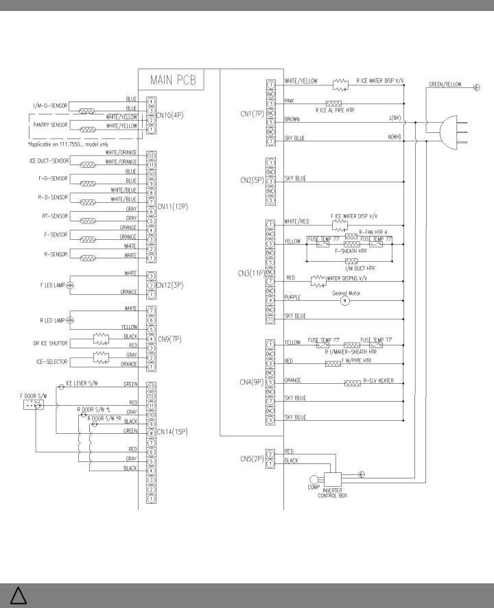
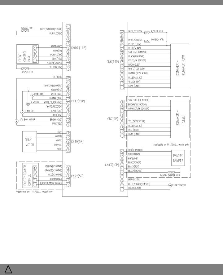
7. Wiring Diagram
7-1. Total View(1/2)
! |
WARNING |
To avoid risk of electrical shock that can cause death or severe personal injury, |
17 / 79 |
disconnect unit from power before servicing unless tests require power. |
7. Wiring Diagram
7-1. Total View(2/2)
! |
WARNING |
To avoid risk of electrical shock that can cause death or severe personal injury, |
18 / 79 |
disconnect unit from power before servicing unless tests require power. |

7. Wiring Diagram
7-2. Part View – Sensors
CN11
CN10
7-3. Part View – Eva Heater (SHEATH HTR)
CN4
CN3
! |
WARNING |
To avoid risk of electrical shock that can cause death or severe personal injury, |
19 / 79 |
disconnect unit from power before servicing unless tests require power. |
7. Wiring Diagram
7-4. Dispenser, DV(Mullion Bar), I/CASE Heater Operation
7-4-1. The dispenser heater is always on.
7-4-2. The DV heater is always on and located Between refrigerator doors.
7-4-3. The I/CASE heater cycles which is located inside the icemaker helps to remove residual ice from the ice case.
The heater turns on when the temperature reaches 21.2°F(-6°C) on and turns off when the temperature reaches 28.4°F(-2°C)
7-5. Other voltage
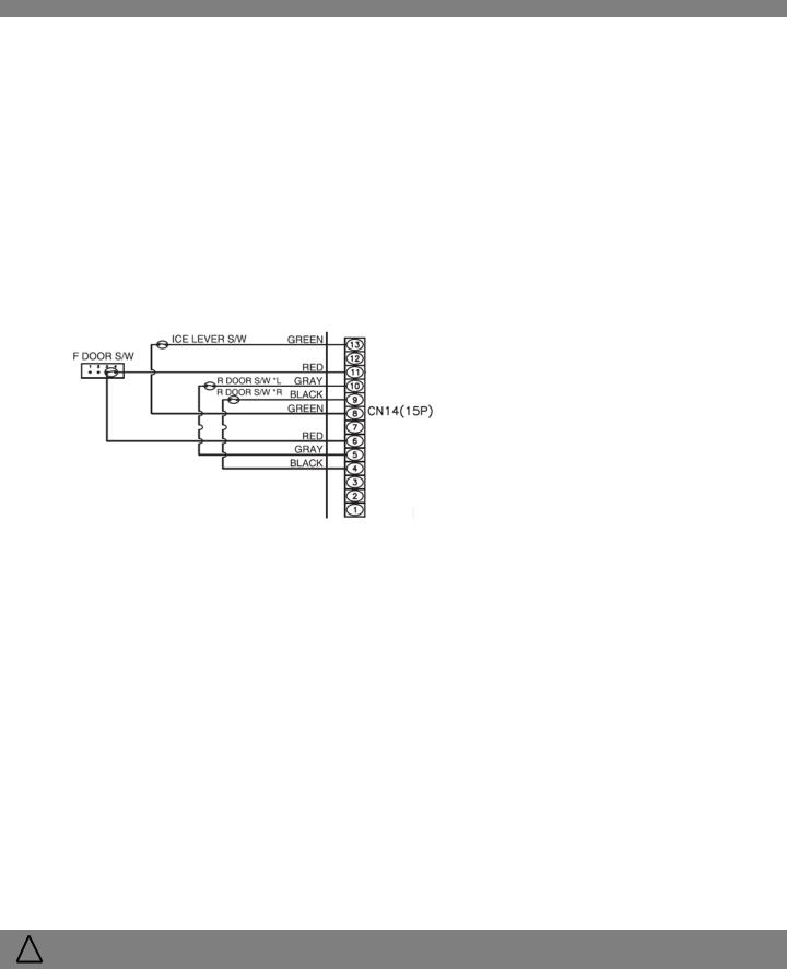
7-5-1. CN 14 (Switch)
Item |
|
Pin No. |
Open(On) |
Close(Off) |
|
|
|
|
|
|
|
R DOOR S/W L |
5 |
& 10 |
0V |
5V |
|
|
|
|
|
|
|
ICE LEVER S/W |
8 |
& 13 |
0V |
5V |
|
|
|
|
|
|
|
F DOOR S/W |
6 |
& 11 |
5V |
0V |
|
|
|
|
|
|
|
R DOOR S/W R |
4 |
& 9 |
0V |
5V |
|
|
|
|
|
|
|
7-5-2. CN 5 (Compressor Inverter)
Item |
Pin No |
|
On |
|
Off |
Remarks |
||
V |
|
Hz |
V |
|
Hz |
|||
|
|
|
|
|
||||
|
|
|
|
|
|
|
|
Frequency (Compressor Power |
Comp RPM |
1 & 2 |
3.3 |
|
50~125 |
6.5 |
|
- |
Consumption) Feedback to |
|
|
|
|
|
|
|
|
the main PCB |
|
|
|
|
|
|
|
|
|
! |
WARNING |
To avoid risk of electrical shock that can cause death or severe personal injury, |
20 / 79 |
disconnect unit from power before servicing unless tests require power. |
7. Wiring Diagram
7-5. Other voltage (continued)
7-5-3. CN 6 (Icemaker in the ice room)
|
Item |
|
Pin No |
|
On |
|
|
Off |
Remarks |
|
||
|
|
V |
|
Hz |
|
V |
|
Hz |
|
|||
|
|
|
|
|
|
|
|
|
||||
|
Water Tube Heater |
1 |
& 14 |
0 |
|
|
|
12 |
|
|
|
|
|
I/M Box Heater |
N/A |
N/A |
|
N/A |
|
N/A |
|
N/A |
|
|
|
|
I/M Stepping Motor |
1 |
& 9, 10 |
2.5 |
|
|
|
5 |
|
|
Bi-Directional |
|
|
Icemaker Power |
1 |
& 8 |
5 |
|
|
|
0 |
|
|
|
|
|
Icemaker LED |
1 |
& 6 |
0 |
|
|
|
10 |
|
|
|
|
|
Icemaker Temp. Sensor |
1 |
& 7 |
|
|
|
|
|
|
|
Sensor Table |
|
|
Icemaker Test Switch |
1 |
& 5 |
0 |
|
|
|
5 |
|
|
|
|
|
Start Position Check Sensor |
1 |
& 4 |
0(Start) |
|
|
|
5 |
|
|
|
|
|
Ice Bucket Full Check Sensor |
1 |
& 4 |
5(Full) |
|
|
|
0 |
|
|
|
|
|
7-5-4. CN 7 (Icemaker in the freezer compartment) 111.7550… model only |
|
|
|||||||||
|
|
|
|
|
|
|
|
|
|
|||
|
Item |
|
Pin No |
|
On |
|
|
Off |
Remarks |
|
||
|
|
V |
|
Hz |
|
V |
|
Hz |
|
|||
|
|
|
|
|
|
|
|
|
||||
|
I/M Stepping Motor |
1 |
& 8, 9 |
2.5 |
|
|
|
5 |
|
|
|
|
|
Icemaker Temp. Sensor |
1 |
& 7 |
|
|
|
|
|
|
|
Sensor Table |
|
|
Icemaker Test Switch |
1 |
& 4 |
0 |
|
|
|
5 |
|
|
|
|
|
Start Position Check Sensor |
1 |
& 3 |
0(Start) |
|
|
|
5 |
|
|
|
|
|
Ice Bucket Full Check Sensor |
1 & 5 |
5(Full) |
|
|
|
0 |
|
|
|
|
|
|
|
|
|
|
|
|
|
|
|
|
|
|
|
To avoid risk of electrical shock that can cause death or severe personal injury, |
|
|
21 / 79 |
||||||||
! WARNING disconnect unit from power before servicing unless tests require power. |
|
|
|
|||||||||
7. Wiring Diagram |
|
|
|
|
|
|
|
7-5. Other voltage (continued) |
|
|
|
|
|
|
|
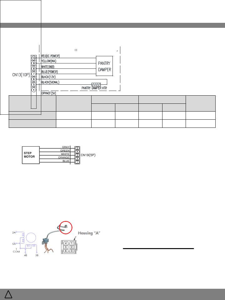
7-5-5. CN 13 (Damper) |
|
|
|
|
|
|
|
Item |
Pin No |
|
On |
|
Off |
|
Remarks |
V |
Hz |
V |
|
Hz |
|||
|
|
|
|
||||
Damper Heater |
5 & 6 |
0 |
- |
12 |
|
- |
|
Damper Signal |
1 & 7, 8, 9, 10 |
6 |
- |
0 |
|
- |
|
7-5-6. CN 19 (Step Valve) |
|
|
|
|
|
|
|
Item |
Pin No |
On |
|
|
Off |
|
Remarks |
||
V |
|
Hz |
V |
|
|
Hz |
|||
|
|
|
|
|
|
||||
Step Motor |
5 & 1, 2, 3, 4 |
0~12 swing |
|
- |
12 |
|
|
- |
|
|
|
|
|
|
|
|
|
|
|
Floating – pins 1, 2, 3, 4 are completed to circuit ground in sequence to operate the step valve
Following is the correct pin for PCB and step motor pin: Step Motor PCB Pin 1 = Step Motor Pin 5
PCB Pin 2 = Step Motor Pin 4
PCB Pin 3 = Step Motor Pin 1
PCB Pin 4 = Step Motor Pin 2
PCB Pin 5 = Step Motor Pin 3
|
|
|
|
|
|
|
Coil POINT |
[Ω] |
||
|
|
|
|
|
|
|
|
1 |
& 2, 3, 4, 5 |
40±4Ω |
|
|
|
|
|
|
|
Housing “A” |
2 |
&, 3, 4, 5 |
80±8Ω |
HOUSING "A" |
|
|
|
|
|
|
||||
|
|
|
|
|
|
|
|
|
||
|
|
|
|
|
|
|
Pin No. |
3 |
& 4, 5 |
80±8Ω |
Pin No. |
1 |
2 |
3 |
4 |
5 |
|
||||
|
|
|
|
|||||||
|
|
|
|
|
|
|
|
4 |
& 5 |
80±8Ω |
Color of lead wire |
GRAY |
BLACK |
ORANGE |
BLUE |
YELLOW |
|
|
|||
|
|
|
|
|
||||||
! |
WARNING |
To avoid risk of electrical shock that can cause death or severe personal injury, |
22 / 79 |
disconnect unit from power before servicing unless tests require power. |
 Loading...