


11070102311
Kenmore 11070102311, 11070102312, 11072102310, 11072332510, 11072342510 Installation Guide
...
Dryer Installation instructions
Instrucciones de instalaci6n de la secadora
instructions d'lnstallation de la s_cheuse
English / Espa_ol / Fran_:ais
Table of Contents / [ndice / Table des Mafieres ......4
Ke
29" Wide Gas (U.S.A. and Canada) & Electric (Canada Only) Dryer
ModeJos de 29 °`a gas (EEoUUoy Canada) y EJ_ctrica (SoJo en Canada)
Mod@Jes de 29" de largeur @gas (EooUoet Canada) et EJectrique (Canada uniquement)
P/N W10562366A
Sears Brands Management Corporation
Hof_man Estates, IL 60179 U.S.A.
www.kenmore.com
www.sears.com
Sears Canada inc.
Toronto, Ontario, Canada M5B 2C3
www.sears.ca
iNSTALLATiON NOTES
Date of purchase:
Date of installation:
Installer:
Model number:
Serial number:
NOTAS SOBRE LA INSTALACION
Fecha de compra:
Fecha de instalaci6n:
Instalador:
N6mero de modelo:
N6mero de serie:
NOTES CONCERNANT
L'INSTALLATION
Date d'achat :
Date d'installation :
Installateur :
Num6ro de module :
Num6ro de s6rie :
DRYER SAFETY
Your safety and the safety of others are very important.
We have provided many important safety messages in this manual and on your appliance. Always read and obey all safety
messages.
This is the safety alert symbol.
This symbol alerts you to potential hazards that can kill or hurt you and others.
All safety messages will follow the safety alert symbol and either the word "DANGER" or "WARNING."
These words mean:
You can be killed or seriously injured if you don't immediately
follow instructions.
You can be killed or seriously injured if you don't follow
instructions.
All safety messages will tell you what the potential hazard is, tell you how to reduce the chance of injury, and tell you what can
happen if the instructions are not followed.
WARNING - ...i.kof
- Clothes dryer installation must be performed by a qualified installer.
- Install the clothes dryer according to the manufacturer's instructions and local codes.
- Do not install a clothes dryer with flexible plastic venting materials or flexible metal
(foil type) duct. if flexible metal duct is installed, it must be of a specific type identified
by the appliance manufacturer as suitable for use with clothes dryers. Flexible venting
materials are known to collapse, be easily crushed, and trap lint. These conditions will
obstruct clothes dryer airflow and increase the risk of fire.
- To reduce the risk of severe injury or death, follow all installation instructions.
- Save these instructions.
2
iMPORTANT."The gas installation must conform with local codes, or in the absence of local codes, with the National Fuel Gas
Code, ANSI Z223.1iNFPA 54 or the Canadian Natural Gas and Propane Installation Code, CSA B149.1.
The dryer must be electrically grounded in accordance with local codes, or in the absence of local codes, with the National
Electrical Code, ANSIiNFPA 70 or Canadian Electrical Code, CSA C22.1.
WARNING: For your safety, the information in this manual must be followed to minimize
the risk of fire or explosion, or to prevent property damage, personal injury, or death.
- Do not store or use gasoline or other flammable vapors and liquids in the vicinity of this
or any other appliance.
- WHAT TO DO iF YOU SMELL GAS:
• Do not try to light any appliance.
= Do not touch any electrical switch; do not use any phone in your building.
• Clear the room, building, or area of all occupants.
e Immediately call your gas supplier from a neighbor's phone. Follow the gas supplier's
instructions.
= if you cannot reach your gas supplier, call the fire department.
- Installation and service must be performed by a qualified installer, service agency, or
the gas supplier.
WARNING: Gas leaks cannot always be detected by smell.
Gas suppliers recommend that you use a gas detector approved by UL or CSA.
For more information, contact your gas supplier.
If a gas leak is detected, follow the "What to do if you smell gas" instructions.
IMPORTANT SAFETY INSTRUCTIONS
WARNING: To reduce the risk of fire, electric shock, or injury to persons when using the dryer, follow basic precautions,
including the following:
[] Read all instructions before using the dryer.
[] Do not place items exposed to cooking oils in your dryer.
Items contaminated with cooking oils may contribute to
a chemical reaction that could cause a load to catch fire.
[] Do not dry articles that have been previously cleaned in,
washed in, soaked in, or spotted with gasoline, dry-
cleaning solvents, or other flammable or explosive
substances as they give off vapors that could ignite or
explode.
[] Do not allow children to play on or in the dryer. Close
supervision of children is necessary when the dryer is
used near children.
[] Before the dryer is removed from service or discarded,
remove the door to the drying compartment.
[] Do not reach into the dryer if the drum is moving.
[] Do not install or store the dryer where it will be exposed
to the weather.
[] Do not tamper with controls.
[] Do not repair or replace any part of the dryer or attempt
any servicing unless specifically recommended in this
Use and Care Guide or in published user=repair
instructions that you understand and have the skills to
carry out.
[] Do not use fabric softeners or products to eliminate static
unless recommended by the manufacturer of the fabric
softener or product.
[] Do not use heat to dry articles containing foam rubber or
similarly textured rubber-like materials.
[] Clean lint screen before or after each load.
[] Keep area around the exhaust opening and adjacent
surrounding areas free from the accumulation of lint, dust,
and dirt.
[] The interior of the dryer and exhaust vent should be
cleaned periodically by qualified service personnel.
[] See "Electrical Requirements" located in the installation
instructions for grounding instructions.
SAVE THESE INSTRUCTIONS
in the State of Massachusetts, the following installation instructions apply:
[] installations and repairs must be performed by a qualified or licensed contractor, plumber, or gasfitter qualified or licensed by
the State of Massachusetts.
[] if using a ball valve, it shall be a T-handle type.
[] A flexible gas connector, when used, must not exceed 3 feet.
State of California Proposition 65 Warnings:
WARNING: This product contains one or more chemicals known to the State of California to cause cancer.
WARNING: This product contains one or more chemicals known to the State of California to cause birth defects or other
reproductive harm.
IMPORTANT SAFETY INSTRUCTIONS
When discarding or storing your old clothes dryer, remove the door.
SAVE THESE INSTRUCTIONS
Table of Con_en_s
DRYER SAFETY ...................................................................................... 2
INSTALLATION REQUIREMENTS ........................................................... 5
Tools and Parts .............................................................................. 5
Location Requirements ................................................................... 6
ELECTRIC DRYER POWER HOOKUP-CANADA ONLY ........................... 7
Electrical Requirements ................................................................. 7
GAS DRYER POWER HOOKUP ............................................................. 7
Electrical Requirements ................................................................. 7
Gas Supply Requirements .............................................................. 8
VENTING .............................................................................................. 9
Venting Requirements ................................................................... 9
Plan Vent System ......................................................................... 10
Venting Kits.................................................................................. 11
Instcill Vent System ....................................................................... 12
INSTALL LEVELING LEGS..................................................................... 12
MAKE GAS CONNECTION .................................................................. 12
CONNECT VENT ................................................................................. 13
LEVEL DRYER ...................................................................................... 13
COMPLETE INSTALLATION CHECKLIST ............................................... 14
REVERSE DOOR SWING (OPTIONAL) ................................................. 14
TROUBLESHOOTING ........................................................................... 16
indite
SEGURIDAD DE LA SECADORA .......................................................... 17
REQUISITOS DE INSTALAa6N .......................................................... 19
Herramlentas y plezas ................................................................ 19
Requlsltos de ub_caci6n ............................................................... 20
CONEXION DEL SUMINISTRO DE LA SECADORA
ELECTRICA=SOLO EN CANAD,_ ......................................................... 22
Requisffos el6ctricos .................................................................... 22
CONEXI6N DEL SUMINISTRO
DE LA SECADORA A GAS ................................................................. 22
Requisffos el_ctr_cos .................................................................... 22
Requisitos del suministro de gas .................................................. 23
VENTILACI6N .................................................................................... 25
Requisffos de ventilac_6n ............................................................. 25
Planiflcaci6n del sistema de ventilc=ci6n ...................................... 26
Juegos de ventilac_6n ................................................................. 27
Instalaci6n del slstema de ventilaci6n ......................................... 28
INSTALACI6N DE LAS PATAS NIVELADORAS .................................... 28
CONEXION DEL SUMINISTRO DE GAS .............................................. 29
CONEXION DEL DUCTO DE ESCAPE .................................................. 29
NIVELACION DE LA SECADORA ........................................................ 30
LISTA DE CONTROL DE LA INSTALACION TERMINADA .................... :30
CAMBIO DEL SENTIDO DE ABERTURA DE LA PUERTA ....................... 31
SOLUCI6N DE PROBLEMAS .............................................................. 33
Table des
SF:CURITF: DE LA SECHEUSE ............................................................... 34
EXIGENCES D'INSTALLATION ............................................................. 36
Outillage et pi@ces ....................................................................... 36
Exlgences d'emplacement ............................................................ 37
RACCORDEMENT )k L'ALIMENTATION ELECTRIQUE
DE LA Sf:CHEUSE ELECTRIQUE - CANADA SEULEMENT ...................... 39
Sp6ciflcations 61ectriques ............................................................. 39
RACCORDEMENT }k L'ALIMENTATION
D'UNE S_:CHEUSE ,_GAZ .................................................................... 39
Sp6ciflcations 61ectriques ............................................................. 39
Sp6citlcations de rcslimentation en gaz ....................................... 40
ma_i_res
L'EVACUATION ................................................................................... 42
Exlgences ¢oncernant r_vacuatlon .............................................. 42
Planiflcafion du syst_me d'6vacuation ......................................... 43
Trousses d'6vacuation ................................................................. 44
Installation du ckcuit d'6vacuation ............................................... 45
INSTALLATION DES PIEDS DE NIVELLMENT ....................................... 45
RACCORDEMENT AU GAZ .................................................................. 46
RACCORDEMENT DU CONDUIT D'_:VACUATION ............................... 47
R_:GLAGE DE L'APLOMB DE LA SECHEUSE ......................................... 47
ACHEVER L'INSTALLATION = LISTE DE V_:RIFICATION ...................... 48
iNVERSiON DU SENS DE L'OUVERTURE DE LA PORTE (FACULITAF).. 48
DEPAN NAGE ....................................................................................... 31
4

iNSTALLATiON REQUIREMENTS
Tools and Parts
Gather the required tools and parts before starting installation.
Tools needed for oil installations:
Tools needed for gas installations:
Flat-blade screwdriver
#2 Phillips screwdriver
8" or 10" pipe wrench 8" or 10" adjustable wrench
(for gas connections)
1/4" nut driver or socket
wrench (recommended)
Tin snips (new vent
installations)
Tape measure Vent clamps
Level Pliers
Adjustable wrench that
opens to 1" (25 mm) or
hex-head socket wrench
Caulking gun and compound (for
installing new exhaust vent)
Pipe-joint compound
resistant to LP gas
Ports supplied:
Leveling legs (4)
Parts package is located in dryer drum. Check that all parts
are included.
Ports needed:
Check local codes. Check existing electrical supply and venting.
See "Electrical Requirements" and "Venting Requirements" before
purchasing parts.
Mobile home installations require metal exhaust system hardware. For
more information_ see "Assistance or Service" section in your "Use and
Care Guide",
Optional Equipment: (Not supplied with dryer)
Refer to your "Use and Care Guide" for information about accessories
available for your dryer.
Utility knife
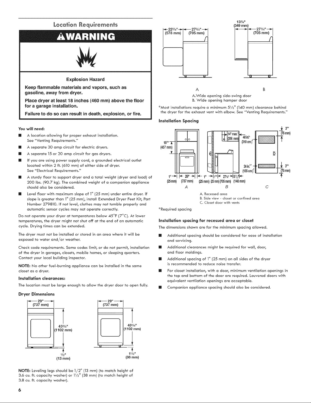
Explosion Hazard
Keep flammable materials and vapors, such as
gasoline, away from dryer.
Place dryer at least 18 inches (460 ram) above the floor
for a garage installation.
Failure to do so can result in death, explosion, or fire.
You will need:
[] A location allowing for proper exhaust installation.
See "Venting Requirements."
[] A separate 30 amp circuit for electric dryers.
[] A separate 15 or 20 amp circuit for gas dryers.
[] if you are using power supply cord, a grounded electrical outlet
located within 2 ft. (610 ram) of either side of dryer.
See "Electrical Requirements."
[] A sturdy floor to support dryer and a total weight (dryer and toad) of
200 Ibs. (90.7 kg). The combined weight of a companion appliance
should also be considered.
[] Level floor with maximum slope of 1" (25 mm) under entire dryer. If
slope is greater than 1" (25 ram), install Extended Dryer Feet Kit, Part
Number 279810. If not level, clothes may not tumble properly and
automatic sensor cycles may not operate correctly.
Do not operate your dryer at temperatures below 45°F (7°C). At lower
temperatures, the dryer might not shut off: at the end of an automatic
cycle. Drying times can be extended.
The dryer must not be installed or stored in an area where it will be
exposed to water and/or weather.
Check code requirements. Some codes limit, or do not permit, installation
of the dryer in garages, closets, mobile homes, or sleeping quarters.
Contact your local building inspector.
NOTE: No other fuel-burning appliance can be installed in the same
closet as a dryer.
installation clearances:
The location must be large enough to allow the dryer door to open fully.
Dr_,er Dimensions
_,_ 2g" -_
(737 turn)
43
110; ram)
t
I/2ml
(13 mm)
•_ 2g" _
(737 ram) I
--T
4,33/a''
(1102 ram)
1lh"
(38 ram)
273/4. ___
(705 ram)
[
133/4"
(34g ram)
_---- 27a/4,, _
(705 ram)
/-
A B
A.Wide opening side-swing door
B. Wide opening hamper door
_Most installations require a minimum 51/2 '' (140 ram) clearance behind
the dryer for the exhaust vent with elbow. See "Venting Requirements."
Installation Spacing
_,m¢' max; _--_in._
I_ 14_ m (310cm)2=
[_ 24in._*-
._ (155cm)2
1"'-_ _- 2g"-_l _- 1" -_h"*_ 2734"H5V2"_e-
(25ram) (737mm) (25mm)(25mm)(705mm)(140ram)
A B
A. Recessed area
B. Side view - closet or confined area
C. Closet door with vents
_f 3 I1_
_76mm)
(76mm)
_Required spacing
installation spacing for recessed area or closet
The dimensions shown are for the minimum spacing allowed.
[] Additional spacing should be considered for ease of installation
and servicing.
[] Additional clearances might be required for wall, door,
and floor moldings.
[] Additional spacing of 1" (25 ram) on all sides of the dryer
is recommended to reduce noise transfer.
[] For closet installation, with a door, minimum ventilation openings in
the top and bottom of the door are required. Louvered doors with
equivalent ventilation openings are acceptable.
[] Companion appliance spacing should also be considered.
NOTE: Leveling legs should be 1/2" (13 mm) (to match height of
3.6 cu. ft. capacity washer) or 11/2'' (38 mm) (to match height of
3.8 cu. ft. capacity washer).
6
Mobile home - Additional installation requirements
This dryer is suitable for mobile home installations. The installation must
conform to the Manufactured Home Construction and Safety Standard,
Title 24 CFR, Part 3280 (formerly the Federal Standard for Mobile Home
Construction
and Safety, Title 24, HUD Part 280) or the Canadian Manufactured Home
Standard CAN/CSA-Z240 MH.
[] Metal exhaust system hardware, available for purchase. For further
information, please reference the "Assistance or Service" section of
your "Use and Care Guide".
[] Special provisions must be made in mobile homes to introduce
outside air into the dryer. The opening (such as a nearby window)
should be at least twice as large as the dryer exhaust opening.
ELECTRIC DRYER POWER
HOOKUP - CANADA ONLY
E[e¢#ica[ Requirements
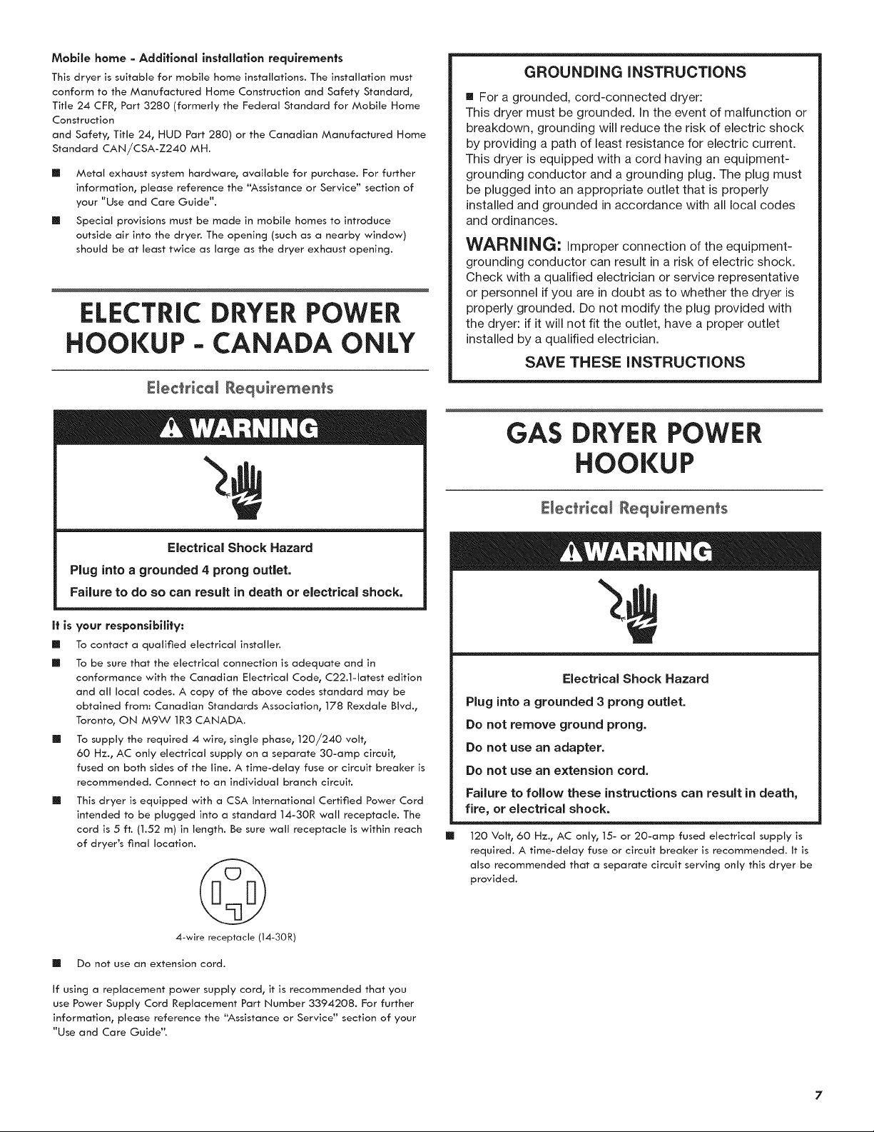
Electrical Shock Hazard
Plug into a grounded 4 prong ou0et.
Failure to do so can result in death or electrical shock,
it is your responsibility:
[] To contact a qualified electrical installer.
[] To be sure that the electrical connection is adequate and in
conformance with the Canadian Electrical Code, C22.1-1atest edition
and all local codes. A copy of the above codes standard may be
obtained from: Canadian Standards Association, 178 Rexdale Blvd.,
Toronto, ON M9W 1R3 CANADA.
[] To supply the required 4 wire, single phase, 120/240 volt,
60 Hz., AC only electrical supply on a separate 30-amp circuit,
fused on both sides of the line. A time-delay fuse or circuit breaker is
recommended. Connect to an individual branch circuit.
This dryer is equipped with a CSA International Certified Power Cord
intended to be plugged into a standard 14-30R wall receptacle. The
cord is 5 ft. (1.52 m) in length. Be sure wall receptacle is within reach
of dryer's final location.
4-wire receptacle (14-30R)
[] Do not use an extension cord.
If using a replacement power supply cord, it is recommended that you
use Power Supply Cord Replacement Part Number 3394208. For further
information, please reference the "Assistance or Service" section of your
"Use and Care Guide".
GROUNDING iNSTRUCTiONS
m For a grounded, cord-connected dryer:
This dryer must be grounded. In the event of malfunction or
breakdown, grounding will reduce the risk of electric shock
by providing a path of least resistance for electric current.
This dryer is equipped with a cord having an equipment-
grounding conductor and a grounding plug. The plug must
be plugged into an appropriate outlet that is properly
installed and grounded in accordance with all local codes
and ordinances.
WARNING: Improper connection of the equipment-
grounding conductor can result in a risk of electric shock.
Check with a qualified electrician or service representative
or personnel if you are in doubt as to whether the dryer is
properly grounded. Do not modify the plug provided with
the dryer: if it will not fit the outlet, have a proper outlet
installed by a qualified electrician.
SAVE THESE INSTRUCTIONS
GAS DRYERPOWER
HOOKUP
E[ec[rica[ Requirements
Electrical Shock Hazard
Plug into a grounded 3 prong outlet.
Do not remove ground prong.
Do not use an adapter.
Do not use an extension cord.
Failure to follow these instructions can result in death,
fire, or electrical shock.
[]
120 Volt, 60 Hz., AC only, 15- or 20-amp fused electrical supply is
required. A time-delay fuse or circuit breaker is recommended. It is
also recommended that a separate circuit serving only this dryer be
provided.
GROUNDING iNSTRUCTiONS
[] For a grounded, cord-connected dryer:
This dryer must be grounded. In the event of malfunction or
breakdown, grounding will reduce the risk of electric shock
by providing a path of least resistance for electric current.
This dryer is equipped with a cord having an equipment-
grounding conductor and a grounding plug. The plug must
be plugged into an appropriate outlet that is properly
installed and grounded in accordance with all local codes
and ordinances.
WARNING-" Improper connection of the equipment-
grounding conductor can result in a risk of electric shock.
Check with a qualified electrician or service representative
or personnel if you are in doubt as to whether the dryer is
properly grounded. Do not modify the plug provided with
the dryer: if it will not fit the outlet, have a proper outlet
installed by a qualified electrician.
SAVE THESE INSTRUCTIONS
Explosion Hazard
Use a new CSA International approved gas supply line.
instal[ a shut=off valve.
Securely tighten all gas connections.
If connected to LP, have a qualified person make sure
gas pressure does not exceed 13" (330 ram) water
column.
Examples of a qualified person include:
licensed heating personnel,
authorized gas company personnel, and
authorized service personnel.
Failure to do so can result in death, explosion, or fire.
Gas type
Natural gas:
This dryer is equipped for use with Natural Gas. It is design-certified by
CSA International for LP (propane or butane) gases with appropriate
conversion.
[]
Your dryer must have the correct burner for the type of gas
in your home. Burner information is located on the rating
plate in the door well of your dryer. If this information does
not agree with the type of gas available, please reference the
"Assistance or Service" section of the "Use and Care Guide".
LP gas conversion:
Conversion must be made by a qualified technician.
No attempt shall be made to convert the dryer from the gas specified
on the model/serial rating plate for use with a different gas without
consulting the serving gas supplier.
IMPORTANT: The gas installation must conform with local codes, or in the
absence of local codes, with the National Fuel Gas Code, ANSi Z223.1/
NFPA 54 or the Canadian Natural Gas and Propane Installation Code,
CSA B149.1.
Gas supply line
[]
[]
[]
[]
1/2" NPT pipe is recommended.
3/8" approved tubing is acceptable for lengths under 20 ft. (6.1 m) if
local codes and gas supplier permit.
Must include 1/8" NPT minimum plugged tapping accessible for test
gauge connection, immediately upstream of the gas connection to
the dryer (see illustration).
Must include a shutoff valve:
in the U.S.A.:
An individual manual shutoff valve must be installed within
six (6) feet (1.8 m) of the dryer in accordance with the National Fuel
Gas Code, ANSI Z223.1.
in Canada:
An individual manual shutoff valve must be installed in accordance
with the B149.1, Natural Gas and Propane Installation Code. It is
recommended that an individual manual shutoff valve be installed
within six (6) feet (1.8 m)
of the dryer.
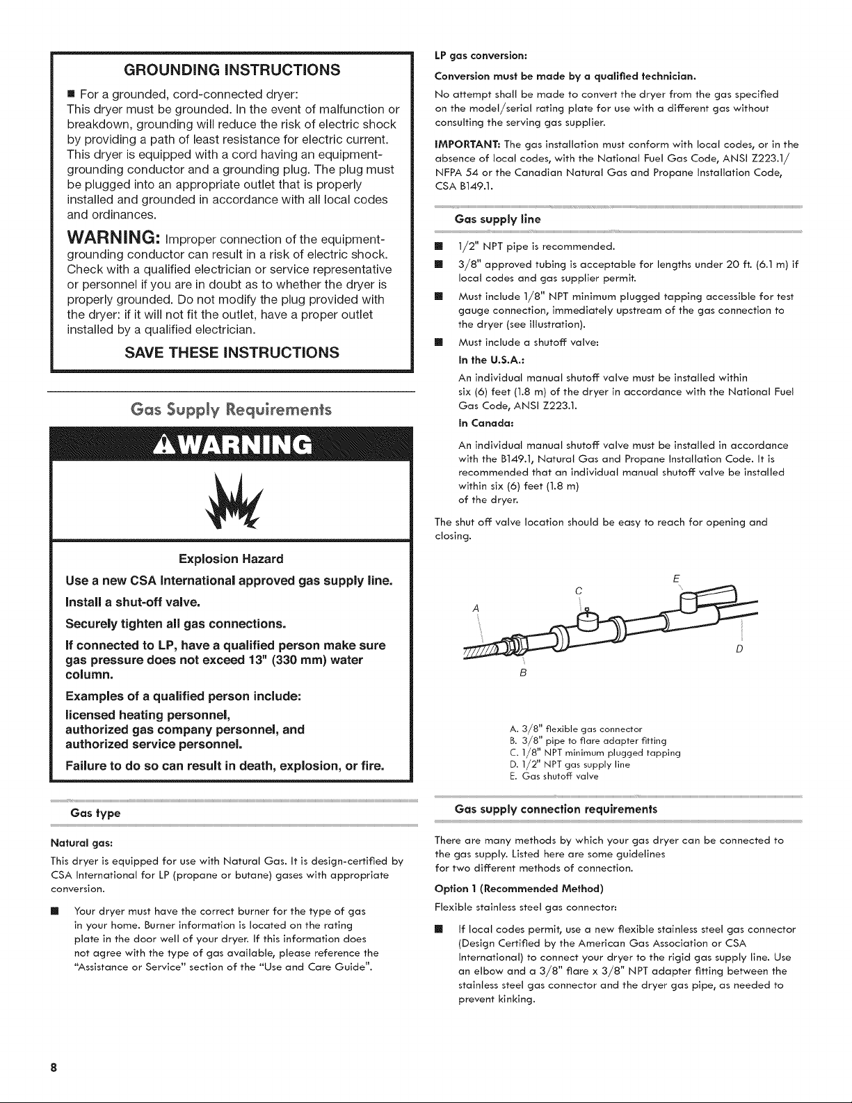
The shut off valve location should be easy to reach for opening and
closing.
E
B
A. 3/8" flexible gas connector
B. 3/8" pipe to flare adapter fitting
C. 1/8" NPT minimum plugged tapping
D. 1/2" NPT gas supply line
E. Gas shutoff valve
Gas supply connection requirements
There are many methods by which your gas dryer can be connected to
the gas supply. Listed here are some guidelines
for two different methods of connection.
Option I (Recommended Method)
Flexible stainless steel gas connector:
[]
If local codes permit, use a new flexible stainless steel gas connector
(Design Certified by the American Gas Association or CSA
International) to connect your dryer to the rigid gas supply line. Use
an elbow and a 3/8" flare x 3/8" NPT adapter fitting between the
stainless steel gas connector and the dryer gas pipe, as needed to
prevent kinking.
Option2(AlternateMethod)
Approvedaluminumorcoppertubing:
[] Lengthsunder20ft.(6.1m)canuse3/8"approvedtubing
(ifcodesandgassupplierpermit).
[] ifyouareusingNaturalGas,donotusecoppertubing.
[] 3/8"flarex3/8"NPTadapterfittingbetweendryerpipeand3/8"
approvedtubing.
[] Lengthsover20ft.(6.1m)shoulduselargertubingandadifferent
sizeadapterfitting.
[] ifyourdryerhasbeenconvertedtouseLPgas,3/8"LPcompatible
coppertubingcanbeused.Ifthetotallengthofthesupplylineis
morethan20ft.(6.1m),uselargerpipe.
NOTE:PipejointcompoundsthatresisttheactionofLPgasmustbe
used.DonotuseTEFLON®ttape.
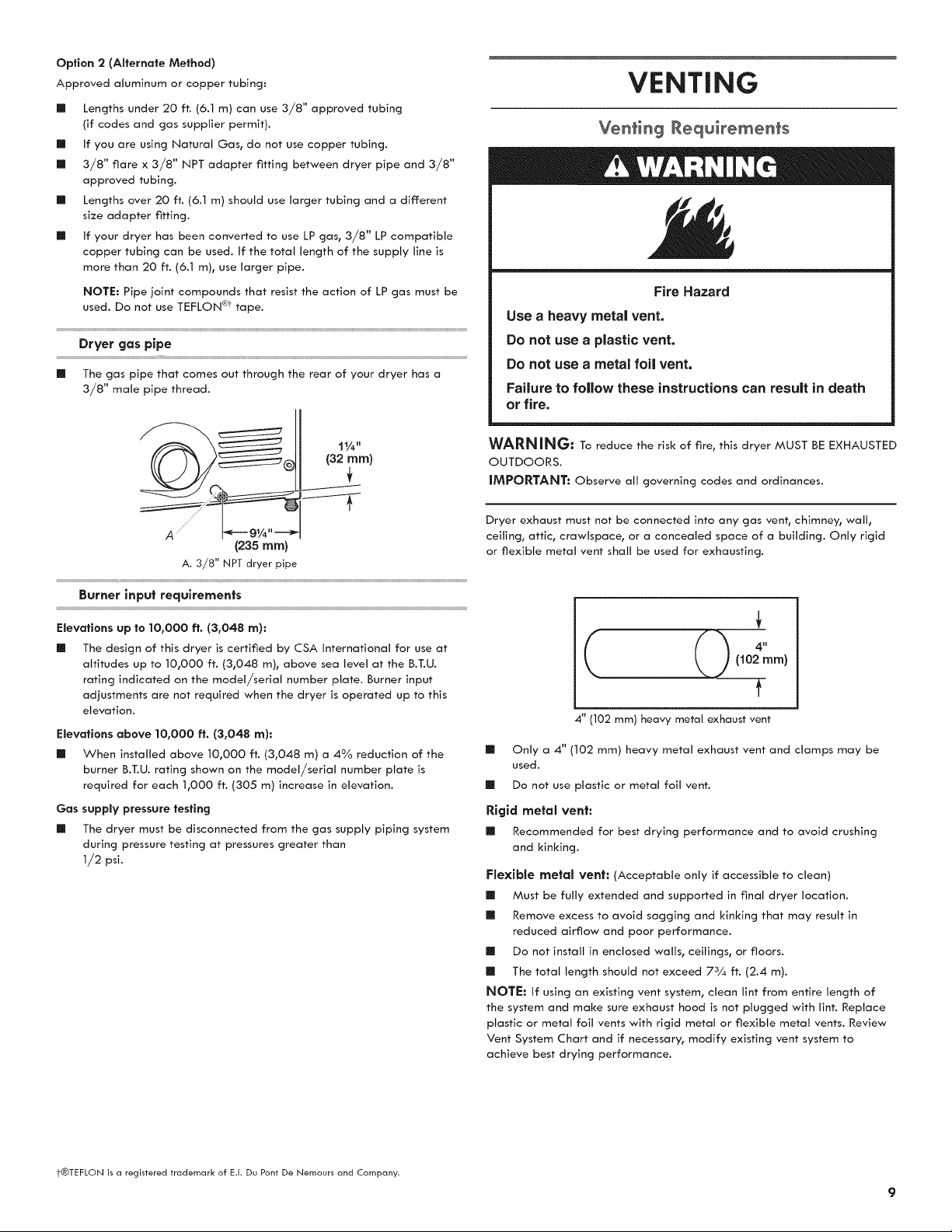
Dryer gas pipe
[] The gas pipe that comes out through the rear of your dryer has a
3/8" male pipe thread.
VENTING
Venting Requirements
Fire Hazard
Use a heavy rnetal vent.
Do not use a plastic vent.
Do not use a metal foil vent.
Failure to follow these instructions can result in death
or fire.
1¼"
(32 ram)
WARNING; Toreducetheriskoffire,thisdryerMUSTBEEXHAUSTED
OUTDOORS.
IMPORTANT: Observe all governing codes and ordinances.
//
A -=_-- 9¼"--_
(235 ram)
A. 3/8" NPT dryer pipe
Burner input requirements
Elevations up to lO,O00 ft. (3,048 an):
[] The design of this dryer is certified by CSA international for use at
altitudes up to 10,000 ft. (3,048 m), above sea level at the B.T.U.
rating indicated on the model/serial number plate. Burner input
adjustments are not required when the dryer is operated up to this
elevation.
Elevations above 10,000 ft. (3,048 an):
[] When installed above 10,000 ft. (3,048 m) a 4% reduction of the
burner B.T.U. rating shown on the model/serial number plate is
required for each 1,000 ft. (305 m) increase in elevation.
Gas supply pressure testing
[] The dryer must be disconnected from the gas supply piping system
during pressure testing at pressures greater than
1/2 psi.
Dryer exhaust must not be connected into any gas vent, chimney, wall,
ceiling_ attic, crawlspace, or a concealed space of a building. Only rigid
or flexible metal vent shall be used for exhausting.
((),
(102mm)
t
4" (102 ram) heavy metal exhaust vent
[] Only a 4" (102 mm) heavy metal exhaust vent and clamps may be
used.
[] Do not use plastic or metal foil vent.
Rig(c{ metal vent:
[] Recommended for best drying performance and to avoid crushing
and kinking.
F(ex(b(e mete( vent: (Acceptable only if accessible to clean)
[] Must be fully extended and supported in final dryer location.
[] Remove excess to avoid sagging and kinking that may result in
reduced airflow and poor performance.
[] Do not install in enclosed walls, ceilings, or floors.
[] The total length should not exceed 73¼ ft. (2.4 m).
NOTE: If using an existing vent system, clean tint from entire length of
the system and make sure exhaust hood is not plugged with lint. Replace
plastic or metal foil vents with rigid metal or flexible metal vents. Review
Vent System Chart and if necessary, modify existing vent system to
achieve best drying performance.
t®TEFLON is a registered trademark of E.I. Du Pont De Nemours and Company.
Exhaust hoods:
[] Must be at least 12" (305 ram) from ground or any object that may
obstruct exhaust (such as flowers_ rocks_ bushes_ or snow).
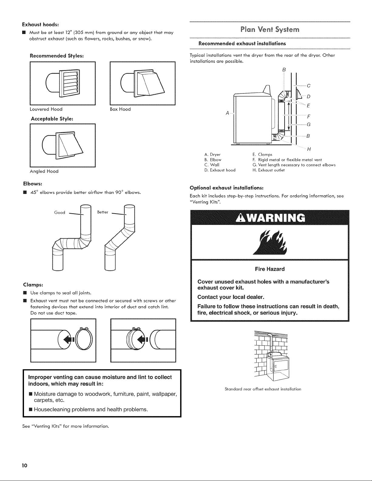
Recommended Styles:
Louvered Hood
Acceptable Style:
Box Hood
Angled Hood
Elbows:
[] 45 ° elbows provide better airflow than 90 ° elbows.
Clamps:
[]
[]
Use clamps to seat all joints.
Exhaust vent must not be connected or secured with screws or other
fastening devices that extend into interior of duct and catch lint.
Do not use duct tape.
improper venting can cause moisture and lint to collect
indoors, which may result in:
[] Moisture damage to woodwork, furniture, paint, wallpaper,
carpets, etc.
[] Housecleaning problems and health problems.
PJan Ven_ System
Recommended exhaust JnstaJJatJons
Typical installations vent the dryer from the rear of the dryer. Other
installations are possible.
B
H
A. Dryer E. Clamps
B. Elbow F. Rigid metal or flexible metal vent
C. Wall G, Vent length necessary to connect elbows
D. Exhaust hood H. Exhaust outlet
Optional exhaust installations:
Each kit includes step-by-step instructions. For ordering information_ see
"Venting Kits".
Fire Hazard
Cover unused exhaust holes with a manufacturer's
exhaust cover kit.
Contact your local dealer.
Failure to follow these instructions can result in death,
fire, electrical shock, or serious injury.
Standard rear offset exhaust installation
See "Venting Kits" for more information.
10

Alternate installations for dose clearances
Venting systems come in many varieties. Select the type best for your
installation. Two close-clearance installations are shown. Refer to the
manufacturer's instructions.
Over-The-Top installation (also available with one offset elbow)
Periscope installation
NOTE: The following kits for close clearance alternate installations are
available for purchase.
Ven_ing Ki_s
For more information, call ]=800=469=4663, or visit us
at www.seors.com, in Canada, call
1-800-469-4663 or visit us at www.seors.co.
Port Number Descrlpffons
8171587RP 0-5" Metal vent periscope
4396037RP 0"-18" Metal vent periscope
4396011RP 18" - 29" Metal vent periscope
4396014 29" - 50" Metal vent periscope
4392892 In-Wall metal DuraVent TM Periscope
4396028 Sure Connect TM venting kit
(over-the-top installation)
4396009RP 5' Universal connect vent, flexible dryer venting
4396010RP 6' SecureConnect TM vent, flexible dryer venting
4396013RB Dryer vent installer's kit
4396033RP 5' flexible dryer venting with clamps
4396727RP 8' flexible dryer venting with clamps
4396004 Dryer offset elbow
4396005 Wall offset elbow
4396006RW DuraSafe TM close elbow
4396007RW Through-the-wall vent cap
4396008RP 4" steel dryer venting clamps - 2 pack
8212662 Flush mounting Iouvered vent hood 4"
Special provisions for mobffe home instaffations:
The exhaust vent must be securely fastened to a noncombustible portion
of the mobile home structure and must not terminate beneath the mobile
home. Terminate the exhaust vent outside.
Determine vent path:
[] Select route that will provide straightest and most direct
path outdoors.
[] Plan installation to use fewest number of elbows and turns.
[] When using elbows or making turns, allow as much room
as possible.
[] Bend vent gradually to avoid kinking.
[] Use as few 90 ° turns as possible.
Determine vent length and elbows needed for best drying
performance:
[] Use following Vent System Chart to determine type of vent material
and hood combinations acceptable to use.
NOTE: Do not use vent runs longer than those specified
in Vent System Chart. Exhaust systems longer than those specified
will:
[] Shorten life of dryer.
[] Reduce performance, resulting in longer drying times
and increased energy usage.
The Vent System Chart provides venting requirements that will help
achieve best drying performance.
(f Vent $, 'stem Chart
Number of
90 ° turns or
elbows
0
1
4
Type
of vent
Rigldmetol
Rigldmetol
Rigldmetol
Rigldmetol
Rigldmetol
Box/Iouvered Angled
hoods hoods
64 ft. (20 m) 58 ft. (17.7 m)
54 ft. (16.5 m) 48 ft. (14.6 m)
44 ft. (13.4 m) 38 ft. (11.6 m)
35 ft. (10.7 m) 29 ft. (8.8 m)
27 ft. (8.2 m) 21 ft. (6.4 m)
NOTE: Side and bottom exhaust installations have a 90 ° turn inside
the dryer. To determine maximum exhaust length, add one 90 ° turn
to the chart.
11
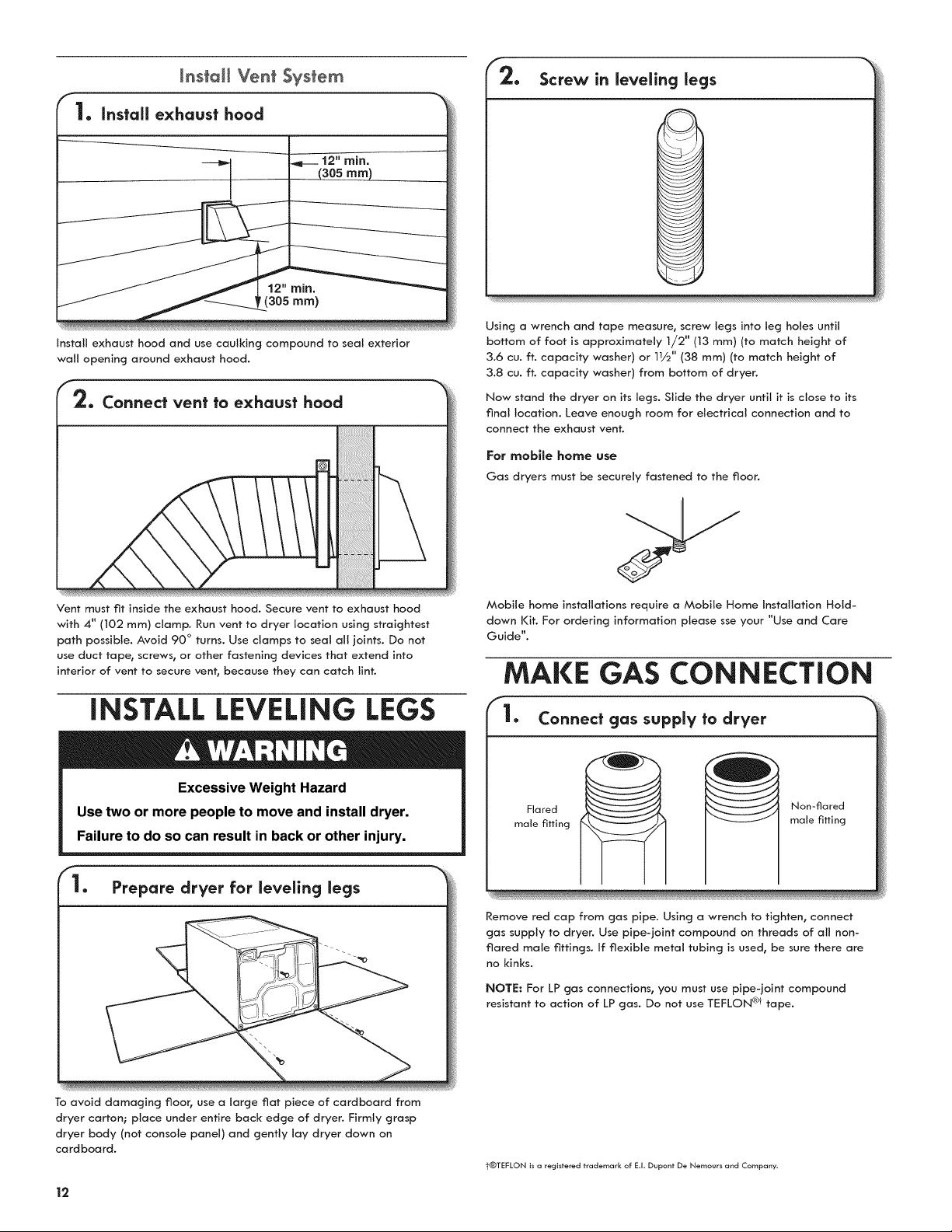
install exhaust hood and use caulking compound to seal exterior
wall opening around exhaust hood.
2. Connect vent to exhaust hood
Vent must fit inside the exhaust hood. Secure vent to exhaust hood
with 4" (102 ram) clamp. Run vent to dryer location using straightest
path possible. Avoid 90 ° turns. Use clamps to seal all joints. Do not
use duct tape, screws, or other fastening devices that extend into
interior of vent to secure vent, because they can catch lint.
INSTALL LEVELING LEGS
Excessive Weight Hazard
Use two or more people to move and install dryer.
Failure to do so can result in back or other injury.
Prepare dryer for leveling legs
Screw in leveling legs
Using a wrench and tape measure, screw legs into leg holes until
bottom of foot is approximately 1/2" (13 mm) (to match height of
3.6 cu. ft. capacity washer) or 11/2'' (38 mm) (to match height of
3.8 cu. ft. capacity washer) from bottom of dryer.
Now stand the dryer on its legs. Slide the dryer until it is close to its
final location. Leave enough room for electrical connection and to
connect the exhaust vent.
For mobffe home use
Gas dryers must be securely fastened to the floor.
Mobile home installations require a Mobile Home installation Hold-
down Kit. For ordering information please sse your "Use and Care
Guide".
MAKE GAS CONNECTION
• Connect gas supply to dryer
Flared
male fitting
Non-flared
male fitting
Remove red cap from gas pipe. Using a wrench to tighten, connect
gas supply to dryer. Use pipe-joint compound on threads of all non-
flared male fittings. If flexible metal tubing is used, be sure there are
no kinks.
NOTE: For LP gas connections, you must use pipe-joint compound
resistant to action of LP gas. Do not use TEFLON @ tape.
To avoid damaging floor, use a large flat piece of cardboard from
dryer carton; place under entire back edge of dryer. Firmly grasp
dryer body (not console panel) and gently lay dryer down on
cardboard.
t®TEFLON is a registered trademark of E.I. Dupont De Nemours and Company.
12

2. Plan pipe fitting connection
g ¸
A. 3/8" flexible gas connector
B. 3/8" dryer pipe
C
Co 3/8" to 3/8" pipe elbow
D. 3/8" pipe-to-flare adapter fitting
A combination of pipe fittings must be used to connect dryer
to existing gas line. A recommended connection is shown. Your
connection may be different, according to supply line type, size,
and location.
3. Open shut=off valve
Closed valve
Open valve
Open shut-off valve in supply line; valve is open when handle is
parallel to gas pipe. Then, test all connections by brushing on an
approved noncorrosive leak-detection solution. Bubbles will show a
leak. Correct any leaks found.
CONNECT VENT
Using a 4" (102 mm) clamp, connect vent to exhaust outlet
in dryer, if connecting to existing vent, make sure vent is clean. Dryer
vent must fit over dryer exhaust outlet and exhaust hood. Check that
vent is secured to exhaust hood with a 4" (102 mm) clamp.
Move dryer to final location. Avoid crushing or kinking vent. After
dryer is in place, remove cardboard from under the dryer.
LEVELDRYER
1. keveJ dryer
Place level here Place level here
Check levelness of dryer from side to side. Repeat from front to back.
NOTE: The dryer must be level for the moisture sensing system to
operate correctly.
Not Level LEVEL Not Level
2. Adjust leveling legs
if dryer is not level or the same height as the washer, prop up using a
wood block. Use wrench to adjust legs up or down, and check again
for levelness. Once legs are level, make sure all four legs are snug
against the floor before tightening them.
13
COMPLETE iNSTALLATiON
CHECKLIST
[_ Check that all parts are now installed. If there is an extra part, go
back through steps to see what was skipped.
[_ Check that you have all of your tools.
[_ Dispose of/recycle all packaging materials.
[_ Check dryer's final location. Be sure vent is not crushed or kinked.
[_ Check that dryer is level. See '"Level Dryer _".
[_ Remove film on console and any tape remaining on dryer.
[_ Wipe dryer drum interior thoroughly with a damp cloth to remove
any dust.
[_ Read "Dryer Use _ in your "Use and Care Guide".
[_ Set the dryer on a full heat cycle (not an air cycle) for 20 minutes
and start the dryer.
If the dryer wlll not start, check the following:
[] Dryer is plugged into a grounded 3 prong outlet.
[] Electrical supply is connected.
[] Household fuse is intact and tight, or circuit breaker
has not tripped.
[] Dryer door is closed.
[_ When the dryer has been running for 5 minutes, open the dryer door
and feel for heat. If you feel heat, cancel cycle and close the door.
If you do not feel heat, turn the dryer off: and check
to see whether gas supply line shutoff: valve is open.
[] If the gas supply line shutoff: valve is closed, open
it, then repeat the 5-minute test as outlined above.
[] If the gas supply line shutoff: valve is open, contact
a qualified technician.
NOTE: You may notice an odor when the dryer is first heated. This odor is
common when the heating element is first used. The odor will go away.
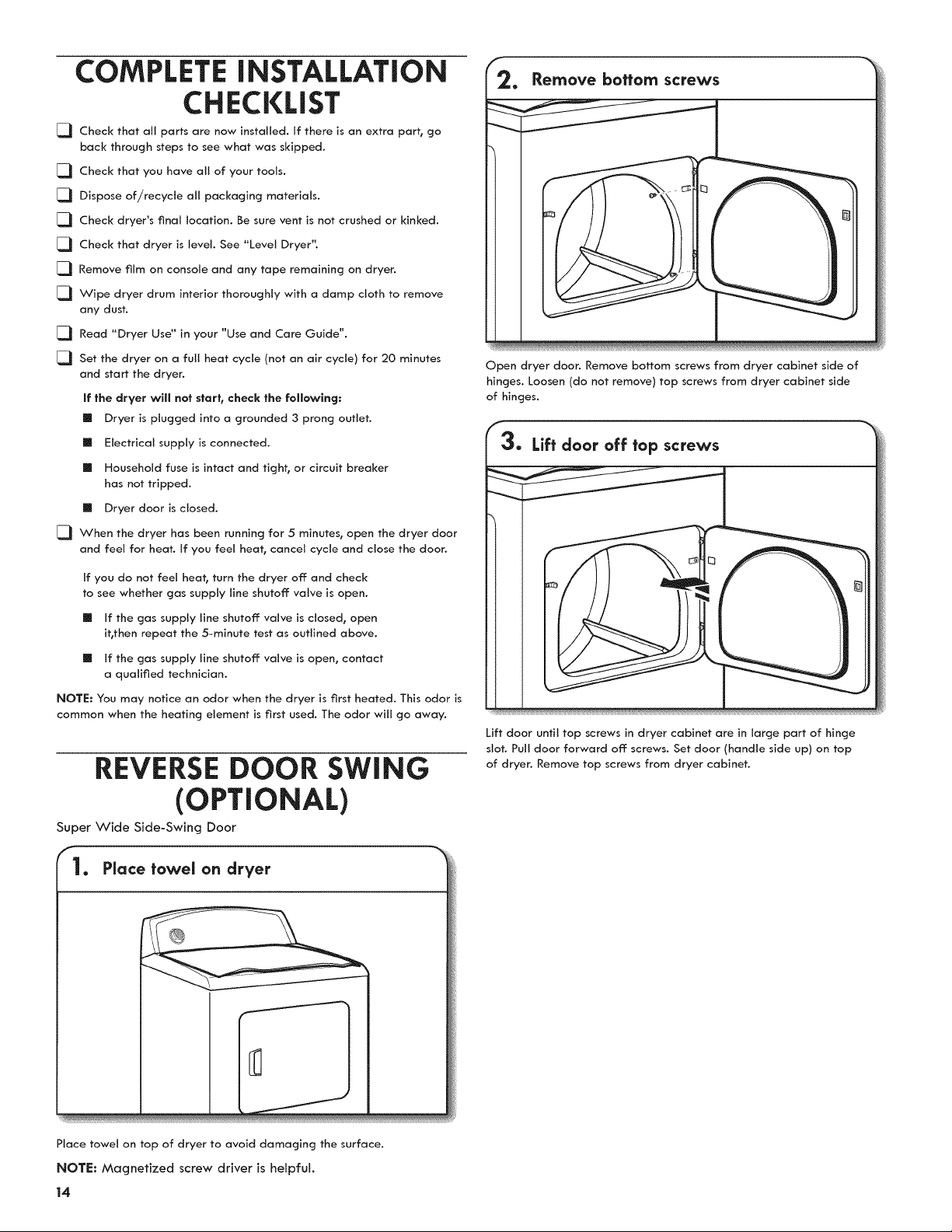
REVERSE DOOR SWING
(OPTIONAL)
Super Wide Side-Swing Door
1. Place towel on dryer
Remove bottom screws
Open dryer door. Remove bottom screws from dryer cabinet side of
hinges. Loosen (do not remove) top screws from dryer cabinet side
of hinges.
Lift door until top screws in dryer cabinet are in large part of hinge
slot. Pull door forward off: screws. Set door (handle side up) on top
of dryer. Remove top screws from dryer cabinet.
Place towel on top of dryer to avoid damaging the surface.
NOTE: Magnetized screw driver is heJpfuk
14

4. Remove screws from hinges
\
7. Rotate outer door
Rotate outer door 180 ° and set it back down on inner door. Reattach
outer door panel to inner door panel so handle is on the side where
hinges were just removed. Insert 4 door screws.
Remove screws attaching hinges to door.
5. Remove screws from door
Remove screws at top, bottom, and side of door (4 screws) that hold
the inner and outer door together. Holding door over towel on dryer,
grasp sides of outer door and lift to separate it from inner door. Set
outer door aside.
NOTE: Do not pry apart with putty knife or screwdriver. Do not pull
on door seal or plastic door catches.
F
6. Switch door catch, bezel, & plug
f
Catch and bezel Plug
Remove the door catch, bezel, and plug from the inside of the inner
door by squeezing and pulling/pushing them. Place the door catch,
bezel, and plug on the sides opposite from where they were.
8. Rip door over
Flip door over so handle side is down.
f
9. Attach door hinges
Reattach door hinges to dryer door so that the larger hole is at the
bottom of the hinge.
15

13. Check door strike alignment
Remove door strike and door strike plug from dryer cabinet. Insert
the door strike into door strike plug hole and secure with screw. Insert
door strike plug into original door strike hole and secure with screw.
Remove and transfer hinge hole plugs
Close door and check that door strike aligns with door catch. If it is
needed, slide door catch left or right within slot to adjust alignment.
TROUBLESHOOTING
See the "Use and Care Guide" or visit our website and reference
Frequently Asked Questions to possibly avoid the cost of a service call.
Use a small, fiat-blade screwdriver to gently remove 4 hinge hole
plugs on left side of dryer cabinet. Transfer plugs into hinge holes on
opposite side of dryer cabinet.
Insert screws in hinge holes on dryer
cabinet
NOTE: Two people may be needed to reinstall door.
Insert screws into the bottom holes on left side of dryer cabinet.
Tighten screws halfway. Position door so large end of door hinge slot
is over screws. Slide door up so screws are in bottom of slots. Tighten
screws. Insert and tighten top screws in hinges.
16
 Loading...