

Page 1
“The Right Control for Your Application.”
KB Electronics, Inc. www.KBelectronics.com
SIVFR Signal Isolator and Run/Fault Relay (Part No 9597)
SIVFR Signal Isolator and Run/Fault Relay (Part No 9597)
SIVFR Signal Isolator and Run/Fault Relay (Part No 9597)SIVFR Signal Isolator and Run/Fault Relay (Part No 9597)
Supplemental Information for Installation and Operation Manual Part No. A40264
Supplemental Information for Installation and Operation Manual Part No. A40264
Supplemental Information for Installation and Operation Manual Part No. A40264Supplemental Information for Installation and Operation Manual Part No. A40264
12095 NW 39 Street, Coral Springs, FL 33065-2516
Telephone: 954-346-4900; Fax: 954-346-3377
The SIVFR is Designed to be Used with the Following KBVF 2G Series Drives
KBVF-13 (Part No. 9957), KBVF-23 (Part No. 9958), KBVF-23D (Part No. 9959),
KBVF-14 (Part No. 9977), KBVF-24 (Part No. 9978), KBVF-24D (Part No. 9979),
Notes: 1. Models KBVF-45 (Part No. 9590) and KBVF-48 (Part No. 9592) contain a built-in SIVFR. 2. The software
revision code is printed on the right side of the 2.25” X ⅜” silver “WARNING: HIGH VOLTAGE!” label, which is located on
the top of the KBVF heat sink. The revision code is given in the format “XX/1.47”.
IMPORTANT:
IMPORTANT: The following information and instructions are to be used as a supplement to the SIVF Installation and Operation Manual
IMPORTANT:IMPORTANT:
(Part No A40264). The SIVF and KBVF manuals must be read and understood before attempting to operate this control. For further
assistance, contact our Sales Department at 954-346-4900 or Toll Free at 800-221-6570 (outside Florida).
The KBVF and SIVFR have been changed to second generation versions (2G). The General Performance Specifications have not changed.
The SIVFR contains a Run/Fault Relay which can be used to turn on or off equipment or to signal a warning if the drive is put into the Stop
Mode or if a fault has occurred, as described in Section 4, on pages 7 and 8.
W ARNING! High voltage is present while LEDs are illuminated. Before wiring the SIVFR to the KBVF, disconnect all power to the
KBVF and wait until the "PWR" and "ST" LEDs are no longer illuminated.
Notes: 1. Do not mount the SIVFR onto the KBVF until the ribbon cable is properly routed and installed. See Sections 1.1 – 1.4, on pages
2 – 4. 2. Do not install the enclosure cover until the SIVFR is mounted onto the KBVF and all wiring on the SIVFR is complete. See Sections
1.5 and 1.6, on pages 4 and 5. 3. For added protection, a break-away finger-safe panel is provided to close the exposed area of the SIVFR
between Terminal Blocks TB1 and TB2. See Section 5, on page 8. 4. Jumper J5 is factory set to the “NDBM” position for operation without
the optional Dynamic Brake Module installed with the KBVF. If using a Dynamic Brake Module, set Jumper J5 to the “DBM” position. See
Figure 1.
KBVF-26D (Part No. 9496), KBVF-27 (Part No. 9591), KBVF-29 (Part No. 9593).
SIVFR Signal Isolator and Run/Fault Relay PC Board, Interconnecting Ribbon Cable,
Enclosure Base, Enclosure Cover, Breakaway Finger-Safe Panel, and Mounting Screws.
(for KBVF 2G Software Revision Codes 1.47 or Higher Only)
KBVF-21D (Part No. 9581), KBVF-22D (Part No. 9572),
Kit Includes
Kit Includes
Kit IncludesKit Includes
2
1
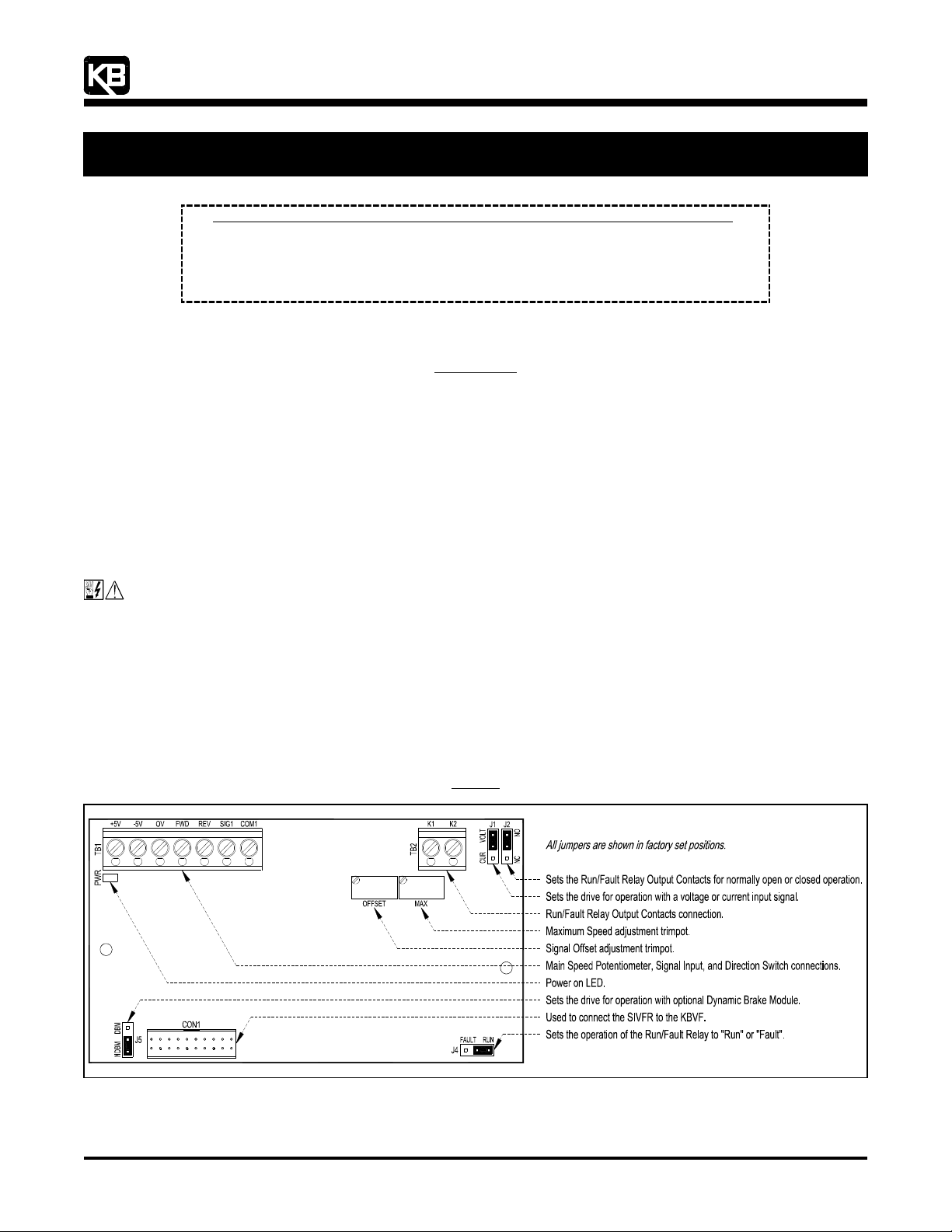
Figure 1
SIVFR Layout
(A42132) – Rev. B01 – 9/18/2006 – Z3017B01 Page 1 of 8
Page 2
“The Right Control for Your Application.”
KB Electronics, Inc. www.KBelectronics.com
SIVFR Signal Isolator and Run/Fault Relay (Part No 9597)
SIVFR Signal Isolator and Run/Fault Relay (Part No 9597)
SIVFR Signal Isolator and Run/Fault Relay (Part No 9597)SIVFR Signal Isolator and Run/Fault Relay (Part No 9597)
Supplemental Information for Installation and Operation Manual Part No. A40264
Supplemental Information for Installation and Operation Manual Part No. A40264
Supplemental Information for Installation and Operation Manual Part No. A40264Supplemental Information for Installation and Operation Manual Part No. A40264
1111 INSTALLATION INSTRUCTIONS
INSTALLATION INSTRUCTIONS
INSTALLATION INSTRUCTIONSINSTALLATION INSTRUCTIONS
WARNING! High voltage is present while LEDs are illuminated. Before wiring the SIVFR to the KBVF, disconnect all power to the
KBVF and wait until the "PWR" and "ST" LEDs are no longer illuminated.
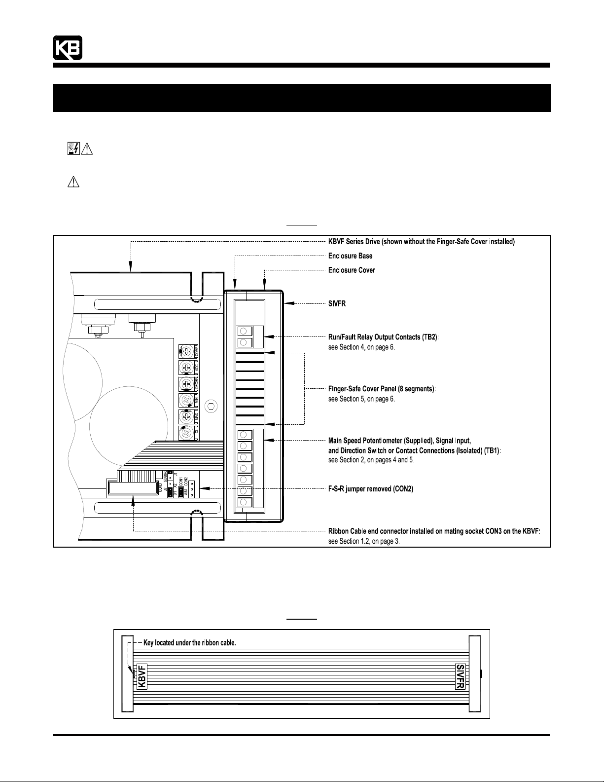
CAUTION! Before wiring and mounting the SIVFR, remove the jumper that is installed on CON2 (F-S-R) on the KBVF. Since
this jumper selects motor direction, removing it will prevent the motor from rotating, should the ribbon cable ever be
inadvertently disconnected while the drive is running. See Figure 2.
12095 NW 39 Street, Coral Springs, FL 33065-2516
Telephone: 954-346-4900; Fax: 954-346-3377
SIVFR Installation Diagram
F- S- R
Figure 2
1.1 RIBBON CABLE: Notice the location of the keys and labels on each end connector of the ribbon cable, as shown in Figure 3. The
end connector labeled “KBVF” installs into the mating socket on the KBVF (CON3), as described in Section 1.2, on page 3. The end
connector labeled “SIVFR” installs into the mating socket on the SIVFR (CON1), as described in Section 1.4, on page 4.
Figure 3
Ribbon Cable
(A42132) – Rev. B01 – 9/18/2006 – Z3017B01 Page 2 of 8
Page 3
“The Right Control for Your Application.”
KB Electronics, Inc. www.KBelectronics.com
SIVFR Signal Isolator and Run/Fault Relay (Part No 9597)
SIVFR Signal Isolator and Run/Fault Relay (Part No 9597)
SIVFR Signal Isolator and Run/Fault Relay (Part No 9597)SIVFR Signal Isolator and Run/Fault Relay (Part No 9597)
Supplemental Information for Installation and Operation Manual Part No. A40264
Supplemental Information for Installation and Operation Manual Part No. A40264
Supplemental Information for Installation and Operation Manual Part No. A40264Supplemental Information for Installation and Operation Manual Part No. A40264
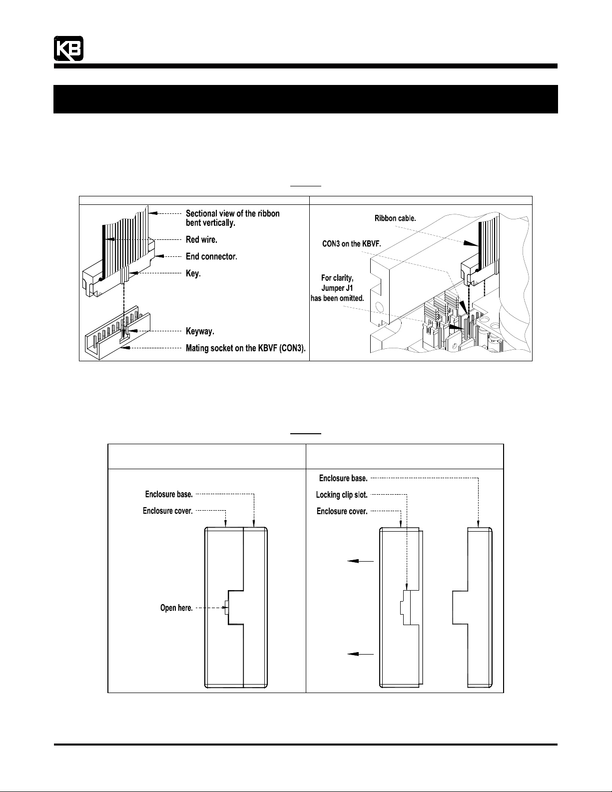
1.2 INSTALLING THE RIBBON CABLE ON THE KBVF: Bend the ribbon cable at the end connector labeled “KBVF” so it is in the
vertical position with the end connector facing down, as shown in Figure 4. Hold the ribbon cable to guide the end connector into
the mating socket CON3 on the KBVF. Using the insulated trimpot adjustment tool (supplied with the KBVF), gently press on the
end connector to fully engage it into the mating socket. Also see Figure 2, on page 2.
12095 NW 39 Street, Coral Springs, FL 33065-2516
Telephone: 954-346-4900; Fax: 954-346-3377
Ribbon Cable and CON3 Expanded View of the KBVF
Installing the Ribbon Cable on CON3 on the KBVF
1.3 REMOVING THE ENCLOSURE COVER: Insert a small flat blade screwdriver into the slots located on both sides of the enclosure
cover, as shown in Figure 5. Gently pry off the enclosure cover. The SIVFR should be properly positioned in the enclosure base,
as described in Section 1.5, on page 4.
Removing the Enclosure Cover
Enclosure Cover Engaged
with Enclosure Base
Figure 4
Figure 5
Enclosure Cover Disengaged
from Enclosure Base
(SIVFR PC Board Omitted for Clarity)
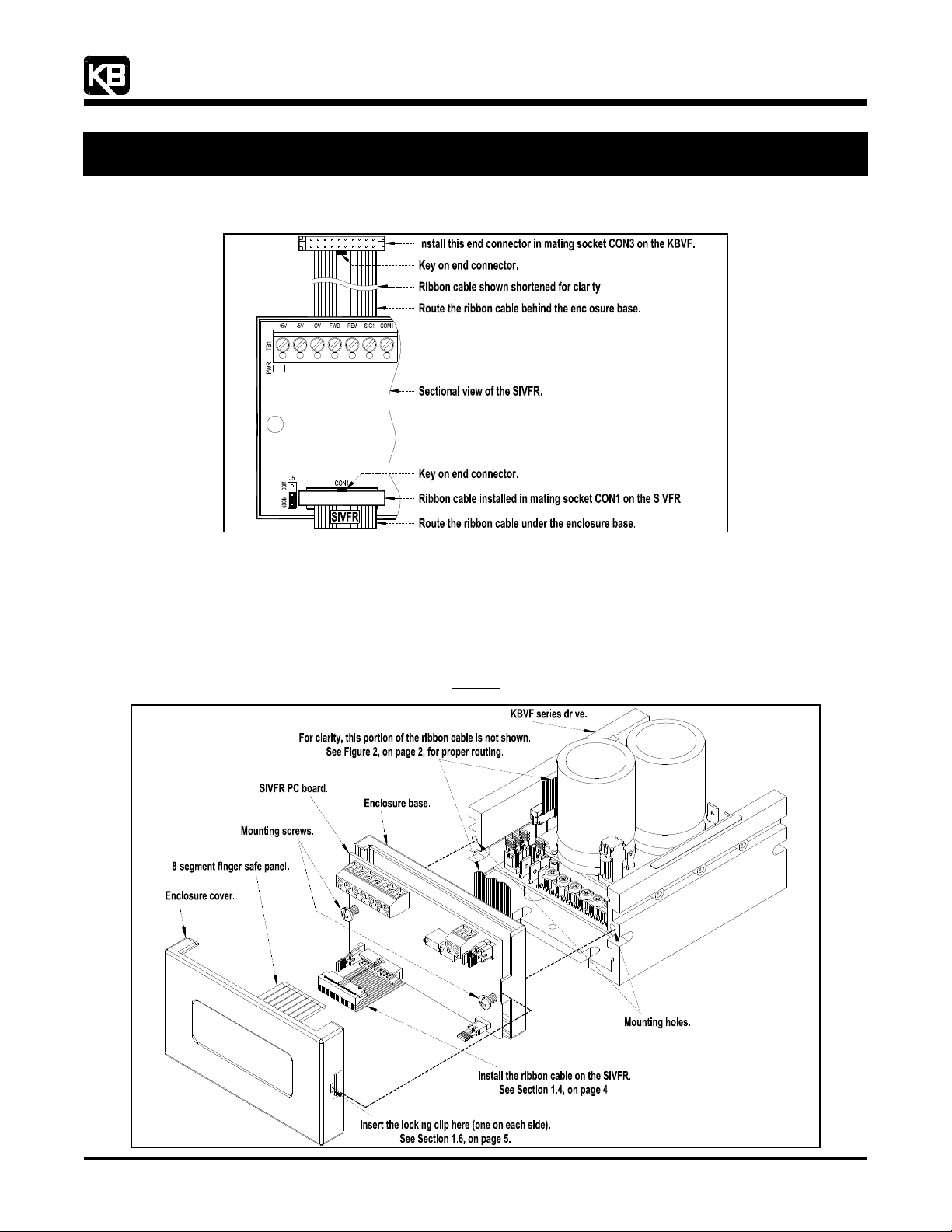
1.4 INSTALLING THE RIBBON CABLE ON THE SIVFR: Install the end connector labeled “SIVFR” into the mating socket CON1 on
the SIVFR, as shown in Figure 6. The ribbon cable must be routed under and behind the enclosure base. It must lay flat (not
twisted) along the back of the enclosure base.
(A42132) – Rev. B01 – 9/18/2006 – Z3017B01 Page 3 of 8
Page 4
“The Right Control for Your Application.”
KB Electronics, Inc. www.KBelectronics.com
SIVFR Signal Isolator and Run/Fault Relay (Part No 9597)
SIVFR Signal Isolator and Run/Fault Relay (Part No 9597)
SIVFR Signal Isolator and Run/Fault Relay (Part No 9597)SIVFR Signal Isolator and Run/Fault Relay (Part No 9597)
Supplemental Information for Installation and Operation Manual Part No. A40264
Supplemental Information for Installation and Operation Manual Part No. A40264
Supplemental Information for Installation and Operation Manual Part No. A40264Supplemental Information for Installation and Operation Manual Part No. A40264
12095 NW 39 Street, Coral Springs, FL 33065-2516
Telephone: 954-346-4900; Fax: 954-346-3377
Ribbon Cable Installed on the SIVFR
1.5 MOUNTING THE SIVFR: Be sure the SIVFR PC board is properly seated and oriented in the enclosure base. The mounting holes
on the SIVFR PC board must align with the mounting holes on the enclosure base. Do not install the enclosure cover until all wiring
on the SIVFR is complete.
Align the SIVFR assembly mounting holes with the mounting holes located on the trimpot side of the KBVF heat sink. Insert the
two 6-32 X ½” combination head screws (provided), through the SIVFR assembly. Use a Philips or flat blade screwdriver to tighten
the screws and secure the SIVFR to the KBVF. Do not overtighten the screws. See Figure 7. Also see Figure 2, on page 2.
Figure 6
Figure 7
Mounting the SIVFR
(A42132) – Rev. B01 – 9/18/2006 – Z3017B01 Page 4 of 8
Page 5
“The Right Control for Your Application.”
12095 NW 39 Street, Coral Springs, FL 33065-2516
Telephone: 954-346-4900; Fax: 954-346-3377
KB Electronics, Inc. www.KBelectronics.com
SIVFR Signal Isolator and Run/Fault Relay (Part No 9597)
SIVFR Signal Isolator and Run/Fault Relay (Part No 9597)
SIVFR Signal Isolator and Run/Fault Relay (Part No 9597)SIVFR Signal Isolator and Run/Fault Relay (Part No 9597)
Supplemental Information for Installation and Operation Manual Part No. A40264
Supplemental Information for Installation and Operation Manual Part No. A40264
Supplemental Information for Installation and Operation Manual Part No. A40264Supplemental Information for Installation and Operation Manual Part No. A40264
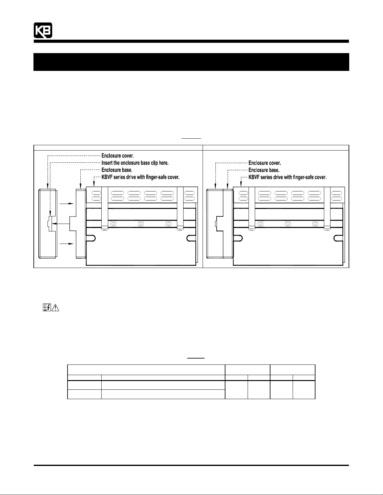
1.6 INSTALLING THE ENCLOSURE COVER: After all wiring is complete and the SIVFR is properly mounted onto the KBVF, install the
enclosure cover. See Section 5, on page 8, for installing the finger-safe panel.
Orient the enclosure cover such that the label is upright (and the wider opening of the enclosure cover is at the top). Align both clips
on the enclosure base with both slots on the enclosure cover. Gently push on the enclosure cover until both clips are fully engaged.
See Figure 8.
Note: Be sure the “handles” of Jumpers J1, J2, J4, J5 remain inside the enclosure and they do not get crimped while installing the enclosure cover.
Installing the Enclosure Cover
Figure 8
SIVFR Mounted Onto the KBVF Enclosure Cover Installed Onto the SIVFR
2222 WIRING INSTRUCTIONS
WIRING INSTRUCTIONS
WIRING INSTRUCTIONSWIRING INSTRUCTIONS
See Table 1, for the wire size and recommended tightening torque for Terminal Blocks TB1 and TB2 on the SIVFR.
WARNING! Read Safety Warning, on page 1 of the SIVF manual, before using the drive. Disconnect main power when
making connections to the drive.
Application Note: To avoid erratic operation, do not bundle the AC line and motor wires together or with wires from signal following,
start/stop contacts, or any other signal wires. Also, do not bundle motor wires from multiple drives in the same conduit. Use shielded
cables on all signal wiring over 12" (30 cm). The shield should be earth grounded on the drive side only. Wire the drive in accordance
with the National Electrical Code requirements and other local codes that may apply.
Table 1
Terminal Block Wiring Information
Designation Description AWG mm
Terminal Block
TB1 Main Speed Potentiometer, Signal Input, and Direction Switch
TB2 Run/Fault Relay Output Contacts
Maximum
Wire Size (Cu)
16 1.3 3.5 4
Recommended
Tightening Torque
2
in-lbs kg-cm
(A42132) – Rev. B01 – 9/18/2006 – Z3017B01 Page 5 of 8
Page 6
“The Right Control for Your Application.”
KB Electronics, Inc. www.KBelectronics.com
SIVFR Signal Isolator and Run/Fault Relay (Part No 9597)
SIVFR Signal Isolator and Run/Fault Relay (Part No 9597)
SIVFR Signal Isolator and Run/Fault Relay (Part No 9597)SIVFR Signal Isolator and Run/Fault Relay (Part No 9597)
Supplemental Information for Installation and Operation Manual Part No. A40264
Supplemental Information for Installation and Operation Manual Part No. A40264
Supplemental Information for Installation and Operation Manual Part No. A40264Supplemental Information for Installation and Operation Manual Part No. A40264
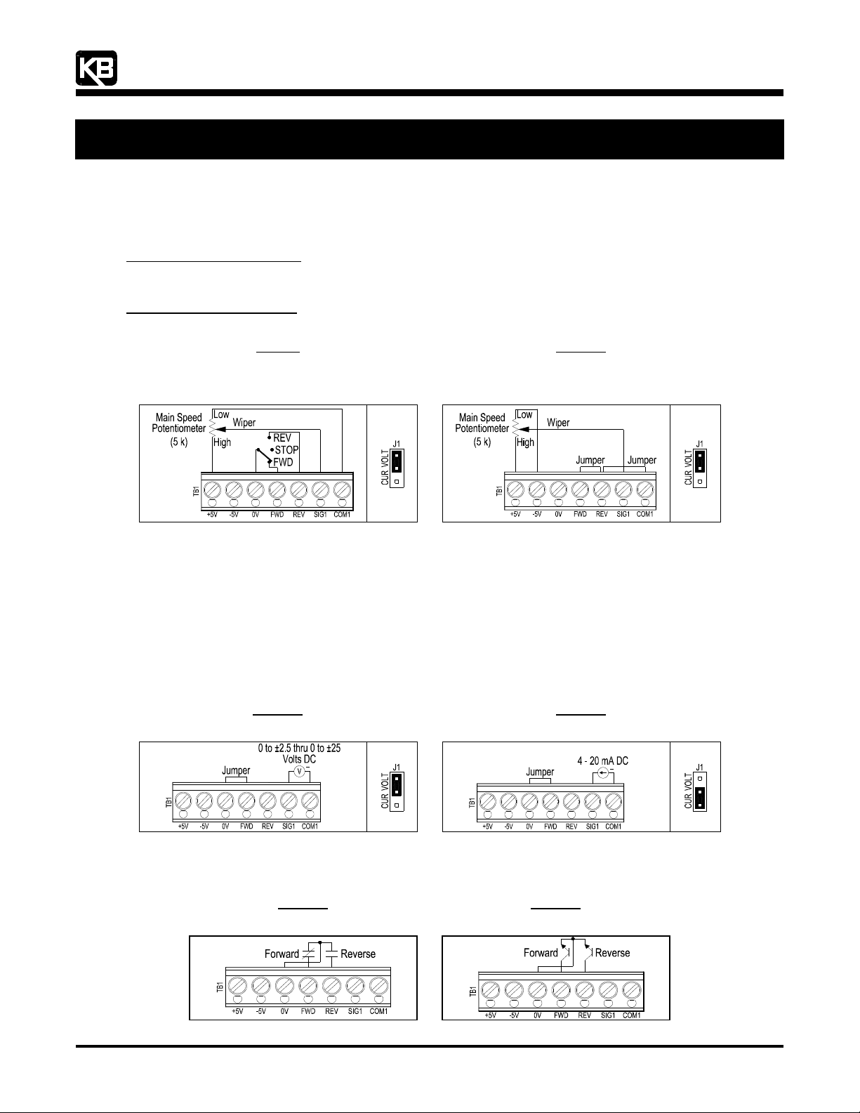
2.1 MAIN SPEED POTENTIOMETER CONNECTION:
Wire the Main Speed Potentiometer to Terminal Block TB1 on the SIVFR. See Section 2.3, on page 6, for Forward-Stop-Reverse
Switch (or Jumper) connection. If a Forward-Stop-Reverse Switch is not used, a jumper must be installed between Terminals “0V”
and “FWD”, of Terminal Block TB1, in order for the drive to operate.
Unidirectional Speed Operation: Wire the Main Speed Potentiometer to Terminals “+5V” (high), “SIG1” (wiper), “COM1” (low).
Motor direction is selected with a Forward-Stop-Reverse Switch wired to Terminals “0V” (common of switch), “FWD”, “REV”. Set
Jumper J1 to the “VOLT” position. See Figure 9.
Bidirectional Speed Operation: Wire the Main Speed Potentiometer to Terminals “+5V” (high), “SIG1” (wiper), “-5V” (low).
Terminals “FWD”, “REV”, “COM1” must be hard wired together. Set Jumper J1 to the “VOLT” position. See Figure 10.
12095 NW 39 Street, Coral Springs, FL 33065-2516
Telephone: 954-346-4900; Fax: 954-346-3377
Figure 9
Unidirectional
and Forward-Stop-Reverse Switch Connections
Main Speed Potentiometer
(J1 Installed in “VOLT” Position)
2.2 SIGNAL FOLLOWING CONNECTION: The drive output will linearly follow the analog signal input. The SIVFR is factory calibrated
for 0 to ±5 Volt DC signal input. Wire the voltage (0 to ±2.5 thru 0 to ±25 Volt DC) or current (4 – 20 mA DC) signal input to
Terminals “SIG1” (+) and “COM1” (-) of Terminal Block TB1 on the SIVFR. A jumper must be installed between Terminals “0V” and
“FWD”, of Terminal Block TB1, in order for the drive to operate.
For voltage following, be sure Jumper J1 (on the SIVFR) is set to the “VOLT” position (factory setting). See Figure 11.
Application Note: In the Voltage Following Mode, the input will accept a “+” and “-“ input voltage, which will run the motor in the
forward and reverse direction.
For current following, set Jumper J1 (on the SIVFR) to the “CUR” position. See Figure 12. Also See Section 3.2, on page 7.
Figure 11
Voltage Following Signal Input Connection
(J1 Installed in “VOLT” Position)
Main Speed Potentiometer Connection
(Terminals “FWD”, “REV”, “COM1” Hardwired)
(J1 Installed in “VOLT” Position)
Current Following Signal Input Connection
(J1 Installed in “CUR” Position)
Figure 10
Bidirectional
Figure 12
+
2.3 FORWARD-STOP-REVERSE SWITCH CONNECTION: Wire the Forward-Stop-Reverse Switch as shown in Figure 9. If using
Form “C” Contact or Relay, wire the circuit as shown in Figure 13. If using Open Collector, wire the circuit as shown in Figure 14.
Form “C” Contact or Relay
Forward-Stop-Reverse Connection
(A42132) – Rev. B01 – 9/18/2006 – Z3017B01 Page 6 of 8
Figure 13
Forward-Stop-Reverse Connection
Figure 14
Open Collector
+
Page 7
“The Right Control for Your Application.”
12095 NW 39 Street, Coral Springs, FL 33065-2516
Telephone: 954-346-4900; Fax: 954-346-3377
KB Electronics, Inc. www.KBelectronics.com
SIVFR Signal Isolator and Run/Fault Relay (Part No 9597)
SIVFR Signal Isolator and Run/Fault Relay (Part No 9597)
SIVFR Signal Isolator and Run/Fault Relay (Part No 9597)SIVFR Signal Isolator and Run/Fault Relay (Part No 9597)
Supplemental Information for Installation and Operation Manual Part No. A40264
Supplemental Information for Installation and Operation Manual Part No. A40264
Supplemental Information for Installation and Operation Manual Part No. A40264Supplemental Information for Installation and Operation Manual Part No. A40264
3333 TRIMPOT ADJUSTMENTS
TRIMPOT ADJUSTMENTS
TRIMPOT ADJUSTMENTSTRIMPOT ADJUSTMENTS
The SIVFR contains multi-turn trimpots which are factory set for most applications. See Figure 1, on page 1, for the location of the
trimpots.
The SIVFR is factory set for Voltage Following Operation to run the motor from zero speed to full speed with a 0 to ±5 Volt DC analog
signal input. For Current Following Operation (4 – 20 mA DC), see Section 3.2.
Some applications may require readjustment of the trimpots in order to tailor the drive for a specific application. The trimpots may be
readjusted as described below.
WARNING! If possible, do not adjust trimpots with the main power applied. If adjustments are made with the main
power applied, an insulated adjustment tool must be used and safety glasses must be worn. High voltage exists in this drive.
Fire and/or electrocution can result if caution is not exercised. Safety Warning, on page 1 of the SIVF manual, must be read and
understood before proceeding.
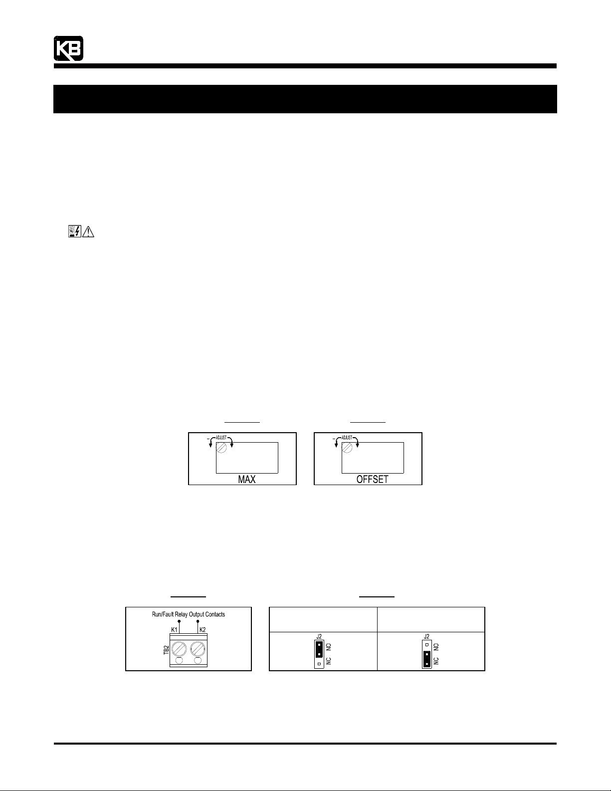
3.1 MAXIMUM SPEED (MAX): The MAX Trimpot is factory set to run the motor at full speed with a ±5 Volt DC analog signal input. For
a higher analog signal input (±25 Volt DC max.) rotate the MAX Trimpot counterclockwise. For a lower analog signal input (±2.5 Volt
DC min.) rotate the MAX Trimpot clockwise. See Figure 15.
Note: The MAX Trimpot on the KBVF has been factory set to an Upper Frequency Limit of 60 Hz (50 Hz, for 50 Hz motors). If the
application requires a slightly higher maximum frequency (up to 66 Hz), rotate the MAX Trimpot on the KBVF to full clockwise
position.
3.2 SIGNAL OFFSET (OFFSET): The OFFSET Trimpot is used to recalibrate the drive for Current Following Operation. The SIVFR will
run the motor from zero speed to full speed with a 4 – 20 mA DC analog signal input. For a higher minimum speed setting, rotate
the OFFSET trimpot clockwise. For a lower minimum speed setting rotate the OFFSET Trimpot counterclockwise. See Figure 16.
Note: The MIN Trimpot on the KBVF is not functional when the SIVFR is installed.
4444 RUN/FAULT RELAY
RUN/FAULT RELAY
RUN/FAULT RELAYRUN/FAULT RELAY
Figure 15
Maximum Speed Trimpot
+
Figure 16
Offset Trimpot
+
The Run/Fault Relay Output Contacts are located at TB2 of the SIVFR and can be used to turn on or off equipment or to signal a warning
if the drive is put into the Stop Mode or if a fault has occurred. See Figure 17.
See Table 2 for the drive operating condition and Run/Fault Relay Contact status.
For normally open contact, set Jumper J2 on the SIVFR to the “NO” position. For normally closed contact, set Jumper J2 on the SIVFR to
the “NC” position. See Figure 18.
Run/Fault Relay Connection
Figure 17
Run/Fault Relay Output Contact Selection
Normally Open Contact
(J2 Installed in “NO” Position)
(Factory Setting)
Figure 18
Normally Closed Contact
(J2 Installed in “NC” Position)
(A42132) – Rev. B01 – 9/18/2006 – Z3017B01 Page 7 of 8
Page 8
“The Right Control for Your Application.”
12095 NW 39 Street, Coral Springs, FL 33065-2516
Telephone: 954-346-4900; Fax: 954-346-3377
KB Electronics, Inc. www.KBelectronics.com
SIVFR Signal Isolator and Run/Fault Relay (Part No 9597)
SIVFR Signal Isolator and Run/Fault Relay (Part No 9597)
SIVFR Signal Isolator and Run/Fault Relay (Part No 9597)SIVFR Signal Isolator and Run/Fault Relay (Part No 9597)
Supplemental Information for Installation and Operation Manual Part No. A40264
Supplemental Information for Installation and Operation Manual Part No. A40264
Supplemental Information for Installation and Operation Manual Part No. A40264Supplemental Information for Installation and Operation Manual Part No. A40264
Drive Operating Condition and Run/Fault Relay Contact Status
Table 2
Run Relay Operation
(J4 Installed in “RUN” Position)
Drive
Operating Condition
Power Off
(Main Power Disconnected)
Run Mode*
(Normal Drive Operation)
Stop Mode*
(Selected by Operator)
Fault**
(Drive Tripped)
*Run Mode or Stop Mode is selected using the Forward-Stop-Reverse Switch. **Fault: Overload, I2t, Short Circuit, Undervoltage, and Overvoltage.
5555 OPTIONAL FINGER-SAFE PANEL
OPTIONAL FINGER-SAFE PANEL
OPTIONAL FINGER-SAFE PANELOPTIONAL FINGER-SAFE PANEL
J2 Installed in “NO” Position
(Factory Setting)
Open Closed Open Closed
Closed Open Closed Open
Open Closed Closed Open
Open Closed Open Closed
(Factory Setting)
Relay Contact Status (Terminals K1 and K2 of TB2)
J2 Installed in “NC” Position
J2 Installed in “NO” Position
(J4 Installed in “FAULT” Position)
(Factory Setting)
Fault Relay Operation
J2 Installed in “NC” Position
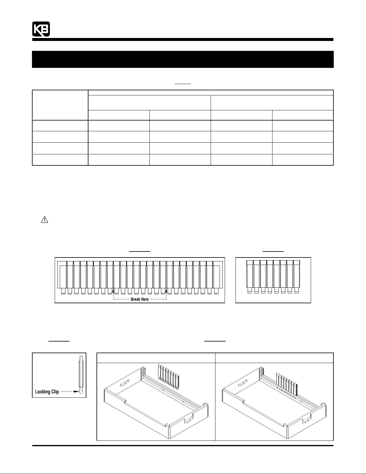
The SIVFR is supplied with a finger-safe panel which may be used with the enclosure cover to close the unused exposed area of the
SIVFR between Terminal Blocks TB1 and TB2. The finger-safe panel is a 24-segment panel. Only an 8-segment piece is needed for the
SIVFR. The finger-safe panel may be separated into three equal size pieces. See Figure 19.
WARNING! Use caution and wear eye protection when snapping off or cutting off sections of the finger-safe panel.
5.1 Segmenting the Finger-Safe Panel: By bending the finger-safe panel back and forth at the breakaway points, snap off an
8-segment piece (1¼” in length). See Figure 20.
24-Segment Finger-Safe Panel
Figure 19
8-Segment Finger-Safe Panel
Figure 20
5.2 Installing the 8-Segment Finger-Safe Panel: Notice the locking clip on the side view of the finger-safe panel, as shown in Figure
21. Install the 8-segment panel into the enclosure cover with the locking clip facing toward the center of the enclosure cover, as
shown in Figure 22. Also see Figure 2, on page 2.
Figure 21
Side View of the
Finger-Safe Panel
Installing the 8-Segment Finger-Safe Panel
Onto the Enclosure Cover
8-Segment Finger-Safe Panel Aligned
with the Enclosure Cover
Figure 22
8-Segment Finger-Safe Panel Installed
Onto the Enclosure Cover
(A42132) – Rev. B01 – 9/18/2006 – Z3017B01 Page 8 of 8
Page 9

INSTALLATION AND OPERATING INSTRUCTIONS
MODEL SIVF
KB Part No. 9474 – Signal Isolator for KBVF Controls
See Page 1
See Safety Warning on Page 1
The information contained in this manual is intended to be accurate. However, the manufacturer retains the
right to make changes in design which may not be included herein.
A COMPLETE LINE OF MOTOR DRIVES
© 1999 KB Electronics, Inc.
Pending
Page 10

TABLE OF CONTENTS
SECTION Page
i. Safety Warning . . . . . . . . . . . . . . . . . . . . . . . . . . . . . . . . . . . . . . . . . . . . . . . . . . . . . . . . . . . . . 1
I. Introduction . . . . . . . . . . . . . . . . . . . . . . . . . . . . . . . . . . . . . . . . . . . . . . . . . . . . . . . . . . . . . . . . 3
II. Installation Instructions . . . . . . . . . . . . . . . . . . . . . . . . . . . . . . . . . . . . . . . . . . . . . . . . . . . . . . . 4
III. Connections to the SIVF . . . . . . . . . . . . . . . . . . . . . . . . . . . . . . . . . . . . . . . . . . . . . . . . . . . . . . 9
IV. Calibration Procedure . . . . . . . . . . . . . . . . . . . . . . . . . . . . . . . . . . . . . . . . . . . . . . . . . . . . . . . 13
V. Limited Warranty . . . . . . . . . . . . . . . . . . . . . . . . . . . . . . . . . . . . . . . . . . . . . . . . . . . . . . . . . . . 18
Addendum I . . . . . . . . . . . . . . . . . . . . . . . . . . . . . . . . . . . . . . . . . . . . . . . . . . . . . . . . . . . . . . . . . . 15
TABLE
1. General Performance Specifications . . . . . . . . . . . . . . . . . . . . . . . . . . . . . . . . . . . . . . . . . . . . . 4
2. Terminal Block Wiring Information . . . . . . . . . . . . . . . . . . . . . . . . . . . . . . . . . . . . . . . . . . . . . . . 9
FIGURE
1. Control Layout . . . . . . . . . . . . . . . . . . . . . . . . . . . . . . . . . . . . . . . . . . . . . . . . . . . . . . . . . . . . . 2
2. SIVF Connection Diagram . . . . . . . . . . . . . . . . . . . . . . . . . . . . . . . . . . . . . . . . . . . . . . . . . . . . . 5
3. SIVF Mounting Diagram . . . . . . . . . . . . . . . . . . . . . . . . . . . . . . . . . . . . . . . . . . . . . . . . . . . . . . 6
4A. SIVF Mechanical Specifications (Mounted to 1/2HP KBVF) . . . . . . . . . . . . . . . . . . . . . . . . . . . . 7
4B. SIVF Mechanical Specification (Mounted to 1HP KBVF) . . . . . . . . . . . . . . . . . . . . . . . . . . . . . . 8
5. Voltage Following Connection . . . . . . . . . . . . . . . . . . . . . . . . . . . . . . . . . . . . . . . . . . . . . . . . . 10
6. Current Following Connection . . . . . . . . . . . . . . . . . . . . . . . . . . . . . . . . . . . . . . . . . . . . . . . . . 11
7. Potentiometer Connection . . . . . . . . . . . . . . . . . . . . . . . . . . . . . . . . . . . . . . . . . . . . . . . . . . . . 11
8. Unidirectional Operation . . . . . . . . . . . . . . . . . . . . . . . . . . . . . . . . . . . . . . . . . . . . . . . . . . . . . 12
9. Switch Connection . . . . . . . . . . . . . . . . . . . . . . . . . . . . . . . . . . . . . . . . . . . . . . . . . . . . . . . . . 12
10. Open Collector Connection . . . . . . . . . . . . . . . . . . . . . . . . . . . . . . . . . . . . . . . . . . . . . . . . . . . 13
11. Finger-Safe Cover . . . . . . . . . . . . . . . . . . . . . . . . . . . . . . . . . . . . . . . . . . . . . . . . . . . . . . . . . . 16
i
Page 11

i. SAFETY WARNING! PLEASE READ CAREFULLY
This product should be installed and serviced by a qualified technician, electrician or electrical
maintenance person familiar with its operation and the hazards involved. Proper installation, which
includes wiring, mounting in proper enclosure, fusing or other overcurrent protection and grounding,
can reduce the chance of electric shocks, fires or explosion in this product or products used with this
product, such as electric motors, switches, coils, solenoids and/or relays. Eye protection must be
worn and insulated adjustment tools must be used when working with control under power. This
product is constructed of materials (plastics, metals, carbon, silicon, etc.) which may be a potential
hazard. Proper shielding, grounding and filtering of this product can reduce the emission of radio
frequency interference (RFI) which may adversely affect sensitive electronic equipment. If information is required on this product, contact our factory. It is the responsibility of the equipment manufacturer and individual installer to supply this safety warning to the ultimate user of this product. (SW
effective 11/92)
This control contains electronic start/stop circuits that can be used to start and stop the control.
However, these circuits are never to be used as safety disconnects since they are not fail-safe. Use
only the AC line for this purpose.
Be sure to follow all instructions carefully. Fire and/or electrocution can result due to improper
use of this product.
This product complies with all CE directives pertinent at the time of manufacture. Contact
factory for detailed installation instructions and Declaration of Conformity.
1
Page 12

FIGURE 1 – CONTROL LAYOUT
2
Page 13

I. INTRODUCTION
Thank you for purchasing the SIVF Signal Isolator (P/N 9474). KB Electronics, Inc. is committed to providing total customer satisfaction by producing high quality products that have
been manufactured to the highest standards and techniques in the industry. The SIVF is
engineered with state-of-the-art surface mount technology (SMT) incorporating advanced
circuitry in a relatively small and user friendly package, making it convenient to operate and
easy to install.
The SIVF is used to isolate, amplify, and condition DC voltage and current signals from any
source (power supplies, motors, tachometer generators, transducers, and potentiometers).
The isolated output voltage of the SIVF provides input signals to all models of the KBVF
Adjustable Frequency Drive (P/N 9957, 9958, 9959, 9977, 9978, and 9979). Signal input
and motor direction control is performed by making connections to the on-board barrier terminal. All inputs (+5V, SIG, COM, FWD & REV) to the SIVF are isolated from the AC line
and motor connections.
The SIVF is factory calibrated to accept signal input voltage (0 – 5V DC), current (4 – 20mA
DC), or a potentiometer (5KΩ) via a jumper selection. MIN and MAX trimpots are provided
in order to readjust the SIVF. This allows the use of 0 – 2.5 thru 25V DC input voltage signals for customizing specific applications.
3
Page 14

TABLE 1 – GENERAL PERFORMANCE SPECIFICATIONS
Voltage Following Operation Input Range (V DC) . . . . . . . . . . . . . . . . . . . . . . . . . . . . . . . 0 – 2.5 thru 25
Current Following Operation Input Range (mA DC) . . . . . . . . . . . . . . . . . . . . . . . . . . . . . . . . . . . . . 4 – 20
Potentiometer Operation (KΩ) . . . . . . . . . . . . . . . . . . . . . . . . . . . . . . . . . . . . . . . . . . . . . . . . . . . . . . . . 5
Output Voltage at P2 (V DC) . . . . . . . . . . . . . . . . . . . . . . . . . . . . . . . . . . . . . . . . . . . . . . . . . . . . . . 0 – 5
MIN Trimpot Range (with 0 Volts Input) (% Full Speed) . . . . . . . . . . . . . . . . . . . . . . . . . . . . . . . . . 0 – 40
MAX Trimpot Range (with 5 Volts Input) (% Full Speed) . . . . . . . . . . . . . . . . . . . . . . . . . . . . . . . 70 – 110
FWD and REV Input Switch Types . . . . . . . . . . . . . . . . . . . . . . . . . . . . . . . Dry Contact or Open Collector
Linearity (%) . . . . . . . . . . . . . . . . . . . . . . . . . . . . . . . . . . . . . . . . . . . . . . . . . . . . . . . . . . . . . . . . . . . . 0.5
Thermal Drift (mV/ ˚C) . . . . . . . . . . . . . . . . . . . . . . . . . . . . . . . . . . . . . . . . . . . . . . . . . . . . . . . . . . . . . 1.0
Electromagnetic Compatibility (V/m at 80-1000M Hz) . . . . . . . . . . . . . . . . . . . . . . . . . . . . . . . . . . . . . . . 3
II. INSTALLATION INSTRUCTIONS
See figure 2, SIVF Connection Diagram, on page 5.
WARNING: HIGH VOLTAGE IS
PRESENT WHILE LEDs ARE ILLUMINATED.
Before wiring the SIVF to the KBVF, disconnect all power to the KBVF and wait until “PWR”
and “ST” LEDs are no longer illuminated.
A. Wiring the SIVF to the KBVF – (Note: Do not install the SIVF to the KBVF until wiring
is completed.)
1. Remove the F-S-R jumper which is installed on CONN2 of the KBVF. Attach the
3-pin connector (with white, black, and red wires) from the SIVF to the KBVF connector marked “CONN2”.
2. Attach the red wire from the SIVF to the KBVF terminal marked “J3”.
3. Attach the orange wire from the SIVF to the KBVF terminal marked “P2”.
4
Note: If the KBVF contains a finger safe cover,
(KB P/N 9473) see
Addendum I on page 15.
Page 15

FIGURE 2 – SIVF CONNECTION DIAGRAM
5
Page 16

FIGURE 3 – SIVF MOUNTING DIAGRAM
(Shown Mounted to Model KBVF-24D)
6
Page 17

FIGURE 4A – SIVF MECHANICAL SPECIFICATIONS (Inches / mm)
(Shown Mounted to 1/2HP KBVF – With Optional Finger-Safe Cover)
7
Page 18

FIGURE 4B – SIVF MECHANICAL
SPECIFICATIONS (inches / mm)
(Shown Mounted to 1HP Model KBVF)
8
Page 19

B. MOUNTING THE SIVF ONTO THE KBVF
See figure 3, SIVF Mounting Diagram.
See figures 4A and 4B, SIVF Mechanical Specifications, on pages 7 and 8.
The SIVF is installed onto the KBVF using (2) two 6-32 X 1/2” screws provided.
Note: The screws are a combination head type which allow the use of a readily avail-
able #1 or #2 phillips or slotted head screwdriver.
Note: Before installing the SIVF be sure the wiring to the KBVF has been completed.
See section II, Installation Instructions, on page 3
1. Align the SIVF mounting holes with the tapped holes on the KBVF heat sink and
insert the screws through the SIVF mounting holes.
2. Using a screwdriver, fasten both screws until the SIVF is secured to the KBVF (8
in-lbs max). Do not over tighten screws or damage may result to SIVF cover.
TABLE 2 – TERMINAL BLOCK WIRING INFORMATION
Connection
Designation
Logic Connections 24
III. CONNECTIONS TO THE SIVF
Safety Warning! Do not use FWD-STOP-REV contacts as a safety disconnect since
they are not fail-safe. Use only the AC line for this purpose.
Supply Wire Gauge
(AWG – Cu)
Minimum Maximum
14
Maximum
Tightening
Torque (in-lbs)
3.5
9
Page 20

Note: A connection must be made between FWD and COM or REV and COM in order
for control to operate. Jumper shown installed in FWD direction.
See Table 2, Terminal Block Wiring Information, on page 9.
Note: The MIN and MAX trimpots on the KBVF are non-operational after the SIVF is
installed.
A. Signal Following
In this mode, a signal source is used to vary motor speed.
i. Voltage Following – Uses a voltage
source to vary motor speed.
Figure 5 – Voltage Following Connection
(Jumper J1 in “VOLT” Position)
Set J1 to “VOLT” position and connect
the voltage source to TB1 terminals SIG (+) and COM (-). See
figure 5, Voltage Following Connection. Be sure the posi-
tive (+) signal is connected to “SIG” terminal and the
negative (-) is connected to the “COM” terminal.
When a 0V DC signal is applied, the
motor will operate at the minimum set
speed (set by the MIN trimpot on the
SIVF). When a 5V DC signal is applied, the
motor will operate at the maximum set speed (set by the MAX trimpot on the
SIVF).
ii. Current Following – Uses a current source to vary motor speed.
Set J1 to “CUR” position and connect the current source to TB1 terminals SIG
(+) and COM (-). See figure 7, Current Following Connection, on page 11.
10
Page 21

Be sure the positive (+) signal is
Figure 6 – Current Following Connection
connected to “SIG” terminal and
the negative (-) is connected to
the “COM” terminal.
When a 4mA DC signal is applied, the motor will operate
at the minimum set speed (set by the MIN trimpot on
the SIVF). When a 20mA DC signal is applied, the
motor will operate at the maximum set speed (set by
the MAX trimpot on the SIVF)
B. Potentiometer Operation – Uses a potentiome-
ter to vary motor speed.
Set J1 to “VOLT” position and connect the 5K potentiometer
to TB1 terminals marked “SIG” (wiper of
potentiometer), “+5” (high side of potentiometer), and “COM” (low side of potentiometer). See figure 7 Potentiometer
Connection. When the potentiometer is set to 0% (fully counterclock-
wise), the motor will operate at the minimum set speed (set by
the MIN trimpot on the SIVF). When the potentiometer is
set to 100% (full clockwise position) the motor will operate
at full speed (set by the MAX trimpot on the SIVF).
(Jumper J1 in “CUR” Position)
Figure 7 – Potentiometer Connection
(Jumper J1 in “VOLT” Position)
C. Unidirectional Operation
To operate the control in forward, install a
jumper between “FWD” and “COM” terminals of
the SIVF
To operate the control in reverse, install a jumper between “REV” and “COM” termi-
11
Page 22

nals of the SIVF. See figure
8, Unidirectional Operation.
Note: A SPDT switch or
contact can be used as an
enable to turn control on
and off electronically.
Safety Warning! Do not use FWD-STOP-REV contacts as a safety disconnect since
they are not fail-safe. Use only the AC line for this purpose.
D. Bidirectional Operation
i. Switch Connection –
Connect the normally open
single pole double throw
(SPDT) maintained switch
with center off position as
shown in figure 9. The center,
or common terminal of the
switch connects to the “COM”
terminal of the SIVF and the
normally open terminals of the
switch connect to the “FWD”
and “REV” terminals of the SIVF.
Figure 8 – Unidirectional Operation
Figure 9 – Switch Connection
(Forward-Stop-Reverse)
12
Page 23

Making the connection between
“COM” and “FWD” terminals will oper-
Figure 10 – Open Collector Connection
(Forward-Stop-Reverse)
ate the motor in the forward direction.
Making the connection between the
“COM” and “REV” terminals will operate
the motor in the reverse direction. If no
connections are made to either FWD or
REV terminals, the motor will be in the
STOP state. See figure 9, Switch
Connections, on page 12. If the motor
runs in the opposite intended direction,
interchange FWD and REV connections.
Warning: Be sure to disconnect AC power, and wait until “PWR” and
“ST” LEDs are no longer illuminated. HIGH VOLTAGE IS PRESENT
WHILE LEDs ARE ILLUMINATED.
ii. Open Collector Transistor Connections – Connect the open collector transis-
tor circuit as shown in figure 10. Both emitters of the transistor circuit connect
to the “COM” terminal of the SIVF and the collectors of the transistor circuit connect to the “FWD” and “REV” terminals of the SIVF.
IV. CALIBRATION PROCEDURE (See Safety Warning on Page 1)
The SIVF is factory calibrated, but readjustments to the MIN and MAX trimpots can be
made to customize for a particular signal input requirement.
Note: Adjustments to the MAX trimpot will affect the MIN trimpot setting. It may be neces-
sary to repeat steps 1 through 5 to achieve accurate calibration settings. For best
results, adjust MAX trimpot before adjusting MIN trimpot.
13
Page 24

A. Calibrating the SIVF for Voltage Following (Jumper J1 in “VOLT” position):
1. Select FWD or REV direction.
2. Apply the maximum voltage input signal.
3. Monitor KBVF output and adjust the MAX trimpot on SIVF for the desired maximum setting.
4. Apply the minimum voltage input signal.
5. Monitor KBVF output and adjust the MIN trimpot on SIVF for the desired setting.
B. Calibrating the SIVF for Current Following (Jumper J1 in “CUR” position):
1. Select FWD or REV direction.
2. Apply the maximum current input signal.
3. Monitor KBVF output and adjust the MAX trimpot on SIVF for the desired maximum setting.
4. Apply the minimum current input signal.
5. Monitor KBVF output and adjust the MIN trimpot on SIVF for the desired minimum
setting.
14
C. Calibrating the SIVF for Potentiometer Operation (J1 in “VOLT” position):
1. Select FWD or REV direction.
2. Set potentiometer to 100% (fully clockwise).
3. Monitor KBVF output and adjust the MAX trimpot on SIVF for the desired KBVF
output.
4. Set potentiometer to 0% (fully counterclockwise).
5. Monitor KBVF output and adjust the MIN trimpot on SIVF for the desired minimum
setting.
Page 25

– ADDENDUM I –
Instructions to Modify the Optional Finger-Safe Cover (KB P/N 9473).
If using the optional finger-safe cover on the KBVF, it needs to be modified to install the
KBVF.
WARNING: HIGH VOLTAGE IS PRESENT WHILE LEDs ARE ILLUMINATED.
Before removing the finger safe cover, or wiring the KBVF, disconnect all power to the
KBVF and wait until “PWR” and “ST” LEDs are no longer illuminated.
Note: If a finger-safe cover is already installed on the KBVF, remove it by lifting up on the
four (4) retaining clips (see figure 11, Finger-Safe Cover, on page 16).
Instructions to modify the finger-safe cover:
1. Cut off the end section with three (3) tabs of the finger-safe cover at nine (9) places,
as shown in figure 11, Finger-Safe Cover.
2. Before installing the finger-safe cover onto the KBVF, connect orange wire, red wire
and 3-pin connector to KBVF.
3. Install SIVF onto KBVF before installing the finger-safe cover (see section II, on
page 4).
4. Install the finger safe cover onto the KBVF using the four (4) retaining clips.
15
Page 26

FIGURE 11 – FINGER-SAFE COVER
16
Page 27

– NOTES –
17
Page 28

V. LIMITED WARRANTY
For a period of 18 months from date of original purchase, KB will repair or replace without charge
devices which our examination proves to be defective in material or workmanship. This warranty is
valid if the unit has not been tampered with by unauthorized persons, misused, abused, or improperly installed and has been used in accordance with the instructions and/or ratings supplied. The
foregoing is in lieu of any other warranty or guarantee, expressed or implied, and we are not responsible for any expense, including installation and removal, inconvenience, or consequential damage,
including injury to any person, caused by items of our manufacture or sale. Some states do not
allow certain exclusions or limitations found in this warranty so that they may not apply to you. In
any event, KB’s total liability, under all circumstances, shall not exceed the full purchase price of this
unit. (rev 4/88)
KB ELECTRONICS, INC.
12095 NW 39th Street, Coral Springs, FL 33065-2516 • (954) 346-4900 • Fax (954) 346-3377
Outside Florida Call TOLL FREE (800) 221-6570 • E-mail – info@kbelectronics.com
www.kbelectronics.com
(A40264) – Rev. A – 9/99
 Loading...