


Installation & Operation Manual
KBMA™
Adjustable Frequency Drives
for 1/8 HP thru 1HP 3-Phase AC Motors rated 208 – 230 VAC, 50* & 60 Hz
NEMA-1 / IP-40
Operates from 115* and 208/230 Volt 50/60 Hz AC Line Variable Speed / Soft-Start with Electronic Motor Overload Protection1
*IMPORTANT
This drive is factory set for:
1. 60 Hz Motors,
for 50 Hz motors, see Section 7.4, on page 17 and 18.
2. 208/230 Volt AC line input, for 115 VAC operation, see Section 7.1, on page 16.
See Safety Warning, on page 5.
2 3
This Manual Covers Models KBMA-24D, 24DF 2
The information contained in this manual is intended to be accurate. However, the manufacturer retains the right to make changes in design which may not be included herein.
Notes: 1. UL approved as an electronic overload protector for motors. 2. Model KBMA-24DF contains a built-in AC line Class A RFI (EMI) filter which meets CE Council Directive 89/336/EEC Industrial Requirement. For Class B Residential Requirement, the KBRF-300 filter (Part No. 9484) must be used (externally mounted). 3. Model KBMA-24D only.
©2007 KB Electronics, Inc. (see back cover)
|
TABLE OF CONTENTS |
|
Section |
Page |
|
1 |
Quick-Start Instructions . . . . . . . . . . . . . . . . . . . . . . . . . . . . . . . . . . . . . . . . . . . . . . . . . . . . . . . . . . . . . . . . . |
. . . 4 |
2 |
Safety Warning . . . . . . . . . . . . . . . . . . . . . . . . . . . . . . . . . . . . . . . . . . . . . . . . . . . . . . . . . . . . . . . . . . . . . . . . |
. . . 5 |
3 |
Introduction . . . . . . . . . . . . . . . . . . . . . . . . . . . . . . . . . . . . . . . . . . . . . . . . . . . . . . . . . . . . . . . . . . . . . . . . . . . |
. . . 6 |
4 |
Important Application Information . . . . . . . . . . . . . . . . . . . . . . . . . . . . . . . . . . . . . . . . . . . . . . . . . . . . . . . . . . |
. . 13 |
5 |
Mounting Instructions . . . . . . . . . . . . . . . . . . . . . . . . . . . . . . . . . . . . . . . . . . . . . . . . . . . . . . . . . . . . . . . . . . . |
. . 14 |
6 |
Electrical Connections . . . . . . . . . . . . . . . . . . . . . . . . . . . . . . . . . . . . . . . . . . . . . . . . . . . . . . . . . . . . . . . . . . . |
. . 14 |
7 |
Setting Selectable Jumpers . . . . . . . . . . . . . . . . . . . . . . . . . . . . . . . . . . . . . . . . . . . . . . . . . . . . . . . . . . . . . . |
. . 16 |
8 |
Recommended High Voltage Dielectric Withstand Testing (Hi-Pot Testing) . . . . . . . . . . . . . . . . . . . . . . . . . . . |
. . 18 |
9 |
Drive Operation . . . . . . . . . . . . . . . . . . . . . . . . . . . . . . . . . . . . . . . . . . . . . . . . . . . . . . . . . . . . . . . . . . . . . . . . |
. . 20 |
10 |
Pilot Light and Diagnostic LEDs . . . . . . . . . . . . . . . . . . . . . . . . . . . . . . . . . . . . . . . . . . . . . . . . . . . . . . . . . . . |
. . 20 |
11 |
Trimpot Adjustments . . . . . . . . . . . . . . . . . . . . . . . . . . . . . . . . . . . . . . . . . . . . . . . . . . . . . . . . . . . . . . . . . . . . |
. . 21 |
Limited Warranty . . . . . . . . . . . . . . . . . . . . . . . . . . . . . . . . . . . . . . . . . . . . . . . . . . . . . . . . . . . . . . . . . . . . . . . . . . |
. . 24 |
|
Tables |
Page |
|
1 |
Optional Accessories . . . . . . . . . . . . . . . . . . . . . . . . . . . . . . . . . . . . . . . . . . . . . . . . . . . . . . . . . . . . . . . . . . . |
. . . 8 |
2 |
General Performance Specifications . . . . . . . . . . . . . . . . . . . . . . . . . . . . . . . . . . . . . . . . . . . . . . . . . . . . . . . . |
. . . 9 |
3 |
Electrical Ratings . . . . . . . . . . . . . . . . . . . . . . . . . . . . . . . . . . . . . . . . . . . . . . . . . . . . . . . . . . . . . . . . . . . . . . . |
. . . 9 |
4 |
Terminal Block Wire and Tightening Torque Specifications . . . . . . . . . . . . . . . . . . . . . . . . . . . . . . . . . . . . . . . |
. . 14 |
5 |
Drive Operating Conditions and Run/Fault Relay Contact Status . . . . . . . . . . . . . . . . . . . . . . . . . . . . . . . . . . |
. . 16 |
6 |
Drive Operating Conditions and LED Indications . . . . . . . . . . . . . . . . . . . . . . . . . . . . . . . . . . . . . . . . . . . . . . . |
. . 21 |
Figures |
Page |
|
1 |
Quick-Start Connection Diagram . . . . . . . . . . . . . . . . . . . . . . . . . . . . . . . . . . . . . . . . . . . . . . . . . . . . . . . . . . |
. . . 4 |
2 |
Mechanical Specifications . . . . . . . . . . . . . . . . . . . . . . . . . . . . . . . . . . . . . . . . . . . . . . . . . . . . . . . . . . . . . . . . |
. . 10 |
3 |
Cover Layout . . . . . . . . . . . . . . . . . . . . . . . . . . . . . . . . . . . . . . . . . . . . . . . . . . . . . . . . . . . . . . . . . . . . . . . . . |
. . 11 |
4 |
Drive Layout . . . . . . . . . . . . . . . . . . . . . . . . . . . . . . . . . . . . . . . . . . . . . . . . . . . . . . . . . . . . . . . . . . . . . . . . . . |
. . 12 |
5 |
Maximum Allowed Motor Torque vs. Speed . . . . . . . . . . . . . . . . . . . . . . . . . . . . . . . . . . . . . . . . . . . . . . . . . . |
. . 13 |
6 |
Open Ventilated Motor with External Fan Cooling . . . . . . . . . . . . . . . . . . . . . . . . . . . . . . . . . . . . . . . . . . . . . . |
. . 13 |
7 |
AC Line Input, Motor, and Ground Connections . . . . . . . . . . . . . . . . . . . . . . . . . . . . . . . . . . . . . . . . . . . . . . . |
. . 15 |
8 |
Run/Fault Relay Output Contacts Connections . . . . . . . . . . . . . . . . . . . . . . . . . . . . . . . . . . . . . . . . . . . . . . . . |
. . 15 |
9 |
AC Line Input Voltage Selection (Jumper J1) . . . . . . . . . . . . . . . . . . . . . . . . . . . . . . . . . . . . . . . . . . . . . . . . . . |
. . 16 |
10 |
Motor Horsepower Selection (Jumper J2) . . . . . . . . . . . . . . . . . . . . . . . . . . . . . . . . . . . . . . . . . . . . . . . . . . . . |
. . 16 |
11 |
Automatic or Manual Start and Reset Selection (Jumper J3) . . . . . . . . . . . . . . . . . . . . . . . . . . . . . . . . . . . . . |
. . 17 |
12 |
60 Hz or 50 Hz Motor Selection (Jumpers J4 and J5) . . . . . . . . . . . . . . . . . . . . . . . . . . . . . . . . . . . . . . . . . . |
. . 17 |
13 |
Available Torque vs. Output Frequency . . . . . . . . . . . . . . . . . . . . . . . . . . . . . . . . . . . . . . . . . . . . . . . . . . . . . . |
. . 17 |
14 |
120 Hz and 100 Hz Drive Output Frequency Selection (Jumpers J4 and J5) . . . . . . . . . . . . . . . . . . . . . . . . . |
. . 18 |
15 |
“Run” or “Fault” Output Relay Operation Selection (Jumper J6) . . . . . . . . . . . . . . . . . . . . . . . . . . . . . . . . . . . |
. . 18 |
16 |
Typical Hi-Pot Test Setup . . . . . . . . . . . . . . . . . . . . . . . . . . . . . . . . . . . . . . . . . . . . . . . . . . . . . . . . . . . . . . . . |
. . 19 |
17 |
Minimum Speed Trimpot (MIN) Range . . . . . . . . . . . . . . . . . . . . . . . . . . . . . . . . . . . . . . . . . . . . . . . . . . . . . . . |
. . 21 |
ii

18 Maximum Speed Trimpot (MAX) Range . . . . . . . . . . . . . . . . . . . . . . . . . . . . . . . . . . . . . . . . . . . . . . . . . . . . . . . . 22 19 Acceleration Trimpot (ACCEL) Range . . . . . . . . . . . . . . . . . . . . . . . . . . . . . . . . . . . . . . . . . . . . . . . . . . . . . . . . . 22 20 Deceleration Trimpot (DECEL) Range . . . . . . . . . . . . . . . . . . . . . . . . . . . . . . . . . . . . . . . . . . . . . . . . . . . . . . . . . 22 21 Slip Compensation Trimpot (COMP) Range . . . . . . . . . . . . . . . . . . . . . . . . . . . . . . . . . . . . . . . . . . . . . . . . . . . . . 22 22 Current Limit Trimpot (CL) Range . . . . . . . . . . . . . . . . . . . . . . . . . . . . . . . . . . . . . . . . . . . . . . . . . . . . . . . . . . . . 23 23 I2t Trip Time vs. Motor Current . . . . . . . . . . . . . . . . . . . . . . . . . . . . . . . . . . . . . . . . . . . . . . . . . . . . . . . . . . . . . . 23
Items Included In this Package:
KBMA Adjustable Frequency Drive, Installation and Operation Manual, Hardware Bag (containing Trimpot Adjustment Tool, AC Line Input Voltage Selection Jumper, and an extra Feed-Through Bushing), CE Approved Product Information Card, and Warranty Registration Card, Mounting Template.
UL Notice
230 VAC Controls
Suitable For Use On A Circuit Capable Of Delivering Not More Than 5 kA RMS Symmetrical Amperes, 230
Volts Maximum.
Use Copper Conductors Rated 75 ºC.
Suitable for Operation in a Maximum Surrounding Air Temperature of 40 ºC.
iii
1 QUICK-START INSTRUCTIONS
Important – You must read these simplified instructions before proceeding. These instructions are to be used as a reference only and are not intended to replace the details provided herein. You must read the Safety Warning, on page 5, before proceeding.
Note: This drive contains bus capacitors which must be reconditioned if the drive has been in storage for over 1 year. To recondition the bus capacitors, apply the AC line, with the main speed potentiometer set to zero, for a minimum of 30 minutes.
See Figure 1. Also see Section 4 – Important Application Information, on page 13.


 WARNING! Disconnect main power before making connections to the drive.
Note: It is recommended that both Feed-Through Bushings be used to connect the drive. If signal wiring (for the Run/Fault Relay Output Contacts or for a remote Main Speed Potentiometer) is required, it is recommended that the extra Feed-Through Bushing (supplied with the drive) be used to replace the center Hole Plug. Standard 3/4” fittings (not supplied) can also be used in lieu of the Feed-Through Bushings.
1.1 MOUNTING INSTRUCTIONS – See Section |
|
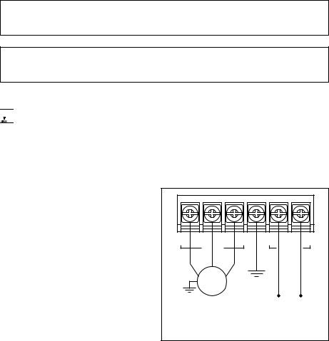
FIGURE 1 – QUICK-START CONNECTION DIAGRAM |
|||||
5, on page 14. |
|
|
|
|
|
|
|
1.2 AC LINE INPUT CONNECTION – Connect |
|
|
|
|
|
|
|
the single-phase AC line input to Terminal |
|
|
|
|
|
|
|
Block TB1 (Terminals “L1”, “L2”), as shown |
|
|
|
|
|
|
|
in Figure 1. See Section 6.1, on pages 14 |
TB1 |
U |
V |
W |
GND |
L1 |
L2 |
|
|||||||
and 15. |
|
|
MOTOR |
|
|
|
AC LINE |
|
|
|
|
|
|
||
Application Note – Do not connect this |
|
|
|
|
|
|
|
drive to a GFCI. If operation with a GFCI |
|
|
|
|
|
|
|
is required, contact our Sales Department. |
|
|
Motor |
|
Ground (Earth) |
|
|
|
|
|
|
|
see Section 6.2, |
|
|
Note: The drive is factory set for 208/230 |
|
|
3-Phase, 208/230 Volt |
on page 15. |
115* or 208/230 Volt |
||
Volt AC line input (Jumper J1 not installed). |
|
|
|
||||
|
|
AC Induction Motor |
Single-Phase AC Line Input |
||||
For 115 Volt AC line input, install Jumper |
|
|
|||||
|
|
see Section 6.3, on page 15. |
see Section 6.1, on pages 14 and 15. |
||||
J1 (supplied). See Section 7.1, on page 16. |
|
|
* For 115 VAC line, install Jumper J1 (supplied). |
||||
|
|
|
|||||
1.3AC LINE FUSING – It is recommended that a
fuse(s) or circuit breaker be installed in the AC line. Fuse each conductor that is not at ground potential. For the recommended fuse size, see Table 3, on page 9. Also see Section 6.1, on pages 14 and 15.
1.4GROUND CONNECTION – Connect the ground wire (earth) to Terminal Block TB1 (Terminal “GND”), as shown in Figure 1, above.
1.5MOTOR CONNECTION – Connect the motor to Terminal Block TB1 (Terminals “U”, “V”, “W”), as shown in Figure 1, on page 4. (Special reactors may be required for cable lengths over 100 ft. (30 m) – consult our Sales Department.). See Section 6.3, on page 15.
4

1.6JUMPER SETTINGS – All jumpers have been factory set for most applications, as shown in Figure 4, on page 12. Some applications require setting of the jumpers in order to set the drive for a specific
application. Jumper J2 must be set to match the horsepower of the motor being used. See Section 7, on pages 16 – 18.
1.760 Hz and 50 Hz MOTOR OPERATION – The drive is factory set for 60 Hz motor operation (Jumper J5 set to the “60Hz” position). For 50 Hz motor operation, set Jumper J5 to the “50Hz” position. See Section 7.4, on pages 17 and 18.
1.8PILOT LIGHT – After applying power to the drive and setting the On/Off AC Line Switch to the “ON” position, the panel mounted Pilot Light will illuminate.
1.9DIAGNOSTIC LEDs – After applying power to the drive and setting the On/Off AC Line Switch to the “ON” position, observe the PC board mounted LEDs for proper drive operation. See Section 10, on pages 20 & 21.
1.10TRIMPOT SETTINGS – All trimpots have been factory set for most applications, as shown in Figure 4, on page 12. Some applications require adjustment of the trimpots in order to setup the drive for a specific requirement. See Section 11, on pages 21 – 23.
2SAFETY WARNING
Definition of Safety Warning Symbols
Electrical Hazard Warning Symbol – Failure to observe this warning could result in electrical shock or electrocution.
Operational Hazard Warning Symbol – Failure to observe this warning could result in serious injury or death.
This product should be installed and serviced by a qualified technician, electrician, or electrical maintenance person familiar with its operation and the hazards involved. Proper installation,
which includes wiring, fusing or other current protection, and grounding can reduce the chance of electrical shocks, and/or fires, in this product or products used with this product, such as electric motors, switches, coils, solenoids, and/or relays. Do not use this drive in an explosion-proof application. Eye protection must be worn and insulated adjustment tools must be used when working with drive under power. This product is constructed of materials (plastics, metals, carbon, silicon, etc.) which may be a potential hazard. Proper shielding, grounding, and filtering of this product can reduce the emission of radio frequency interference (RFI) which may adversely affect sensitive electronic equipment. It is the responsibility of the equipment manufacturer and individual installer to supply this Safety Warning to the ultimate end user of this product. (SW 1/2006)
The drive contains electronic Start/Stop circuits which can be used to start and stop the drive. However, these circuits are never to be used as safety disconnects since they are not fail-safe. Use only the AC line for this purpose.
Be sure to follow all instructions carefully. Fire and/or electrocution can result due to improper use of this product.
5

This product complies with all CE directives pertinent at the time of manufacture. Contact our Sales Department for Declaration of Conformity. Installation of a CE approved RFI filter is required. See RFI
Filters & Chokes Selection Guide D-321 (Part No. A42027) for selection of filters to meet the Industrial or Residential Standard. Additional shielded cable and/or AC line cables may be required along with a signal isolator.
3INTRODUCTION
Thank you for purchasing the KBMA Adjustable Frequency Drive. KB Electronics, Inc. is committed to providing total customer satisfaction by producing quality products that are easy to install and operate. The KBMA is manufactured with surface mount components incorporating advanced circuitry and technology. The KBMA Series Adjustable Frequency Drives are variable speed controls housed in a NEMA-1 / IP-40 enclosure. They are designed to operate 208 – 230 Volt 50 & 60 Hz 3-phase AC induction motors from 1/8 HP thru 1 HP. The sine wave coded Pulse Width Modulated (PWM) output operates at a carrier frequency of 16 kHz which provides high motor efficiency and low noise. Adjustable Linear Acceleration and Deceleration make the drive suitable for soft-start applications. The Motor Horsepower Selection Jumper allows the drive to be used on a wide range of motor horsepower (1/8, 1/4, 1/2, 3/4, 1 HP) without recalibration or programming. Model KBMA-24DF contains a built-in AC line Class A RFI (EMI) filter which meets the CE Council Directive 89/336/EEC Industrial Requirement.
Its user-friendly design makes the KBMA easy to install and operate. Setting the drive to specific applications is accomplished with selectable jumpers and trimpots, which eliminates the computer-like programming required on other drives. However, for most applications no adjustments are necessary. For more advanced programming, PC based Drive-Link™ software is available.
Main features include adjustable RMS Current Limit and I2t Motor Overload Protection.1 In addition, Adjustable Slip Compensation with Static Auto-Tune and Boost provides high torque and excellent load regulation over a wide speed range. Power Start™ delivers over 200% motor torque to ensure startup of high frictional loads.
Electronic Inrush Current Limit (EICL™) eliminates harmful AC line inrush current. A Run/Fault Relay is provided, which can be used to turn on or off equipment or to signal a warning if the drive is put into the Stop Mode or a fault has occurred.
Standard front panel features include an On/Off AC Line Switch, a pilot light for power on, and a Main Speed Potentiometer. Other features include PC board mounted diagnostic LEDs (Power On (ON), Drive Status (ST) and Overload (OL)), Barrier Terminal Blocks to facilitate wiring (AC line, motor, ground (earth), and Run/Fault Relay Output Contacts), adjustable trimpots (MIN, MAX, ACCEL, DECEL, COMP, CL), customer selectable jumpers (AC Line Input Voltage Selection, Motor Horsepower, Automatic or Manual Start and Reset2, Motor Frequency, Frequency Multiplier, and a Run/Fault Output Relay).
Optional accessories include: Forward-Stop-Reverse Switch2, AC Line Filter, and Programming Kit.
Notes: 1. UL approved as an electronic overload protector for motors. 2. The optional Forward-Stop-Reverse Switch is required for Manual Start.
3.1STANDARD FEATURES
•Simple to Operate – Does not require programming. Uses trimpots and jumpers, which are factory set for most applications.
•Dual AC Line Input Voltage (115 or 208/230 Volt AC Operation) – Controls 208 – 230 Volt AC, 50 & 60 Hz, 3-phase motors from 115 or 208/230 Volt AC line. (Jumper J1 must be installed for 115 Volt AC line operation.)
6
•Motor Horsepower Selection Jumper – Allows the drive to be used on a wide range of motor horsepower (1/8, 1/4, 1/2, 3/4, 1 HP) without recalibration or programming.
•Diagnostic LEDs – PC board mounted LEDs for Power On (ON), Drive Status (ST), and Overload (OL).
•Run/Fault Relay Output Contacts – Can be used to turn on or off equipment or to signal a warning if the drive is put into the Stop Mode or a fault has occurred.
•Barrier Terminal Blocks – Facilitate wiring of AC line, motor, ground (earth) and Run/Fault Relay Output Contacts.
•On/Off AC Line Switch – Panel mounted. Used to turn the power on or off to the drive.
•Pilot Light – Panel mounted. Indicates that power is applied to the drive and the On/Off AC Line Switch is set to the “ON” position.
•Main Speed Potentiometer – Panel mounted. Provides adjustment of motor speed.
•Jumper Selection of Drive Output Frequency – Increases the motor speed up to two times the rated RPM.
•Compatible with GFCIs (with optional software).
3.2PERFORMANCE FEATURES
•Power Start™ – Provides more than 200% starting torque which ensures startup of high frictional loads.
•Slip Compensation with Static Auto-Tune and Boost – Provides excellent load regulation over a wide speed range.
•Speed Range – 60:1
3.3PROTECTION FEATURES
•Motor Overload (I2t) with RMS Current Limit – Provides motor overload protection which prevents motor burnout and eliminates nuisance trips.*
•Electronic Inrush Current Limit (EICL™) – Eliminates harmful inrush AC line current during startup.
•Short Circuit – Shuts down the drive if a short circuit occurs at the motor (phase-to-phase).
•Regeneration – Eliminates tripping due to bus overvoltage caused by rapid deceleration of high inertial loads.
•Undervoltage and Overvoltage – Shuts down the drive if the AC line input voltage goes above or below the operating range.
•MOV input transient suppression.
•Microcontroller self monitoring and auto-reboot.
*UL approved as an overload protector for motors.
3.4SELECTABLE JUMPERS (See Section 7, on pages 16 – 18.)
•AC Line Input Voltage Selection (115/230 Volts AC) (J1)
•Motor Horsepower (1/8, 1/4, 1/2, 3/4, 1 HP) (J2)
•Automatic or Manual Start and Reset (J3)
•Frequency Multiplier (1X, 2X) (J4)
•Motor Frequency (50/60 Hz) (J5)
•“Run” or “Fault” Output Relay Operation (J6)
7
3.5 TRIMPOT ADJUSTMENTS (See Section 11, on pages 21 – 23.)
• Minimum Speed (MIN)
• Maximum Speed (MAX)
• Acceleration (ACCEL)
• Deceleration (DECEL)
• Slip Compensation (COMP)
• Current Limit (CL)
TABLE 1 – OPTIONAL ACCESSORIES
Description |
Part No. |
|
|
|
|
Forward-Stop-Reverse Switch: Provides motor reversing, stop, and manual start functions. |
9519 |
|
|
|
|
KBRF-300: Panel mount. AC line Class B RFI (EMI) filter which meets the CE Council Directive 89/336/EEC Residential |
9484 |
|
Requirement. Installs externally to the drive. |
||
|
||
|
|
|
Programming Kit: Includes DownLoad Module™ (DLM) handheld programming device which uploads and downloads |
|
|
drive programs, PC to DLM serial communication cable, PC to DLM serial and USB communication cables, DLM to drive |
9582 |
|
communication cable, and PC Windows® based Drive-Link™ communication software. Available for OEM applications |
||
|
||
only – contact our Sales Department. |
|
|
|
|
8
 Loading...