


Installation and Operation Manual
KBMM™ |
L1 |
|
|
|
A+ |
F- |
Surface Mount Technology |
DECEL |
|
L2 |
|
|
|
Solid State SCR |
|
|
|
|
||
|
|
F+ |
|
|
|
|
DC Motor Speed Controls |
|
|
|
B |
J2 |
|
|
|
|
|
|
||
|
|
T |
|
|
CL |
|
for Use with 1/100 – 3 HP, 90 and 180 Volt |
|
|
|
|
|
|
ACCEL |
|
|
|
|
|
|
Permanent Magnet and Shunt Wound DC Motors* |
|
|
J1 |
|
PWR |
A- |
|
|
CONN1 |
P2 |
|
ON |
|
|
EN |
|
|
|
||
|
I1 |
|
|
|
||
AC Line Input: 115 and 208/230 Volts, 50/60 Hz |
|
P3 |
P1 |
|
|
|
This Manual Covers Models KBMM-125, 225, 225D |
|
|
|
|
I2 |
|
MAX |
|
MIN |
|
|
CL IR |
|
|
|
|
|
PATENTED |
|
|
Ultra Fast Current Limit Circuit Prevents
Demagnetization in Permanent Magnet Motors
! |
See Safety Warning on page 6. |
|
|
|
|
|
|
|
A Plug-In Horsepower Resistor® and AC Line |
|
|
|
|
|
|
|
|
and Armature Fuses, supplied separately, |
|
|
|
|
|
|
|
|
must be installed for this product to operate. |
|
|
|
|
|
|
* |
|
||
|
|
|
|
|
|
|||
|
||||||||
|
|
|
|
|
|
|
|
|
*See page 6 |
*Auxiliary Heat Sink (Part No. 9861) is required |
|||||||
to achieve maximum rating of control. See |
||||||||
|
|
for CE |
||||||
|
|
Electrical Ratings, Table 1, on page 9. |
||||||
Information |
||||||||
|
||||||||
The information contained in this manual is intended to be accurate. However, the manufacturer retains the right to make changes in design which may not be included herein.
|
|
|
|
Manufactured |
A COMPLETE LINE OF MOTOR DRIVES |
© 2004 KB Electronics, |
Inc. |
in the USA |
|
(See back cover) |
|
|
TABLE OF CONTENTS |
|
Section |
Page |
|
1 |
Simplified Installation Instructions . . . . . . . . . . . . . . . . . . . . . . . . . . . . . . . . . . . . . . . . . . . . . . . . . . . . . . . . . . |
. . . 4 |
2 |
Safety Warning . . . . . . . . . . . . . . . . . . . . . . . . . . . . . . . . . . . . . . . . . . . . . . . . . . . . . . . . . . . . . . . . . . . . . . . . |
. . . 6 |
3 |
Introduction . . . . . . . . . . . . . . . . . . . . . . . . . . . . . . . . . . . . . . . . . . . . . . . . . . . . . . . . . . . . . . . . . . . . . . . . . . . |
. . . 7 |
4 |
Application Information . . . . . . . . . . . . . . . . . . . . . . . . . . . . . . . . . . . . . . . . . . . . . . . . . . . . . . . . . . . . . . . . . . |
. . 11 |
5 |
Mounting Instructions . . . . . . . . . . . . . . . . . . . . . . . . . . . . . . . . . . . . . . . . . . . . . . . . . . . . . . . . . . . . . . . . . . . |
. . 12 |
6 |
Wiring Instructions . . . . . . . . . . . . . . . . . . . . . . . . . . . . . . . . . . . . . . . . . . . . . . . . . . . . . . . . . . . . . . . . . . . . . |
. . 13 |
7 |
Setting Selectable Jumpers . . . . . . . . . . . . . . . . . . . . . . . . . . . . . . . . . . . . . . . . . . . . . . . . . . . . . . . . . . . . . . |
. . 19 |
8 |
AC Line and Armature Fusing . . . . . . . . . . . . . . . . . . . . . . . . . . . . . . . . . . . . . . . . . . . . . . . . . . . . . . . . . . . . . |
. . 20 |
9 |
Plug-In Horsepower Resistor® . . . . . . . . . . . . . . . . . . . . . . . . . . . . . . . . . . . . . . . . . . . . . . . . . . . . . . . . . . . . |
. . 21 |
10 |
Recommended High Voltage Dielectric Withstand Testing (Hi-Pot Testing) . . . . . . . . . . . . . . . . . . . . . . . . . . . |
. . 22 |
11 |
Trimpot Adjustments . . . . . . . . . . . . . . . . . . . . . . . . . . . . . . . . . . . . . . . . . . . . . . . . . . . . . . . . . . . . . . . . . . . . |
. . 24 |
12 |
Diagnostic LEDs . . . . . . . . . . . . . . . . . . . . . . . . . . . . . . . . . . . . . . . . . . . . . . . . . . . . . . . . . . . . . . . . . . . . . . . |
. . 28 |
13 |
Switching Circuits . . . . . . . . . . . . . . . . . . . . . . . . . . . . . . . . . . . . . . . . . . . . . . . . . . . . . . . . . . . . . . . . . . . . . . |
. . 28 |
14 |
Optional Accessories . . . . . . . . . . . . . . . . . . . . . . . . . . . . . . . . . . . . . . . . . . . . . . . . . . . . . . . . . . . . . . . . . . . |
. . 30 |
Limited Warranty . . . . . . . . . . . . . . . . . . . . . . . . . . . . . . . . . . . . . . . . . . . . . . . . . . . . . . . . . . . . . . . . . . . . . . . . . . |
. . 32 |
|
Tables
1 Electrical Ratings . . . . . . . . . . . . . . . . . . . . . . . . . . . . . . . . . . . . . . . . . . . . . . . . . . . . . . . . . . . . . . . . . . . . . . . . . 9 2 General Performance Specifications . . . . . . . . . . . . . . . . . . . . . . . . . . . . . . . . . . . . . . . . . . . . . . . . . . . . . . . . . . . 9 3 Minimum Supply Wire Size Requirements . . . . . . . . . . . . . . . . . . . . . . . . . . . . . . . . . . . . . . . . . . . . . . . . . . . . . . 13 4 Field Connection (Shunt Wound Motors Only) . . . . . . . . . . . . . . . . . . . . . . . . . . . . . . . . . . . . . . . . . . . . . . . . . . . 14 5 AC Line and Armature Fuse Selection . . . . . . . . . . . . . . . . . . . . . . . . . . . . . . . . . . . . . . . . . . . . . . . . . . . . . . . . . 21 6 Plug-In Horsepower Resistor® Selection . . . . . . . . . . . . . . . . . . . . . . . . . . . . . . . . . . . . . . . . . . . . . . . . . . . . . . 22 7 RFI Filter Selection . . . . . . . . . . . . . . . . . . . . . . . . . . . . . . . . . . . . . . . . . . . . . . . . . . . . . . . . . . . . . . . . . . . . . . . 31
2
|
TABLE OF CONTENTS (Continued) |
|
Figures |
Page |
|
1 |
Control Layout and General Connection Diagram . . . . . . . . . . . . . . . . . . . . . . . . . . . . . . . . . . . . . . . . . . . . . . |
. . 10 |
2 |
Mechanical Specifications . . . . . . . . . . . . . . . . . . . . . . . . . . . . . . . . . . . . . . . . . . . . . . . . . . . . . . . . . . . . . . . . |
. . 11 |
3 |
Remote Main Speed Potentiometer Connection . . . . . . . . . . . . . . . . . . . . . . . . . . . . . . . . . . . . . . . . . . . . . . . |
. . 15 |
4 |
Voltage Following Connection . . . . . . . . . . . . . . . . . . . . . . . . . . . . . . . . . . . . . . . . . . . . . . . . . . . . . . . . . . . . . |
. . 15 |
5 |
Enable Switch or Contact Wired to the Enable Connector . . . . . . . . . . . . . . . . . . . . . . . . . . . . . . . . . . . . . . . |
. . 16 |
6 |
Enable Switch or Contact Wired to the Main Speed Potentiometer . . . . . . . . . . . . . . . . . . . . . . . . . . . . . . . . |
. . 17 |
7 |
Inhibit Switch or Contact Wired to the Inhibit Terminals . . . . . . . . . . . . . . . . . . . . . . . . . . . . . . . . . . . . . . . . . . |
. . 17 |
8 |
DC Tach-Generator Connection (7 Volts per 1000 RPM) . . . . . . . . . . . . . . . . . . . . . . . . . . . . . . . . . . . . . . . . |
. . 18 |
9 |
DC Tach-Generator Connection (50 Volts per 1000 RPM) . . . . . . . . . . . . . . . . . . . . . . . . . . . . . . . . . . . . . . . |
. . 18 |
10 |
Other DC Tach-Generator Connection (with Addition of RT) . . . . . . . . . . . . . . . . . . . . . . . . . . . . . . . . . . . . . . |
. . 19 |
11 |
AC Line Input Voltage Selection (Jumper J1 (Model KBMM-225D Only)) . . . . . . . . . . . . . . . . . . . . . . . . . . . . |
. . 20 |
12 |
Motor Voltage and DC Tach-Generator Selection (Jumper J2) . . . . . . . . . . . . . . . . . . . . . . . . . . . . . . . . . . . . |
. . 20 |
13 |
Hi-Pot Test Setup . . . . . . . . . . . . . . . . . . . . . . . . . . . . . . . . . . . . . . . . . . . . . . . . . . . . . . . . . . . . . . . . . . . . . . |
. . 23 |
14 |
Acceleration Trimpot (ACCEL) Range . . . . . . . . . . . . . . . . . . . . . . . . . . . . . . . . . . . . . . . . . . . . . . . . . . . . . . . |
. . 24 |
15 |
Deceleration Trimpot (DECEL) Range . . . . . . . . . . . . . . . . . . . . . . . . . . . . . . . . . . . . . . . . . . . . . . . . . . . . . . . |
. . 25 |
16 |
Minimum Speed Trimpot (MIN) Range . . . . . . . . . . . . . . . . . . . . . . . . . . . . . . . . . . . . . . . . . . . . . . . . . . . . . . . |
. . 25 |
17 |
Maximum Speed Trimpot (MAX) Range . . . . . . . . . . . . . . . . . . . . . . . . . . . . . . . . . . . . . . . . . . . . . . . . . . . . . . |
. . 25 |
18 |
Current Limit Trimpot (CL) Range . . . . . . . . . . . . . . . . . . . . . . . . . . . . . . . . . . . . . . . . . . . . . . . . . . . . . . . . . . |
. . 26 |
19 |
IR Compensation Trimpot (IR) Range . . . . . . . . . . . . . . . . . . . . . . . . . . . . . . . . . . . . . . . . . . . . . . . . . . . . . . . |
. . 27 |
20 |
Typical Dynamic Brake Circuit Connection . . . . . . . . . . . . . . . . . . . . . . . . . . . . . . . . . . . . . . . . . . . . . . . . . . . |
. . 29 |
Items Included in this package – KBMM™ Speed Control, KBMM™ Installation and Operation Manual, Hardware Bag (contains Main Speed Potentiometer with insulator and mounting hardware, (9) – 0.25” female crimp-on terminals, (4) – 0.11” female crimp-on terminals, and an Enable harness), CE Approved Product Information Card, and Warranty Registration Card.
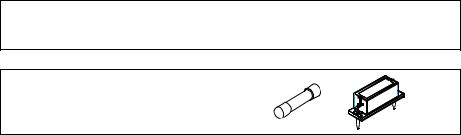
Items required to operate this control – Plug-In Horsepower Resistor®, AC Line Fuse and Armature Fuse. Supplied
through your distributor. See Sections 8 and 9, on pages 20 - 22. |
3 |
1 SIMPLIFIED INSTALLATION INSTRUCTIONS
IMPORTANT – Read these simplified installation instructions before proceeding. These instructions are to be used as a reference only and are not intended to replace the detailed instructions provided herein. You must read the Safety Warning, on page 6, before proceeding.
Note: A Plug-In Horsepower Resistor® and AC Line and |
|
|
Armature Fuses, supplied separately, must be installed in |
|
|
order for this product to operate. See Section 9, on page 21. |
Fuse |
Plug-In Horsepower |
|
|
Resistor® |
1.1AC Line Connection – Wire the AC line to Terminals “L1” (Line Fuse) and “L2”, as shown in Figure 1, on page 10 and as described in Section 6.1, on page 13.
Model KBMM-125 is rated for 115 Volt AC line input only. Model KBMM-225 is rated for 230 Volt AC line input only. Model KBMM-225D is rated for 115 Volt AC line input (Jumper J1 in the “115” position) and 230 Volt AC line input (Jumper J1 in the “230” position). See Section 7.1, on page 19.
Notes: 1. The rated AC line voltage (115, 208/230) of the control must match the actual AC line input voltage. 2. If one of the AC line inputs is a neutral (N), wire it to Terminal “L2”.
1.2Ground Connection – Connect the ground wire (earth) to the control chassis.
1.3Motor Connection – Connect the motor to Terminals “A+” (Armature Fuse) and “A-”, as shown in Figure 1, on page 10, and as described in Section 6.3, on page 14.
1.4Jumper Settings – Jumper J1 (on Model KBMM-225D only) and Jumper J2 (all models) have been factory set for most applications, as shown in Figure 1, on page 10, and as described in Section 7, on page 19.
4
1.5AC line Fusing – It is required that an AC line fuse (supplied separately) be installed in the AC Line Fuse Holder, as shown in Figure 1, on page 10. Select the correct AC Line Fuse, as described in Section 8, on pages 20 and 21. Fuse each conductor that is not at ground potential.
1.6Armature Fusing – It is required that an Armature Fuse (supplied separately) be installed in the Armature Fuse Holder, as shown in Figure 1, on page 10. Select the correct Armature Fuse as described in Section 8, on pages 20 and 21.
1.7Plug-In Horsepower Resistor® – Install the correct Plug-In Horsepower Resistor® according to armature voltage and motor horsepower, as shown in Figure 1, on page 10. Select the correct Plug-In Horsepower Resistor®, as described in Section 9, on pages 21 and 22.
1.8Trimpot Settings – All trimpots have been factory set for most applications, as shown in Figure 1, on page 10. The trimpots may be readjusted, as described in Section 11, on page 24.
1.9Diagnostic LEDs – After power has been applied to the control, observe the LEDs to verify proper control operation, as described in Section 12, on page 28.
1.10Auxiliary Heat Sink (Part No. 9861) – Extends the horsepower rating of the control to 1.5 HP for controls with 90 Volt DC output and 3 HP for controls with 180 Volt DC output.
5

2SAFETY WARNING – Please read carefully. Definition of Safety Warning Symbols:
Electrical Hazard Warning Symbol – Failure to observe this warning could result in electrical shock or electrocution.
Operational Hazard Warning Symbol – Failure to observe this warning could result in serious injury ! or death.
This product should be installed and serviced by a qualified technician, electrician, or electrical main-
 ! tenance person familiar with its operation and the hazards involved. Proper installation, which includes wiring, mounting in proper enclosure, fusing or other over current protection, and grounding can reduce the chance of electrical shocks, fires, or explosion in this product or products used with this product, such as electric motors, switches, coils, solenoids, and/or relays. Eye protection must be worn and insulated adjustment tools must be used when working with control under power. This product is constructed of materials (plastics, metals, carbon, silicon, etc.) which may be a potential hazard. Proper shielding, grounding, and filtering of this product can reduce the emission of radio frequency interference (RFI) which may adversely affect sensitive electronic equipment. It is the responsibility of the equipment manufacturer and individual installer to supply this Safety Warning to the ultimate end user of this product. (SW effective 11/1992). Be sure to follow all instructions carefully. Fire and/or electrocution can result due to improper use of this product.
This product complies with all CE directives pertinent at the time of manufacture. Contact the Sales Department for Declaration of Conformity. Installation of a CE approved RFI filter is required (see Section 14.12, on page 30). Additional shielded cable and/or AC line cables may be required along with a sig-
nal isolator (SI-6 (Part No. 9444)).
6
3INTRODUCTION
Thank you for purchasing the KBMM™ “Standard of the Industry” full-wave variable speed DC motor control, now with SMT construction. The control offers the user the ultimate in reliability and performance at an affordable price. The controls contain a unique patented super-fast Direct-Fed™ current limit circuit that protects the SCR power bridge against direct shorts1. The reliability of the control is further enhanced with the use of high-surge, 25 Amp SCRs, and AC line and armature fusing2, 3. The control is designed with KB’s exclusive Plug-In Horsepower Resistor® 3, which eliminates the need for recalibrating IR Comp and Current Limit when the control is used on various horsepower motors. In addition, the rating of the control can be extended to 1.5 HP for controls with 90 Volt DC output and 3 HP for controls with 180 Volt DC output, by the use of KB’s Auxiliary Heat Sink4. Models KBMM-225 and KBMM-225D also allow operation of 90 Volt DC motors when used on 208/230 Volt AC line input 5.
The versatility of the control is confirmed by its extensive list of standard features, such as: selectable armature and tach feedback and adjustment trimpots for minimum speed, maximum speed, current limit, IR compensation, and linear acceleration and deceleration. The control includes Auto-Inhibit®, which eliminates surging during rapid AC line switching; pulse transformer triggering, which provides cogless operation at low speed; and superior noise rejection circuitry, which eliminates false starts and blown SCRs. Enable (normally closed) and Inhibit (normally open) functions provide electronic switching of control output.
The output voltage of the control is a linear function of the Main Speed Potentiometer rotation. In addition, the control can be used in a voltage following mode by supplying an isolated analog input signal to Terminals “P2” (+)
and “P1” (-) 6. The control is compact in size (only 4.30” X 3.64” X 1.25”) and easily replaces all competitive speed controls. The control is supplied with a 5 k Ω Main Speed Potentiometer and QD terminals. All models are UL
Listed (USA and Canada) and CE Approved.
Notes: 1. Short circuit protected at motor only. 2. KB Limited Warranty applies. See page 32. 3. Fuses and Plug-In Horsepower Resistor® supplied separately. See Sections 8 and 9, on pages 20 - 22. 4. Part No. 9861. See Section 14.1, on page 30. 5. Step-Down operation. 6. If an isolated signal input is not available, or if using a 4 - 20 mA DC signal input, install the optional plug-on SI-6 Signal Isolator (Part No. 9444).
7
3.1Standard Features
1Plug-In Horsepower Resistor® – Eliminates the need to calibrate the control for IR Compensation and Current Limit when used on various horsepower motors.
2Auto-Inhibit® – Allows the control to be rapidly switched “on” and “off” using the AC line.
3Inhibit and Enable – Allows the control to be turned “on” and “off” using electronic switching.
4Trimpots – Minimum Speed (MIN), Maximum Speed (MAX), IR Compensation (IR), Current Limit (CL), Acceleration (ACCEL), and Deceleration (DECEL).
5Jumpers – AC Line Input Voltage Selection (J1 (Model KBMM-225D only)), Motor Voltage and DC Tach-Generator Selection (J2).
6Protection Features – MOV transient protection. Short Circuit protected (at motor only).
7Diagnostic LEDs – Power On (PWR ON) and Current Limit (CL).
8Model KBMM-125 operates on 115 Volt AC line input with 90 Volt DC motors.
9Model KBMM-225 operates on 230 Volt AC line input with 180 Volt DC motors or 90 Volt DC motors (step-down). - Jumper Selectable.
10Model KBMM-225D can operate on 115 Volt AC line input with 90 Volt DC motors and 230 Volt AC line input with 180 Volt DC motors or 90 Volt DC motors (step-down). - Jumper selectable.
11Armature or DC Tach-Generator feedback.
12Built-in AC line and armature fusing.
13Main Speed Potentiometer (5 kΩ).
14SMT construction.
8
TABLE 1 – ELECTRICAL RATINGS
|
|
|
AC Line |
|
Motor |
Maximum Rating without Auxiliary Heat Sink |
Maximum Rating with Auxiliary Heat Sink |
Field |
|||||
|
Part |
|
Voltage |
|
AC Line |
DC Load |
|
AC Line |
DC Load |
|
|||
Model |
|
|
Voltage |
Horsepower |
Horsepower |
Voltage |
|||||||
No. |
|
(±15%, 50/60Hz) |
Current |
Current |
Current |
Current |
|||||||
|
|
(Volts DC) |
(HP (kw)) |
(HP (kw)) |
(Volts DC) |
||||||||
|
|
|
(Volts AC) |
|
(RMS Amps) |
(Avg. Amps) |
(RMS Amps) |
(Avg. Amps) |
|||||
|
|
|
|
|
|
|
|
||||||
KBMM-125 |
9449 |
|
115 |
|
0 - 90 |
12.0 |
8.0 |
.75 (.6) |
24.0 |
16.0 |
1.5 (1.1) |
50, 100 |
|
|
|
|
|
|
|
|
|
|
|
|
|
|
|
KBMM-225 |
9450 |
|
230 |
|
0 - 180 |
12.0 |
8.0 |
1.5 (1.1) |
24.0 |
16.0 |
3 (2.3) |
100, 200 |
|
|
|
|
|
|
|
|
|
|
|
|
|||
|
|
0 - 90* |
12.0 |
8.0 |
.75 (.6) |
24.0 |
16.0 |
1.5 (1.1) |
100 |
||||
|
|
|
|
|
|||||||||
|
|
|
|
|
|
|
|
|
|
|
|
|
|
|
|
|
115 |
|
0 - 90 |
12.0 |
8.0 |
.75 (.6) |
24.0 |
16.0 |
1.5 (1.1) |
50, 100 |
|
|
|
|
|
|
|
|
|
|
|
|
|
|
|
KBMM-225D |
9451 |
|
230 |
|
0 - 180 |
12.0 |
8.0 |
1.5 (1.1) |
24.0 |
16.0 |
3 (2.3) |
100, 200 |
|
|
|
|
|
|
|
|
|
|
|
|
|
|
|
|
|
|
|
0 - 90* |
12.0 |
8.0 |
.75 (.6) |
24.0 |
16.0 |
1.5 (1.1) |
100 |
||
|
|
|
|
|
|||||||||
|
|
|
|
|
|
|
|
|
|
|
|
|
|
* Step-down operation. |
|
|
|
|
|
|
|
|
|
|
|
||
|
|
|
|
TABLE 2 – GENERAL PERFORMANCE SPECIFICATIONS |
|
|
|||||||
|
|
|
|
|
|
|
|
|
|
||||
Description |
|
|
|
|
|
|
|
Specification |
Factory Setting |
||||
Speed Range (Ratio) |
|
|
|
|
|
|
|
50:1 |
— |
|
|||
|
|
|
|
|
|
||||||||
Armature Feedback Load Regulation (0 - Full Load, 50:1 Speed Range) (% Base Speed) |
|
|
1 |
— |
|
||||||||
|
|
|
|
|
|
||||||||
Tach-Generator Feedback Load Regulation (0 - Full Load, 50:1 Speed Range) (% Set Speed) |
|
|
1 |
— |
|
||||||||
|
|
|
|
|
|
|
|||||||
Line Voltage Regulation (at Full Load, ± 10% Line Variation) (% Speed) |
|
|
|
0.5 |
— |
|
|||||||
|
|
|
|
|
|
|
|
||||||
Control Linearity (% Output Voltage vs Signal Input Voltage) |
|
|
|
|
2 |
— |
|
||||||
|
|
|
|
|
|
|
|
|
|||||
Acceleration (ACCEL) Trimpot Range (Seconds) |
|
|
|
|
|
0.2 – 10 |
2 |
|
|||||
|
|
|
|
|
|
|
|
|
|||||
Deceleration (DECEL) Trimpot Range (Seconds) |
|
|
|
|
|
0.2 – 10 |
2 |
|
|||||
|
|
|
|
|
|
|
|||||||
Maximum Speed (MAX) Trimpot Range (% Base Speed) |
|
|
|
|
50 – 110 |
100 |
|||||||
|
|
|
|
|
|
|
|
||||||
Minimum Speed (MIN) Trimpot Range (% Base Speed) |
|
|
|
|
0 – 30 |
0 |
|
||||||
|
|
|
|
|
|
|
|
||||||
Current Limit (CL) Trimpot Range (% Full Load) |
|
|
|
|
|
0 – 200 |
150 |
||||||
|
|
|
|
||||||||||
IR Compensation (IR) Trimpot Range (at Specified Full Load @ 90, 180 Volts DC Output) (Volts DC) |
|
0 – 24, 48 |
3, 6 |
||||||||||
|
|
|
|
|
|
|
|
|
|
|
|
|
|
Notes: 1. Step-down operation: motor may have reduced brush life. Consult motor manufacturer. 2. Performance is for SCR rated permanent magnet motors only. Lower performance can be expected with other motor types. Factory setting is for 3% load regulation. To obtain superior regulation, see Section 11.6, on page 27.
9

FIGURE 1 – CONTROL LAYOUT & GENERAL CONNECTION DIAGRAM (Model KBMM-225D Shown)
(Note: Control is set for 208 /230 VAC line input, 0 - 180 VDC output with armature feedback)
|
|
|
|
|
|
Red |
Plug-In |
|
|
|
|
|
|
|
Horsepower Resistor® |
||
|
|
|
|
|
|
|
||
|
Blue |
|
|
|
|
|
Supplied Separately |
|
|
L1 |
|
|
A+ |
|
F- |
|
|
|
|
|
|
|
|
|
||
|
DECEL |
|
|
L2 |
|
|
|
|
|
AC Line Fuse |
|
|
|
|
|
Armature Fuse |
|
|
Supplied Separately |
|
|
F+ |
|
|
Supplied Separately |
|
|
|
|
|
B |
J2 |
|
|
|
|
|
|
|
|
|
|
|
|
|
|
|
|
T |
CL |
|
|
|
|
|
|
|
|
|
|
|
|
|
ACCEL |
|
|
|
|
|
For Plug-In Horsepower |
|
|
|
|
|
|
|
Resistor®, Line Fuse, |
||
|
Enable Switch |
|
|
J1 |
|
|
||
|
|
|
|
|
and Armature Fuse |
|||
|
(Close to Run) |
|
|
PWR |
|
A- |
||
|
|
|
|
Selection See Sections |
||||
|
(Open to Stop) |
|
|
ON |
|
|
||
|
CONN1 |
P2 |
|
|
8 and 9, on pages 20-22. |
|||
|
EN |
|
|
|
||||
|
|
I1 |
|
|
|
|
||
|
|
|
|
|
|
|
|
|
|
|
P3 |
|
P1 |
|
|
|
|
|
|
|
|
I2 |
|
|
|
|
|
MAX |
|
|
MIN |
CL |
IR |
|
|
|
High |
|
|
|
+ |
+ |
+ |
|
|
|
|
|
|
|
|
|
|
|
Wiper |
|
|
|
|
M |
G |
7V |
|
Low |
|
|
|
|
1000 |
||
|
|
|
|
|
|
|
||
|
|
|
|
|
- |
- |
- |
|
AC Line |
Main Speed Potentiometer |
|
|
Inhibit Switch |
Motor Field |
Motor Armature |
DC Tach-Generator |
|
Input |
(Front View) |
|
|
(Open to Run) |
(Shunt Motors Only) |
|
(Set J2 to "T" Position) |
|
|
|
|
|
(Close to Stop) |
|
|
|
|
10
 Loading...