


 “The Right Control for Your Application.”
KB Electronics, Inc. |
12095 NW 39 Street, Coral Springs, FL 33065-2516
Telephone: 954-346-4900; Fax: 954-346-3377
www.kbelectronics.com
KBRG-240D (Part No. 8800), KBRG-225D (Part No. 8802), KBRG-255 (Part No. 8821)
Installation and Operation Manual Supplemental Information
This supplement is for Models KBRG-240D, KBRG-225D, and KBRG-255 Installation and Operation Manuals (Part Nos. A40260 and A40287) until the new manuals are available. The manuals must be read and understood before operating these controls. For further assistance, contact our Sales Department at 954-346-4900 or Toll Free at 800-221-6570 (outside Florida).
These Controls have been Converted to Surface Mount Technology (SMT)
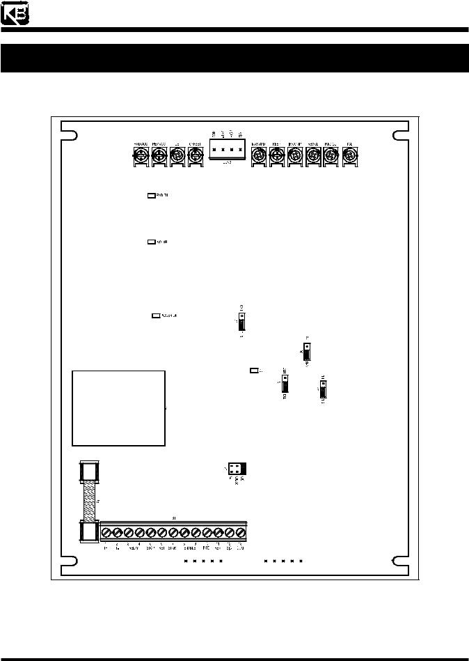
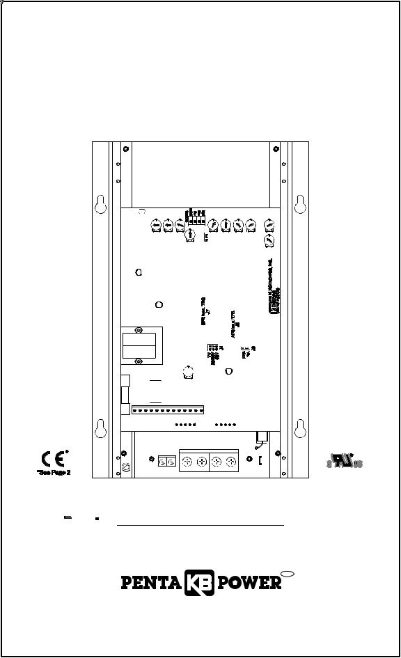
The OFFSET and TCL trimpots have been moved to be aligned with the other trimpots. The General Performance Specifications, Electrical Ratings, Mechanical Specifications, and Connection Diagrams have not changed. The Parts Lists and Schematics in the manuals no longer apply to these controls and should not be used. See Figure 1, below, for Models KBRG-225D and KBRG-240D Logic Board’s Trimpot and Jumper location changes. See Figure 2, on page 2, for Model KBRG-255 Logic Board’s Trimpot and Jumper location changes.
Figure 1 |
|
Models KBRG-225D and KBRG-240D Logic Board Layout |
|
(A42143) – Rev. A00 – 2/27/2007– Z4431A00 |
Page 1 of 2 |


 “The Right Control for Your Application.”
KB Electronics, Inc. |
12095 NW 39 Street, Coral Springs, FL 33065-2516
Telephone: 954-346-4900; Fax: 954-346-3377
www.kbelectronics.com
KBRG-240D (Part No. 8800), KBRG-225D (Part No. 8802), KBRG-255 (Part No. 8821)
Installation and Operation Manual Supplemental Information
|
Figure 2 |
|
Model KBRG-255 Logic Board Layout |
(A42143) – Rev. A00 – 2/27/2007– Z4431A00 |
Page 2 of 2 |
INSTALLATION AND OPERATING INSTRUCTIONS
REGENERATIVE DRIVE
MODEL KBRG-255 (5HP)
KB Part No. 8821
FULL WAVE • 4 QUADRANT
FWD |
FWD REV |
MAX |
IR |
REV |
FWD |
EN |
ACCEL ACCEL DB |
SPD |
RESP COMP |
CL |
CL |
|
S/LT |
|
|
|
|
|
NLT |
|
|
|
TCL |
|
OFFSET J8 |
|
|
|
|
REV |
|
|
|
|
|
EN |
|
|
|
|
|
|
PWR |
|
|
|
|
|
ON |
|
|
|
|
CL
 R33
R33
F1
TB1
1 2 3 4 5 6 7 8 9 10 11 12 13
(EARTH) |
|
|
|
|
|
TB1 |
|
|
TB2 J1 |
|
F+ F- |
|
|
|
GND |
L1 |
L2 |
M1 |
M2 |
|

 See Safety Warning on Page 1
The information contained in this manual is intended to be accurate. However, the manufacturer retains the right to make changes in design which may not be included herein.
™
A COMPLETE LINE OF MOTOR DRIVES
© 1999 KB Electronics, Inc.
TABLE OF CONTENTS
Section |
Page |
i. Simplified Setup and Operating Instructions . . . . . . . . . . . . . . . . . . . . . . . . . . . . . . . . . . . 1 ii. Safety Warning . . . . . . . . . . . . . . . . . . . . . . . . . . . . . . . . . . . . . . . . . . . . . . . . . . . . . . . . . 1 I. General Information . . . . . . . . . . . . . . . . . . . . . . . . . . . . . . . . . . . . . . . . . . . . . . . . . . . . . 2 II. Setting Mode of Drive (Speed or Torque Control) . . . . . . . . . . . . . . . . . . . . . . . . . . . . . . . 4 III. Setting Selectable Jumpers . . . . . . . . . . . . . . . . . . . . . . . . . . . . . . . . . . . . . . . . . . . . . . . 5 IV. Mounting . . . . . . . . . . . . . . . . . . . . . . . . . . . . . . . . . . . . . . . . . . . . . . . . . . . . . . . . . . . . . . 6 V. Wiring . . . . . . . . . . . . . . . . . . . . . . . . . . . . . . . . . . . . . . . . . . . . . . . . . . . . . . . . . . . . . . . . 6 VI. Fusing . . . . . . . . . . . . . . . . . . . . . . . . . . . . . . . . . . . . . . . . . . . . . . . . . . . . . . . . . . . . . . . 10 VII. Operation . . . . . . . . . . . . . . . . . . . . . . . . . . . . . . . . . . . . . . . . . . . . . . . . . . . . . . . . . . . . 10 VIII. Trimpot Adjustments . . . . . . . . . . . . . . . . . . . . . . . . . . . . . . . . . . . . . . . . . . . . . . . . . . . . 11 IX. Function Indicator Lamps . . . . . . . . . . . . . . . . . . . . . . . . . . . . . . . . . . . . . . . . . . . . . . . . 13 X. Limited Warranty . . . . . . . . . . . . . . . . . . . . . . . . . . . . . . . . . . . . . . . . . . . . . . . . . . . . . . . 20
|
|
TABLES |
1. |
Electrical Ratings . . . . . . . . . . . . . . . |
. . . . . . . . . . . . . . . . . . . . . . . . . . . . . . . . . . . . . . . . 2 |
2. |
General Performance Specifications . |
. . . . . . . . . . . . . . . . . . . . . . . . . . . . . . . . . . . . . . . . 2 |
3. |
Summary of Control Operation . . . . . |
. . . . . . . . . . . . . . . . . . . . . . . . . . . . . . . . . . . . . . . . 4 |
4. |
Terminal Block Wiring Information . . |
. . . . . . . . . . . . . . . . . . . . . . . . . . . . . . . . . . . . . . . . 7 |
5. |
Field Connections . . . . . . . . . . . . . . . |
. . . . . . . . . . . . . . . . . . . . . . . . . . . . . . . . . . . . . . . . 7 |
6. |
Control State vs Relay Contact State |
. . . . . . . . . . . . . . . . . . . . . . . . . . . . . . . . . . . . . . . 10 |
7. |
Current Limit Timer Settings . . . . . . . |
. . . . . . . . . . . . . . . . . . . . . . . . . . . . . . . . . . . . . . . 13 |
8. |
Parts List (Power Board) . . . . . . . . . . |
. . . . . . . . . . . . . . . . . . . . . . . . . . . . . . . . . . . . . . . 13 |
9. |
Parts List (Logic Board) . . . . . . . . . . |
. . . . . . . . . . . . . . . . . . . . . . . . . . . . . . . . . . . . 15, 16 |
|
|
FIGURES |
1. Control Layout . . . . . . . . . . . . . . . . . . . . . . . . . . . . . . . . . . . . . . . . . . . . . . . . . . . . . . . . . 3
2A. Linear Torque Curve . . . . . . . . . . . . . . . . . . . . . . . . . . . . . . . . . . . . . . . . . . . . . . . . . . . . . 5
2B. Non-Linear Torque Curve . . . . . . . . . . . . . . . . . . . . . . . . . . . . . . . . . . . . . . . . . . . . . . . . . 5
3. AC Line and Armature Connection . . . . . . . . . . . . . . . . . . . . . . . . . . . . . . . . . . . . . . . . . . 7
4A. Full Voltage Field . . . . . . . . . . . . . . . . . . . . . . . . . . . . . . . . . . . . . . . . . . . . . . . . . . . . . . . 7
4B. Half Voltage Field . . . . . . . . . . . . . . . . . . . . . . . . . . . . . . . . . . . . . . . . . . . . . . . . . . . . . . . 7
5. Mechanical Specifications . . . . . . . . . . . . . . . . . . . . . . . . . . . . . . . . . . . . . . . . . . . . . . . . . 8
6. Main Speed Potentiometer Connections . . . . . . . . . . . . . . . . . . . . . . . . . . . . . . . . . . . . . . 9
7A. Voltage Following . . . . . . . . . . . . . . . . . . . . . . . . . . . . . . . . . . . . . . . . . . . . . . . . . . . . . . . 9
7B. Enable . . . . . . . . . . . . . . . . . . . . . . . . . . . . . . . . . . . . . . . . . . . . . . . . . . . . . . . . . . . . . . 10
7C. Start/Stop Circuit . . . . . . . . . . . . . . . . . . . . . . . . . . . . . . . . . . . . . . . . . . . . . . . . . . . . . . . 10
7D. Alarm Contacts . . . . . . . . . . . . . . . . . . . . . . . . . . . . . . . . . . . . . . . . . . . . . . . . . . . . . . . . 10
7E. Tach-generator Connection. . . . . . . . . . . . . . . . . . . . . . . . . . . . . . . . . . . . . . . . . . . . . . . 10
8. Accel Trimpot Adjustment . . . . . . . . . . . . . . . . . . . . . . . . . . . . . . . . . . . . . . . . . . . . . . . . 11
9. Offset Trimpot Adjustment . . . . . . . . . . . . . . . . . . . . . . . . . . . . . . . . . . . . . . . . . . . . . . . 11
10. Deadband Trimpot Adjustment . . . . . . . . . . . . . . . . . . . . . . . . . . . . . . . . . . . . . . . . . . . . 11
11. Power Board Schematic . . . . . . . . . . . . . . . . . . . . . . . . . . . . . . . . . . . . . . . . . . . . . . . . . 24
12. Logic Board Schematic . . . . . . . . . . . . . . . . . . . . . . . . . . . . . . . . . . . . . . . . . . . . . . . . . . 17
ii

i. 

 ! KBRG-255 SIMPLIFIED OPERATING INSTRUCTIONS
IMPORTANT – You must read these simplified operating instructions before you proceed. These instructions are to be used as a reference only and are not intended to replace the detailed instructions provided herein. You must read the Safety Warning before proceeding.
1.CONNECTIONS.
A.AC Line – Wire AC line voltage (230VAC ±10%, 50/60 Hz). Connect ground wire (earth) to green ground screw.
B.Motor.
1.Permanent Magnet (PM Type). Connect motor armature leads to M1+ and M2-.
2.Shunt Wound Motors. Connect motor armature as above. Connect full voltage shunt field wires (180 volt motors with 200 volt fields) to F+ and F-. Connect half voltage field wires (180 volt motors with 100 volt fields) to F+ and L1.
2.SPEED OR TORQUE MODE.
Jumper J7 is factory set for speed control operation (SPD). For torque control, set J7 to TRQ position. Note: J8 must be set to “S/LT” position for speed control operation.
3.TRIMPOT SETTINGS.
All trimpots have been factory set in accordance with figure 1, page 3.
4.FUSING.
The KBRG-255 does not contain AC line or armature fusing. It is recommended that a 40 Amp fuse or circuit breaker be installed on each AC line conductor not at ground potential. Do not fuse ground or neutral wires.
5.SIGNAL INPUT.
Connect potentiometer or isolated analog input to terminal “10,” “11,” “12" and “13" according to section V, E and F, on pages 7 and 9. Do not ground (earth) signal inputs. Use a signal isolator when controlling multiple drives from a non isolated signal source.
! ii. SAFETY WARNING! — PLEASE READ CAREFULLY
This product should be installed and serviced by a qualified technician, electrician or electrical maintenance person familiar with its operation and the hazards involved. Proper installation, which includes wiring, mounting in proper enclosure, fusing or other overcurrent protection and grounding, can reduce the chance of electric shocks, fires or explosion in this product or products used with this product, such as electric motors, switches, coils, solenoids and/or relays. Eye protection must be worn and insulated adjustment tools must be used when working with control under power. This product is constructed of materials (plastics, metals, carbon, silicon, etc.) which may be a potential hazard. Proper shielding, grounding and filtering of this product can reduce the emission of radio frequency interference (RFI) which may adversely affect sensitive electronic equipment. If information is required on this product, contact our factory. It is the responsibility of the equipment manufacturer and individual installer to supply this safety warning to the ultimate user of this product. (SW effective 11/92)
This control contains electronic Start/Stop and Inhibit circuits that can be used to start and stop the control. However, these circuits are never to be used as safety disconnects since they are not fail-safe. Use only the AC line for this purpose.
The input circuits of this control (potentiometer, start/stop, Inhibit) are not isolated from AC line. Be sure to follow all instructions carefully. Fire and/or electrocution can result due to improper use of this product.
1

This product complies with all CE directives pertinent at the time of manufacture. Contact factory for detailed installation instructions and Declaration of
Conformity. Installation of a CE approved RFI filter is required. Additional shielded motor cable and/or AC line cables may be required along with a signal isolator (SI-4X, KB P/N 8801 or equivalent).
I.GENERAL INFORMATION.
The KBRG-255 is a full-wave regenerative control, capable of operating a DC motor (Permanent Magnet or Shunt) in a bidirectional mode. It provides 4-quadrant operation which allows forward and reverse torque in both speed directions. The drive offers excellent controllability, which closely approximates the performance of servo-type drives. Ratings and specifications are presented in tables 1 and 2. Be sure the drive is used within these ratings and specifications.
(Note: Regenerative drives normally produce more motor heating than standard unidirectional SCR speed controls, especially under low speed operation. This should be taken into consideration when specifying motor rating.)
WARNING! Be sure to follow all instructions carefully. Fire or electrocution can result due to improper use of this product. Read Safety Warning.
TABLE 1 – ELECTRICAL RATINGS
|
|
Input |
Max. AC |
Output |
Max. DC |
Max. |
Model |
Part No. |
Voltage |
Current |
Voltage |
Output |
Horsepower |
|
|
(VAC) |
(RMS) |
(VDC) |
Current (ADC) |
HP, (KW) |
KBRG-255 |
8821 |
230 |
38 |
0 – ±180 |
25 |
5, (3.8) |
TABLE 2 – GENERAL PERFORMANCE SPECIFICATIONS
Parameter |
|
Specification |
Factory Setting |
AC Line Input Voltage (VAC ±10%,50/60 Hz) |
230 |
230 |
|
AC Line Frequency (Hz), # of Phases |
50/60, 1 |
— |
|
Arm Voltage Range at 230VAC Line (VDC) |
0 |
– ±180 |
0 – ±180 |
Field Voltage at 230VAC Line (VDC) |
200/100 |
— |
|
Service Factor |
1.0 |
— |
|
Duty |
Continuous |
— |
|
Max Load Capacity (% for 2 minutes) |
150 |
— |
|
Ambient Temperature Range (ºC) |
0 |
– 50(1) |
— |
Speed Range (Ratio) |
50:1 |
— |
|
Arm Feedback Load Regulation (% Base Speed) |
±1 |
— |
|
Tach Feedback Load Regulation (% Set Speed) |
±1 |
— |
|
Line Regulation (% Base Speed) |
±0.5 |
— |
|
FWD and REV Accel Range (Secs.) |
0.1 – 15 |
1 |
|
Dead Band Range (% Base Speed) |
0 |
– ±3 |
0 |
Max Speed Trimpot Range (% Base Speed) |
70 – 110 |
100 |
|
IR Comp Range at 230VAC Line (VDC) |
0 |
– 30 |
10 |
FWD and REV CL Range (%) |
0 |
– 200 |
150 |
Timed CL Range (Sec.) |
1 |
– 15 |
5 |
Voltage Following Input Range (VDC) |
0 |
– ±10, 0 – ±15 |
0 – ±15 |
Voltage Following Linearity (% Base Speed) |
±0.5 |
— |
|
Tach-generator Voltage input (volts) |
7, 20/30, 50 |
50 |
|
Notes: Control mounted with colling fins in vertical position. Maximum ambient temperature in horizontal position is 45 ºC.
2
 Loading...