


KBWA SERIES
INSTALLATION AND OPERATION MANUAL
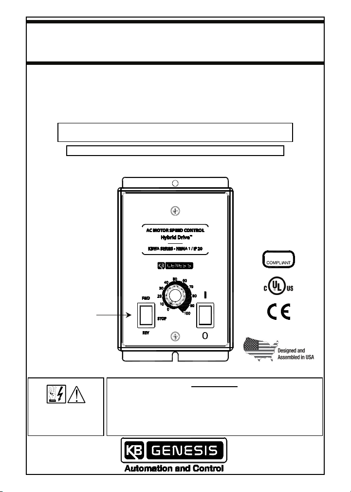
KBWA SERIES
HYBRID DRIVE™
Digital Drive with Analog Interface
KBWA-23D: NEMA 1 / IP20 (Vented) Enclosure
KBWA-22D, 21D, 2P6D, 2P3D: NEMA 1 / IP50 (Non Vented) Enclosure
Subfractional thru 1/2 HP 3-Phase AC and PSC* Induction Motors
Operates from 115 and 208/230 Volt 50/60 Hz AC Line Input
Provision for
Forward-Stop-Reverse
Switch (supplied).
(See Sec. 6, on p. 18)
*Operation with
PSC Motors requires
factory programming.
This Manual Covers Models KBWA-23D, 22D, 21D, 2P6D, 2P3D
SEE
SAFETY WARNING
ON PAGE 2
Rated for 208 – 230 Volt 50 and 60 Hz
Variable Speed / Soft Start
with Electronic Motor Overload Protection
AC Line Input Voltage Setting: The drive is factory set for
208/230 Volt AC Line input. For 115 Volt AC Line input, see
Section 7.1, on page 19.
Motor Frequency Setting: The drive is factory set for 60 Hz
Motors. For 50 Hz Motors, see Section 4.1, on page 13.
IMPORTANT
RoHS
Copyright © 2014
KB Electronics, Inc.
(see back cover)
SAFETY WARNING
Definition of Safety Warning Symbols
Electrical Hazard Warning Symbol: Failure to observe this warning could result
in electrical shock or electrocution.
Operational Hazard Warning Symbol: Failure to observe this warning could
result in serious injury or death.
This product must be installed and serviced by a qualified technician,
electrician, or electrical maintenance person familiar with its operation and the
hazards involved. Proper installation, which includes electrical connections,
fusing or other current protection, and grounding, can reduce the chance of
electrical shocks, and/or fires, in this product or products used with this
product, such as electric motors, switches, coils, solenoids, and/or relays. Do
not use this drive in an explosion-proof application. Eye protection must be
worn and insulated adjustment tools must be used when working with drive
under power. This product is constructed of materials (plastics, metals,
carbon, silicon, etc.) which may be a potential hazard. Proper shielding,
grounding, and filtering of this product can reduce the emission of radio
frequency interference (RFI) which may adversely affect sensitive electronic
equipment. It is the responsibility of the equipment manufacturer and
individual installer to supply this Safety Warning to the ultimate end user of
this product. (SW 8/2012)
The drive contains electronic Start/Stop circuits, which can be used to start
and stop the drive. However, these circuits are never to be used as safety
disconnects since they are not fail-safe. Use only the AC Line for this purpose.
Be sure to read and follow all instructions carefully. Fire and/or electrocution
can result due to improper use of this product.
KBWA-23D: NEMA 1 / IP20 (Vented) Enclosure
KBWA-22D, 21D, 2P6D, 2P3D: NEMA 1 / IP50 (Non Vented) Enclosure
ITEMS INCLUDED IN THIS PACKAGE
Description Part No.
Drive —
Installation and Operation Manual A40179
Accessories Bag: Jumper Wire for J3 (to Set the Drive for 115 Volt AC Line
Input), Trimpot Adjustment Tool, Extra 6-32 X 3/8" Cover Screw, Status
Indicators Label, and two Universal Bushings.
Switch Kit Bag: Forward-Stop-Reverse Switch Assembly, Two Wire Ties,
and Installation Instructions.
Mounting Template A42326
Warranty Registration Card A40101
2
F36869
F36868

QUICK-START INSTRUCTIONS
1. REMOVE THE COVER: The cover must be removed to setup and wire the drive.
See Section 5.1, on pages 16 and 17.
2. AC LINE INPUT SELECTION: The drive is factory set for 208/230 Volt AC Line
input (Jumper J3 not installed). Install the supplied jumper to set the drive for
115 Volt AC Line input. See Section 7.1, on page 19.
3. MOTOR FREQUENCY SELECTION: Jumpers J1 and J2 are both factory set for
60 Hz motors. For other motors, see Section 7.2, on pages 19 – 21.
4. START MODE SELECTION: The drive is factory set for Automatic Start Mode
(jumper installed onto CON1). To operate the drive in the Manual Start Mode, the
supplied Forward-Stop-Reverse Switch must be installed. See Section 7.3, on
pages 21 and 22.
5. FORWARD/REVERSE SPEED SELECTION: The drive is factory set for Forward
Speed Operation (CON1 jumper installed in the "F" position). For Reverse Speed
Operation, set the CON1 jumper in the "R" position. See Section 7.4, on page 22.
Note: As an alternate to using the F-S-R jumper, reverse any two motor leads
(with the AC Line disconnected and the motor stopped).
6. ADJUSTABLE TRIMPOTS: All trimpots have been factory set for most
applications. See Section 12, on pages 28 – 31.
7. MOUNTING THE DRIVE: See Section 8, on page 23.
8. AC LINE INPUT, MOTOR AND GROUND CONNECTIONS: At Terminal Block
TB1, wire the AC Line input to "L1 and "L2"; the ground wire(s) to "GND"; and the
motor to "U", "V", and "W". See Section 10, on pages 24 – 26.
9. FORWARD-STOP-REVERSE SWITCH (SUPPLIED): Install the switch, if
required. See Section 6, on page 18.
10. INSTALL THE COVER: After the drive has been setup, mounted, and wired,
install the cover. See Section 5.2, on page 17.
This product complies with all CE directives pertinent at the time of
manufacture. Contact our Sales Department for Declaration of Conformity.
Installation of a CE approved RFI filter is required. Additional shielded cable and/or
AC Line cables may be required.
Note: In order for this drive to meet CE requirements, a separate CE approved filter
must be installed.
UL NOTICE
115 Volt Drives:
Suitable for use on a circuit capable of delivering not more than
5 kA RMS symmetrical Amperes. 115 Volts maximum. Use copper conductors rated
75 °C. Suitable for operation in a maximum surrounding air temperature of 40 °C.
230 Volt Drives: Suitable for use on a circuit capable of delivering not more than
5 kA RMS symmetrical Amperes. 230 Volts maximum. Use copper conductors rated
75 °C. Suitable for operation in a maximum surrounding air temperature of 40 °C.
3

TABLE OF CONTENTS
Section Page
1 FAMILIARIZING YOURSELF WITH THE DRIVE .................................................7
2 ELECTRICAL RATINGS AND SPECIFICATIONS...............................................9
3 INTRODUCTION .................................................................................................10
3.1 Standard Features ..................................................................................11
3.2 Performance Features............................................................................11
3.3 Protection Features ................................................................................12
3.4 Selectable Jumpers................................................................................12
3.5 Adjustable Trimpots...............................................................................12
3.6 Customization for OEMs........................................................................13
4 IMPORTANT APPLICATION INFORMATION ....................................................13
4.1 50 Hz Motors ...........................................................................................13
4.2 Motor Current Setting ............................................................................ 13
4.3 Motor with External Fan Cooling ..........................................................14
4.4 Electronic Motor Overload Protection..................................................15
5 REMOVING AND INSTALLING THE COVER ....................................................16
5.1 Removing the Cover...............................................................................16
5.2 Installing the cover.................................................................................17
6 INSTALLING THE SUPPLIED FORWARD-STOP-REVERSE SWITCH
(REQUIRED FOR MANUAL START MODE)......................................................18
7 SETTING SELECTABLE JUMPERS ..................................................................19
7.1 AC Line Input Voltage Selection (Jumper J3) ......................................19
7.2 60 Hz and 50 Hz Motor Operation and Drive Output Frequency
Selection (Jumpers J1 and J2) ..............................................................19
7.2.1 Setting the Drive for 60 Hz and 50 Hz Motor Operation...........19
7.2.2 Setting the Drive for Two Times the Rated Motor RPM ...........20
7.3 Automatic and Manual Start Mode (CON1) ..........................................21
7.3.1 Automatic Start Mode .................................................................21
7.3.2 Manual Start Mode ......................................................................22
7.4 Forward/Reverse Speed Selection (CON2) ..........................................22
8 MOUNTING .........................................................................................................23
9 RECONDITIONING THE BUS CAPACITORS ....................................................24
4

TABLE OF CONTENTS (CONTINUED)
Section Page
10 ELECTRICAL CONNECTIONS...........................................................................24
10.1 AC Line Input and Ground .....................................................................25
10.2 Motor and Ground ..................................................................................25
10.3 AC Line Input Fusing .............................................................................26
11 HIGH VOLTAGE DIELECTRIC WITHSTAND TEST (HI-POT)...........................27
12 TRIMPOT ADJUSTMENTS.................................................................................28
12.1 Minimum Speed Trimpot (MIN)..............................................................29
12.2 Maximum Speed Trimpot (MAX) ...........................................................29
12.3 Acceleration Trimpot (ACC) ..................................................................29
12.4 Deceleration Trimpot (DEC) ...................................................................30
12.5 Slip Compensation Trimpot (COMP) ....................................................30
12.6 Current Limit Trimpot (CL).....................................................................31
13 DRIVE OPERATION............................................................................................32
13.1 Start-Up Procedure.................................................................................32
13.2 Fault Recovery........................................................................................32
13.3 Restarting the Drive After An Overload Fault Has Cleared ................33
14 DIAGNOSTIC INDICATORS ...............................................................................33
14.1 Illuminated On/Off AC Line Switch .......................................................34
14.2 Power On LED (PWR) .............................................................................34
14.3 Status LED (ST).......................................................................................34
LIMITED WARRANTY.................................................................................. Back Cover
Table Page
1 Electrical Ratings.................................................................................................9
2 General Performance Specifications .................................................................9
3 Factory Setting of Current Limit (CL) Trimpot ................................................13
4 Terminal Block TB1 Wire and Tightening Torque Specifications .................25
5 DC Hi-Pot Tester Setup Information.................................................................27
6 Fault Recovery and Resetting the Drive ..........................................................33
7 Operating Condition and Status LED Indicator ..............................................34
5

TABLE OF CONTENTS (CONTINUED)
Figure Page
1 Cover Layout ........................................................................................................7
2 Drive Layout .........................................................................................................8
3 Maximum Allowed Motor Torque vs. Speed....................................................14
4 Open Ventilated Motor with External Fan Cooling .........................................15
5 Cover Positioned On Top of Case....................................................................17
6 Forward-Stop-Reverse Switch Installation ......................................................18
7 AC Line Input Voltage Selection.......................................................................19
8 60 Hz and 50 Hz Motor Selection ......................................................................20
9 Available Torque vs. Output Frequency ..........................................................20
10 120 Hz and 100 Hz Drive Output Frequency Selection ...................................21
11 Automatic Start ..................................................................................................21
12 Manual Start .......................................................................................................22
13 Forward/Reverse Speed Selection ...................................................................22
14 Mechanical Specifications ................................................................................23
15 AC Line Input, Motor, and Ground Connections ............................................26
16 Typical Hi-Pot Test Setup..................................................................................28
17 Minimum Speed Trimpot (MIN) Range .............................................................29
18 Maximum Speed Trimpot (MAX) Range ...........................................................29
19 Acceleration Trimpot (ACC) Range ..................................................................29
20 Deceleration Trimpot (DEC) Range ..................................................................30
21 Slip Compensation Trimpot (COMP) Range ....................................................30
22 KBWA-23D CL Trimpot Range..........................................................................31
23 KBWA-22D CL Trimpot Range..........................................................................31
24 KBWA-21D CL Trimpot Range..........................................................................31
25 KBWA-2P6D CL Trimpot Range .......................................................................31
KBWA-2P3D CL Trimpot Range .......................................................................31
26
6
1 FAMILIARIZING YOURSELF WITH THE DRIVE
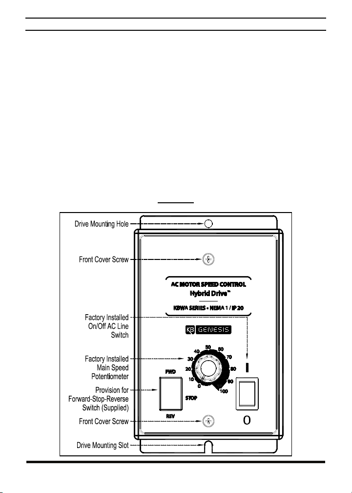
The drive has a factory installed On/Off AC Line Switch and a Main Speed
Potentiometer. It also has provision for a Forward-Stop-Reverse Switch (supplied).
See Figure 1. Remove the cover to access the drive's jumpers, connectors, adjustable
trimpots, and the terminal block to wire the AC Line input, Motor, and Ground
connections. See Figure 2, on page 8.
Removing and Installing the Cover: See Section 5, on pages 16 and 17.
Forward-Stop-Reverse Switch (Supplied): See Section 6, on page 18.
Selectable Jumpers: See Section 7, on pages 18 – 22.
Mounting: See Section 8, on page 23.
Electrical Connections: See Section 10, on pages 24 – 26.
Trimpot Adjustments: See Section 12, on pages 28 – 31.
Drive Operation: See Section 13, on pages 32 and 33.
Diagnostic Indicators: See Section 14, on pages 33 and 34.
FIGURE 1
COVER LAYOUT
7
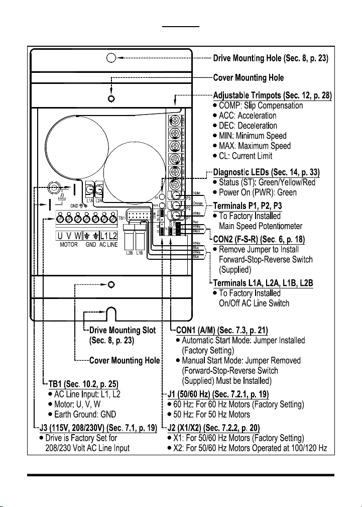
FIGURE 2
(SHOWN WITH COVER REMOVED)
DRIVE LAYOUT
8

2 ELECTRICAL RATINGS AND SPECIFICATIONS
TABLE 1
ELECTRICAL RATINGS
Model No.
(Part No.)
KBWA-23D
(9946)
KBWA-22D
(9926)
KBWA-21D
(9925)
KBWA-2P6D
(9923)
KBWA-2P3D
(9922)
Maximum
Horsepower
(HP (kW))
1/2 (0.37)
1/4 (0.18)
1/10 (0.07)
Subfractional
Subfractional
AC Line Input Drive Output Net Wt.
Volts AC
(50/60 Hz)
115 1 8.8 15 2.2
208 / 230 1 6.0 10 2.4
115 1 5.2 10 1.3
208 / 230 1 3.8 5 1.5
115 1 4.0 5
208 / 230 1 2.5 5
115 1 2.4 5
208 / 230 1 1.5 2
115 1 1.2 2
208 / 230 1 0.75 1
Phase
(Ф)
Maximum
Current
(Amps AC)
Fuse or
Circuit
Breaker
Rating
(Amps)
Maximum
Continuous
Load Current
(RMS Amps)
Maximum
Voltage
(Volts AC) lbs kg
230 1.6 0.72
230 1.5 0.68
1.0 230 1.5 0.68
0.6 230 1.5 0.68
0.3 230 1.5 0.68
TABLE 2
GENERAL PERFORMANCE SPECIFICATIONS
Factory
Description Specification
115 Volt AC Line Input Voltage Operating Range (Volts AC) 115 (±15%) —
208/230 Volt AC Line Input Voltage Operating Range (Volts AC)
Maximum Load (% Current Overload for 2 Minutes) 150 —
Switching Frequency (kHz) 8 —
Output Frequency Resolution (Bits, Hz) 10, 0.06 —
Minimum Speed Trimpot (MIN) Range (% Frequency Setting) 0 – 40 0
Maximum Speed Trimpot (MAX) Range (% Frequency Setting) 70 – 110 100
Acceleration Trimpot (ACC) Range (Seconds) 0.3 – 20 1.5
Deceleration Trimpot (DEC) Range (Seconds) 0.3 – 20 1.5
Slip Compensation Trimpot (COMP) Range at Drive Rating (Volts/Hz) 0 – 3 1.5
Current Limit Trimpot (CL) Range (% Drive Rating) 60 – 190 160
Motor Frequency Setting (Hz) (Jumper J1) 50, 60 60
Output Frequency Multiplier (X1, X2) (Jumper J2)1
Minimum Operating Frequency at Motor (Hz) 1 —
Speed Range (Ratio) 60:1 —
Speed Regulation (30:1 Speed Range, 0 – Full Load) (% Base Speed)2
Overload Protection (I2t) Trip Time for Stalled Motor (Seconds) 6 —
AC Line Input Undervoltage/Overvoltage Trip Points
For 115 Volt AC Line (±5%) (Volts AC)
AC Line Input Undervoltage/Overvoltage Trip Points
for 208/230 Volt AC Line (±5%) (Volts AC)
Operating Temperature Range (°C / °F) 0 – 40 / 32 – 104 —
Operating Humidity Range (% Relative, Non-Condensing) 0 – 95 —
Storage Temperature (°C / °F)
3
3
208 (-15%) /
230 (+15%)
1, 2 1
2.5 —
76 – 141 —
151 – 282 —
-25 – +85 /
-13 – +185
Setting
208/230
—
Notes: 1. Allows the motor to operate up to two times the rated RPM. Constant
horsepower will result when operating the drive in the "X2" Mode. 2. Dependent on
motor performance. 3. Do not operate the drive outside the specified AC line input
voltage operating range.
9

3 INTRODUCTION
Thank you for purchasing the KBWA Series Hybrid Drive. KB Electronics, Inc. is
committed to providing total customer satisfaction by providing quality products that
are easy to install and operate.
The KBWA Series are Digital Drives with Analog Interface. Model KBWA-23D is
housed in a NEMA 1 / IP20 vented enclosure. Models KBWA-22D, 21D, 2P6D, 2P3D
are housed in a NEMA 1 / IP50 non vented enclosure. They are designed to operate
subfractional thru 1/2 HP 208 – 230 Volt 50 & 60 Hz 3-phase AC and PSC induction
1
Flux Vector Control provides high torque, low noise, and excellent load
motors.
regulation over a wide speed range. Adjustable Linear Acceleration and Deceleration
make the drive suitable for soft-start applications.
Due to its user-friendly design, the drive is easy to install and operate. Tailoring to
specific applications is accomplished with selectable jumpers and trimpots, which
eliminate the computer-like programming required on other drives. However, for most
applications no adjustments are necessary.
Main Features: Adjustable RMS Current Limit and I
2
t Motor Overload Protection.2
Flux Vector Control with Static Auto-Tune provides high torque and excellent load
regulation over a wide speed range. Power Start™ delivers over 200% motor torque
to ensure startup of high frictional loads. Electronic Inrush Current Limit (EICL™)
eliminates harmful AC line inrush current. The drive is suitable for machine or variable
torque (HVAC) applications. A terminal block is provided to facilitate AC line input,
motor, and ground connections. Adjustable trimpots (MIN, MAX, ACC, DEC, COMP,
CL). Customer selectable jumpers (Automatic/Manual Start, Motor Frequency,
Frequency Multiplier, Forward/Reverse, and Line Voltage). PC board mounted
diagnostic LEDs provide indication of power on (PWR) and drive status (ST). The
drive includes a factory installed Main Speed Potentiometer and an illuminated On/Off
AC Line Switch. The drive also has provision for a Forward-Stop-Reverse Switch
(supplied) for reversing applications.
Options: Custom software for OEM applications. This drive can also be factory
programed to operate with GFCIs – contact our Sales Department.
Notes: 1. Operation with PSC motors requires factory programming – contact our
Sales Department. 2. UL approved as an overload protector for motors.
10

3.1 STANDARD FEATURES
Model KBWA-23D: Housed in a NEMA 1 / IP20 vented enclosure.
Models KBWA-22D, 21D, 2P6D, 2P3D: Housed in a NEMA 1 / IP50 non vented
enclosure.
Dual Voltage AC Line Input Operation: The drive operates from 115 and 208/230
Volt 50/60 Hz AC Line input. See Section 7.1, on page 19.
Simple to Operate: Does not require programming. Uses trimpots and jumpers,
which are factory set for most applications.
Factory Installed On/Off AC Line Switch: The switch illuminates when power is
applied to the drive and the switch is in the on position.
Factory Installed Main Speed Potentiometer: Provides adjustment of motor
speed.
Diagnostic LEDs: Power on (PWR) and drive status (ST). See Sections 14.2 and
14.3, on page 34.
Jumper Selection for Drive Output Frequency (Jumpers J1 and J2): Increases
motor speed up to two times the rated RPM. See Section 7.2, on pages 19 – 21.
Jumper Selection for Automatic and Manual Start (CON1): With the jumper
installed, the drive will automatically start after a fault has been cleared. With the
jumper removed, the drive must be manually restarted, after a fault has been
cleared. The supplied Forward-Stop-Reverse Switch must be installed for Manual
Start Operation. See Section 7.3, on pages 21 and 22.
Jumper Selection for Motor Direction (CON2): Allows selection of Forward or
Reverse direction. See Section 7.4, on page 22. The supplied
Forward-Stop-Reverse Switch can be installed to provide motor reversing and stop,
as described in Section 6, on pages 16 and 17.
Forward-Stop-Reverse Switch (Supplied): Easily Installs in the drive. See Section
6, on page 18.
3.2 PERFORMACE FEATURES
Power Start™: Provides more than 200% starting torque which ensures startup of
high frictional loads.
Flux Vector Control with Static Auto-Tune: Provides excellent load regulation
over a wide speed range.
Speed Range: 60:1
11
 Loading...