


KBPC-225
INSTALLATION AND OPERATING INSTRUCTIONS
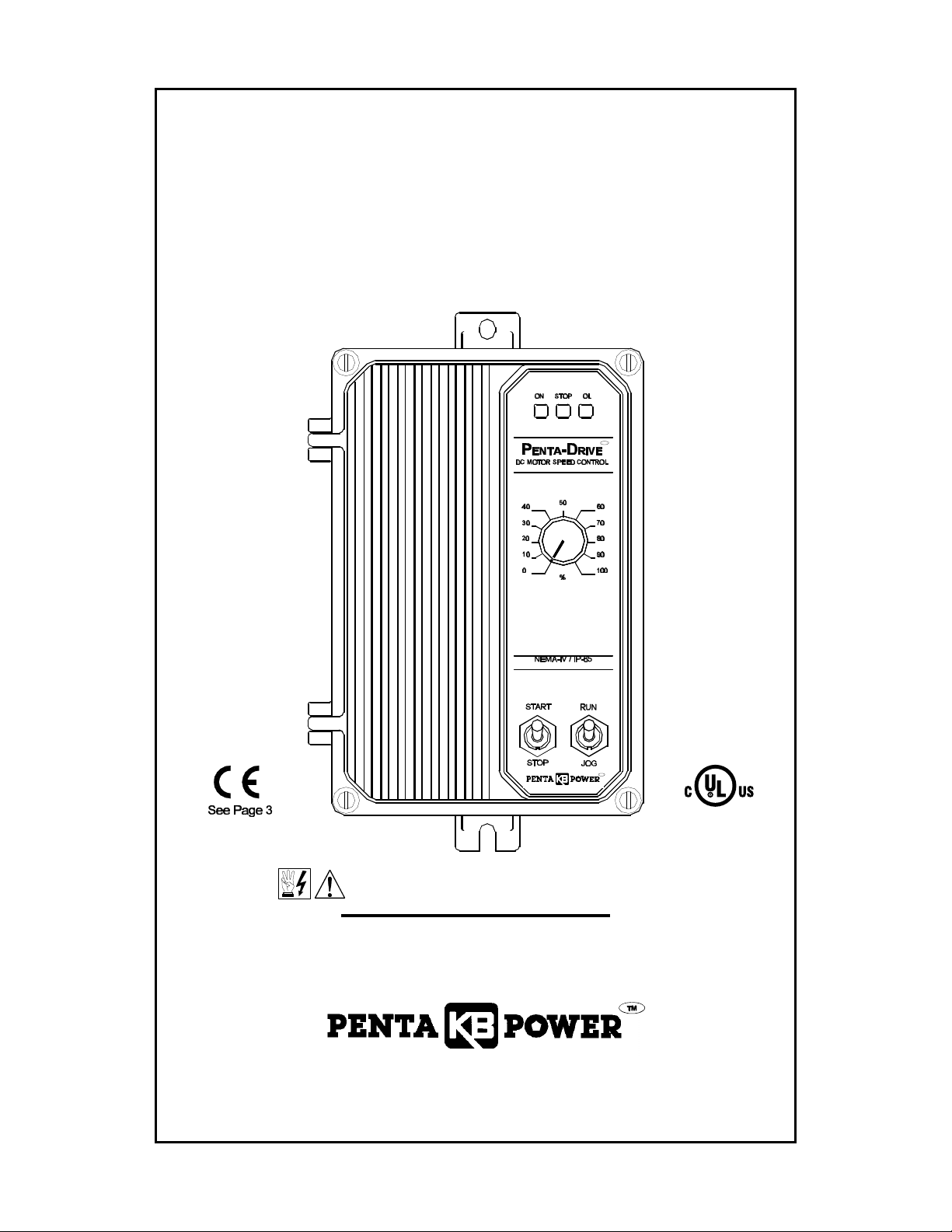
KBPC-225
SCR SPEED AND TORQUE CONTROL
NEMA 4X, IP-65
DESIGNED FOR SHUNT WOUND & PM DC MOTORS
RATED 3 HP @ 180 VDC
TM
TM
See Safety Warning on Page 3
The information contained in this manual is intended to be accurate. However, the manufacturer retains
the right to make changes in design which may not be included herein.
(Shown with optional Run-Stop-Jog Switch)
A COMPLETE LINE OF MOTOR DRIVES
© 1998 KB Electronics, Inc.

TABLE OF CONTENTS
Section Page
i. Safety Warning .........................................................3
ii. Simplified Operating Instructions ............................................3
I. General Information .....................................................3
II. Setting Speed or Torque Mode of Drive (Jumper J1) ............................6
III. Setting Selectable Jumpers ...............................................6
IV. Mounting ..............................................................7
V. Wiring ................................................................8
VI. Fusing ...............................................................10
VII. Operation ............................................................11
VIII. Trimpot Adjustments ....................................................11
IX. Function Indicator Lamps ................................................12
X. Optional Accessories ...................................................13
XI. Limited Warranty .......................................................20
TABLES
1. Electrical Ratings .......................................................4
2. General Performance Specifications .........................................4
3. Field Connections (Shunt Wound Motors Only) ................................8
4. Parts List ............................................................16
FIGURES
1. Control Layout .........................................................5
2a. Motor Speed vs. Potentiometer Rotation ......................................6
2b. Preset Motor Speed vs. Motor Load .........................................6
3a. Motor Output Torque vs. Potentiometer Rotation ...............................6
3b. Motor Speed vs. Applied Motor Load ........................................6
4a. Captive Screw Tightened In Case ...........................................8
4b. Captive Screw Engaged In Front Cover ......................................8
5. Connection Diagram .....................................................8
6a. Full Voltage Field .......................................................9
6b. Half Voltage Field .......................................................9
7. Tachometer Connection Diagram ...........................................9
8a. Remote Potentiometer Connection .........................................10
8b. Analog Voltage Connection ...............................................10
9. Remote Start/Stop Switch Connection ......................................10
10a. Inhibit Circuit Wiring ....................................................10
10b. Enable Circuit Wiring ...................................................10
11. Mechanical Specifications ................................................14
12. Schematic ............................................................15
13. Internal Connection Diagram ..............................................17
14. Connection Diagrams KBPC-225 With KBSI-240D (Signal Isolator) ................18
2

i. SAFETY WARNING! — PLEASE READ CAREFULLY
This product should be installed and serviced by a qualified technician, electrician or
electrical maintenance person familiar with its operation and the hazards involved. Proper
installation, which includes wiring, mounting in proper enclosure, fusing or other overcurrent
protection and grounding, can reduce the chance of electric shocks, fires or explosion in this
product or products used with this product, such as electric motors, switches, coils, solenoids
and/or relays. Eye protection must be worn and insulated adjustment tools must be used when
working with control under power. This product is constructed of materials (plastics, metals,
carbon, silicon, etc.) which may be a potential hazard. Proper shielding, grounding and filtering
of this product can reduce the emission of radio frequency interference (RFI) which may adversely
affect sensitive electronic equipment. If information is required on this product, contact our factory.
It is the responsibility of the equipment manufacturer and individual installer to supply this safety
warning to the ultimate user of this product. (SW effective 11/92)
This control contains electronic Start/Stop and Inhibit circuits that can be used to start and
stop the control. However, these circuits are never to be used as safety disconnects since they
are not fail-safe. Use only the AC line for this purpose.
The input circuits of this control (potentiometer, start/stop, Inhibit) are not isolated from AC
line. Be sure to follow all instructions carefully. Fire and/or electrocution can result due to
improper use of this product.
This product complies with all CE directives pertinent at the time of manufacture. Contact
of a CE approved RFI filter (KBRF-200, KB P/N 9945 or equivalent) is required. Additional shielded
motor cable and/or AC line cables may be required along with a signal isolator (KBSI-240D, KB
P/N 9431 or equivalent).
factory for detailed installation instructions and Declaration of Conformity. Installation
ii. KBPC-225 SIMPLIFIED OPERATING INSTRUCTIONS
IMPORTANT – You must read these simplified operating instructions before you proceed. These
instructions are to be used as a reference only and are not intended to replace the detailed
instructions provided herein. You must read the Safety Warning before proceeding.
1. Connections.
A. AC Line. Wire AC line voltage (230 VAC - 50/60 Hz) to terminals L1 and L2. Connect ground
wire (earth) to Green Screw on case.
B. Motor.
a. Permanent Magnet (PM) Type: Connect motor armature leads to terminals A1(+) and
A2(–).
b. Shunt Wound Motors: Connect motor armature as above. Connect full voltage shunt field
wires (180 volt motors with 200 volt fields) to F1 and F2. Connect half voltage field wires
(180 volt motors with 100 volt fields) to F1 and L1.
2. Speed or Torque Mode – Jumper J1 is factory set for speed control operation ("SPD"). For
torque control, set J1 to "TRQ" position.
3. Trimpot Settings – All trimpots have been factory set in accordance with Fig. 1 and Table 2.
4. Diagnostic LEDs – After power is turned on, observe LEDs to verify proper control function.
5. Fusing – Install 25 amp - 250 VAC fuses in both the AC Line and armature leads. See Section
VI (p. 10, 11).
I. GENERAL INFORMATION.
The KBPC Series Nema 4 X (IP-65) is a unidirectional SCR DC Motor Speed and Torque Control
designed for applications requiring watertight integrity, including washdown. Its housing is
ruggedly constructed of die cast aluminum, protected with an acrylic coating that provides
excellent corrosion resistance. All switches are sealed with rubber boots and the main speed
potentiometer contains a shaft seal.
3

The electronics for the KBPC is state-of-the-art and includes short circuit and transient
protection which provides the ultimate in reliability. Electronic overload protection prevents
motor burnout and demagnetization of PM motors. The control can be operated in either the
Speed or Torque mode via jumper selection.
Standard features include electronic start/stop and an LED indicator array for Power On, Stop
and Overload.
Although the KBPC is factory set for most applications, a variety of trimpots allow adjustment
of the following parameters: Minimum and Maximum Speed, Acceleration, Deceleration,
Current Limit, IR Comp, and Timed Current Limit. Optional features offered are: Run-Stop-Jog,
and Input Signal Isolation.
TABLE 1 – ELECTRICAL RATINGS
Model
Number
KBPC-225 230 0 – 200 22.0 15 3 (2.25)
Input Line
Voltage
(VAC-50/60Hz)
Armature
Voltage
(VDC)
Maximum Ac
Load Current
(RMS Amps)
Maximum DC
Load Current
(DC AMPS)
Maximum
Power HP (KW)
TABLE 2 – KBPC-225 GENERAL PERFORMANCE SPECIFICATIONS
PARAMETER (units) SPECIFICATIONS
AC Line Input (VAC ± 15%, 50/60 Hz) 230 —
Horsepower at 230 VAC Line (HP) [KW] 3 [2.25] —
Armature Voltage Range at 230 VAC Line (VDC) 0 - 200
Field Voltage at 230 VAC Line (VDC) 200/100
Ambient Temperature Range (ºC) 0 - 45 —
Speed Range (Ratio) 50:1
Load Regulation [Armature Feedback] (% Base Speed) ±1 —
Load Regulation [Tachometer Feedback] (% Set Speed) ±1 —
AC Line Voltage Regulation ( % Base Speed) ±0.5 —
ACCEL and DECEL Ranges (Seconds) 0.1 - 15 1
(1)
(2)
(3)
FACTORY
SETTING
180 VDC
—
—
MIN SPEED Range ( % Base Speed) 0 - 30 0
MAX SPEED Range (% Base Speed) 60 - 120 90
IR COMP Range at 230 VAC Line (VDC) 0 - 30 8
CL Range ( % Range Setting) 0 - 180 150
Timed CL Range (Seconds) 0.5 - 15 7
Voltage Following Linearity (% Base Speed) ±0.5
Notes:
(1) Maximum recommended output voltage is 180 VDC at 230 VAC. Exceeding this output
voltage will cause a reduction in load regulation performance.
(2) For shunt wound motor with lower field voltage, use F1 and L1 connection.
(3) Consult motor manufacturers for constant torque speed range of motor. (Typical speed
range for most 3 HP motor is 20:1)
4
—
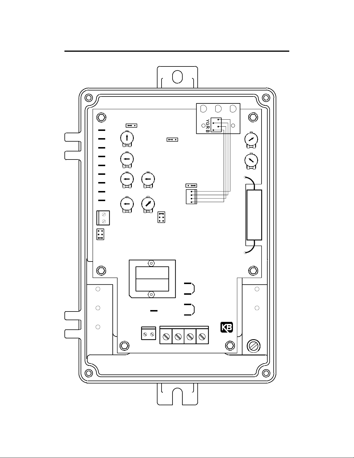
FIG. 1 – CONTROL LAYOUT
Illustrates Approximate Factory Setting of Jumpers and Trimpots
STOP OL
SPDTRQ
CONN1
ON
LED BOARD
CL
IR
TB3
J6
I1
I2
START
COM
STOP
JOG
P3
P2
DECEL ACCEL
P1
TT+
50V
20/30V
7V
J5
KBPC
NTCLTCL
TCL
JOG
MAXMIN
5V10V
J7
J1
180V
90V
T
J3
R69
TB2
T1
F+
F2F1
A1 A2 L1 L2
A1B
J8A
A1A
A2B
J8B
A2A
(1)
(1)
GND
(EARTH)
TB1
DWG#: B2800-1-00890
5

II. SETTING SPEED OR TORQUE MODE OF DRIVE (JUMPER J1)
A. Speed Control Mode – When Jumper J1 is placed in the "SPD" position the drive will
control motor speed as a linear function of the main potentiometer rotation or analog
voltage input. The range of output speed can be adjusted with the MIN and MAX trimpots.
The motor will maintain the preset speed as long as the maximum load does not exceed
the current limit set point. If the motor load exceeds the current limit setting, the Overload
LED will turn on and the motor will stall.
FIG. 2A – MOTOR SPEED vs.
POTENTIOMETER ROTATION
100
MOTOR
OUTPUT
SPEED
(%)
0
POTENTIOMETER ROTATION (%)
100
FIG. 2B – PRESET MOTOR SPEED vs.
MOTOR LOAD
100
PRESET
MOTOR
SPEED
(%)
0
100
MOTOR LOAD
150
CURRENT LIMIT STARTS
LED LIGHTS
B. Torque Control Mode – When Jumper J1 is placed in the "TRQ" position, the drive will
control motor torque as a linear function of main potentiometer rotation. If the motor load
exceeds the torque setting, the motor will stall, the Overload LED will light, and the drive
will apply a constant preset torque based on the potentiometer setting. The Overload LED
will light when the load torque approaches the current limit set point. The torque limits are
set via the CL trimpot. Note: When operating in the Torque Mode, Jumper J5 must be in
the "NTCL" position or drive will shut down when CL Timer times out.
FIG. 3A – MOTOR OUTPUT TORQUE vs.
POTENTIOMETER ROTATION
150
FIG. 3B – MOTOR SPEED vs. APPLIED
MOTOR LOAD
100
S1
HIGHER TORQUE
SETTING
S3
S2
TORQUE
SETTING
100
MOTOR
OUTPUT
TORQUE
(%)
MOTOR
SPEED
(%)
LOWER TORQUE
0
POTENTIOMETER ROTATION (%)
100
SETTING
0
APPLIED MOTOR LOAD (%) TORQUE
III. SETTING SELECTABLE JUMPERS
This control has selectable jumpers which can be changed to accommodate various
applications. Note: Jumpers J2 and J4 have not been installed in this control. Jumper J1
is set in accordance with Section II. Refer to Figure 1.
C. Tachometer Feedback (J3) – The control is factory set for armature feedback which
provides good load regulation for most applications. If superior load regulation is required,
tachometer feedback can provide over 1% load regulation over a 50:1 speed range. If
tachometer feedback is to be used, J3 must be placed in the "TFB" position and an external
DC tachometer must be connected. See Sections III C. (p. 7) and V E. (p. 9) for additional
information. Note: IR Comp trimpot must be turned to minimum position (full ccw).
6
 Loading...