

Page 1
“The Right Control for Your Application.”
12095 NW 39 Street, Coral Springs, FL 33065-2516
KB Electronics, Inc. Telephone: 954-346-4900; Fax: 954-346-3377
.%9)0XOWL6SHHG%RDUG,QVWDOODWLRQ:LULQJDQG2SHUDWLQJ,QVWUXFWLRQV
This document is supplied with the KBVF Multi-Speed Board (Part No. 9503).
LEDs are no longer illuminated.
Warning! Before installing the Multi-Speed Board onto the KBVF, disconnect the AC power and wait until the "PWR" and "ST"
IMPORTANT: The KBVF Multi-Speed Board Data Sheet D-802, KBVF Installation and Operation Manual, and these instructions must be read
and understood before attempting to operate this control. For further assistance, contact our Sales Department at 954-346-4900 or Toll Free
at 800-221-6570 (outside Florida).
Tools required: small wire cutter and small flat blade screwdriver.
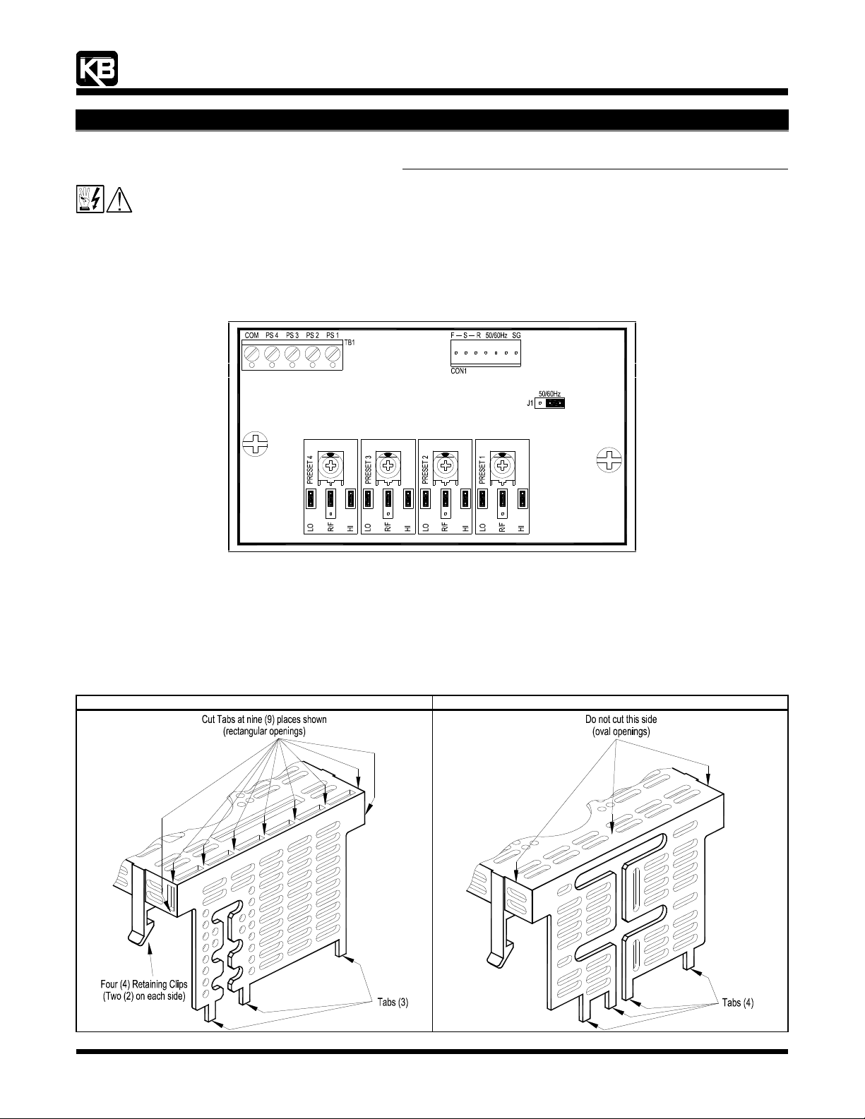
Figure 1 - KBVF Multi-Speed Board Control Layout
1 Removing and Modifying the Finger-Safe Cover (FSC) on the KBVF - See Figure 2.
If using the FSC, it needs to be modified to install the MSB, as described below. If the FSC is not used, proceed to Section 2, on page 2.
1.1 Remove the FSC, by gently lifting up on all four (4) retaining clips.
1.2 Using cutters, cut off the end section with three (3) Tabs at nine (9) places. Do not cut off the end section with four (4) Tabs.
1.3 Before installing the FSC onto the KBVF, make all connections from the MSB to the KBVF, as described in Section 3, on page 2.
Note: On some KBVF models, the FSC is supplied with a separate side panel which is already removed.
Figure 2 - Modifying the Finger-Safe Cover
End Section with Three (3) Tabs End Section with Four (4) Tabs
(A42136) - Rev. B00 - 11/02/2004 - Z3269B00 Page 1 of 4
Page 2
“The Right Control for Your Application.”
12095 NW 39 Street, Coral Springs, FL 33065-2516
KB Electronics, Inc. Telephone: 954-346-4900; Fax: 954-346-3377
.%9)0XOWL6SHHG%RDUG,QVWDOODWLRQ:LULQJDQG2SHUDWLQJ,QVWUXFWLRQV
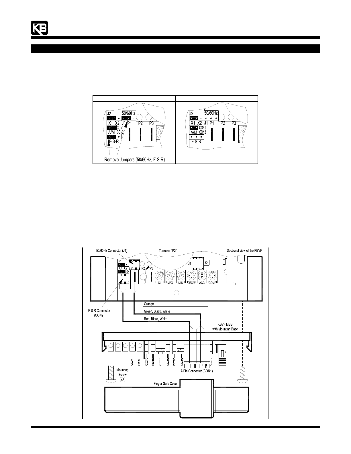
2 Preparing the KBVF Prior to Installing the MSB - See Figure 3.
Remove and discard the jumpers that are installed on J1 (50/60Hz) and CON2 (F-S-R) on the KBVF.
Figure 3 - Preparing the KBVF Prior to Installing the MSB
Before After
PWR
ST
PWR
ST
3 Installing and Wiring the MSB - See Figure 4.
3.1 Insert the two 6-32 X ½" screws (provided) through the mounting holes on the MSB and align them with the threaded mounting
holes on the side of the heat sink of the KBVF (located on the side nearest the trimpots).
3.2 Using the flat blade (or Phillips) screwdriver, gently tighten the two screws to secure the MSB to the heat sink (8 in-lbs max.). Do
not overtighten.
3.3 Install the connector with green/black/white wires onto J1 (50/60Hz).
3.4 Install the connector with red/black/white wires onto CON2 (F-S-R).
3.5 Install the terminal with orange wire onto Terminal "P2".
Figure 4 - Installing and Wiring the MSB
PWR
ST
230V 115V
(A42136) - Rev. B00 - 11/02/2004 - Z3269B00 Page 2 of 4
Page 3

“The Right Control for Your Application.”
12095 NW 39 Street, Coral Springs, FL 33065-2516
KB Electronics, Inc. Telephone: 954-346-4900; Fax: 954-346-3377
.%9)0XOWL6SHHG%RDUG,QVWDOODWLRQ:LULQJDQG2SHUDWLQJ,QVWUXFWLRQV
4 MSB Operating Instructions
4.1 A preset speed is selected with a contact closure or open collector wired between "COM" and either "PS 1", "PS 2", "PS 3", or "PS
4" of Terminal Block TB1. Wire the contact or open collector as shown in Figure 5.
Wire Guage Range (AWG - Cu): 24 - 14. Maximum Tightening Torque: 3.5 in-lbs.
(Note: The maximum operating current for each preset is 1.5 mA DC.)
Figure 5 - MSB Terminal Block TB1 Connection Diagrams
Switch Form C Contacts Open Collector
4.2 Motor direction for each preset is selected by the position of Jumper R/F (Reverse/Forward). All presets have been factory set for
Forward Motor Direction (Jumpers R/F set to the "F" position). See Figure 6.
Figure 6 - Motor Direction Selection (Jumper R/F)
Forward Motor Direction
(Factory Setting) Reverse Motor Direction
(Jumper R/F In "F" Position) (Jumper R/F In "R" Position)
4.3 To improve the resolution of the trimpots, several ranges are provided. The motor speed range for each preset is selected with
Jumpers HI and LO. All speed range jumpers have been factory set for Full Speed Range (Jumpers LO and HI installed). See
Figure 7. (Note: The maximum speed is based on the MAX Trimpot setting.)
Figure 7 - Speed Range Selection (Jumpers LO and HI)
Full Speed Range
(0 - 100 % of MAX Speed)
(Factory Setting)
(Jumper LO Installed)
(Jumper HI Installed)
Low Speed Range
(0 - 50 % of MAX Speed)
(Jumper LO Installed)
(Jumper HI Not Installed)
Medium Speed Range
(33 - 66 % of MAX Speed)
(Jumper LO Not Installed)
(Jumper HI Not Installed)
High Speed Range
(50 - 100 % of MAX Speed)
(Jumper LO Not Installed)
(Jumper HI Installed)
4.4 The speed for each preset can be fine tuned using the adjustable trimpots. All trimpots have been factory set for 50% speed. See
Figure 8. (Note: The maximum speed is based on the MAX Trimpot setting.)
Figure 8 - Speed Trimpot Range
% of Range Setting
(Factory Set to 50%)
(A42136) - Rev. B00 - 11/02/2004 - Z3269B00 Page 3 of 4
Page 4

“The Right Control for Your Application.”
12095 NW 39 Street, Coral Springs, FL 33065-2516
KB Electronics, Inc. Telephone: 954-346-4900; Fax: 954-346-3377
.%9)0XOWL6SHHG%RDUG,QVWDOODWLRQ:LULQJDQG2SHUDWLQJ,QVWUXFWLRQV
4.5 Motor frequency is selected using J1 (50/60Hz) on the MSB and J2 (X1, X2) on the KBVF. The control is factory set to operate 60
Hz motors (J1 is factory set to the "60Hz" position and J2 is factory set to the "X1" position). See Figure 3. To operate 50 Hz
motors, set J1 to the "50Hz" position. (Be sure that J2 is set to the "X1" position.) See Figure 9.
Overspeed Mode: To operate 60 Hz motors up to 120 Hz, be sure that J1 is set to the "60Hz" position and set J2 to the "X2"
position. To operate 50 Hz motors up to 100 Hz, set J1 to the "50Hz" position and set J2 to the "X2" position.
Note: In Overspeed Mode, the motor will produce full rated torque up to the motor’s rated frequency. Operating the motor above it’s
rated frequency will linearly reduce the motor torque to 50% at full output frequency (120 Hz for 60 Hz motors and 100 Hz for 50 Hz
motors).
Figure 9 - Motor Frequency Selection
Motor Frequency Rating J1 on the MSB J2 on the KBVF
60 Hz *
50 Hz
120 Hz
100 Hz
* Factory setting.
(A42136) - Rev. B00 - 11/02/2004 - Z3269B00 Page 4 of 4
 Loading...