

Page 1
INSTALLATION AND OPERATING INSTRUCTIONS
REGENERATIVE DRIVE
MODEL KBRG-225D
(P/N 8800)
FULL WAVE • 4 QUADRANT
FWD
FWD
REV
ACCEL
ACCEL
EN
REV
EN
PWR
ON
T1
DB
OFFSET
S/LT
NLT
MODEL KBRG-240D
(P/N 8802)
MAX
J8
IR REV FWD
RESPSPD
CLCOMP
CL
TCL
This manual
applies to
logic board
revision “L”
and newer
controls
only.
CL
ARMATURE
FUSE
TB2
M2L1 L2
F2
F1
(EARTH)
GND
TB1
21 3 4 65
TB1
F+ F-
F1
AC LINE
FUSE
R33
J3
1297 8 10 11 13
M1
See Safety Warning on Page 2
The information contained in this manual is intended to be accurate. However, the manufacturer
retains the right to make changes in design which may not be included herein.
See Page 2
™
A COMPLETE LINE OF MOTOR DRIVES
© 1997 KB Electronics, Inc.
Page 2

TABLE OF CONTENTS
Section Page
i. Simplified Setup and Operating Instructions ...................................1
ii. Safety Warning .........................................................2
I. General Information .....................................................2
II. Setting Mode of Drive (Speed or Torque Control) ...............................4
III. Setting Selectable Jumpers ...............................................6
IV. Mounting ..............................................................8
V. Wiring ................................................................8
VI. Fusing ...............................................................12
VII. Operation ............................................................12
VIII. Trimpot Adjustments ....................................................13
IX. Function Indicator Lamps ................................................15
X. Limited Warranty .......................................................22
TABLES
1. Electrical Ratings .......................................................2
2. General Performance Specifications .........................................4
3. Summary of Control Operation .............................................5
4. Jumper J2 Position vs Motor Horsepower .....................................6
5. Relationship of AC Line Input and Motor Voltage ...............................7
6. Terminal Block Wiring Information ..........................................8
7. Field Connections ......................................................10
8. Control State vs Relay Contact State .......................................12
9. Armature Fuse Chart ...................................................13
10. Current Limit Timer Settings ..............................................15
11. Parts List (Logic Board) ..............................................16, 17
12. Parts List (Power Board) .................................................19
FIGURES
1. Control Layout .........................................................3
2A. Linear Torque Curve .....................................................5
2B. Non-Linear Torque Curve .................................................6
3. AC Line Voltage Jumper Setting ............................................7
4. Motor Armature Voltage Jumper Setting ......................................7
5. Mechanical Specifications .................................................9
6. AC Line and Armature Connection .........................................10
7A. Full Voltage Field ......................................................10
7B. Half Voltage Field ......................................................10
8. Main Speed Potentiometer Connections .....................................11
9A. Voltage Following ......................................................11
9B. Enable ..............................................................11
9C. Start/Stop Circuit .......................................................11
9D. Alarm Contacts ........................................................11
9E. Tach-generator Connection ...............................................12
10. Accel Trimpot Adjustment ................................................13
11. Offset Trimpot Adjustment ...............................................14
12. Deadband Trimpot Adjustment ............................................14
13. Logic Board Schematic ..................................................18
14. Power Board Schematic .................................................20
ii
Page 3

i. KBRG SIMPLIFIED OPERATING INSTRUCTIONS
IMPORTANT – You must read these simplified operating instructions
before you proceed. These instructions are to be used as a reference
only and are not intended to replace the detailed instructions provided
herein. You must read the Safety Warning on page 2 before proceeding.
1. CONNECTIONS.
A. AC Line – Wire AC line voltage to terminals L1 and L2. Be sure jumpers J1A and
J1B are both set to the correct input line voltage of 115 or 230 VAC. Connect
ground wire (earth) to green ground screw.
B. Motor.
1. Permanent Magnet (PM Type). Connect motor armature leads to M1+ and M2-.
Be sure jumper J3 is set to the proper position “90" for 90 volt DC motors and
“180" for 180 volt DC motors. Note: 180 volt DC motors must be used with 230
VAC line, 90 volt motors can be used with a 230 VAC or 115 VAC line. Note:
Motor performance and efficiency, including brush life, may be adversely
affected when using 90 volt motors with a 230 VAC line.
2. Shunt Wound Motors. Connect motor armature as above. Connect full voltage
shunt field wires (90 volt motors with 100 volt fields and 180 volt with 200 volt
fields) to F+ and F-. Connect half voltage field wires (90 volt motors with 50 volt
fields and 180 volt motors with 100 volt fields) to F+ and L1.
2. SPEED OR TORQUE MODE.
Jumper J7 is factory set for speed control operation (SPD). For torque control, set J7
to TRQ position. Note: J8 must be set to the “S/LT” position for speed control operation.
3. MOTOR CURRENT.
Jumper J2 is factory set for 15 amp motors (15A) on the KBRG-225D and 10 amp motors
(10A) on the KBRG-240D. For lower amperage motors, place J2 in the proper position.
If motor amperage is less than 2.5 amps, which is the lowest value on both models, use
the 2.5A position and readjust the IR and both CL trimpots according to section VIII D
and E on pages 14 and 15 .
Note: The factory setting for Current Limit is 150% of the nominal current setting (e.g.,
if J2 is selected for 5 amps, the actual CL setting will be 7.5 amps).
4. TRIMPOT SETTINGS.
All trimpots have been factory set in accordance with figure 1, page 3.
5. AC LINE FUSE.
The power board on all models contains a single AC line fuse (F1), 25A for KBRG-225D
and 20A for KBRG-240D. The AC line fuse protects the unit from catastrophic failure.
6. ARMATURE FUSE.
An armature fuse (F2) is also provided. A 25A armature fuse is installed on the
KBRG-225D and a 20A on the KBRG-240D. It is recommended that the correct size
armature fuse be installed depending on the rating of the motor and form factor. See
table 9, page 13.
7. SIGNAL INPUT.
Connect potentiometer or isolated analog input to terminal “10,” “11,” “12" and “13"
according to section V, E and F, on pages 10 and 11. Do not ground (earth) signal
inputs. Use a signal isolator when controlling multiple drives from a non isolated signal
source.
1
Page 4
ii. SAFETY WARNING! — PLEASE READ CAREFULLY
This product should be installed and serviced by a qualified technician, electrician or
electrical maintenance person familiar with its operation and the hazards involved. Proper
installation, which includes wiring, mounting in proper enclosure, fusing or other overcurrent
protection and grounding, can reduce the chance of electric shocks, fires or explosion in this
product or products used with this product, such as electric motors, switches, coils, solenoids
and/or relays. Eye protection must be worn and insulated adjustment tools must be used when
working with control under power. This product is constructed of materials (plastics, metals,
carbon, silicon, etc.) which may be a potential hazard. Proper shielding, grounding and filtering
of this product can reduce the emission of radio frequency interference (RFI) which may
adversely affect sensitive electronic equipment. If information is required on this product,
contact our factory. It is the responsibility of the equipment manufacturer and individual installer
to supply this safety warning to the ultimate user of this product. (SW effective 11/92)
This control contains electronic Start/Stop and Inhibit circuits that can be used to start and
stop the control. However, these circuits are never to be used as safety disconnects since they
are not fail-safe. Use only the AC line for this purpose.
The input circuits of this control (potentiometer, start/stop, Inhibit) are not isolated from AC
line. Be sure to follow all instructions carefully. Fire and/or electrocution can result due
to improper use of this product.
This product complies with all CE directives pertinent at the time of manufacture.
Contact factory for detailed installation instructions and Declaration of
Conformity. Installation of a CE approved RFI filter (KBRF-200A, KB P/N 9945C or
equivalent) is required. Additional shielded motor cable and/or AC line cables may be
required along with a signal isolator (SI-4X, KB P/N 8801 or equivalent).
I. GENERAL INFORMATION.
The KBRG is a full-wave regenerative control, capable of operating a DC motor (Permanent
Magnet or Shunt) in a bidirectional mode. It provides 4-quadrant operation which allows
forward and reverse torque in both speed directions. The drive offers excellent controllability,
which closely approximates the performance of servo-type drives. Ratings and specifications
are presented in tables 1 and 2. Be sure the drive is used within these ratings and
specifications.
(Note: Regenerative drives normally produce more motor heating than standard
unidirectional SCR speed controls, especially under low speed operation. This should
be taken into consideration when specifying motor rating.)
WARNING! Be sure to follow all instructions carefully. Fire or electrocution
can result due to improper use of this product. Read Safety Warning.
TABLE 1 – ELECTRICAL RATINGS
Model Part No.
KBRG-240D 8802
KBRG-225D 8800
Input
Voltage
(VAC)
115 16 0 – ±90 11 1, (.75)
230 16 0 – ±180 11 2, (1.5)
115 24 0 – ±90 16 1, (1)
230
Max. AC
Current
(RMS)
24
Output
Voltage
(VDC)
0 – ±180
Max. DC
Output
Current (ADC)
16
Horsepower
Max.
HP, (KW)
3, (2)
2
Page 5
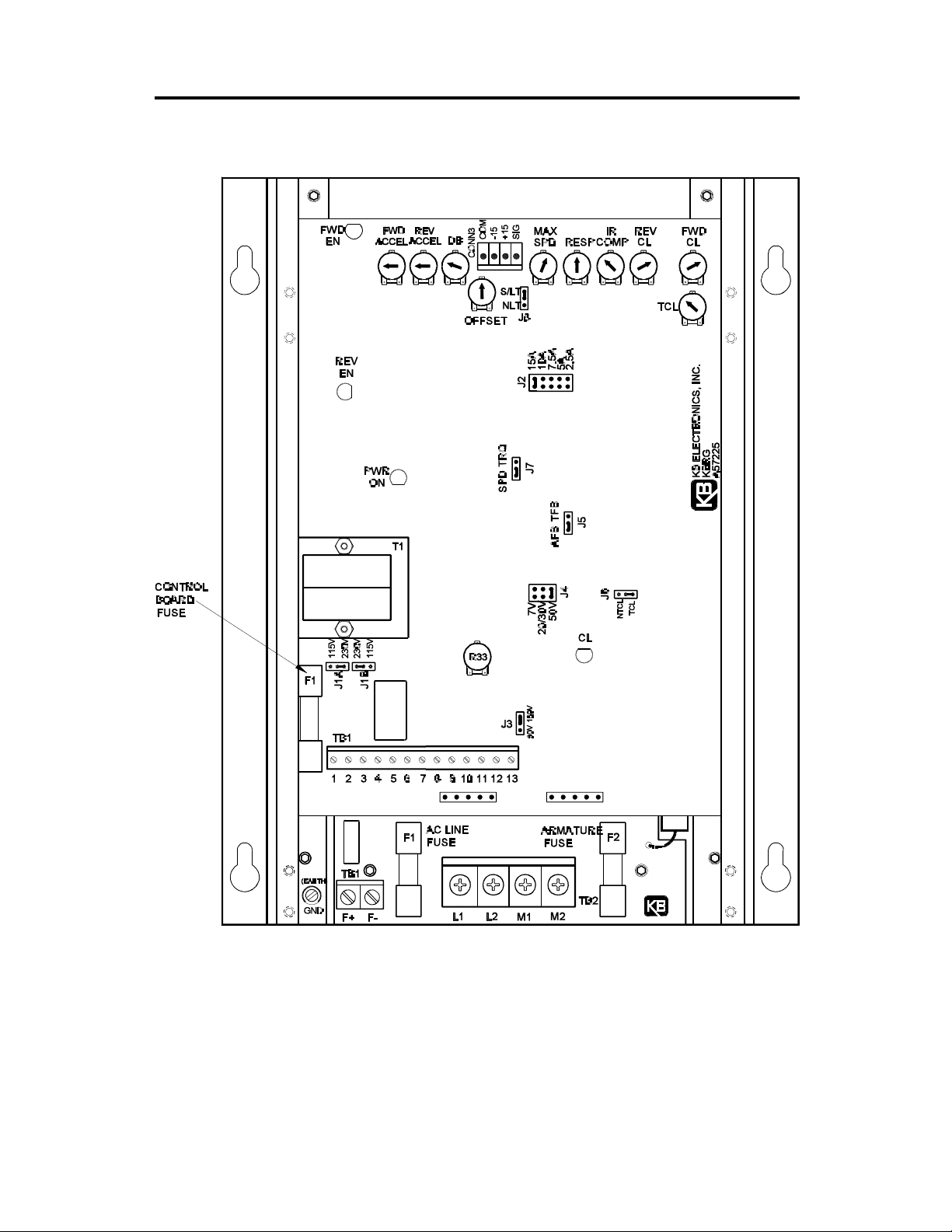
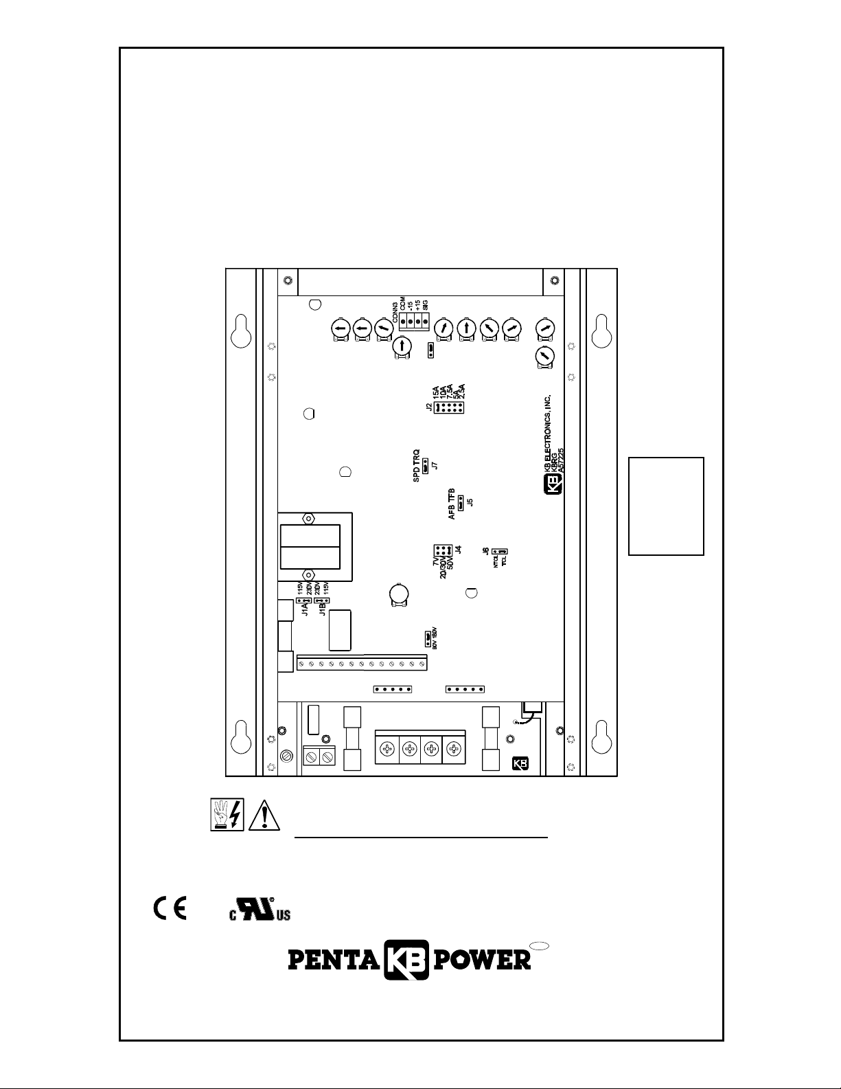
FIG. 1 – CONTROL LAYOUT
Illustrates Factory Setting of Jumpers and Approximate Trimpot Settings
3
Page 6

TABLE 2 – GENERAL PERFORMANCE SPECIFICATIONS
Parameter Specification Factory Setting
AC Line Input Voltage (VAC ±10%,50/60 Hz)
AC Line Frequency (Hz), # of Phases
Arm Voltage Range at 115VAC Line (VDC)
Arm Voltage Range at 230VAC Line (VDC)
Field Voltage at 115VAC Line (VDC)
Field Voltage at 230VAC Line (VDC)
Service Factor
Duty
Max Load Capacity (% for 2 minutes)
Ambient Temperature Range (ºC)
Speed Range (Ratio)
Arm Feedback Load Regulation (% Base Speed)
Tach Feedback Load Regulation (% Set Speed)
Line Regulation (% Base Speed)
Current Ranges (ADC)
FWD and REV Accel Range (Secs.)
Dead Band Range (% Base Speed)
Max Speed Trimpot Range (% Base Speed)
IR Comp Range at 115VAC Line (VDC)
IR Comp Range at 230VAC Line (VDC)
FWD and REV CL Range (% Range Setting)
Timed CL Range (Sec.)
Voltage Following Input Range (VDC)
Voltage Following Linearity (% Base Speed)
Tach-generator Voltage Input (Volts)
115 or 230
50/60, 1
0 – ±90
0 – ±180, 0 – ±90
100/50
200/100
1.0
Continuous
150
(1)
0 – 50
50:1
±1
±1
±0.5
2.5, 5.0, 7.5, 10, 15
0.1 – 15
0 – ±3
70 – 110
0 – 15
0 – 30
0 – 150
1 – 15
0 – ±10, 0 – ±15
±0.5
7,20/30,50
(2)
230
—
—
0 – ±180
—
—
—
—
—
—
—
—
—
—
15 or 10
1
0
100
5
10
150
5
0 – ±15
—
50
Notes:
(1) Control mounted in vertical position. Maximum ambient temperature in horizontal position is 45 ºC.
(2) 15A current range on KBRG-225D only.
II. SETTING MODE OF DRIVE (SPEED OR TORQUE CONTROL).
The KBRG can be operated as a speed control or torque control by setting the position of
jumper J7. The main speed potentiometer controls the magnitude of the mode selected. Set
jumper J7 to "SPD" for speed control or to "TRQ" for torque control. (See fig. 1, p. 3.)
A. Speed Control Mode – When jumper J7 is set to the “SPD” position, the KBRG will vary
the motor speed as a function of the voltage on input terminals "12" (signal) and "13"
(common). IMPORTANT: When J7 is set for speed control (“SPD”), J8 must be set to
“S/LT” position (factory setting). The input voltage can be derived from the wiper of the
main speed potentiometer or from an isolated analog input (voltage following mode). Since
the KBRG is a 4-quadrant regenerative drive, the motor speed will follow both a positive
and negative wiper voltage and drive the motor in both the forward direction and reverse
direction. In addition, it will apply both forward and reverse torque in order to stabilize motor
speed.
To understand the concept of a regenerative drive, the operation of an elevator can be used.
If one were to enter the elevator on the first floor and press 10, the motor and control would
have to lift the elevator against gravity. In this mode, the drive would operate like a
conventional speed control which is called “motoring” (the applied load is opposite to the
direction of motor rotation). When the elevator is at floor 10 and floor 1 is pressed, gravity will
try to pull the elevator car down faster than the speed for which it is set. The control will then
provide reverse torque to keep the car form falling faster than the set speed. This operation
is regeneration (the applied load is in the same direction as the direction of motor rotation).
Table 3 on page 5 summarizes the different modes of regen operation.
4
Page 7

TABLE 3 – SUMMARY OF CONTROL OPERATION
Quadrant
I Motoring CW CW CCW
II Regeneration CCW CW CCW
III Motoring CCW CCW CW
IV Regeneration CW CCW
Type of
Operation
Motor Rotation
Direction
Motor Torque
Direction
Applied Load
Direction
CW
B. Torque Control Mode – When Jumper J7 is set to “TRQ” position, the KBRG will vary
motor torque. The KBRG has been redesigned and now contains two (2) types of torque
characteristics which are selectable with jumper J8. Speed/Linear Torque (S/LT) and Non
Linear Torque (NLT). In the “S/LT” position (factory setting), both output torque and
motor speed vary linearly as a function of the input signal. The “S/LT” type of torque is
most suitable for take up and pay out winders where the speed and torque requirements
vary as the winder roll diameter changes. The “S/LT” torque characteristics are shown in
fig. 2A.
FIG. 2A – LINEAR TORQUE CURVE
In the “NLT” position, only torque (not speed) is varied by the input signal. The motor
output torque remains constant over the motor’s full speed range unless the load is less
than the set torque. If the load torque decreases below the set torque, the motor will
rapidly increase to full speed. This type of torque control is applicable to processes where
the torque must remain constant over a wide motor speed range. The “NLT” torque
characteristics are shown in fig. 2B p. 6.
Because the KBRG is a regenerative control, torque will be applied in both forward and
reverse directions. The maximum torque can be set with the FWD CL and REV CL
trimpots, and by using the FWD ACCEL and REV ACCEL trimpots, the rate of change of
torque can be made more or less gradual. The maximum speed trimpot can be used to
set the maximum motor speed under a no load condition.
5
Page 8

FIG. 2B – NON-LINEAR TORQUE CURVE
III. SETTING SELECTABLE JUMPERS.
The KBRG has customer selectable jumpers which must be set before the control can be used
(refer to fig. 1 p. 3). Bold indicates Factory Setting. (See sec. II, p. 4 for J7 and J8 settings.)
A. J1A, J1B - Input AC Line Voltage – Select proper input line voltage, 115VAC or 230VAC,
by placing both jumpers (J1A and J1B) in the correct corresponding position, "115" or
"230." See fig. 3.
B. J2 - Armature Current – Select the J2 position (2.5, 5, 7.5, 10, 15) closest to the rated
motor current. (Note: The maximum output current is set to 150% of the J2 position, which
may be readjusted using the FWD CL and REV CL trimpots.) Note: On Model
KBRG-240D, position 10A is factory setting.
TABLE 4 – JUMPER J2 POSITION vs MOTOR HORSEPOWER
15A
10A
7.5A
5.0A
2.5A
J2
Jumper J2 Position
Motor Current
(DC Amps)
(1)
15A
10A 1 2
7.5A 3/4 1
5.0A 1/2, 1/3 1, 3/4
2.5A 1/4 1/2
Motor Horsepower
90VDC 180VDC
1 3
(1) 15A current range on KBRG-225D only.
C. J3 - Motor Armature Voltage – Select the desired armature voltage by placing J3 in the
proper position, "90" or "180." Note: For 115 volt AC line input, the armature voltage must
be set to "90." For 230 input, the armature voltage normally is set for "180." However, it
is also possible to set the armature voltage to "90" for step-down operation.
6
Page 9

FIG. 3 – AC LINE VOLTAGE
JUMPER SETTING
115VAC 230VAC 90VDC 180VDC
FIG. 4 – MOTOR ARMATURE
VOLTAGE JUMPER SETTING
TABLE 5 – RELATIONSHIP of AC LINE INPUT AND MOTOR
VOLTAGE with J1A, J1B and J3 JUMPER POSITION
AC INPUT VOLTAGE
115 115 90 90
230 230 180 180
230 230 90* 90*
J1A, J1B
POSITION
J3 POSITION MOTOR VOLTAGE
*A 90VDC motor can be used with a 230VAC line. However, speed range may be reduced and
motor overheating may result.
D. J4 - Tach-generator Voltage – (Note: Selection of the jumper position is not required if
armature feedback is used.) Place J4 jumper in the position "7V", "20/30V," "50V" that
corresponds to the tach-generator voltage in Volts/KRPM. Note: The tach voltage jumper
position is based on motor speed of 1,800 RPM.
For example, if the tach is 25V/KRPM and the motor speed is 3,600 RPM, use the "50V"
J4 position. For other tach-generator voltages and motor speeds, an external resistor
(RT) may be used as follows.
i. Install resistor in series with either tach-generator lead.
ii. Place J4 in "7V" position.
iii. The value of RT is calculated as follows.
RT = [(5.4 x Vt x S) - 68,000] VT = Tach voltage in volts/1000 RPM
Choose the closest standard watt S = Base Speed of motor in RPM
resistor value to the calculated value
E. J5 - Feedback Type – The KBRG can be operated in either armature feedback "AFB"
or tach-generator feedback "TFB." Armature feedback provides adequate load regulation
for most applications. For very precise performance, tach-generator feedback "TFB"
should be used. (Note: If tach feedback is desired, an external DC tach-generator must
be used and connected as per instructions.) (See section V J, p. 12 for tach-generator
wiring.) (Note: The IR Comp trimpot must be set to the minimum setting [CCW] for tach
feedback.)
F. J6 - Current Limit (CL) Mode – The KBRG contains electronic current limiting that limits
the maximum DC current to the motor. (Note: Current Limit is established with the
selection of the J2 position and the setting of the Forward and Reverse CL trimpots "FWD
CL" and "REV CL.")
7
Page 10

Two modes of current limit are provided:
1. Timed Current Limit "TCL" – Turns the drive off after a preset time. (The time period
is adjustable with the TCL trimpot from 1-15 seconds and is factory set for
approximately 5 seconds.) In order for the Timed CL feature to operate, the
Start/Stop circuit must be wired. To restart drive after it has "timed out," the Start
button must be pressed.
Application Note: The “TCL” feature cannot be used in either torque mode, since
nuisance tripping will occur.
2. Non-Timed Current Limit "NTCL" – In this mode, the drive will reach preset Current
Limit during overload and stay at that level until drive is turned "off" or fuse blows. If
Non-Timed CL is desired, move jumper J6 from the factory set "TCL" position to the
"NTCL" position.
IV. MOUNTING.
Mount the KBRG in a vertical position (connection terminals in down or up position) on a flat
surface free of moisture, metal chips, or corrosive atmosphere. (Note: If drive is mounted in
other than a vertical position, decrease maximum allowable ambient temperature by 10 ºC.)
(See Outline Drawing fig. 1, p. 3.) A 5K ohm Remote Speed potentiometer is provided with
each control. Install potentiometer using hardware provided. Be sure to install insulating disk
between potentiometer and inside of front panel.
Enclosure – When mounting the KBRG in an enclosure, it must be large enough to allow for
proper heat dissipation. A 12"x12"x24" enclosure is suitable for the KBRG-240D at full rating
and a 12"x24"x36" enclosure is suitable for the KBRG-225D at full rating. Smaller enclosures
may be used if full rating is not required.
V. WIRING. Warning! Read Safety Warning before attempting to use this control.
Warning! To avoid erratic operation do not bundle AC Line and motor wires with
potentiometer, voltage following, enable, inhibit or other signal wiring. Use shielded
cables on all signal wiring over 12" (30 cm) – Do not ground shield.
Wire control in accordance with National Electric Code requirements and other local codes
that apply. The KBRG contains a single AC line fuse wired in series with terminal L1. Be sure
to fuse each conductor which is not at ground potential (do not fuse neutral or grounded
conductors). (See section VI, p. 12, for fuse information.) Wire control in accordance with
connection diagram (see fig. 8 and 9, p. 11). A separate AC line switch or contactor must be
wired as a disconnect switch to control so that contacts open each ungrounded conductor.
See table 6.
TABLE 6 – TERMINAL BLOCK WIRING INFORMATION
Terminal Block
Designation
TB1 (Power Board) F+, F- 22 14 3.5
TB1 (Logic Board) Logic Connections 22 14 3.5
TB2 L1, L2, M1, M2 18 10 12
Connection
Designation
Supply Wire Gauge*
Minimum Maximum
Maximum Tightening
Torque (lbs inch)
*AWG, Cu wire only.
A. AC Line – Connect AC line to terminals L1 and L2. (Be sure jumpers J1A and J1B are
set to match the AC line voltage used. See table 4, p. 6.) See fig. 6, p. 10.
B. Motor Armature – Connect motor armature to terminal M1 and M2. (Be sure jumper J3
is set to match motor voltage. See table 4, p. 6.) See fig. 6, p. 10.
8
Page 11

0.30
(7.62)
10.00
(254.00)
1.00
(25.40)
8.00
(203.20)
FIG. 5 – MECHANICAL SPECIFICATIONS
7.70
(195.58)
7.10
(180.34)
T1
INCHES
[mm]
R0.089
[R2.3]
0.324
[8.2]
R0.172
[R4.4]
(4 PL)
(4 PL)
(4 PL)
3.440
[87.4]
F1
12
21 3 465
TB1
F+ F-
F1
AC LINE
FUSE
97 8 10 11
13
M1
ARMATURE
FUSE
TB2
M2L1 L2
F2
DWG#: C3900-1-00096
R69
NOTE: CONTROL SHOWN ABOVE IS MODEL KBRG-225D.
HEIGHT OF MODEL KBRG-240D IS 2.57" (65 mm).
9
Page 12

FIG. 6 – AC LINE AND ARMATURE CONNECTIONC. Field (For Shunt Wound
motors only) – Do not
use F+ and F- terminals for any
other motor type. Connect
motor shunt field to terminals
F+ and F- for 90VDC motors
with 100VDC fields and
180VDC motors with 200VDC
fields. For motors with half
voltage fields, 90VDC motors
with 50VDC fields and 180VDC
motors with 100 VDC fields,
connect field to terminals F+ and L1. See table 7 for
summary of Field Connections.
CAUTION – Shunt-Wound motors may be damaged if field remains connected
without motor rotating for an extended period of time.
FIG. 7A – FULL VOLTAGE FIELD FIG 7B – HALF VOLTAGE FIELD
TABLE 7 – FIELD CONNECTIONS (Shunt Wound Motors Only)
AC Line Voltage (VAC) Motor Voltage Field Voltage (VDC) Field Connection
115 90 100 F+, F115 90 50 F+, L1
230 180 200 F+, F230 180 100 F+, L1
230 90* 100
F+, L1
*Step down operation (see sec. III C, p. 6).
D. Ground – Be sure to ground (earth) the control via green screw located on chassis.
E. Main Speed Potentiometer – The main speed potentiometer can be connected in several
ways using terminals "10," "11," "12," "13." ( A 5K ohm potentiometer is supplied with
control. A 10K potentiometer can also be used.) [WARNING! Terminals “10,” “11,”
“12" and “13" are not isolated from AC line. Do not ground (earth).]
i. Unidirectional operation only – Connect potentiometer to terminals "10," "12," "13" for
forward direction. (To operate in reverse direction, connect to "11," "12," "13.")
ii. Bidirectional operation using reversing contacts – Connect to terminals "10," "11,"
"12," "13" as per fig. 8, p. 11.
iii. Bidirectional operation with potentiometer – Connect potentiometer to terminals "10,"
"11," "12" as per fig. 8, p. 11.
10
Page 13

FIG. 8 – MAIN SPEED POTENTIOMETER CONNECTIONS
FORWARD REVERSE
BIDIRECTIONAL
with REVERSING CONTACT
F. Voltage Following – An isolated analog voltage can be used in
lieu of main speed potentiometer. Connect signal to terminals "12"
BIDIRECTIONAL
with SPEED POT
FIG. 9A – VOLTAGE
FOLLOWING
and "13." Note: Terminal "13" is common. A positive signal with
respect to terminal "13" will produce a positive output to motor. A
negative signal with respect to terminal "13" will produce a
negative output. A 0 to ±10VDC is required to operate control
from 0 to ± full output. WARNING! Do not common multiple
drives without a signal isolator. A bipolar signal isolator, SI-4X,
is available as an option from your distributor.
G. Enable – Control may be electronically started and stopped with
Enable circuit. Connect Enable contacts between terminals "8"
and "9." When terminals "8" and "9" are joined, control is in
"ENABLE" state. When terminals "8" and "9" are open, control is in "INHIBIT" state. (See
fig. 9B.)
IMPORTANT! If Enable is not used, a jumper must be installed between terminals
"8" and "9" or control will not operate. (See Safety Warning on page 2.)
H. Start/Stop Circuit – A standard 3-wire start/stop circuit is provided (terminals "5," "6" and
"7"). This allows a remote momentary 2-button start/stop station to be installed. In this
mode, if AC power is removed, the start button must be used to restart the control. Also,
when the control is in the Timed Current Limit mode (J6 set to TCL) and has "timed out,"
it must be restarted using the start button. IMPORTANT! If the Start/Stop mode is not
required, a jumper must be installed between terminals "5" and "7." (Note: The Timed CL
function will operate only when the start/stop mode is used.) Control will not start using
Start/Stop circuit if AC line voltage is below 20% of nominal (95 volts on 115V circuit and
190V on 230V circuit). (See Safety Warning on page 2.)
FIG. 9B – ENABLE FIG. 9C – START/STOP CIRCUIT
FIG. 9D – ALARM CONTACTS
RY1
TB1
43
ALARM
CONTACTS
11
Page 14

I. Alarm Contacts – S.P.S.T. relay contacts (terminals "3" and "4") are used to signal a
warning or to shut other equipment down if control goes to an Inhibit state. Rating of
contacts are 1A-28VDC, .5A-115VAC. See table 8 for relay control state vs contact state.
(See fig. 9D, p. 11.)
TABLE 8 – CONTROL STATE vs RELAY CONTACT STATE
Relay Contact State
Description of Control State Using Start / Stop Start / Stop Bypassed
No power to control O O
Power applied O X
Control in Stop mode O NA
Control is started with Start button X NA
Control has “Timed Out” in TCL O NA
O – Open, X – Closed, NA – Not Applicable
J. Tach-generator Input – Terminals "1" and "2" are used
to connect a DC tach-generator and should be used only
when control is in tach-generator feedback mode (J5 is
in "TFB" position). Connect the positive (+) tach lead to terminal
"1" and the negative (-) tach lead to terminal "2." Note: The tachgenerator polarity must be phased so that the tach voltage is positive
(+) on terminal "1" when the voltage on terminal "12" is positive (+).
If the tach-generator is wired backwards, the control will run at full
speed only.
VI. FUSING.
A. Power Board.
1. AC Line Fuse – The Power Board on all models contains a single AC line fuse (F1) 25A
for KBRG-225D and 20A for KBRG-240D) which protects the unit from catastrophic
failure. CAUTION: Most electrical codes require that each ungrounded conductor
contain fusing. Separate branch circuit fusing may be required. Check local electrical
codes.
2. Armature Fuse – An armature fuse (F2) is also provided with a rating equal to the
maximum RMS rating of the control. It is recommended that the correct size armature
fuse be installed, depending on the rating of the motor and form factor (RMS/AVG
current). Fuse type should be Littlefuse 326 ceramic or Buss ABC, or equivalent. A
fuse chart is presented on page 13 (table 9) which suggests appropriate armature fuse
ratings. However, the specific application may require larger fuse ratings based on
ambient temperature, CL set point and duty cycle of operation (see table 9, p. 13).
Fuses may be purchased from your distributor.
FIG. 9E – TACH-GENERATOR
CONNECTION
B. Control Board Fuse – The logic control board contains a low amperage fuse (.150 amp
Littelfuse 3AG normal blo or equivalent) which protects the control transformer and other
components against catastrophic failure. Under normal circumstances, this fuse should
never blow. (See fig. 1, p. 3, for location.)
VII. OPERATION.
WARNING! Read Safety Warning on page 2 before attempting to operate or
severe injury or death can result.
After the KBRG has been set up (Jumpers are in appropriate position) and the drive has been
properly wired, the startup procedure can begin. Before initially starting, be sure main speed
pot is in minimum position. (Set main speed pot to full CCW position if wired for unidirectional
operation and to center position if wired for bidirectional control. (See fig. 8, p. 11.)
12
Page 15

TABLE 9 – ARMATURE FUSE CHART (F2 Power Board)
Motor Horsepower
90VDC 180VDC
1/8 1/4 1.3 2
1/6 1/3 1.7 2
1/4 1/2 2.5 4
1/3 3/4 3.3 5
1/2 1 5.0 8
3/4 1 7.5 12
1 2 10.0 15, 20*
1 3 15.0 25
Approx. DC Motor
Current Amps
Fuse Rating
(AC Amps)
* Use higher rated fuse for high ambient temperature or when rapid starting and stopping occur.
Start control by applying AC power. Enable circuit must be closed for control to start (jumper
terminals "8" and "9"). If wired for start/stop operation, press start switch. If not wired for
start/stop, terminals "5" and "7" must be jumpered. Rotate main speed potentiometer to control
motor speed.
VIII. TRIMPOT ADJUSTMENTS.
The KBRG contains many trimpots which have been factory adjusted for most applications.
(See table 2, p. 4. for factory settings.) (Note: fig. 1, p. 3 presents the various trimpots with
their locations. They are shown in the approximate adjustment position.) Some applications
may require readjustment of trimpots in order to tailor control to exact requirements. Readjust
trimpots as follows:
A. Forward Acceleration (FWD ACCEL) and Reverse Acceleration (REV ACCEL) – The
FWD ACCEL trimpot determines the amount of time it takes the control voltage to reach
full output in the forward direction. It also determines the amount of time it takes for the
control voltage, in the reverse direction, to reach zero output. (FWD ACCEL also sets the
Reverse Decel.)
The REV ACCEL trimpot determines the amount of time it takes the control voltage to
reach full output in the reverse direction and the time it takes for the control voltage, in the
forward direction, to reach zero output. (REV ACCEL is the Forward Decel.)
The FWD and REV ACCEL trimpots are factory adjusted to 1 second. The acceleration
times are adjustable to a maximum
FIG. 10 – ACCEL TRIMPOT ADJUSTMENT
of 15 seconds. (See fig. 10 for
graphic representation of ACCEL.)
Note: The FWD and REV CL trimpots settings may override the
rapid accel and decel settings.
Note: A 4-quadrant ACCEL/
DECEL accessory module is
available as an option. It provides
separate control of FORWARD
acceleration and deceleration and
REVERSE acceleration and
deceleration.
13
Page 16

B. Offset (OFFSET) – This trimpot
determines the amount of bias in the
forward or reverse direction. The
trimpot is factory set to provide approximately zero offset, which
means neither the forward nor the
reverse speed is favored. (See fig.
11 which illustrates the action of the
OFFSET trimpot.)
C. Deadband (DB) – The DB trimpot
sets the amount of main speed potentiometer rotation required to initiate control voltage output. It is factory adjusted to approximately 25%
of rotation.
The DB trimpot also determines the
amount of delay that will occur before regeneration starts. (Regeneration occurs when the applied load
torque is in the same direction as
the motor rotation.)
To readjust the DB to factory setting:
i. Set Main Speed pot to zero
speed position.
FIG. 11 – OFFSET TRIMPOT ADJUSTMENT
FIG. 12 – DEADBAND TRIMPOT ADJUSTMENT
ii. Set DB trimpot to full CCW posi-
tion.
iii. Adjust DB trimpot CW until mo-
tor hum is eliminated.
(See fig. 12 for graphic illustration of the DB trimpot.)
Note: If the deadband trimpot is set too low (CCW direction), the motor may oscillate
between forward and reverse. Adjust deadband trimpot CW until the instability
disappears. (Oscillation may also occur due to response setting. See section VIII, G, p.
15.)
D. Forward Current Limit (FWD CL) and Reverse Current Limit (REV CL) Trimpots –
These trimpots are used to set the maximum amount of DC current that the motor can
draw in both the forward and reverse directions. The amount of DC current determines
the amount of maximum motor torque in both the Speed Control Mode and Torque Control
Mode. They are factory set at 150% of the current established by the jumper J2 setting.
Readjust the CL trimpots as follows:
i. Turn CL trimpot to MIN (CCW) position. Be sure jumper J2 is in proper position
approximately equal to the motor DC ampere rating.
ii. Wire in a DC ammeter in series with armature lead. Lock shaft of motor.
iii. Apply power. Rotate CL trimpot CW until desired CL setting is reached (factory
setting is 1.5 times rated motor current). Be sure control is in Forward direction for
FWD CL trimpot adjustment and likewise with REV CL.
14
WARNING! Do not leave motor shaft locked for more than 2 – 3 seconds to prevent
motor damage.
CAUTION: Adjusting the CL above 150% of motor rating can cause overheating and
demagnetization of some PM motors. Consult motor manufacturer.
Page 17

E. IR Compensation (IR Comp) – The IR Comp is used to stabilize motor speed under
varying loads. (Note: If control is in Tach Feedback mode, the IR Comp should be set
to minimum - CCW.)
Readjust the IR Comp trimpot as follows:
i. Run motor at approximately 30-50% of rated speed under no load and measure actual
speed.
ii. Load motor to rated current. Rotate IR Comp trimpot so that loaded speed is the
same as the unloaded speed measured in the previous step.
Control is now compensated so that minimal speed change will occur over a wide range
of motor load. [Note: Too much IR Comp will cause unstable (oscillatory) operation.]
F. Maximum Speed (MAX) – The MAX trimpot is used to set the maximum output voltage
of the control which, in turn, sets the maximum speed of the motor. In the Torque Control
Mode, the MAX trimpot setting determines the unloaded motor speed. Adjust the MAX
trimpot as follows:
i. Rotate Main Speed potentiometer to full speed (CW).
ii. Adjust MAX trimpot to desired maximum motor speed.
(Note: Do not exceed maximum rated RPM of motor since unstable operation may result.)
G. Response (RESP) Trimpot – This trimpot determines the dynamic response of the control.
The factory setting is approximately 50% of full rotation. The setting may be increased if
a faster response is required. (Note: If response is made too fast, unstable operation may
result.)
H. Timed Current Limit (TCL) Trimpot – Trimpot is functional only when control is wired for
3-wire Start/Stop and J6 is in the TCL position. The TCL trimpot sets the delay time for the
Timed Current Limit. The trimpot is adjustable over a time range of 1-15 seconds and is
factory set for approximately 5 seconds. Calibrate the TCL trimpot by setting the trimpot
to the approximate desired delay time as follows: (See table 10.)
TABLE 10 – CURRENT LIMIT TIMER SETTINGS
Approx. Trip Time
(Secs)
1 Full CCW
8 Midway
15 Full CW
IX. FUNCTION INDICATOR LAMPS.
A. LED 1 Power On (PWR ON) – Indicates that the drive is energized with the AC line.
B. LED 2 Current Limit (CL) – Indicates that the drive is in Current Limit. If set in the timed
Current Limit mode (J6 set to "TCL") and has "timed out," the LED 2 will remain ON until
the drive is restarted.
C. LED 3 Forward Enable (FWD EN) – Indicates that the drive is engaged in the forward
direction. [Enable circuit closed (terminals "8" and "9" joined), the start circuit initiated and
a "forward" speed command.] The FWD EN lamp will also be lighted in the reverse direction
if the control is in regeneration.
Trimpot Position
D. LED 4 Reverse Enable (REV EN) – Indicates that the drive is engaged in the reverse
direction. [Enable circuit closed (terminals "8" and "9" joined), the start circuit initiated and
a "reverse" speed command.] The REV EN lamp will also be lighted in the forward direction
if the control is in regeneration.
15
Page 18

X – LIMITED WARRANTY
For a period of 18 months from date of original purchase, KB will repair or replace without
charge devices which our examination proves to be defective in material or workmanship.
This warranty is valid if the unit has not been tampered with by unauthorized persons,
misused, abused, or improperly installed and has been used in accordance with the
instructions and/or ratings supplied. The foregoing is in lieu of any other warranty or
guarantee, expressed or implied, and we are not responsible for any expense, including
installation and removal, inconvenience, or consequential damage, including injury to any
person, caused by items of our manufacture or sale. Some states do not allow certain
exclusions or limitations found in this warranty so that they may not apply to you. In any
event, KB's total liability, under all circumstances, shall not exceed the full purchase price
of this unit. (rev 4/88)
KB ELECTRONICS, INC.
12095 NW 39th Street, Coral Springs, FL 33065 • (954) 346-4900 • Fax (954) 346-3377
Outside Florida Call TOLL FREE (800) 221-6570 • E-mail – info@kbelectronics.com
www.kbelectronics.com
(A40260) – Rev. C – 1/98
 Loading...