

Page 1

INSTALLATION AND OPERATION MANUAL
REGENERATIVE DRIVE
MODEL KBRG-212D
Part No. 8819
VARIABLE SPEED SCR CONTROL
FULL WAVE 4–QUADRANT
M1M2L2L1
F-F+
Warning, on page 5.
However, the manufacturer retains the right to make changes in design, which may not be included herein.
See Safety
The information contained in this manual is intended to be accurate.
RoHS
© 2009 KB Electronics, Inc.
(see back cover)
Page 2

Section
Page
1 Quick-Start Instructions.........................................................................4
2 Safety Warning .....................................................................................5
3 Introduction ...........................................................................................6
4 Important Application Information .........................................................12
5 Mounting Instructions ............................................................................ 12
6 Electrical Connections........................................................................... 13
7 Setting Selectable Jumpers / Connector............................................... 19
8 Recommended High Voltage Dielectric Withstand Testing (Hi-Pot) ..... 23
9 Drive Operation ..................................................................................... 24
10 Trimpot Adjustments ............................................................................. 25
11 Diagnostic LED’s................................................................................... 30
12 Troubleshooting ....................................................................................30
TABLE OF CONTENTS
Limited Warranty ..................................................................... Back Cover
Table Page
1 Standard Features ................................................................................ 7
2 Selectable Jumpers............................................................................... 7
3 Trimpot Adjustments .............................................................................8
4 Electrical Ratings .................................................................................. 9
5 General Performance Specifications..................................................... 9
6 Terminal Block Wiring Information ........................................................ 13
7 Armature Fuse Chart............................................................................. 14
8 Field Connection ...................................................................................15
9 Jumper J2 Setting vs. Motor Horsepower ............................................. 19
10 Summary of Control (Regen) Operation ...............................................25
11 Troubleshooting Guide.......................................................................... 30
Figure Page
1 Control Layout ............................................. ......................................... 10
2 Mechanical Specifications........................... ......................................... 11
3 AC Line and Armature Connection ............. .........................................14
4 Full Voltage Field ........................................ .........................................15
5 Half Voltage Field........................................ ......................................... 15
6A Unidirectional Operation (Forward) ............. ......................................... 16
6B Unidirectional Operation (Reverse)............. ......................................... 16
6C Bidirectional Operation Reversing Contact . ......................................... 16
6D Bidirectional with Potentiometer.................. ......................................... 16
7A Voltage Following........................................ ......................................... 17
7B Current Following........................................ ......................................... 17
7C J17 Voltage Scale ....................................... ......................................... 18
7D J8 Current Scale ......................................... ......................................... 18
8A Enable Mode............................................... .........................................18
8B Inhibit Mode................................................. .........................................18
9 J1 Tach-Generator Connection................... ......................................... 19
10 J2 Armature Current Jumper ...................... ......................................... 19
11A J3 Armature Voltage (90V).......................... ......................................... 20
11B J3 Armature Voltage (180V)........................ ......................................... 20
12 J5 Speed /Torque........................................ ......................................... 20
13 Speed Mode vs. Motor Load ....................... ......................................... 20
14 Motor Speed vs. Applied Motor Load (Torque Mode) ........................... 21
15 J6 CTS / RTS Jumper ................................. .......................................2
2
Page 3

Figure
Page
16 J8 15V / 10V Jumper .................................. .......................................22
17A J17 Analog Signal Input (Voltage Position). ....................................... 22
17B J17 Analog Signal Input (Current Position) . ....................................... 22
18 J9 Enable / Inhibit Jumper .......................... .......................................22
19 Typical Hi-Pot Test Setup ........................... .......................................24
20A Forward and Reverse Acceleration Trimpot Position............................ 26
20B ACCEL Trimpot Adjustment ........................ ....................................... 26
21 Maximum Speed Trimpot Position .............. .......................................26
22A Forward Current Trimpot Position ............... ....................................... 27
22B Reverse Current Trimpot Position............... .......................................27
23 IR Compensation Trimpot Position ............. .......................................27
24 Response Trimpot Position ......................... .......................................28
25A Deadband Trimpot Position......................... ....................................... 28
25B Deadband Trimpot Adjustment ................... .......................................28
26A Offset Trimpot Position................................ ....................................... 29
26B Offset Trimpot Adjustment .......................... .......................................29
27A Scale Trimpot Position ................................ ....................................... 29
27B Scale Trimpot Adjustment ........................... .......................................29
TABLE OF CONTENTS (Continued)
3
Page 4

1 QUICK-START INSTRUCTIONS
Important: You must read these simplified instructions before proceeding. These instructions
are to be used as a reference only and are not intended to replace the details provided herein.
You must read the SAFETY WARNING, on page 5, before proceeding.
1.1. Connections (See Figure 3, on page 14).
Note: There are no AC Line or Armature fuses supplied with this control. See Section,
1.1.2.
1.1.1 AC Line – Connect AC line voltage (115 or 230 VAC) to terminals L1 and L2.
Connect ground wire (earth) to the green ground screw.
1.1.2 Fusing – The KBRG-212D does not contain AC line or armature fusing. It is
recommended that a 20 Amp fuse or circuit breaker be installed on each AC line
conductor not at ground potential. Do not fuse ground or neutral wires.
1.1.3 Ground Connection – Earth ground the control chassis using the green ground
screw that is provided on the control,s heat sink (near TB2).
1.1.4 Motor (See Figure 3, on page 14).
a. Permanent Magnet (PM Type). Connect motor armature leads to M1+ and
M2-.
Note: Motor performance and efficiency, including brush life, can be adversely affected
when using 90 volt motors with a 230 VAC line. Contact motor manufacturer for
derating information.
b. Shunt Wound Motors. Connect motor armature leads as above. Connect
full voltage shunt field leads (90 volt motors with 100 volt fields and 180 volt
with 200 volt fields) to F+ and F-. Connect half voltage field leads (90 volt
motors with 50 volt fields and 180 volt motors with 100 volt fields) to F+ and
L1.
1.2 ENABLE/INHIBIT– The control can be electronically stopped and started with this circuit
function. To “Stop” the control, Terminals must be connected in the required position, by
selecting the type of mode, via J9. See Figure 8B and Section 6.10, on page 18.
In the Enable Mode, the control can also be started and stopped with an Enable circuit
(the Enable circuit functions opposite to that of the inhibit circuit; Inhibit: open to start,
close to stop, Enable: open to stop, close to start). The Enable function can also be
established by wiring a contact in series with the high side of the Main Speed
Potentiometer lead connected to Terminal P3. See Figure 8A and Section 6.10, on page
18.
1.3 SPEED OR TORQUE MODE: Jumper J5 is factory set for Speed (SPD) control operation.
For torque control, set J5 to the Torque (TRQ) position. See Section 7.3, on page 20.
1.4 JUMPER SETTINGS: All jumpers are set for the KBRG-212D version. The control is
factory jumpered for the Enabled mode. See Section 7, on page 19.
1.5 TRIMPOT SETTINGS – All trimpots have been factory set. See Figure 1, on page 10 and
Section 10, on page 25.
1.6 SIGNAL INPUT – Connect potentiometer or analog input to TB1, terminals “-15,” “+15”
“SIG,” and “COM” according to Section 6, on page 16.
4
Page 5

2 SAFETY WARNING
f
Definition of Safety Warning Symbols
Electrical Hazard Warning Symbol: Failure to observe this warning could result in
electrical shock or electrocution.
Operational Hazard Warning Symbol: Failure to observe this warning could result in
serious injury or death.
This product should be installed and serviced by a qualified technician, electrician, or electrical
maintenance person familiar with its operation and the hazards involved. Proper installation, which
includes electrical connections, mounting and adequate enclosure, fusing or other current protection, and
grounding can reduce the chance of electrical shocks, and/or fires in this product or products used with this
product, such as electric motors, switches, coils, solenoids, and/or relays. Do not use this drive in an
explosion-proof application. Eye protection must be worn and insulated adjustment tools must be used
when working with drive under power. This product is constructed of materials (plastics, metals, carbon,
silicon, etc.) which may be a potential hazard. Proper shielding, grounding, and filtering of this product can
reduce the emission of radio frequency interference (RFI) which may adversely affect sensitive electronic
equipment. The input circuits of this drive may not be isolated from the AC line. Be sure to read and follow
all instructions carefully. Fire and/or electrocution can result due to improper use of this product.
The drive may contain electronic start/stop circuits, which are used for "Start" and "Stop" functions.
However, these circuits are never to be used as safety disconnects since they are not fail-safe. Use only
the AC line for this purpose.
It is the responsibility of the equipment manufacturer and individual installer to supply this Safety Warning
to the ultimate end user of this product. (SW 7/2009)
SAFETY WARNING! Please read carefully before proceeding.
This product complies with all CE directives pertinent at the time o
manufacture. Contact our Sales Department for Declaration of Conformity. Installation
of a CE approved RFI filter is required. Additional shielded cable and/or AC line cables
may be required along with a signal isolator.
5
Page 6

3 INTRODUCTION
Thank you for purchasing the KBRG-212D. KB Electronics is committed to providing total
customer satisfaction by producing quality products that are easy to install and operate. The
KBRG-212D is manufactured with Surface Mount Technology (SMT), incorporating advanced
circuitry, components and technology.
The KBRG -212D has an Enable (EN) / Inhibit (INH) mode. The 212D version is factory set (J9
jumper) to Enable (EN). If the user requires the 213D Inhibit (INH) mode, the jumper, J9, is
moved to that position.
The KBRG-212D is a full-wave regenerative drive capable of operating DC PM (Permanent
Magnet) or Shunt motors in a bidirectional mode. Its 4-quadrant operation provides forward and
reverse torque in both speed directions. This allows the control to maintain constant speed with
overhauling loads and provides rapid instant reversing and controlled braking. Because of its
excellent controllability and response time, the KBRG-212D can replace servos in many
applications. The control is factory set for armature feedback, which can provide 1% load
regulation over a motor base speed of 50:1. However, tachometer feedback is also available if
superior regulation is required. By resetting mode jumper J5 to the “TRQ” position, the
KBRG-212D can be changed from a speed control to a torque control.
In addition, the KBRG-212D is used to isolate, amplify, and condition DC voltage signals from
any external source (power supplies, motors, tachometer generators, transducers, and
potentiometers). The KBRG-212D also provides isolation for motor direction switching and an
isolated power supply for transducer or potentiometer operation.
All input and signal connections are made via Terminal blocks and are electrically isolated from
AC line and motor wiring.
The KBRG -212D features an Enable (EN) and Inhibit (INH) function (J9). Having both these
features allows the drive to be used in applications that previously used the KBRG-212D
(Enable) or the KBRG-213D (Inhibit). The control can be electronically stopped and started with
the Enable / Inhibit circuit. (The Enable circuit functions opposite to that of the inhibit circuit;
Inhibit: open to start, close to stop, Enable: open to stop, close to start).
The drive contains a variety of “selectable” jumpers and adjustment trimpots to allow for
custom tailoring for exact requirements.
Another important feature is the LED indicators (PWR ON, OL), which indicate the mode of
operation the drive is in, and also serves as a diagnostic tool.
Reliability of the KBRG-212D is further enhanced with the use of high speed current limiting
and MOV transient protection. A 5kΩ remote potentiometer and full operating instructions are
supplied. See Figures 1 and 2, on pages 10 and 11. In addition, see Tables 1 – 6, on pages
7 – 9.
OR ELECTROCUTION CAN RESULT DUE TO IMPROPER USE OF THIS PRODUCT. READ
WARNING! BE SURE TO FOLLOW ALL INSTRUCTIONS CAREFULLY. FIRE
SAFETY WARNING ON PAGE 5.
6
Page 7

TABLE 1 – STANDARD FEATURES
Feature Description
Terminal Blocks
(See Section 6, on page 13.)
Connectors
(See Section 7, on page 19.)
Facilitates wiring of AC line, motor armature and field,
TB1 (-15V, +15V, SIG, COM, EN), TB2 (L1, L2, M2, M1), TB3
(F+, F-).
J1, Tach-Generator Input – Connection point for an external
Tach-Generator.
J2 - Motor Armature Current
J3 - Motor Armature Voltage
Selectable Jumpers
(See Section 7, on page 19.)
J5 -SPD / TRQ – (Speed / Torque)
J6 -CTS/RTS – (Coast to Stop / Regenerate to Stop)
J8 -Signal Input Source (15V or 10V)
J9 - Enable (EN) / Inhibit (INH)
J17- Analog Signal Input (Voltage/Current)
Provide adjustment for Forward Acceleration (FACC), Reverse
(See Section 10, on page 25.)
Trimpots
Acceleration (RACC), Maximum (MAX), Forward Current Limit
(FCL), Reverse Current Limit (RCL), IR Compensation (IR),
Response (RESP), Deadband (DB), Offset (OFFSET), and
Scale (SCALE).
Diagnostic LEDs
(See Section 11, on page 30.)
For Power On (ON), and Current Limit (OL) indications.
(Current Overload gives indication that the control will trip).
TABLE 2 – SELECTABLE JUMPERS (See Section 7, on page 19)
Feature Description
J2-Motor Current, Refer to Section 7.1, on page
19.
J3 – Motor Armature Voltage, Refer to Section
7.2, on page 20.
J5-SPD / TRQ, Speed or Torque, Refer to
Section 7.3, on page 20.
J6-CTS/RTS. Refer to Section 7.4, on page 21.
J8-Signal Input (15V or 10V). Refer to Section
7.5, on page 22.
J17-Signal Input. Refer to Section 7.6, on page
22.
J9-EN (Enable) / INH (Inhibit). Refer to Section
7.7, on page 22.
For selection of the motor current being used.
For selection of the motor voltage being
used.
Jumper position is selectable for either Speed
(SPD) or Torque (TRQ) modes.
For selection of Coast to Stop (CTS) and
Regenerate to Stop (RTS). Works in
conjunction with the Enable circuit.
Used for selection of potentiometer (15V) or
use if the control is to be used from a
0 – ±10/±15VDC.
Input signal connection for the use with the
Main Speed Potentiometer. Used for
accepting a 0 – ±10V or 0 – ±25V signal or
4 – 20 ma.
For selection of electronically starting and
stopping the motor. Used in conjunction with
J6, CTS/RTS.
7
Page 8

TABLE 3 – TRIMPOT ADJUSTMENTS (See Section 10, on pages 25)
Trimpot Description
Sets the amount of time for the motor to
Forward Acceleration (FACC). Refer to Section
10.1, page 25.
Reverse Acceleration (RACC). Refer to Section
10.1, on page 25.
Maximum Speed (MAX SPD). Refer to Section
10.2, on page 26.
Forward Current Limit (FCL). Refer to Section
10.3, on page 26. *
Reverse Current Limit (RCL) Refer to Section
10.3, on page 26. *
IR Comp (IR COMP). Refer to Section 10.4,
page 27.
Response (RESP). Refer to Section 10.5, on
page 28.
Deadband (DB). Refer to Section 10.6, on page
28.
Offset (OFFSET). Refer to Section 10.7, on
page 29.
Scale (SCALE). Refer to Section 10.8, on page
29.
* FCL and RCL also determine the maximum amount of regenerative breaking torque
depending on which direction is braking.
8
accelerate from zero speed to full speed in the
forward direction and the time it takes to
decelerate in the reverse direction (FACC =
Reverse Deceleration). Factory adjusted to 1
second. (Maximum of 15 seconds).
Sets the amount of time for the motor to
accelerate from zero speed to full speed in the
reverse direction and the time it takes to
decelerate in the forward direction (RACC =
Forward Deceleration). Factory adjusted to 1
second. (Maximum of 15 seconds).
The MAX trimpot is used to set the maximum
output voltage of the control which, in turn, sets
the maximum speed of the motor. In the
Torque Control Mode. The MAX trimpot setting
determines the unloaded motor speed.
Sets the maximum amount of DC current that
the motor can draw. This determines the
amount of maximum motor torque in both the
Speed Control Mode and Torque Mode.
Sets the maximum amount of DC current that
the motor can draw. This determines the
amount of maximum motor torque in both the
Speed Control Mode and Torque Mode.
The IR Comp is used to stabilize motor speed
under varying loads.
This trimpot determines the dynamic response
of the control.
The DB trimpot sets the amount of main speed
potentiometer rotation required to initiate
control voltage output. It is factory set to
approximately 0%. The DB trimpot also
determines the amount of delay that will occur
before regeneration starts.
This trimpot determines the amount of bias in
the forward or reverse direction. The trimpot is
factory set to provide approximately zero
offset, which means neither the forward nor
the reverse speed is favored.
This trimpot works in conjunction with the
MAX potentiometer for fine tuning of the
(voltage or current) of the incoming analog
signal.
Page 9

TABLE 4 B ELECTRICAL RATINGS
Input Voltage
(VAC)
115 12 0 – ±90 7.5 ¾, (0.5)
208/230 12 0 – ±180 7.5 1.5, (1)
AC Line Input Voltage (VAC, ±10%, 50/60 Hz) 115 or 208/230 208/230
Armature Voltage Range at 115 VAC Line (VDC) 0 – ±90 —
Armature Voltage Range at 230 VAC Line (VDC) 0 – ±90, 0 – ±180 0 – ±180
Maximum AC
Line Current
(Amps RMS)
TABLE 5 B GENERAL PERFORMANCE SPECIFICATIONS
Parameter
Field Voltage at 115 VAC Line (VDC) 100 / 50
Field Voltage at 230 VAC Line (VDC) 200 / 100 —
Max Load Capacity (% for 2 Minutes) 150 —
Ambient Temperature Range (ºC / °F) 0 – 40 / 32 – 104 —
Speed Range (Ratio) 50:1 —
Arm Feedback Load Regulation (% Base Speed) ±1 —
Tach Feedback Load Regulation (% Set Speed) ±1 —
AC Line Regulation (% Base Speed) ±0.5 —
Current Ranges (Amps DC) 1.7, 2.5, 5.0, 7.5 7.5
FWD and REV Accel Range (Seconds) 0.1 – 15 1
Deadband Range (% Base Speed) 0 – ±5 0
Max Speed Trimpot Range (% Base Speed) 55 – 110 100
IR Comp Range at 115 VAC Line (VDC) 0 – 20 5
IR Comp Range at 230 VAC Line (VDC) 0 – 40 10
FCL and RCL Range (% Range Setting) 0 – 175 150
Voltage Following Input Range (VDC) ±5 – ±25 0 – ±10, 0 – ±15
Voltage Following Linearity (% Base Speed) ±0.5 —
Output
Voltage
(Volts DC)
Maximum
DC Output
Current (ADC)
Specification Factory Setting
Maximum
Horsepower
HP, (KW)
—
9
Page 10
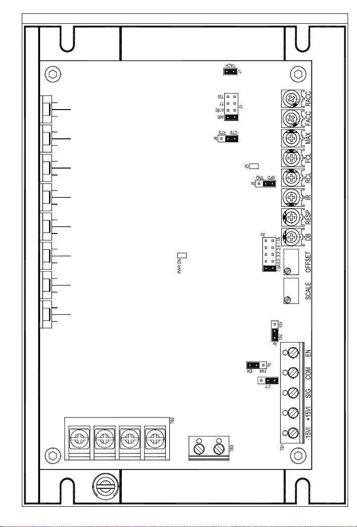
FIGURE 1 B CONTROL LAYOUT
10
M1M2L1 L2
F-F+
Page 11
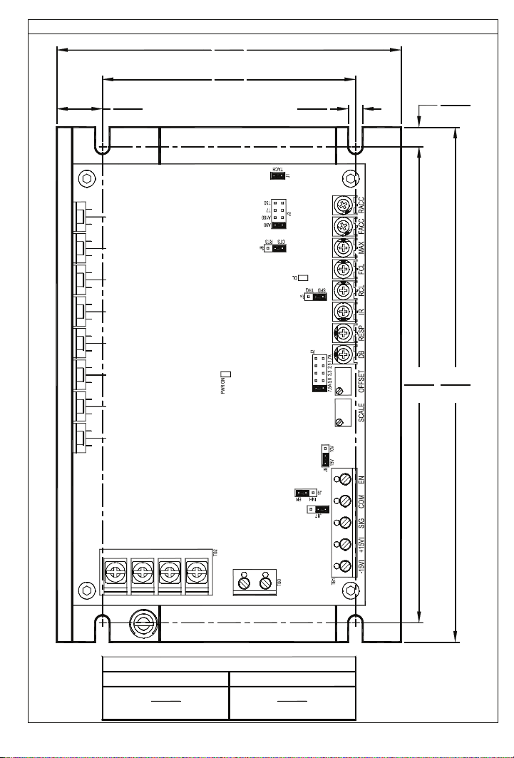
FIGURE 2 B MECHANICAL SPECIFICATIONS (Inches / [mm])
4.75
[120]
3.50
[88.9]
0.625
[15.9]
0.20
[5.08]
6.50
[165]
0.25
[6.35]
7.00
[178]
M1L1 L2 M2
MAXIMUM HEIGHTS
Without Accessory Boards
1.70
[43.2]
F+ F-
With Accessory Boards
3.10
[78.7]
11
Page 12

4 IMPORTANT APPLICATION INFORMATION
AN EXPLOSION CAN CAUSE SERIOUS OR FATAL INJURY. THIS DRIVE IS NOT
WARNING! DO NOT USE THIS DRIVE IN AN EXPLOSIVE ENVIRONMENT.
EXPLOSION PROOF.
WARNING! BE SURE TO FOLLOW ALL INSTRUCTIONS CAREFULLY.
FIRE OR ELECTROCUTION CAN RESULT DUE TO IMPROPER USE OF THIS
PRODUCT. READ SAFETY WARNING ON PAGE 5.
4.1 Motor Type – The KBRG-212D is full-wave regenerative control, capable of
operating a DC motor (Permanent Magnet (PM), or Shunt), in a Bi-Directional mode.
Be sure the drive is used within its stated specifications.
4.2 Torque Requirements – When replacing an AC induction motor with a DC motor
and speed control, consideration must be given to the maximum torque
requirements. The full load torque rating of the DC motor must be equal to, or
greater than, that of the AC motor.
4.3 Acceleration Start – The KBRG-212D contains an adjustable acceleration
start feature that allows the motor to smoothly accelerate from 0-full speed over a
time period of 0.5 to 15 seconds.
4.4 Limitation in Use – The KBRG-212D controls are designed for use on
machine applications.
CAUTION!
- Do not use in explosive atmosphere. Be sure the KBRG-212D is
used within its maximum ratings. Follow all installation instructions carefully (Refer to
Sections 4 and 5).
5 MOUNTING INSTRUCTIONS
Mount the KBRG-212D on a flat surface free of moisture, metal chips, or corrosive
atmosphere. Refer to Figure 2, on page 11.
A 5kΩ ohm remote potentiometer is provided. Install the potentiometer using hardware
provided. Be sure to install insulating disk between potentiometer and inside of front panel.
Enclosure – When mounting the KBRG-212D in an enclosure, it must be large enough to
allow for proper heat dissipation. A 12” x 12” x 24” enclosure is suitable for the KBRG-212D at
full rating. Smaller enclosures may be used if full rating is not required.
12
Page 13

6 ELECTRICAL CONNECTIONS
CONTROL.
WARNING! READ SAFETY WARNING, ON PAGE 5, BEFORE USING THIS
CAUTION! To avoid erratic operation, do not bundle AC line and motor connections
with potentiometer connections, voltage following connections, Start/Stop switch
connections, inhibit connections, or any other signal connections. Use shielded
cables on all signal connections over 12” (30 cm) long. Shield should be earth
grounded on the control
Connect control in accordance with National Electric Code requirements and other local
codes that apply. The KBRG-212D does not contain AC line or armature fusing. It is
recommended that a 20 Amp fuse or circuit breaker be installed on each AC line
conductor not at ground potential. Connect control, in accordance with illustrations in this
section. A separate AC line switch or contactor must be connected as a disconnect switch
so that contacts open each ungrounded conductor. In addition, Table 6, details the
connection, wiring and torque information.
TABLE 6 – TERMINAL BLOCK WIRING INFORMATION
Terminal Block
6.1 AC Line Connection – Connect the AC line to L1 and L2 terminals of TB1 as
6.2 Motor Armature – Connect motor armature to terminal Ml and M2. (Be sure
Designation
TB1
TB2 L1, L2, M1, M2 18 12 3.5
TB3
shown in Figure 3, on page 14.
Note: There are no AC Line or Armature fuses supplied with this control. See Section
6.3, on page 14.
jumper J3 is set to match motor voltage. See Figure 3, on page 14 and Section
7.2, on page 20.
side only.
Connection
Designation
Power / Control
Connections
Supply Wire Gauge
(AWG – Copper)
Minimum
22
F+, F- 22 14 3.5
Maximum
14
Maximum
Tightening
Torque
(lbs- in)
3.5
13
Page 14
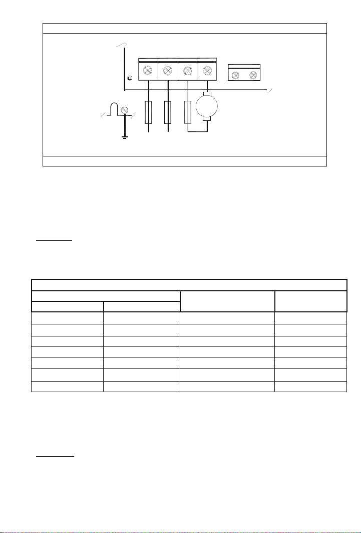
FIGURE 3 – AC LINE AND ARMATURE CONNECTION
TB2
L1 L2 M2 M1
GND
(EARTH)
FUSE
FUSE
AC LINE
+
M
-
FUSE
ARMATURE
INPUT
See Table 6, for Torque Requirements.
TB3
F+ F-
6.3 Fusing
AC Line Fuse – The KBRG-212D does not contain an AC line fuse or Armature
fuse. It is recommended that a 20 Amp fuse or circuit breaker be installed on
each AC line conductor not at ground potential. In addition, refer to Table 7, for
recommended Armature Fusing.
CAUTION: Most electrical codes require that each ungrounded conductor contain
fusing. Separate branch circuit fusing may be required. Check local electrical codes.
6.4 Motor Armature – Connect motor armature to terminals M1 and M2. Be sure that
jumper J2 matches the motor being used. (See Figure 3).
TABLE 7 – ARMATURE FUSE CHART
Motor Horsepower
90 VDC 180 VDC
1/8
¼
Approx. DC Motor
Current Amps
1.3 2
1/6 1/3 1.7
Fuse Rating
(AC Amps)
2
½
¼ ½ 2.5 4
1/3 ¾ 3.3 5
½ 1 5.0 8
¾
1 2 10.0 20
1 ½
7.5 12
6.5 Field (For Shunt Wound Motors Only) – Connect motor armature leads as above.
Connect full voltage shunt field leads (90 volt motors with 100 volt fields and 180 volt
with 200 volt fields) to F+ and F-. Connect half voltage field leads (90 volt motors
with 50 volt fields and 180 volt motors with 100 volt fields) to F+ and L1. See Table
8, Figures 4 and 5, on page 15, for field connection diagrams.
CAUTION! Shunt-Wound motors may be damaged if field remains connected without
motor rotating for an extended period of time.
Note: Do not connect motor armature leads to F+ and F- terminals. Do not use F+ and F-
terminals for PM motors.
14
Page 15
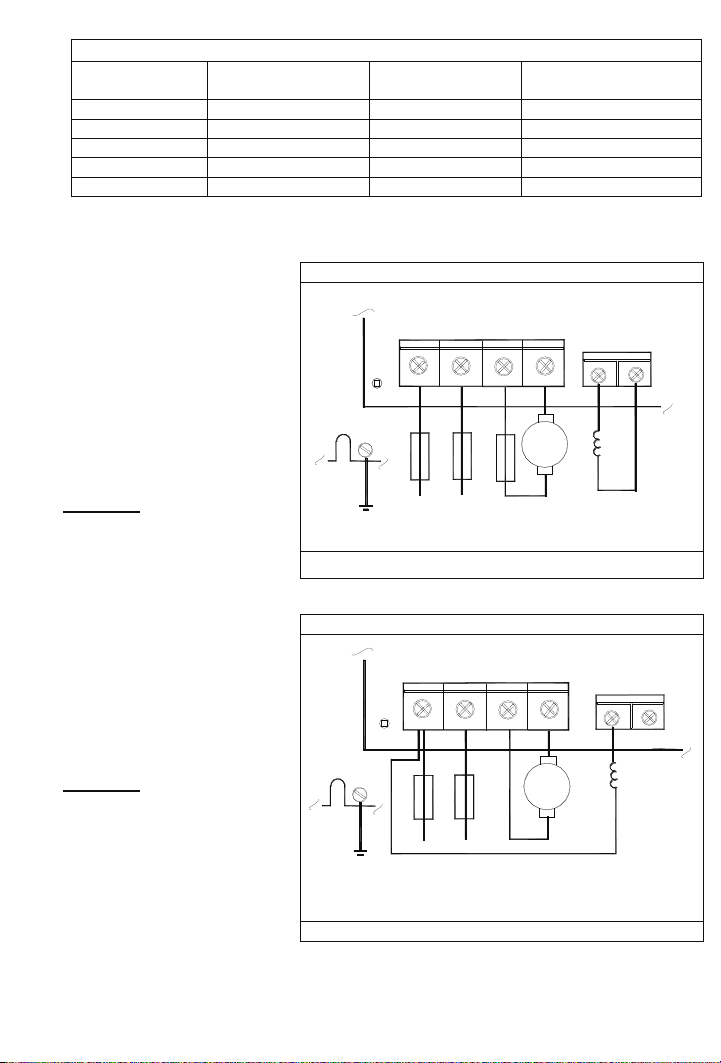
TABLE 8 – FIELD CONNECTIONS (Shunt Wound Motors Only)
AC LINE
VOLTAGE
FIELD VOLTAGE
(VDC)
115 90 100 F+, F115 90 50 F+, L1
230 180 200 F+, F230 180 100 F+, L1
230 *90 100 F+, L1
*Step down operation. See Section 7.2, on page 20.
6.6 Full Voltage Field
Connection (Shunt
FIGURE 4 B FULL VOLTAGE FIELD CONNECTION
Wound Motors Only) –
Connect the motor field
leads to F+ and Fterminals of TB3 as
shown in Figure 4, and
Table 7, on page 14.
Note: Do not connect
motor armature
leads to F+ and
F- terminals.
CAUTION! Do not use F+
and F- terminals of TB3 for
any purpose other than to
power the field of a shunt
wound motor.
6.7 Half Voltage Field
Connection (Shunt
FIGURE 5 B HALF VOLTAGE FIELD CONNECTION
Wound Motors Only) –
Connect the motor field
leads to F+, TB3 and L1
terminals of TB2, as
shown in Figure 5, and
Table 7, on page 14.
CAUTION!
TB3 terminals are
not isolated from AC line. Do
not ground (earth).
Note: Do not connect
motor armature
leads to F+ and
F- terminals.
FIELD VOLTAGE
(VDC)
FIELD CONNECTION
TB2
L1 L2 M2 M1
GND
(EARTH)
FUSE
FUSE
AC LINE
ARMATURE
FUSE
F+ F-
+
M
-
INPUT
See Table 6, for Torque Requirements.
TB2
L1 L2 M2 M1
GND
(EARTH)
FUSE
FUSE
AC LINE
+
-
ARMATURE
F+ F-
M
INPUT
See Table 6, for Torque Requirements.
TB3
FIELD
TB3
FIELD
15
Page 16

6.8 Main Speed Potentiometer Connection – The main speed potentiometer can be
connected in several ways. (A 5kΩ ohm potentiometer is supplied with control. A 10K
potentiometer can also be used.) See Figures 6A – 6D.
6.8.1 Unidirectional operation (FORWARD) – Connect potentiometer to terminals
“+15,” “SIG,” “COM” for forward direction as per Figure 6A.
6.8.2 Unidirectional operation (REVERSE) – Connect potentiometer to terminals
“-15,” “SIG,” “COM” for reverse direction. As per Figure 6B.
6.8.3 Bidirectional operation using reversing contacts – Connect potentiometer
to terminals “-15,” “+15”, “SIG,” “COM” as per Figure 6C.
6.8.4 Bidirectional operation with potentiometer – Connect potentiometer to
terminals “-15,” “+15” “SIG” as per Figure 6D.
FIGURE 6A – UNIDIRECTIONAL
OPERATION (Forward)
FIGURE 6B – UNIDIRECTIONAL
OPERATION (Reverse)
TB1
-15 +15 SIG COM
*
Main Speed Potentiometer
FIGURE 6C – BIDIRECTIONAL
OPERATION (Reversing Contact)
Main Speed Potentiometer
FIGURE 6D – BIDIRECTIONAL with
TB1
-15 +15 SIG COM
POTENTIOMETER
TB1
TB1
-15 +15 SIG
-15 +15 SIG COM
*
*
Main Speed Potentiometer
Notes: 1. * Indicates increase in motor speed. 2. A connection must be made between
EN and COM terminals (TB1) to operate when J9 is in the EN position.
FWD / REV
SWITCH
Main Speed Potentiometer
Center Pot Position = 0 Speed
CW = Full Forward
CCW = Full Reverse
See Table 6, for Torque Requirements.
*
16
Page 17
6.9 Signal Following – In this mode, a signal source is used to vary motor speed.
6.9.1 Voltage Following – Uses a voltage source to vary motor speed. Set J17
In addition, the control is used to isolate, amplify, and condition DC voltage
FIGURE 7A – VOLTAGE FOLLOWING
(See Section 7.7 on page 22 for jumper information) to “VOLT” position and
connect the voltage source to TB1 terminals SIG (+) and COM (-) (See
Figures 7A below and 7C, on page 18), Voltage Following Connection. Be
sure the positive (+) signal is connected to “SIG” terminal and the negative
(-) is connected to the “COM” terminal. When a 0V DC signal is applied, the
motor will operate at the minimum set speed (set by the MIN Trimpot). When
a 10V DC signal is applied, the motor will operate at the maximum set speed
(set by the MAX Trimpot).
6.9.2 Current Following – Uses a current source to vary motor speed. Set J17
(See Section 7.7 on page 22 for jumper information) to “CUR” position and
connect the current source to TB1 terminals SIG (+) and COM (-). See
Figures 7B below, and 7D, on page 18.
signals from any external source (power supplies, motors, tachometer
generators, transducers, and potentiometers). Also provides isolation for
motor direction, switching and an isolated power supply for transducer or
potentiometer operation. See Section 7.7, on page 22.
(DEFAULT)
TB1
FIGURE 7B – CURRENT FOLLOWING
TB1
SIG (+) COM (-)
~
±10 VDC
J17
VOLT CUR
See Table 6, for Torque Requirements.
Notes:
1. Jumper J8 must be in the “10V” position.
2. A positive signal with respect to the COM terminal will produce a positive
output to motor. A negative signal with respect to the COM terminal will
produce a negative output. A 0 to ±10VDC is required to operate control
from 0 to ± full output. Jumper J8 must be set to the 10V position.
SIG (+) COM (-)
4 - 20mA
J17
VOLT CUR
17
Page 18

FIGURE 7C - J17
VOLTAGE SCALE
FIGURE 7D - J8
CURRENT SCALE
90V /
J17
90V /
J17
180 V
0
10
15
4
20mA
6.10 Enable / Inhibit –
be electronically stopped and started with the Enable / Inhibit circuit.
The control features an Enable / Inhibit function. The control can
The Enable circuit functions opposite to that of the inhibit circuit. Inhibit: open to start,
close to stop. Enable: open to stop, close to start.
6.10.1
Enable Mode, EN (212D) – In the Enable mode (Default) connect COM
terminal to the EN terminal via a switch. See Figure 8A.
6.10.1 Inhibit Mode, INH (213D) – When COM terminal and EN terminal are open,
control is in “INHIBIT” state. See Figure 8B.
and the EN terminals or control will not operate. See SAFETY WARNING, on page 5.
FIGURE 8A– ENABLE MODE
(CLOSE TO RUN)
TB1
FIGURE 8B – INHIBIT MODE
(CLOSE TO STOP)
TB1
18
COM EN
SWITCH
INH EN
JUMPER J9
COM EN
INH EN
JUMPER J9
JUMPER
Page 19

6.11 Tach-Generator Feedback, J1 – The KBRG-212D is
factory set for armature feedback which provides good
load regulation for most applications. For superior
load regulation analog tach-generator feedback can
be used.
FIGURE 9 –
J1 -TACH-GENERATOR
FEEDBACK
+ -
J
1
Connect the tach-generator to J1, so that the polarity
of the tach-generator is the same with respect to the
input signal polarity.
Note: If tach-generator is wired for reverse polarity,
the motor will run at full speed. See Figure 9.
7 SETTING SELECTABLE JUMPERS
G
+ -
The KBRG-212D has customer selectable jumpers which must be set before the control
can be used. See Figure 1, on page 10 for jumper locations.
7.1 J2 – Armature Current – Select the J2 position (1.7, 2.5, 3.3, 5, 7.5) closest to the
rated motor current. See Figure 10 and Table 9.
Note: The maximum output current is set to 150% of the J2 position, which may be reset
using the FCL and RCL Trimpots. See Section 10.3, on page 26.
TABLE 9 –
MOTOR HORSEPOWER
J2 Position
Motor
Current
90 VDC 180 VDC
FIGURE 10 - J2 – ARMATURE
CURRENT JUMPER
(SHOWN IN FACTORY SETTING)
J2
(DC Amps)
7.5A 3/4
5.0A 1/2 1
3.3A 1/3 3/4
2.5A 1/4 1/2
1.7A 1/6 1/3
1
½
7.5A
2.5A
1.7A3.3A5.0A
19
Page 20

(
)
7.2 J3 – Armature Voltage
Output and Tach-Generator
Feedback –
Select the
desired armature voltage by
placing J3 in the proper
position, “A90" or
See Figure 11A.
“A180.”
FIGURE 11A – J3
ARMATURE VOLTAGE
(90V)
FIGURE 11B – J3
ARMATURE VOLTAGE
(180V)
(Default Position)
Note: For 115 volt AC
line input, J3 must be
set to “A90.”
For 230
input, the armature
voltage is normally
set for “A180.” However, it is also possible to set the armature voltage to “A90" for
stepdown operation.
7.2.1 Tach-Generator Feedback (for use with 1800 RPM motors.) – Jumper J3 is also
used if tach-generator feedback is to be used. If a 7 volt per 1000 RPM tachgenerator is used, set jumper J3 in the “T7" position. For a 50 volt per 1000 RPM
Note: When using tach-generator feedback, the
IR Comp Trimpot (See Section 10.4, on
page 27) should be turned to a
minimum setting (full CCW). See
Figure 9, and Section 6.11, on page 19.
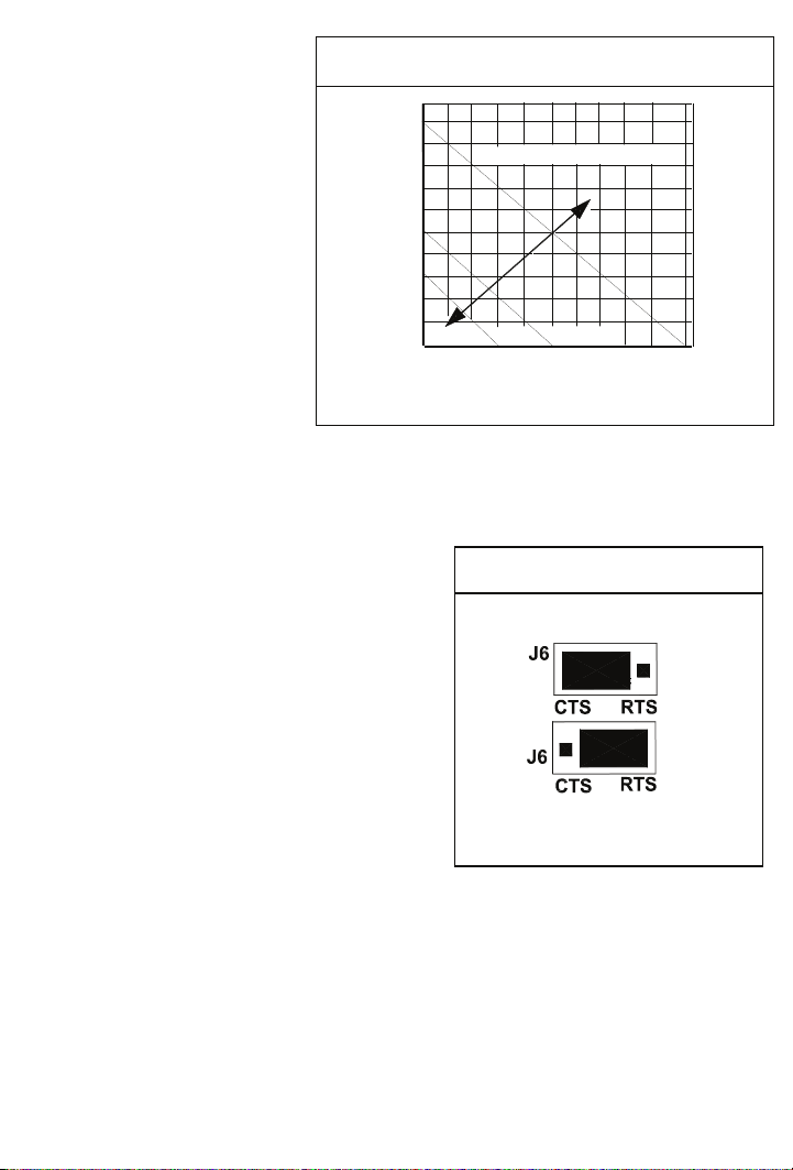
7.3 J5 - Speed (SPD) or Torque (TRQ).
tach-generator, set the jumper in the “T50" position. See Figure 11B.
FIGURE 12 – J5
SPEED / TORQUE (SPD or TRQ)
Default Position
Note: Factory setting of J5 is Speed
mode (Default).
In the speed control mode (J5 set to SPD), the
KBRG-212D will provide variable speed
control. The motor speed will be in direct
proportion to the input signal. Both forward and
reverse torque is used to stabilize motor
Shown in the Torque Mode
speed.
See Figures 12, 13 and 14.
FIGURE 13 – SPEED MODE vs. MOTOR LOAD
100
HIGHER SET SPEED
90
80
70
60
50
40
30
MOTOR SPEED (%)
20
10
LOWER SET SPEED
0
0 10 20 30 40 50 60 70 80 90 100 110 120 130 140 150
APPLIED TORQUE
CL SETPOINT
20
Page 21
In the torque control mode
A
)
(J5 set to TRQ), the
KBRG-212D will vary the
FIGURE 14 - MOTOR SPEED vs.
PPLIED MOTOR LOAD (TORQUE MODE
maximum motor torque as
a function of the voltage
input to terminals “SIG”
(signal) and “COM”
(common). This voltage
can be derived from the
wiper of the main
potentiometer or from an
analog input (voltage
following). If the motor
torque is greater than the
load torque, the motor will
rotate. If no load is
applied to the motor, the
motor will rotate at a
speed proportional to the
100
90
80
HIGHER TORQUE SETTING
70
60
50
40
30
MOTOR SPEED (%)
20
10
LOWER TORQUE SETTING
0
0 10 20 30 40 50 60 70 80 90 100
APPLIED MOTOR LOAD (%) TORQUE
torque setting as set by
the main potentiometer (See Figure 13, on page 21). By using the FACC and RACC
Trimpots, the application of torque can be made more gradual or less gradual as
required by the application. A maximum torque can be established using the current
selector jumper, J2, which can be further modified by using the FCL and RCL Trimpots.
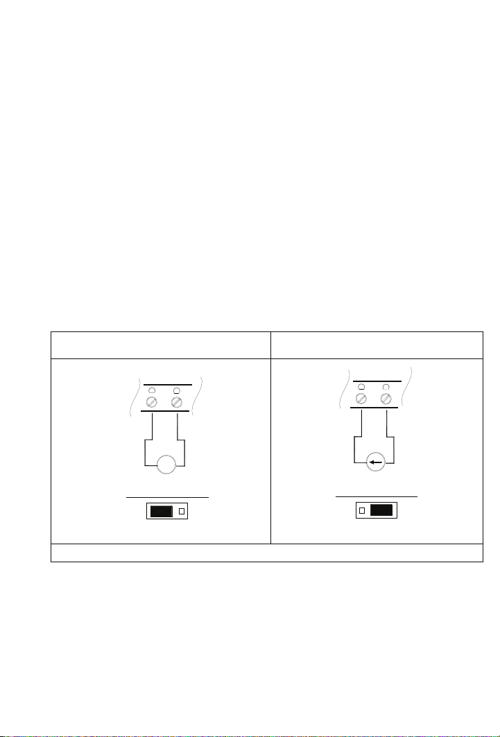
7.4 J6 – Coast to Stop (CTS) Regenerate to
Stop (RTS)
- This function operates in
conjunction with the Enable circuit, which is
used to start and stop the control
electronically. If the circuit connecting
FIGURE 15 – J6
CTS / RTS JUMPER
(Coast to Stop)
terminals “EN” and “COM” on terminal block
TB1 is opened, the control will cause the
motor to stop. When jumper J6 is in the
factory position (
RTS), the motor will
regenerate to a stop. The stop time is
controlled by the Forward Acceleration
(FACC) and Reverse Acceleration (RACC)
Trimpots. If J6 is changed to the coast to stop
(CTS) position, the motor will coast to a stop
when the “EN” - “COM” circuit is opened. See
Figure 15.
(Regenerate to Stop)
Shown in the Default Position
Note: Control will not run unless a jumper or closed contact is connected between the
“EN” and “COM” terminals.
21
Page 22

7.5 J8 – Analog (Signal) Input Voltage –
The output of this control is normally controlled
with the main potentiometer. However, an
analog voltage (isolated) may also be used in
place of a potentiometer. The control can be
scaled for 0 – 10VDC by placing J8 in the
appropriate position "15V" or "10V". The scaling
can be further adjusted with the SCALE Trimpot.
Refer to Section 6.9, (Signal Following) on page
17, and Figure 16, for additional information.
7.6 J17 – Analog Signal Input – J17 is used in
conjunction with jumper J8 and the Main
Speed Potentiometer for, the input of a voltage
or a voltage or current signal
6.9, (Signal Following) on page 17 and Figures
17A and 17B.
“VOLTAGE POSITION (DEFAULT)”
FIGURE 17A - J17
ANALOG SIGNAL INPUT
. Refer to Section
FIGURE 16 - J8 15V / 10V
(Shown in the 10V Position)
JUMPER
J8
15V
10V
J8
15V
(Shown in the 15V Position)
Default Position
FIGURE 17B - J17
ANALOG SIGNAL INPUT
“CURRENT POSITION”
10V
J17
VOLT CUR
7.7
J9 – Enable (EN) / Inhibit (INH) – The control
can be electronically stopped or started with the
inhibit circuit, depending upon the position of
Jumper, J9. The control can also be started and
stopped with the Enable (Factory Set) function.
(The enable circuit functions opposite to that of
the inhibit circuit). See Figure 18 and Section
6.10, on page 18, for wiring information.
22
J17
VOLT CUR
FIGURE 18 - J9 ENABLE /
INHIBIT JUMPER
(Shown in the Enable Position)
INH
EN
J9
INH
EN
J9
(Shown in the Inhibit Position)
Page 23

8 RECOMMENDED HIGH VOLTAGE DIELECTRIC WITHSTAND TESTING
(HI-POT TESTING)
WARNING! READ SAFETY WARNING ON PAGE 5 BEFORE ATTEMPTING
TO OPERATE. SEVERE INJURY OR DEATH CAN RESULT.
Testing agencies such as UL, CSA, etc., usually require that equipment undergo a hi-pot
test. In order to prevent catastrophic damage to the drive, which has been installed in the
equipment, the following procedure is recommended. A typical hi-pot test setup is shown in
Figure 19, on page 24.
requirements.
All drives have been factory hi-pot tested in accordance with UL
WARNING! ALL EQUIPMENT AC LINE INPUTS MUST BE DISCONNECTED
FROM THE AC POWER.
lead of the Hi-Pot Tester. Connect the RETURN of the Hi-Pot Tester to the frame on
which the drive and other auxiliary equipment are mounted.
8.2 The Hi-Pot Tester must have an automatic ramp-up to the test voltage and an
automatic ramp-down to zero voltage.
be manually increased to the test voltage and then manually reduced to zero. This
procedure must be followed for each machine being tested. A suggested Hi-Pot
Tester is Slaughter Model 2550.
CAUTION! Instantly applying the hi-pot voltage will cause irreversible damage to the
drive, which will void the warranty.
23
Page 24

FIGURE 19 - TYPICAL HI-POT TEST SETUP
HIGH VOLTAGE DIELECTRIC WITHSTAND TESTER
(HI-POT TESTER)
LEAKAGE
0mA 10mA
0
12
3
RETURN
AUX. EQUPT.
TEST
H. V. RESET
MOTOR SPEED CONTROL
VOLTAGE
ZERO
MAX
FRAME
9 DRIVE OPERATION
WARNING! READ SAFETY WARNING ON PAGE 5 BEFORE ATTEMPTING TO
OPERATE OR SEVERE INJURY OR DEATH CAN RESULT.
The input voltage can be derived from the wiper of the Main Speed Potentiometer or from an
analog input (voltage following mode). Since the KBRG-212D is a 4-quadrant regenerative
drives, the motor speed will follow both a positive and negative wiper voltage and drive the
motor in both the forward direction and reverse direction. In addition, it will apply both forward
and reverse torque in order to stabilize motor speed.
Example: To understand the concept of a regenerative drive, the operation of an elevator can
be used. If one were to enter the elevator on the first floor and press 10, the motor and control
would have to lift the elevator against gravity. In this mode, the drive would operate like a
conventional speed control which is called "motoring" (the applied load is opposite to the
direction of motor speed).
When the elevator is at floor 10 and floor 1 is pressed, gravity will try to pull the elevator car
down faster than the speed for which it is set. The control will then provide reverse torque to
keep the car form falling faster than the set speed. This operation is regeneration (the applied
load is in the same direction as the direction of motor rotation). Table 10, on page 25
summarizes the different modes of regen operation.
24
Page 25

The KBRG-212D can be operated as speed controls or torque controls by setting the
position of jumper J5. The Main Speed Potentiometer controls the magnitude of the mode
selected. Set jumper J5 to "SPD" for speed control or to "TRQ" for torque control. See
Table 10.
10 TRIMPOT ADJUSTMENTS
The KBRG-212D contains trimpots, which are factory set for most applications. Figure 1, on
page 10, illustrates the location of the trimpots and their approximate calibrated positions.
Some applications may require readjustment of the trimpots in order to tailor the control for a
specific requirement. Readjust trimpots as described below.
TABLE 10 – SUMMARY OF CONTROL (REGEN) OPERATION
Quadrant
I Motoring CW CW CCW
II Regeneration CCW CW CCW
III Motoring CCW CCW CW
IV Regeneration CW CCW CW
Type of
Operation
Motor
Rotation
Direction
Motor
Torque
Direction
Applied
Load
Direction
APPLIED. IF ADJUSTMENTS ARE MADE WITH MAIN POWER APPLIED, AN
INSULATED KB ADJUSTMENT TOOL MUST BE USED AND SAFETY GLASSES MUST
BE WORN. HIGH VOLTAGE EXISTS IN THIS CONTROL. FIRE AND/OR
ELECTROCUTION CAN RESULT IF CAUTION IS NOT EXERCISED. SAFETY
WARNING, ON PAGE 5, MUST BE READ AND UNDERSTOOD BEFORE PROCEEDING.
10.1 Forward Acceleration (FACC) and Reverse Acceleration (RACC)
The RACC Trimpot determines the amount of time it takes the control voltage to
The FACC and RACC Trimpots are factory set to 1 second. The acceleration times
Notes:
WARNING! IF POSSIBLE, DO NOT ADJUST TRIMPOTS WITH MAIN POWER
Trimpot determines the amount of time it takes the control voltage to reach full output
in the forward direction. It also determines the amount of time it takes for the control
voltage, in the reverse direction, to reach zero output (FACC is the Reverse Decel)
See Figure 20A, on page 26.
reach full output in the reverse direction. It also determines the amount of time it takes
the control voltage, in the forward direction, to reach zero output to decelerate in the
reverse direction (FACC = Reverse Deceleration).
are adjustable to a maximum of 15 seconds (RACC is the forward Decel) See Figure
20B, on page 26.
The FCL and RCL Trimpot settings may override the rapid accel and decel
settings.
– The FACC
25
Page 26
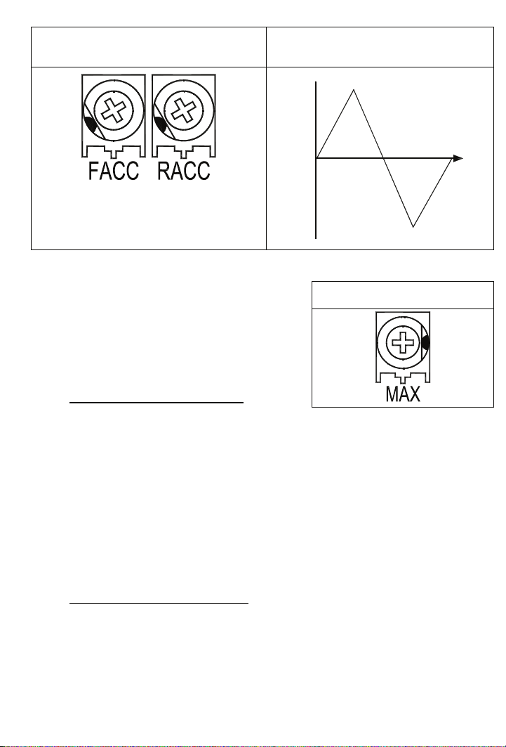
FIGURE 20A –
FORWARD AND REVERSE
ACCELERATION TRIMPOT POSITIONS
FIGURE 20B – ACCEL TRIMPOT
ADJUSTMENT
100
0
Speed (%)
L
R
E
C
E
V
C
A
A
D
W
F
C
C
E
L
R
E
V
A
C
C
E
L
W
F
Time
C
A
D
L
E
C
-100
10.2 Maximum Speed (MAX) - The MAX Trimpot is
used to set the maximum output voltage of the
control which, in turn, sets the maximum speed
FIGURE 21 –MAXIMUM SPEED
TRIMPOT POSITION
of the motor. The MAX Trimpot is factory
setto100% of base speed. In the Torque
Control Mode, the MAX Trimpot setting
determines the unloaded motor speed. See
Figure 21.
Adjust the MAX Trimpot as follows:
a. Rotate Main Speed Potentiometer to full speed (CW).
b. Adjust MAX trimpot to desired maximum motor speed.
Note: Do not exceed maximum rated RPM of motor since unstable operation may
result.
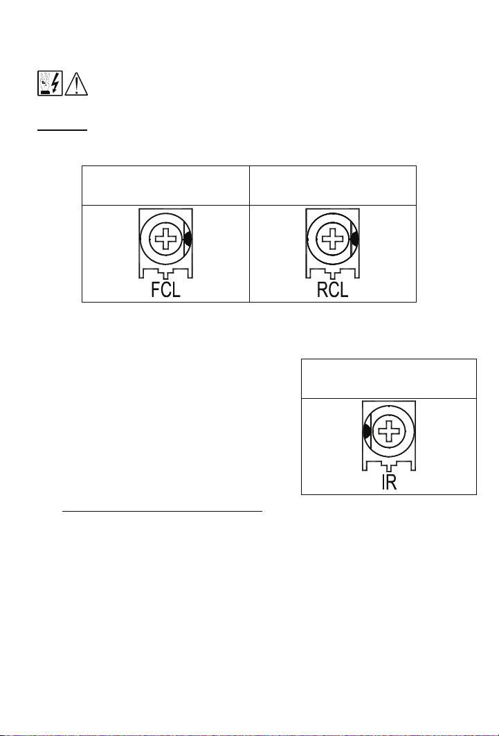
10.3 Forward Current Limit (FCL) and Reverse Current Limit (RCL) Trimpots - These
trimpots are used to set the maximum amount of DC current that the motor can draw in
both the forward and reverse directions. The amount of DC current determines the
amount of maximum motor torque in both the Speed Control Mode and Torque Control
Mode. They are factory set to 150% of the current established by the jumper J2
position. See Figures 22A and 22B, on page 27.
Readjust the CL trimpots as follows:
a. Turn CL trimpot to MIN (CCW) position. Be sure jumper J2 is in proper position
approximately equal to the motor DC ampere rating.
b. Connect a DC ammeter in series with armature lead. Lock shaft of motor.
26
Page 27
c. Apply power; Rotate CL trimpot CW until desired CL setting is reached (factory
setting is 1.5 times rated motor current). Be sure control is in Forward direction for
FCL trimpot adjustment and likewise with RCL.
SECONDS, TO PREVENT MOTOR DAMAGE.
CAUTION: Adjusting the CL above 150% of motor rating can cause overheating and
demagnetization of some PM motors. Consult motor manufacturer.
WARNING! DO NOT LEAVE MOTOR SHAFT LOCKED FOR MORE THAN 2 - 3
FIGURE 22A – FORWARD
CURRENT LIMIT TRIMPOT
POSITION
FIGURE 22B – REVERSE
CURRENT LIMIT TRIMPOT
POSITION
10.4 IR Compensation (IR Comp)
used to stabilize motor speed under varying
loads. The IR Trimpot is factory set to 5 Volts
DC, with 115 Volt AC line input, and 10 Volts
- The IR Comp is
FIGURE 23 – IR
COMPENSATION TRIMPOT
POSITION
DC, with 208/230 Volt AC line input. See
Figure 23.
If control is in Tach Feedback mode, the IR
Comp should be set to minimum -CCW.
Note: Too much IR Comp will cause unstable
(oscillatory) operation.
Readjust the IR Comp trimpot as follows:
a. Run motor at approximately 30-50% of rated speed under no load and measure
actual speed.
b. Load motor to rated current. Rotate IR Comp trimpot so that loaded speed is the
same as the unloaded speed measured in the previous step.
Control is now compensated so that minimal speed change will occur over a wide range
of motor load.
27
Page 28

10.5 Response (RESP) - This trimpot determines the
dynamic response of the control. The factory
setting is approximately 50% of full rotation. The
setting may be increased if a faster response is
required. See Figure 24.
Note: If response is made too fast, unstable
operation may result.
10.6 Deadband (DB) - The DB trimpot sets the amount
of Main Speed Potentiometer rotation required to
initiate control voltage output. The DB Trimpot is
factory set to 0%. See Figures 25A and 25B.
FIGURE 25A –
DEADBAND TRIMPOT
POSITION
DEADBAND TRIMPOT ADJUSTMENT
FIGURE 24 –RESPONSE
TRIMPOT POSITION
FIGURE 25B –
100
(%) SPEED
-100
b
a
-100
Curve (a): No Deadband
Curve (b): Max. Deadband
a
b
100
The DB trimpot also determines the amount of delay that will occur before regeneration
starts. (Regeneration occurs when the applied load torque is in the same direction as the
motor rotation).
To readjust the DB to factory setting:
a. Set Main Speed pot to zero speed position.
b. Set DB trimpot to full CCW position.
c. Adjust DB trimpot CW until motor hum is eliminated.
Note: If the deadband trimpot is set too low (CCW direction), the motor may oscillate
between forward and reverse. Adjust deadband trimpot CW until the instability
disappears. (Oscillation may also occur due to response setting). See Sections
10.5 and 10.6.
28
Page 29

10.7 Offset (OFFSET) - This trimpot determines the amount of bias in the forward or reverse
direction. The trimpot is factory set to provide approximately zero offset, which means
neither the forward nor the reverse speed is favored. See Figures 26A and 26B.
FIGURE 26A –
OFFSET TRIMPOT POSITION
OFFSET TRIMPOT ADJUSTMENT
FIGURE 26B –
100
(%) SPEED
-100
b
(%)
a
c
100
MAIN SPEED
POT
ROTATION
-100
CURVE OFFSET
(a) None (b) Forward (c) Reverse
10.8 Scale (SCALE) – The Scale potentiometer is used in conjunction with jumper J8
(Section 7.5, on page 22) and the MAX Trimpot (Section 10.2, on page 26). This allows
for fine adjustments of the analog input signal within the 0 – 10V or 0 – 15V ranges. In
addition, the trimpot has an adjustment range of ±5 to ±25V. See Figures 27A and 27B.
FIGURE 27A –
SCALE TRIMPOT POSITION
Note: Factory setting for this
FIGURE 27B – SCALE TRIMPOT ADJUSTMENT
VOLTS
180/90
Potentiometer will be equivalent to
87 V DC for a 90 V DC motor.
Refer to the example below.
,
5 10 25
INPUT VOLTAGE
Example: Using a 90 V DC motor, and with jumper J8 to the 10V position. Adjust the
Main Speed Potentiometer (Section 6.8, on page 16) to maximum clockwise (CW)
position. At this point, the motor will be running at full speed. Adjust the SCALE trimpot,
3 turns in a counter-clockwise (CCW) position, until the voltmeter reads approximately
87 V DC (Production voltage setup).
29
Page 30

11 DIAGNOSTIC LEDS
The KBRG-212D is designed with LEDs mounted on the Control Board, to indicate the
control=s operational status. See Figure 1, on page 10.
11.1 LED 1 Power On (PWR ON) -Indicates that the drive is energized with the AC line.
11.2 LED 2 Current Overload (OL) - Indicates that the drive is in Current Overload.
12 TROUBLESHOOTING
POWER BEFORE MAKING CONNECTIONS TO THE DRIVE. THE COVER MUST BE
WARNING! HIGH VOLTAGE IS PRESENT IN THIS DRIVE. DISCONNECT MAIN
PROPERLY SECURED, AFTER ALL SETUP CONNECTIONS, AND ADJUSTMENTS ARE
COMPLETE. THIS REDUCES ELECTRICAL SHOCK HAZARD. FAILURE TO OBSERVE
THIS WARNING COULD RESULT IN ELECTRICAL SHOCK OR ELECTROCUTION.
WARNING! HIGH VOLTAGE IS PRESENT IN THE DRIVE. IF POSSIBLE, DO NOT
ADJUST TRIMPOTS WITH THE MAIN POWER APPLIED. IF ADJUSTMENTS ARE MADE
WITH THE MAIN POWER APPLIED, AN INSULATED ADJUSTMENT TOOL (PROVIDED)
MUST BE USED AND SAFETY GLASSES MUST BE WORN. FIRE AND/OR
ELECTROCUTION CAN RESULT IF CAUTION IS NOT EXERCISED.
12.1 TROUBLESHOOTING GUIDE: Table 11, provides information on symptoms, possible
causes, and the suggested troubleshooting solutions for the drive. See Section 11 for
information on LED status indicators.
TABLE 11– TROUBLESHOOTING GUIDE
Indication / Symptom
Possible Solutions
The Main Speed Potentiometer is set to zero
speed. Set the Main Speed Potentiometer
Motor is not running and Power On LED
indicator is illuminated.
for the desired speed.
The Main Speed Potentiometer, signal input,
or motor connections are open. Verify Main
Speed Potentiometer, signal input, or motor
connections.
Power ON LED indicator is not
illuminated.
Check to see if the AC Line connections have
been made.
Check AC Line fuse.
The line fuse or circuit breaker installed is
Line fuse blows or circuit breaker trips.
the incorrect rating. See Table 5, on page 8,
for the correct line fuse or circuit breaker
rating.
Troubleshooting continued on the following page.
30
Page 31

Troubleshooting (Continued)
OL LED indicator is illuminated.
Note: For any other problems, consult the factory representative.
Motor is overloaded. Check motor amps with
DC ammeter in series with armature. (If motor
is shunt type, field may be open or not
receiving proper voltage.)
Check motor for shorts or grounds. Motor
may be defective.
Check position of RCL and FCL trimpots. The
trimpots may be set too low.
Rapid Acceleration change will cause the
LED to illuminate. Verify potentiometer
setting.
31
Page 32

For a period of 18 months from the date of original purchase, KB Electronics, Inc. will repair or
replace without charge, devices which our examination proves to be defective in material or
workmanship. This warranty is valid if the unit has not been tampered with by unauthorized
persons, misused, abused, or improperly installed and has been used in accordance with the
instructions and/or ratings supplied. The foregoing is in lieu of any other warranty or
guarantee, expressed or implied. KB Electronics, Inc. is not responsible for any expense,
including installation and removal, inconvenience, or consequential damage, including injury
to any person, caused by items of our manufacture or sale. Some states do not allow certain
exclusions or limitations found in this warranty and therefore they may not apply to you. In
any event, the total liability of KB Electronics, Inc. under any circumstance shall not exceed
the full purchase price of this product. (rev 2/2000)
COPYRIGHT © 2009 KB Electronics, Inc.
All rights reserved. In accordance with the United States Copyright Act of 1976, no part of
this publication may be reproduced in any form or by any means without permission in writing
from KB Electronics, Inc. (8/2002)
LIMITED WARRANTY
KB Electronics, Inc.
12095 NW 39 Street, Coral Springs, FL 33065-2516
Phone: 954-346-4900; Fax: 954-346-3377, Outside Florida call Toll Free: 800-221-6570
e-mail: info@kbelectronics.com
www.kbelectronics.com
(A40291) – Rev. D00 – 9/10/2009
 Loading...