

KBPC-240D
TM
TM
®
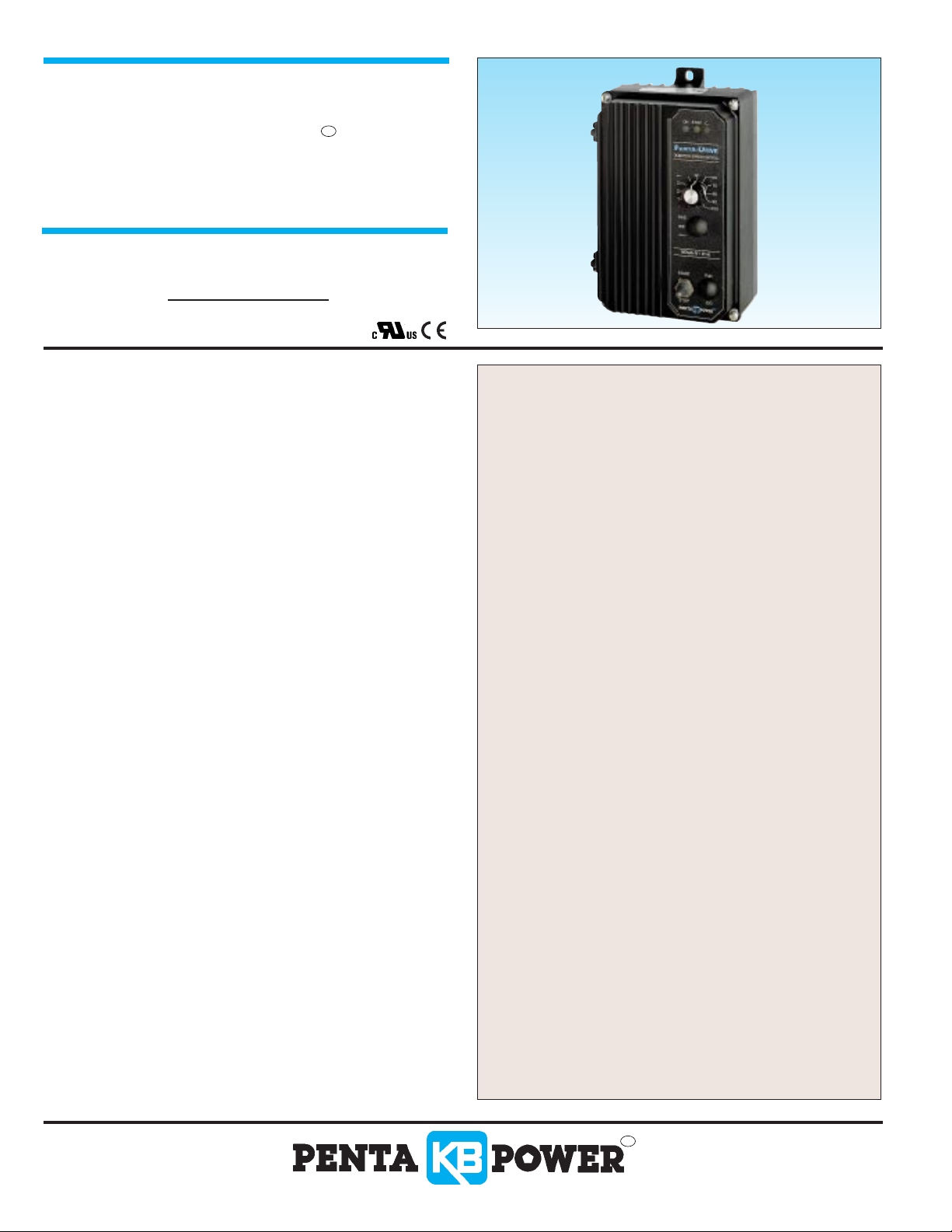
PENTA-DRIVE
NEMA-4X, IP-65
Var iable Speed-Torque SCR DC Motor Control
for Shunt Wound and PM Motors
ONE MODEL COVERS:
1/50 – 1 Hp @ 115 VAC – 50/60 Hz
1/25 – 2 Hp @ 230 VAC – 50/60 Hz
DATA SHEET D-212
Washdown and Watertight
for Indoor and Outdoor Use
STANDARD FEATURES
• Electronic Overload Protection
• Built-in Ar mature Fusing
▲
• LED’s for “Power On,” “Overload” and “Stop”
• Electronic Star t-Stop
▲
Fuse supplied separately
JUMPER SELECTABLE FEATURES
• Control Mode: Speed, Torque
• DC Current Output (ADC): 2.5, 5.0, 7.5, 10
• AC Line Voltage (VAC-50/60 Hz): 115, 230
• DC Armature Voltage (VDC): 90, 180
• Feedback Type: Armature, Tachometer
▲
• Tachometer Voltage
(VDC): 7, 20/30, 50
• Timed Current Limit: TCL, NTCL
Bold figure indicates factory setting.
▲
Per 1,000 RPM
TRIMPOT ADJUSTMENTS
• Minimum Speed (MIN) • Maximum Speed (MAX)
• Current Limit (CL) • IR Compensation (IR)
• Acceleration (ACCEL) • Deceleration (DECEL)
• Timed Current Limit (TCL) • Jog Speed (JOG)
▲
Used with Run-Stop-Jog option.
▲
*
DESCRIPTION
The KBPC Series NEMA-4X (IP-65) SCR DC Motor
Speed and Torque Control is designed for applications
requiring washdown watertight integrity. Its housing is
ruggedly constructed of die cast aluminum which is
protected with an acrylic coating for the ultimate in
corrosion resistance. All switches are sealed with
rubber boots and the main speed potentiometer
contains a shaft seal.
The KBPC state-of-the-art electronics include shor t
circuit and transient protection to provide the ultimate in
reliability. Electronics overload protection is also provided
which prevents motor burnout and demagnetization of
PM motors. The control can be operated in either the
speed or torque mode via a jumper selection. The
current range, which is also jumper selectab le, eliminates
the necessity for calibration of IR compensation and
current limit for most applications. The KBPC also
contains jumper selections for AC line voltage
(230/115), DC armature voltage (180/90) and feedback
type (armature/tachometer).
Standard features include Armature Fusing,
Electronic Start/Stop and LED Indicator Array for
“Power On,” “Stop” and “Overload.”
OPTIONAL FEATURES
• Forward-Brake-Reverse Switch with hesitation feature
(P/N 9339). Includes switch and prewired dynamic brake
resistor.
• Run-Stop-Jog Switch (P/N 9340)
• Signal Isolator, KBSI-240D (P/N 9431)
• On/Off AC Line Switch (P/N 9341)
• White Case (FDA) (P/N 9342)
• Electronic Pot, KBEP-240D (P/N 9108)
• Anti Plug Reversing Module (P/N 9378)
• Auto/Manual Kit (P/N 9377)
* CE Compliance Requires KBRF-200A RFI Filter
40
A Complete Line of Motor Drives
Although the KBPC is factory set for most applications,
a variety of trimpots allows adjustment of the following
parameters: MIN and MAX speed, Acceleration,
Deceleration, Current Limit, IR Comp, and Timed
Current Limit.The drive offers the ultimate in flexibility
with the availability of several customer installed
options. These include: Anti Plug Reversing Module,
Forward-Brake-Reverse with Hesitation Feature, Run
Stop-Jog, On/Off AC Line Switch, Input Signal
Isolation, and Electronic Potentiometer. A complete
instruction manual is included.
Rev.______(A_______)
SPECIFICATIONS
Parameter Specification
AC Line Voltage Regulation (% Base Speed).............. ±0.5 .............. —
Current Ranges (ADC) ........................................ 2.5, 5, 7.5, 10 ...... 10
ACCEL and DECEL Ranges (Seconds) .................... 0.1–15 ............ 1
MIN SPEED Range (% Base Speed) ........................ 0–30 .............. 0
MAX SPEED Range (% Base Speed) ...................... 60–140 .......... 100
IR COMP Range at 115 VAC Line (VDC) .................. 0–15 .............. 4
IR COMP Range at 230 VAC Line (VDC) .................. 0–30 .............. 8
CL Range (% Range Setting) .................................... 0–200............ 150
TIMED CL Range (Seconds) .................................... 0.5–15 ............ 7
Voltage Following Linearity (% Base Speed) .............. ± 0.5.............. —
Factory
Setting
Parameter Specification
Horsepower Range at 115 VAC Line (Hp) [kw].... 1/50–1, [.015-.75].... —
Horsepower Range at 230 VAC Line (Hp) [kw] .... 1/25–2, [.03–1.5] .... —
Armature Voltage Range at 115 VAC Line (VDC) .......... 0–130*............ —
Armature Voltage Range at 230 VAC Line (VDC) .......... 0–220* .......... 180
Field Voltage at 115 VAC Line (VDC) .......................... 100/50** .......... —
Field Voltage at 230 VAC Line (VDC) .......................... 200/100**.......... —
Ambient Temperature Range (°C) .................................. 0–50.............. —
Speed Range (Ratio)........................................................ 50:1.............. —
Load Regulation, Arm. Feedback(% Base Speed) ............ ± 1 .............. —
Load Regulation, Tach. Feedback (% Set Speed).............. ± 1 .............. —
AC Line Voltage (VAC ± 10%, 50/60 Hz)................ 115 or 230 ........ 230
NOTES: *Maximum recommended output voltage is 90 VDC for 115 VAC and 180 VDC for 230 VAC. Exceeding these output voltages may cause a reduction in load
regulation performance.
**For shunt wound motor with lower voltage field, use L1 and F1 connection.
ELECTRICAL RATINGS
Model
Number
KB Part
Number
AC Line Voltage
(VAC) ± 10%
50/60 Hz
9338 (Black)
KBPC-240D
9342 (White)
*Stepdown operation (90 VDC motors with 230 VAC input) can cause a reduction in motor performance.**Shunt motors only
115/230
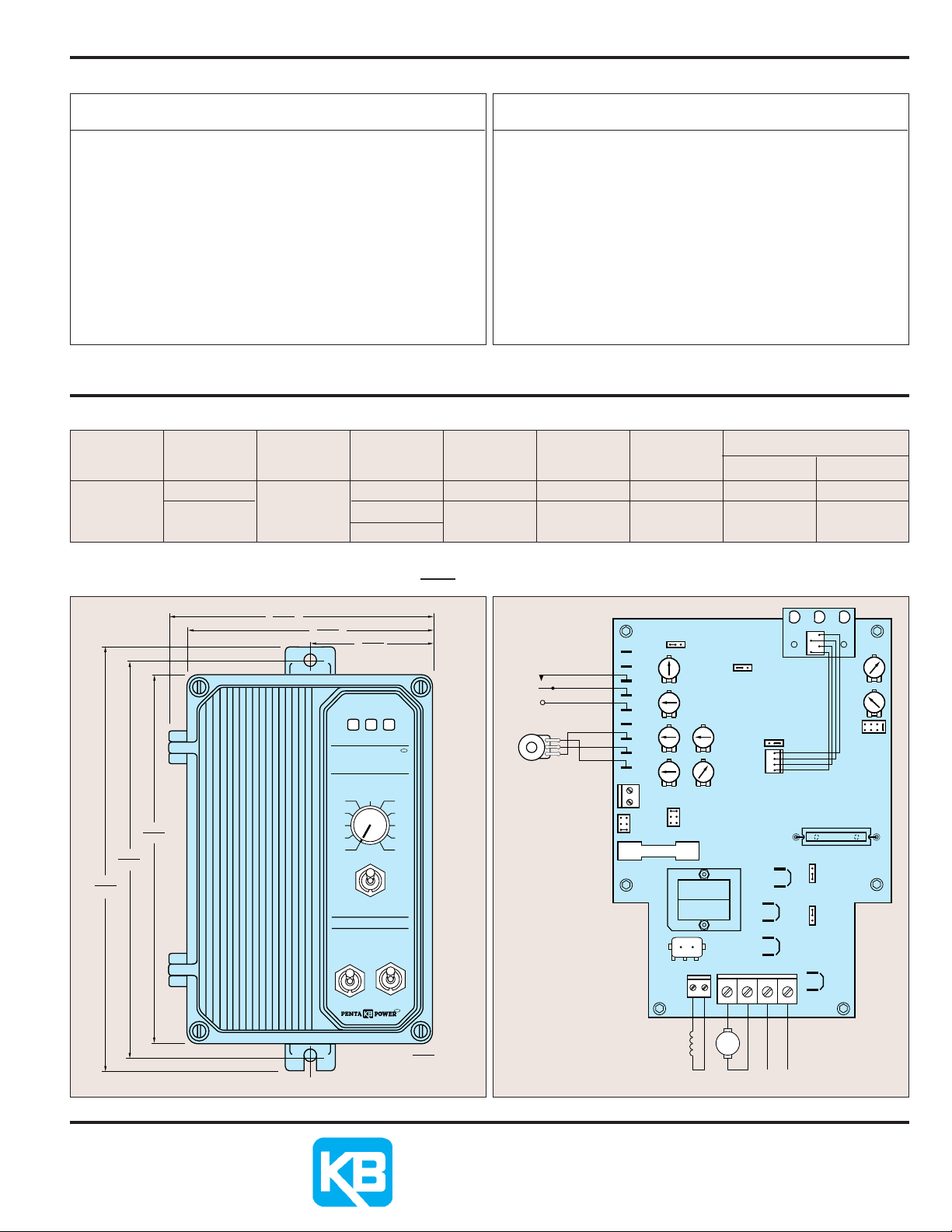
MECHANICAL SPECIFICATIONS CONNECTION DIAGRAM
5.886
9.488
(241.00)
8.875
(225.50)
8.228
(209.00)
(149.50)
_ 0.25" MOUNTING SCREWS
5.472
(139.00)
DC MOTOR SPEED CONTROL
Motor
Voltage
(VDC)
0 – 130
0 – 180
0 – 130*
Max. AC
Load Current
(RMS Amps)
15.0
15.0
Max. DC
Load Current
(DC Amps)
10.2
10.2
Maximum
Horsepower
Hp, (KW)
1, (.75)
2, (1.5)
Field Voltage** (Volts DC)
Terminals F1, F2 Terminals F1, L1
100
200
INCHES
[mm]
TRQ SPD
CONN1
J9A
INPUT
A1B
J8A
A1A
A2B
J8B
A2A
LED BOARD
ON
YGRB
TB1
MAIN BOARD
F1
50V
20/30V
7V
TCL
I1
I2
START
COM
STOP
JOG
P3
P2
P1
T+
T-
ARM FUSE
J5
NTCL
TCL
JOG
DECEL
MIN MAX
180V
90V
T
J3
F1 F2
TB2
FIELD
10V 5V
J7
ACCEL
T1
CONN2
A1 A2 L1 L2
F1
F2
+- +-
M
FIELD (*) ARMATURE AC LINE
J1
L1B
L1A
2.736
(69.50)
ON STOP OL
PENTA-DRIVE
50
40
30
20
10
0
%
FWD
BRK
REV
NEMA-IV / IP-65
START RUN
STOP JOG
MAXIMUM DEPTH
START
STOP
START/STOP SWITCH
TM
MAIN
POTENTIOMETER
60
70
80
90
100
TM
5.000
(127.00)
FIELD CONNECTION USED ON SHUNT MOTORS ONLY.
MOTORS WITH HALF VOLTAGE FIELD USE F1 AND L1.
INHIBIT
WHT
BLK
RED
VLT
ORN
WHT
TB3
TACH INPUT
J6
DWG#: C2800-1-00413 DWG#: B2800-2-00359H
© 1998 KB Electronics, Inc.
J2A
J2B
STOP
115V
230V
230V
115V
50
100
CL
CL
IR
J4
R69
L2A
(2)
J9B
L2B
Factory
Setting
10A
7.5A5A2.54
KB ELECTRONICS, INC.
12095 NW 39th Street, Coral Springs, FL 33065-2516
(954) 346-4900 • FAX (954) 346-3377
Outside Florida Call TOLLFREE (800) 221-6570
www.kbelectronics.com
Rev.______(A_______)
41
 Loading...