


KBIC® |
|
|
SCR |
|
|
DC Motor |
|
|
Speed Controls |
|
|
Ultra Fast |
|
|
CL Circuit Prevents |
|
|
Demagnetization in |
|
|
PM Motors |
|
|
Installation and |
BASIC KBIC |
® |
Operation Manual |
|
|
|
|
|
|
|
* |
See SAFETY WARNING |
|
|
* See CE information on page 5 |
This Manual Covers Models |
|
|
KBIC-120, 125, 240, 225, 240D, 240DS |
|
© 2008 KB Electronics, Inc.
(See back cover)
|
TABLE OF CONTENTS |
|
Section |
Page |
|
1 |
Quick-Start Instructions..................................................................................................................... |
3 |
2 |
Safety ............................................................................................................................................... |
5 |
3 |
Introduction....................................................................................................................................... |
6 |
4 |
Application Information ..................................................................................................................... |
6 |
5 |
Installation, Mounting Instructions and Electrical Connections .......................................................... |
12 |
6 |
Recommended High Voltage Dielectric Withstand Testing (HI-POT) ............................................... |
14 |
7 |
Trimpot Adjustments ......................................................................................................................... |
16 |
8 |
Diagnostic LED’s............................................................................................................................... |
20 |
9 |
Control Functions.............................................................................................................................. |
20 |
10 |
Optional Accessories ........................................................................................................................ |
23 |
Table |
Page |
|
1 |
Field Connections (Shunt-Wound Motors Only) ................................................................................ |
8 |
2 |
Electrical Ratings .............................................................................................................................. |
8 |
3 |
Minimum Supply Wire Size Requirements ........................................................................................ |
9 |
4 |
Fuse Selection Chart ........................................................................................................................ |
9 |
5 |
General Performance Specifications................................................................................................. |
10 |
6 |
Plug-In-Horsepower Resistor Chart .................................................................................................. |
11 |
7 |
RFI Filter Selection ........................................................................................................................... |
24 |
Figure |
Page |
|
1 |
General Connection Diagram............................................................................................................ |
4 |
2 |
Mechanical Specifications................................................................................................................. |
7 |
3 |
HI-POT Test Setup ........................................................................................................................... |
15 |
4 |
ACCEL Trimpot Range ..................................................................................................................... |
16 |
5 |
MIN Trimpot Range........................................................................................................................... |
17 |
6 |
MAX Trimpot Range ......................................................................................................................... |
17 |
7 |
CL Trimpot Range............................................................................................................................. |
18 |
8 |
IR Trimpot Range.............................................................................................................................. |
19 |
9 |
Dynamic Braking............................................................................................................................... |
20 |
10 |
Master / Follower Circuit Connection ................................................................................................ |
21 |
11 |
Connection Methods ......................................................................................................................... |
22 |
12 |
Internal Sensing................................................................................................................................ |
23 |
2 |
|
|

1 QUICK-START INSTRUCTIONS
Important: You must read these simplified instructions before proceeding. These instructions are to be used as a reference only and are not intended to replace the details provided herein. You must read the Safety Warning on, page 5, before proceeding.
See Figure 1, on page 4. Also see Section 3 - Application Information, on pages 6 and 7.
WARNING! Disconnect main power before making connections to the speed control.
1.1Be sure the AC input line voltage corresponds to the control voltage. See Table 2, on page 8.
1.2Install the correct Plug-In Horsepower Resistor® according to armature voltage and motor horsepower. See Table 6, on page 11.
1.3Recheck connections: AC line to L1 and L2, armature to A+ and A- and Field (Shunt motors only) to F+ and F-. (Note: If motor runs in improper direction, interchange armature leads with Main Power disconnected.) See Figure 1, on page 4.
1.4It is recommended that both AC line and armature fuses be installed. See Table 4, on page 9.
3

FIGURE 1. GENERAL CONNECTION DIAGRAM


 (Shunt Motors Only)


4

2SAFETY WARNING
Definition of Safety Warning Symbols


 Electrical Hazard Warning Symbol: Failure to observe this warning could result in electrical shock or electrocution.
 Operational Hazard Warning Symbol: Failure to observe this warning could result in serious injury or death.

 This product should be installed and serviced by a qualified technician, electrician, or electrical maintenance person familiar with its operation and the hazards involved. Proper installation, which includes electrical connections, fusing or other current protection, and grounding, can reduce the chance of electrical shocks, and/or fires, in this product or products used with this product, such as electric motors, switches, coils, solenoids, and/or relays. Do not use this drive in an explosion-proof application. Eye protection must be worn and insulated adjustment tools must be used when working with drive under power. This product is constructed of materials (plastics, metals, carbon, silicon, etc.) which may be a potential hazard. Proper shielding, grounding, and filtering of this product can reduce the emission of radio frequency interference (RFI) which may adversely affect sensitive electronic equipment. It is the responsibility of the equipment manufacturer and individual installer to supply this Safety Warning to the ultimate end user of this product. (SW 1/2006)
This drive contains electronic Start/Stop circuits, which can be used to start and stop the drive. However, these circuits are never to be used as safety disconnects since they are not fail-safe. Use only the AC line for this purpose.
Be sure to read and follow all instructions carefully. Fire and/or electrocution can result due to improper use of this product.


 This product complies with all CE directives pertinent at the time of manufacture. Contact the Sales Department for Declaration of Conformity. Installation of a CE approved RFI filter is required (see Table 7, on page 24). Additional shielded cable and/or AC line cables may be required along with a signal isolator (SI-5 (Part No. 9443)).
5
3INTRODUCTION
Thank you for purchasing the KBIC® "Standard of the Industry" DC motor speed controls. The speed controls are designed for applications demanding good performance, high reliability and low cost. The controls are fabricated with components that have proven reliability, including MOV transient protection, which is used to protect the Power Bridge. Integrated circuitry is used to provide an uncomplicated design with superior load and line voltage regulation. The Direct-Fed™ current limit circuit protects the motor and control against overloads by limiting the maximum level of output current. It also prevents motor failure due to demagnetization of the magnets of PM motors. Acceleration start (adjustable from 0.5 to 4 seconds) provides a smooth start each time the AC power is applied.
A unique feature of the KBIC® control is the Plug-in Horsepower Resistor®. It eliminates the need to recalibrate IR Comp. and CL when the control is used over a wide range of motor horsepower. Additional
versatility is achieved by using the Auxiliary Heat Sink (optional) which is used to double the horsepower rating of each model. The output of the control is a linear function of potentiometer rotation. The KBIC® can also be operated in a voltage following mode by supplying an isolated analog signal (0-7 VDC) to the input terminals P2 (+) and F-. If an isolated input signal is not available, the optional Barrier Terminal Board Signal Isolator (SI-5) can be used. The controls are terminated as standard with Q-D terminals provided. A Barrier Terminal Board is available, which includes both line and armature fuse holders.
The Inhibit™ circuit (Terminals I1 and I2) are provided to electronically disconnect the armature output
voltage. Another standard feature is Auto Inhibit. This circuit prevents false starts and high surge currents when cycling the KBIC® control with the AC line. All models are UL Listed for the USA and Canada and are CE approved.
4APPLICATION INFORMATION
4.1Motor Type – The KBIC ® is designed for Permanent Magnet (PM), Shunt Wound and Universal (AC/DC) motors. Controls operated on 115 volt AC inputs are designed for 90 volt SCR rated motors. Controls operated on 230 volt AC inputs are designed for 180 volt SCR rated motors. Use of higher voltage motors will result in reduction of available maximum (MAX) speed (Trimpot Adjustment). Also, if motor is not an SCR rated type, the actual AC line amperage at full load should not exceed the motor's DC nameplate rating.
4.2Torque Requirements – When replacing an AC induction motor with a DC motor and speed control, consideration must be given to the maximum torque requirements. The full load torque rating of the DC motor must be equal to, or greater than, that of the AC motor.
6
4.3Acceleration Start – The KBIC® contains an adjustable acceleration start feature that allows the motor to smoothly accelerate from 0-full speed over a time period of 0.5-4 seconds. The "ACCEL" is factory set at 2 seconds.
4.4Limitation in Use – The KBIC® controls are designed for use on machine applications.
4.5Armature Switching – Do not switch the armature without taking proper precautions. (Refer to Armature Switching and Dynamic Braking, Section 9.2 on page 20).
CAUTION! Consult factory before using on constant horsepower applications such as saws or drill presses. Do not use in explosive atmosphere. Be sure the KBIC® is used within its maximum ratings. Follow all installation instructions carefully (Refer to Section 5, on page 12).
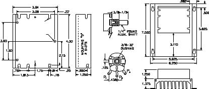
FIGURE 2. MECHANICAL SPECIFICATIONS
|
OPTIONAL AUXILIARY HEATSINK |
|
POTENTIOMETER |
MOUNTING "A" |
CONTROL |
|
|
6 SLOTS |
|
MOUNTING "B" |
|
TAPPED 6-32 |
|
(3 PLACES) |
|
FUSE MOUNTING |
ANTI-ROTATION |
PIN |
|
TAPPED 6-32 |
|
(2 PLACES) |
|
Note: All dimensions are shown in inches.
7

TABLE 1. FIELD CONNECTIONS (SHUNT-WOUND MOTORS ONLY) |
|
|||
CAUTION |
AC LINE |
FIELD VOLTAGE |
FIELD |
FIELD TYPE |
Shunt-wound motors may be |
VOLTAGE |
(VDC) |
CONNECTION |
|
damaged if field remains energized |
115 |
100 |
F+, F- |
Full Voltage |
with the motor stopped for an |
115 |
50 |
F+, L1 |
Half Voltage |
extended period of time, unless |
230 |
200 |
F+, F- |
Full Voltage |
provided with external cooling. |
230 |
100 |
F+, L1 |
Half Voltage |
TABLE 2. ELECTRICAL RATINGS
Model |
Part |
AC |
Motor |
|
No. |
No. |
Line |
Voltage |
|
|
|
Voltage |
(VDC) |
|
|
|
(VAC) |
(3) |
|
|
|
+/- 15% |
|
|
|
|
50/60 |
|
|
|
|
Hz |
|
|
KBIC- |
9429 |
115 |
0 – 90 |
|
120 |
||||
|
|
|
||
KBIC- |
9433 |
115 |
0 – 90 |
|
125 |
||||
|
|
|
||
KBIC- |
9428 |
208/230 |
0 – 180 |
|
240 |
||||
|
|
|
||
KBIC- |
9432 |
208/230 |
0 – 180 |
|
225 |
||||
|
|
|
||
KBIC- |
9464 |
115 |
0 – 90 |
|
240D |
||||
208/230 |
0 – 180 |
|||
(1) |
|
|||
|
|
|
||
KBIC- |
9423 |
115, |
0 – 90 |
|
240DS |
(2)208/230
RATING WITHOUT |
|
RATING WITH |
|
Field |
|||
AUXILLARY HEAT SINK |
AUXILLARY HEAT SINK |
||||||
Max. |
Max. |
|
Max. |
Max. |
|
Voltage |
|
|
|
(Shunt |
|||||
AC |
DC |
|
AC |
DC |
|
||
|
|
Wound |
|||||
Load |
Load |
Max. |
Load |
Load |
Max. |
||
Motor |
|||||||
Current |
Current |
Current |
Current |
||||
HP |
HP |
Only) |
|||||
(RMS |
(Avg. |
(RMS |
(Avg. |
||||
|
|
(VDC) |
|||||
Amps) |
Amps) |
|
Amps) |
Amps) |
|
||
|
|
|
|||||
9.0 |
6.0 |
0.5 |
18.0 |
12.0 |
1 |
50, 100 |
|
12.0 |
8.0 |
0.75 |
24.0 |
16.0 |
1.5 |
50, 100 |
|
9.0 |
6.0 |
1 |
18.0 |
12.0 |
2 |
100, 200 |
|
12.0 |
8.0 |
1.5 |
24.0 |
16.0 |
3 |
100, 200 |
|
9.0 |
6.0 |
0.5 |
18.0 |
12.0 |
1 |
50, 100 |
|
1 |
2 |
100, 200 |
|||||
|
|
|
|
||||
9.0 |
6.0 |
0.5 |
18.0 |
12.0 |
1 |
100 |
|
Notes: (1) Model KBIC-240D is designed to accept 115 or 230 VAC line input to provide 0 - 130 VDC with a 115 or 230 VAC line and 0 - 220 VDC with a 208/230 VAC line. (2) Model KBIC-240DS is designed to accept 115 or 208/230 VAC line input to provide 0-130 VDC with a 115 or 208/230 VAC line. (3) A higher output voltage can be reached by increasing MAX trimpot setting.
8

|
TABLE 3. MINIMUM SUPPLY WIRE SIZE REQUIREMENTS |
|||
Maximum Motor |
Maximum |
Maximum |
Minimum Size Wire (AWG) |
|
Current |
Motor |
Motor |
Cu Only |
|
(DC Amps) |
HP 90 V |
HP 180 V |
Max 50 Foot Run |
Max 100 Foot Run |
6 |
0.5 |
1 |
16 |
14 |
12 |
1 |
2 |
14 |
12* |
16 |
1.5 |
3 |
12 |
12 |
*Minimum recommended wire size. |
|
|
|
|
TABLE 4. FUSE SELECTION CHART* |
||
HORSEPOWER |
Approx. |
Fuse Rating |
|
90 VDC |
180 VDC |
Motor Current |
(AC Amps) |
Motor |
Motor |
(DC Amps) |
|
1/100 |
1/50 |
0.1 |
2/10 |
1/50 |
1/25 |
0.2 |
3/10 |
1/30 |
1/15 |
0.3 |
1/2 |
1/20 |
1/10 |
0.5 |
3/4 |
1/15 |
1/8 |
0.7 |
1 |
1/10 |
1/5 |
1.0 |
1 –1/2 |
1/8 |
1/4 |
1.3 |
2 |
1/6 |
1/3 |
1.7 |
3 |
1/4 |
1/2 |
2.5 |
4 |
1/3 |
3/4 |
3.3 |
5 |
1/2 |
1 |
5.0 |
8 |
3/4 |
1 –1/2 |
7.5 |
12 |
1 |
2 |
10.0 |
15 |
1 –1/2 |
3 |
15.0 |
25 |
*Note: Specific applications may require a different fuse value than indicated. This is based on several factors such as ambient temperatures, duty cycle, motor form factor and CL setpoint.
9
 Loading...