

Page 1
Register
your product
www.kaercher.com/welcome
HDS 9/16-4 ST Gas
HDS 12/14-4 ST Gas
HDS 12/14-4 ST Gas LPG
Deutsch 3
English 23
Français 43
Italiano 63
Nederlands 83
Español 103
Português 123
Dansk 143
Norsk 163
Svenska 183
Suomi 203
Ελληνικά 223
Türkçe 243
Русский 263
Magyar 284
Čeština 304
Slovenščina 324
Polski 344
Româneşte 364
Slovenčina 384
Hrvatski 404
Srpski 424
Български 444
Eesti 465
Latviešu 485
Lietuviškai 505
Українська 525
59671190 04/19
Page 2

2
Page 3
Lesen Sie vor der ersten Benutzung Ihres Gerätes
diese Originalbetriebsanleitung, handeln Sie danach
und bewahren Sie diese für späteren Gebrauch oder für Nachbesitzer auf.
– Vor erster Inbetriebnahme Sicherheitshinweise Nr. 5.956-
309.0 unbedingt lesen!
– Bei Transportschaden sofort Händler informieren.
Inhaltsverzeichnis
Umweltschutz. . . . . . . . . . . . . . DE 1
Gefahrenstufen . . . . . . . . . . . . DE 1
Symbole auf dem Gerät. . . . . . DE 1
Allgemeine Sicherheitshinweise DE 1
Bestimmungsgemäße Verwendung DE 2
Funktion . . . . . . . . . . . . . . . . . . DE 2
Sicherheitseinrichtungen . . . . . DE 2
Geräteelemente . . . . . . . . . . . . DE 3
Inbetriebnahme . . . . . . . . . . . . DE 4
Bedienung . . . . . . . . . . . . . . . . DE 4
Außerbetriebnahme . . . . . . . . . DE 6
Stilllegung . . . . . . . . . . . . . . . . DE 6
Lagerung . . . . . . . . . . . . . . . . . DE 6
Transport . . . . . . . . . . . . . . . . . DE 6
Technische Daten . . . . . . . . . . DE 7
Pflege und Wartung . . . . . . . . . DE 9
Hilfe bei Störungen . . . . . . . . . DE 11
Zubehör . . . . . . . . . . . . . . . . . . DE 13
Anlageninstallation. . . . . . . . . . DE 14
EU-Konformitätserklärung . . . . DE 19
Garantie . . . . . . . . . . . . . . . . . . DE 19
Kundendienst. . . . . . . . . . . . . . DE 20
Umweltschutz
Die Verpackungsmaterialien sind recyclebar. Bitte
werfen Sie die Verpackungen nicht in den Hausmüll,
sondern führen Sie diese einer Wiederverwertung zu.
Altgeräte enthalten wertvolle recyclingfähige Materialien, die einer Verwertung zugeführt werden sollten.
Batterien, Öl und ähnliche Stoffe dürfen nicht in die
Umwelt gelangen. Bitte entsorgen Sie Altgeräte deshalb über geeignete Sammelsysteme.
Bitte Motorenöl, Heizöl, Diesel und Benzin nicht in die Umwelt
gelangen lassen. Bitte Boden schützen und Altöl umweltgerecht
entsorgen.
Kärcher-Reinigungsmittel sind abscheidefreundlich (ASF). Das
bedeutet, dass die Funktion eines Ölabscheiders nicht behindert
wird. Eine Liste mit empfohlenen Reinigungsmitteln ist im Kapitel
„Zubehör“ aufgeführt.
Hinweise zu Inhaltsstoffen (REACH)
Aktuelle Informationen zu Inhaltsstoffen finden Sie unter:
www.kaercher.de/REACH
Gefahrenstufen
GEFAHR
Hinweis auf eine unmittelbar drohende Gefahr, die zu schweren
Körperverletzungen oder zum Tod führt.
몇 WARNUNG
Hinweis auf eine möglicherweise gefährliche Situation, die zu
schweren Körperverletzungen oder zum Tod führen kann.
몇 VORSICHT
Hinweis auf eine möglicherweise gefährliche Situation, die zu
leichten Verletzungen führen kann.
ACHTUNG
Hinweis auf eine möglicherweise gefährliche Situation, die zu
Sachschäden führen kann.
Symbole auf dem Gerät
Hochdruckstrahlen können bei unsachgemäßem Ge-
brauch gefährlich sein. Der Strahl darf nicht auf Personen, Tiere, aktive elektrische Ausrüstung oder auf das Gerät
selbst gerichtet werden.
Allgemeine Sicherheitshinweise
– Jeweilige nationale Vorschriften des Gesetzgebers für Flüs-
sigkeitsstrahler beachten.
– Jeweilige nationale Vorschriften des Gesetzgebers zur Un-
fallverhütung beachten. Flüssigkeitsstrahler müssen regelmäßig geprüft und das Ergebnis der Prüfung schriftlich festgehalten werden.
– Die Heizeinrichtung des Gerätes ist eine Feuerungsanlage.
Feuerungsanlagen müssen regelmäßig nach den jeweiligen
nationalen Vorschriften des Gesetzgebers überprüft werden.
– Bei Betrieb der Anlage in Räumen ist für eine gefahrlose Ab-
leitung der Abgase zu sorgen (Rauchgasrohr ohne Zugunterbrecher). Weiter muss eine ausreichende Frischluftzufuhr
vorhanden sein.
– Sicherheitshinweise, die den verwendeten Reinigungsmitteln
beigestellt sind (i. d. R. auf dem Verpackungsetikett) beachten.
– Am Gerät/Zubehör dürfen keine Veränderungen vorgenom-
men werden.
Vorschriften, Richtlinien und Regeln
Vor der Installation des Gerätes sollte eine Abstimmung mit dem
Gasversorgungsunternehmen und dem Bezirksschornsteinfegermeister erfolgen.
Bei der Installation sind die Vorschriften des Baurechts, des Gewerberechts und des Immissionsschutzes zu beachten. Wir weisen auf die nachstehend aufgeführten Vorschriften, Richtlinien
und Normen hin:
– Das Gerät darf nur von einem Fachbetrieb nach den jeweili-
gen nationalen Vorschriften installiert werden.
– Bei der elektrischen Installation sind die jeweiligen nationalen
Vorschriften des Gesetzgebers zu beachten.
– Bei der Gasinstallation sind die jeweiligen nationalen Vor-
schriften des Gesetzgebers zu beachten.
– Die Installation der Gasleitungen, sowie der gasseitige An-
schluss des Gerätes, darf nur von einer im Gas- und Wasserhandwerk zugelassenen Fachfirma erfolgen.
– Einstellungen, Wartungsarbeiten und Reparaturen am Bren-
ner dürfen nur von geschulten Kärcher-Kundendienstmonteuren durchgeführt werden.
– Bei der Planung eines Kamins müssen die örtlich gültigen
Richtlinien beachtet werden.
- 1
3DE
Page 4
Arbeitsplätze
Der Arbeitsplatz befindet sich am Bedienfeld. Weitere Arbeitsplätze sind je nach Anlagenaufbau an den Zubehörgeräten
(Spritzeinrichtungen), die an den Zapfstellen angeschlossen werden.
Persönliche Schutzausrüstung
Beim Reinigen geräuschverstärkender Teile Gehörschutz zur Vorbeugung von Gehörschäden
tragen.
– Zum Schutz vor zurückspritzendem Wasser oder Schmutz
geeignete Schutzkleidung und Schutzbrille tragen.
Bestimmungsgemäße Verwendung
Das Gerät dient dazu, mittels eines frei austretenden Wasserstrahls Schmutz von Oberflächen zu entfernen. Es wird insbesondere zur Reinigung von Maschinen, Fahrzeugen und Fassaden verwendet.
GEFAHR
Verletzungsgefahr! Beim Einsatz an Tankstellen oder anderen
Gefahrenbereichen entsprechende Sicherheitsvorschriften beachten.
Bitte mineralölhaltiges Abwasser nicht ins Erdreich, Gewässer
oder Kanalisation gelangen lassen. Motorenwäsche und Unterbodenwäsche deshalb bitte nur an geeigneten Plätzen mit Ölabscheider durchführen.
Anforderungen an die Wasserqualität:
ACHTUNG
Als Hochdruckmedium darf nur sauberes Wasser verwendet
werden. Verschmutzungen führen zu vorzeitigem Verschleiß
oder Ablagerungen im Gerät und im Zubehör.
Wird Recyclingwasser verwendet, dürfen folgende Grenzwerte
nicht überschritten werden.
pH-Wert 6,5...9,5
elektrische Leitfähigkeit * Leitfähigkeit Frischwasser
+1200 µS/cm
absetzbare Stoffe ** < 0,5 mg/l
abfiltrierbare Stoffe *** < 50 mg/l
Kohlenwasserstoffe < 20 mg/l
Chlorid < 300 mg/l
Sulfat < 240 mg/l
Kalzium < 200 mg/l
Gesamthärte < 28 °dH
< 50 °TH
< 500 ppm (mg CaCO
Eisen < 0,5 mg/l
Mangan < 0,05 mg/l
Kupfer < 2 mg/l
Aktivchlor < 0,3 mg/l
frei von üblen Gerüchen
* Maximum insgesamt 2000 µS/cm
** Probevolumen 1 l, Absetzzeit 30 min
*** keine abrasiven Stoffe
/l)
3
Funktion
– Das Kaltwasser gelangt über die Motorkühlschlange in den
Schwimmerbehälter und von dort in den Außenmantel des
Durchlauferhitzers und weiter zur Saugseite der Hochdruckpumpe. Im Schwimmerbehälter wird Enthärter zudosiert. Die
Pumpe fördert Wasser und angesaugtes Reinigungsmittel
durch den Durchlauferhitzer. Der Anteil von Reinigungsmittel
im Wasser kann durch ein Dosierventil eingestellt werden.
Der Durchlauferhitzer wird mit einem Gasbrenner beheizt.
– Der Hochdruckausgang wird an ein im Gebäude vorhande-
nes Hochdrucknetz angeschlossen. An den Zapfstellen dieses Netzes erfolgt der Anschluss der Handspritzpistole mit einem Hochdruckschlauch.
Sicherheitseinrichtungen
Sicherheitseinrichtungen dienen dem Schutz des Benutzers und
dürfen nicht außer Kraft gesetzt oder in ihrer Funktion umgangen
werden.
Wassermangelsicherung Schwimmerbehälter
Die Wassermangelsicherung verhindert das Einschalten der
Hochdruckpumpe bei Wassermangel.
Wassermangelsicherung Sicherheitsblock
Die Wassermangelsicherung verhindert die Überhitzung des
Brenners bei Wassermangel. Nur bei ausreichender Wasserversorgung geht der Brenner in Betrieb.
Druckschalter
Der Druckschalter schaltet das Gerät bei Überschreiten des Arbeitsdruckes aus. Die Einstellung darf nicht verändert werden.
Sicherheitsventil
Bei einer Störung des Druckschalters öffnet das Sicherheitsventil. Dieses Ventil ist werkseitig eingestellt und verplombt. Die Einstellung darf nicht verändert werden.
Flammenüberwachung
Bei Brennstoffmangel oder Brennerstörung schaltet die Flammenüberwachung den Brenner ab. Die Kontrolllampe Brennerstörung (E) leuchtet auf.
Überstromschutz
Ist der Brennermotor blockiert, löst der Überstromschutzschalter
aus. Der Motor der Hochdruckpumpe ist mit einem Motorschutzschalter und einem Wicklungsschutzschalter abgesichert.
Abgasthermostat
Der Abgasthermostat löst aus, wenn die Abgastemperatur
320 °C übersteigt. Die Kontrolllampe Abgasthermostat (K) leuchtet.
Temperaturbegrenzer
Die Maximaltemperaturbegrenzer im Kesselboden (> 80 °C) und
im Wasserausgang (> 110 °C) lösen aus und die Kontrolllampe
Brennerstörung (E) leuchtet.
Abgasdruckschalter
Der Abgasdruckschalter schaltet den Brenner ab, wenn im Abgassystem ein unzulässig hoher Gegendruck entsteht, z. B. bei
Verstopfung.
Druckentlastung Hochdrucksystem
Nach Abschalten des Gerätes über die Handspritzpistole öffnet
nach Ablauf der Betriebsbereitschaftszeit ein im Hochdrucksystem angeordnetes Magnetventil, wodurch der Druck absinkt.
Sicherungsraste
Die Sicherungsraste an der Handspritzpistole verhindert unbeabsichtigtes Einschalten des Gerätes.
4 DE
- 2
Page 5
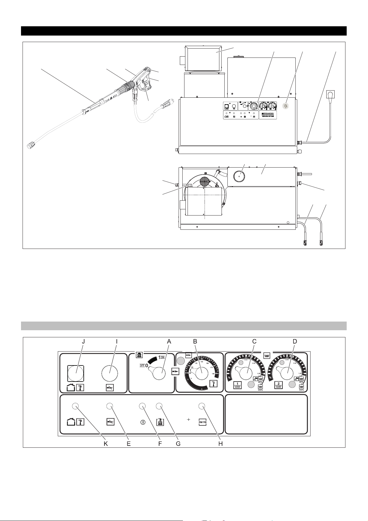
Geräteelemente
12
13
14
151617
4
8
1 11 2 9
10
6 7
3
5
Bild 1
1 Brenner
2 Manometer
3 Frischwasser-Zulauf mit Sieb
4 Hochdruckausgang EASY!Lock
5 Gasanschluss
6 Reinigungsmittel-Saugschlauch I
7 Reinigungsmittel-Saugschlauch II (Option)
8 Enthärterbehälter
9 Elektrozuleitung
10 Schwimmerbehälter
11 Bedienfeld
12 Sicherungshebel
13 Abzugshebel
14 Sicherungsraste der Handspritzpistole
15 Handspritzpistole EASY!Force
16 Druck-/Mengenregulierung an der Handspritzpistole
17 Strahlrohr EASY!Lock
Bedienfeld
Bild 2
A Geräteschalter
B Temperaturregler
C Reinigungsmittel-Dosierventil I
D Reinigungsmittel-Dosierventil II (Option)
E Kontrolllampe Brennerstörung
F Kontrolllampe Betriebsbereitschaft
G Kontrolllampe Motorüberhitzung
H Kontrolllampe Verkalkungsschutz
I Entriegelungstaste Gasrelais
J Entriegelungstaste Abgasthermostat
K Kontrolllampe Abgasthermostat
- 3
5DE
Page 6
Inbetriebnahme
!
몇 WARNUNG
Verletzungsgefahr! Gerät, Zubehör, Zuleitungen und Anschlüsse
müssen in einwandfreiem Zustand sein. Falls der Zustand nicht
einwandfrei ist, darf das Gerät nicht benutzt werden.
Stromanschluss
– Anschlusswerte siehe Technische Daten und Typenschild.
– Der elektrische Anschluss muss von einem Elektroinstalla-
teur ausgeführt werden und IEC 60364-1 entsprechen.
Bedienung
GEFAHR
Explosionsgefahr! Keine brennbaren Flüssigkeiten versprühen.
GEFAHR
Verletzungsgefahr! Gerät nie ohne montiertes Strahlrohr verwenden. Strahlrohr vor jeder Benutzung auf festen Sitz überprüfen.
Verschraubung des Strahlrohrs muss handfest angezogen sein.
GEFAHR
Verletzungsgefahr! Beim Arbeiten Handspritzpistole und Strahlrohr mit beiden Händen halten.
GEFAHR
Verletzungsgefahr! Der Abzugshebel und der Sicherungshebel
dürfen bei Betrieb nicht festgeklemmt werden.
GEFAHR
Verletzungsgefahr! Bei defektem Sicherungshebel Kundendienst
aufsuchen.
Sicherheitshinweise
Der Benutzer hat das Gerät bestimmungsgemäß zu verwenden.
Er hat die örtlichen Gegebenheiten zu berücksichtigen und beim
Arbeiten mit dem Gerät auf Personen im Umfeld zu achten.
Das Gerät niemals unbeaufsichtigt lassen, solange das Gerät in
Betrieb ist.
GEFAHR
– Verbrühungsgefahr durch Heißwasser! Wasserstrahl nicht
auf Personen oder Tiere richten.
– Verbrennungsgefahr durch heiße Anlagenteile! Bei Heißwas-
serbetrieb unisolierte Rohrleitungen und Schläuche nicht berühren. Strahlrohr nur an den Griffschalen festhalten. Abgasstutzen des Durchlauferhitzers nicht berühren.
– Vergiftungs- oder Verätzungsgefahr durch Reinigungsmittel!
Hinweise auf den Reinigungsmitteln beachten. Reinigungsmittel für Unbefugte unzugänglich aufbewahren.
GEFAHR
Lebensgefahr durch elektrischen Schlag! Richten Sie den Wasserstrahl nicht auf folgende Einrichtungen:
– Elektrische Geräte und Anlagen,
– diese Anlage selbst,
– alle stromführenden Teile im Arbeitsbereich.
Durch den aus dem Strahlrohr austretenden Wasserstrahl entsteht eine Rückstoßkraft. Durch das abgewinkelte Strahlrohr
wirkt eine Kraft nach oben.
GEFAHR
– Verletzungsgefahr! Der Rückstoß des Strahlrohres kann Sie
aus dem Gleichgewicht bringen. Sie können stürzen. Das
Strahlrohr kann umherfliegen und Personen verletzen. Sicheren Standplatz suchen und Pistole gut festhalten.
– Den Strahl nicht auf andere oder sich selbst richten, um Klei-
dung oder Schuhwerk zu reinigen.
– Verletzungsgefahr durch wegfliegende Teile! Wegfliegende
Bruchstücke oder Gegenstände können Personen oder Tiere
verletzen. Den Wasserstrahl nie auf zerbrechliche oder lose
Gegenstände richten.
– Unfallgefahr infolge Beschädigung! Reifen und Ventile mit ei-
nem Mindestabstand von 30 cm reinigen.
몇 WARNUNG
Gefahr durch gesundheitsgefährdende Stoffe! Folgende Materialien nicht abspritzen, da gesundheitsgefährdende Stoffe aufgewirbelt werden können:
– Asbesthaltige Materialien,
– Materialien, die möglicherweise gesundheitsgefährdende
Stoffe enthalten.
GEFAHR
– Verletzungsgefahr durch austretenden, eventuell heißen
Wasserstrahl! Nur Original Kärcher-Hochdruckschläuche
sind optimal auf die Anlage abgestimmt. Bei Verwendung anderer Schläuche wird keine Gewähr übernommen.
– Gesundheitsgefahr durch Reinigungsmittel! Durch gegebe-
nenfalls beigemischte Reinigungsmittel besitzt das vom Gerät abgegebene Wasser keine Trinkwasserqualität.
– Gefahr von Gehörschäden durch Arbeiten an geräuschver-
stärkenden Teilen! In diesem Fall Gehörschutz tragen.
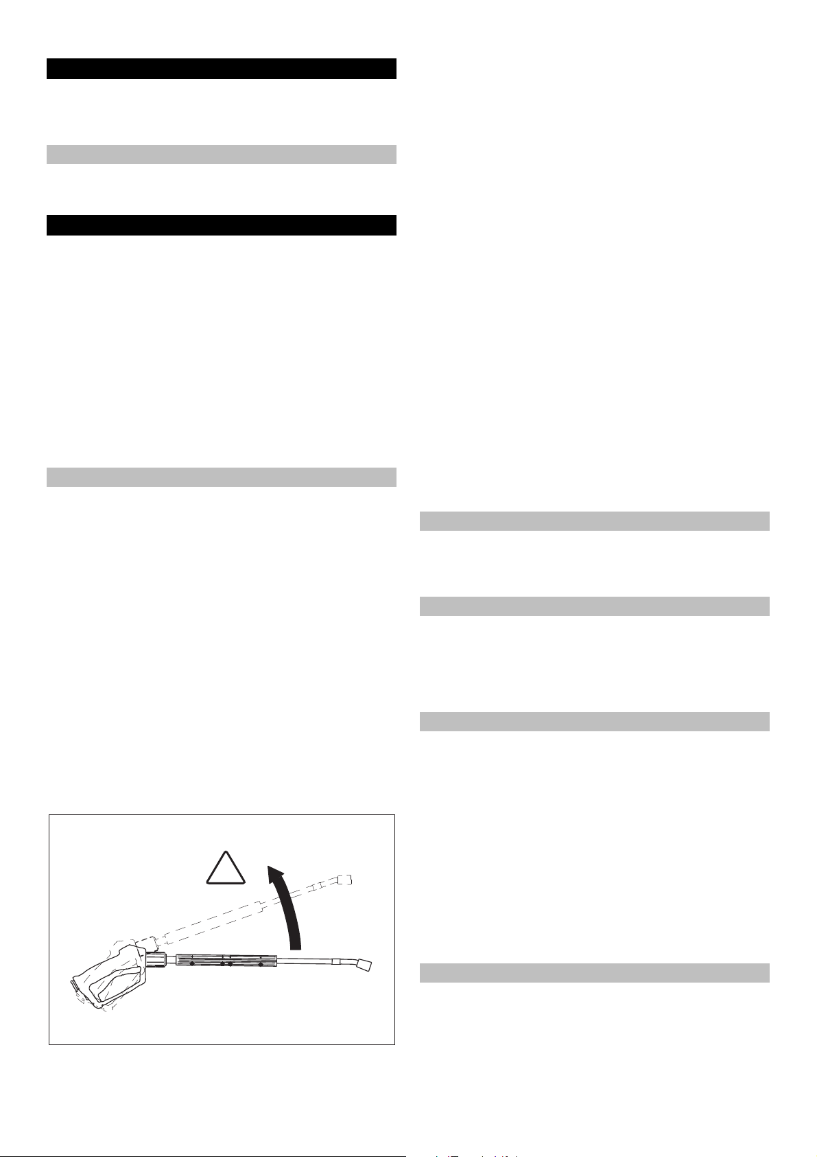
Handspritzpistole öffnen/schließen
Handspritzpistole öffnen: Sicherungshebel und Abzugshebel
betätigen.
Handspritzpistole schließen: Sicherungshebel und Abzugs-
hebel loslassen.
Düse wechseln
GEFAHR
Verletzungsgefahr! Gerät vor Düsenwechsel ausschalten und
Handspritzpistole betätigen, bis Gerät drucklos ist.
Handspritzpistole sichern, dazu Sicherungsraste nach vorne
schieben.
Düse wechseln.
Betriebsbereitschaft herstellen
GEFAHR
Verletzungsgefahr durch austretenden, eventuell heißen Wasserstrahl!
GEFAHR
Hochdruckschlauch vor jedem Betrieb auf Schäden prüfen. Beschädigten Hochdruckschlauch unverzüglich austauschen.
Hochdruckschlauch, Rohrleitungen, Armaturen und Strahl-
rohr vor jeder Benutzung auf Beschädigung prüfen.
Schlauchkupplung auf festen Sitz und Dichtheit überprüfen.
ACHTUNG
Beschädigungsgefahr durch Trockenlauf.
Füllstand der Reinigungsmittelbehälter überprüfen und bei
Bedarf nachfüllen.
Enthärterflüssigkeitsstand überprüfen und bei Bedarf nach-
füllen.
Ausschalten im Notfall
Geräteschalter (A) auf „0“ drehen.
Wasserzulauf schließen.
Handspritzpistole betätigen, bis das Gerät drucklos ist.
Gaszufuhr schließen.
6 DE
- 4
Page 7
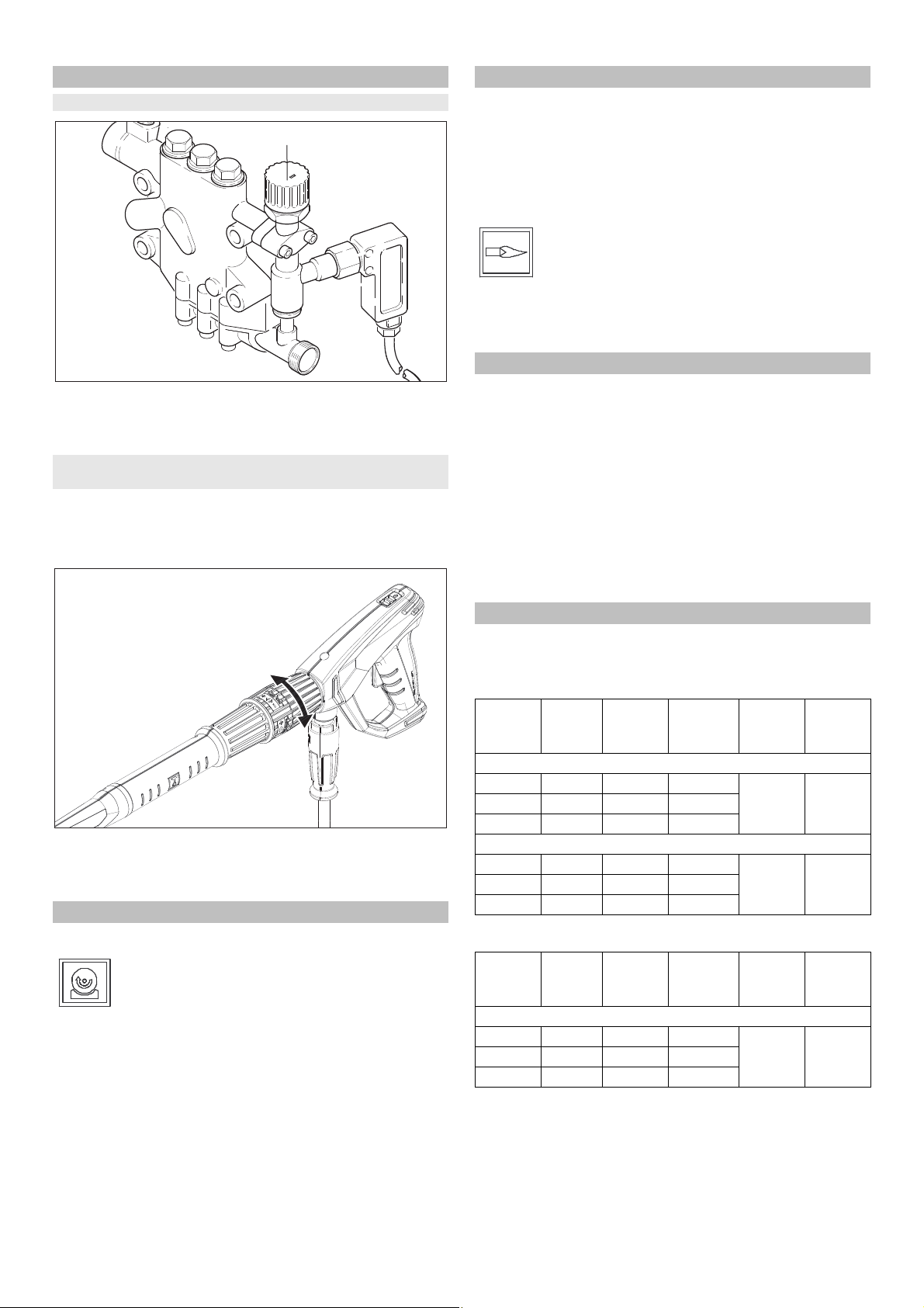
Arbeitsdruck und Fördermenge einstellen
R
Einstellung am Gerät
Mengenregulierventil im Uhrzeigersinn drehen ergibt höhe-
ren Arbeitsdruck und größere Fördermenge.
Mengenregulierventil gegen den Uhrzeigersinn drehen ergibt
geringeren Arbeitsdruck und kleinere Fördermenge.
Einstellung an der Druck-/Mengenregulierung der Handspritzpistole (Option)
GEFAHR
Verletzungsgefahr! Beim Einstellen der Druck-/Mengenregulierung darauf achten, dass sich die Verschraubung des Strahlrohrs
nicht löst.
Rechtsdrehung des Wassermengenreglers ergibt größere
Fördermenge und höheren Arbeitsdruck.
Linksdrehung des Wassermengenreglers ergibt geringere
Fördermenge und geringeren Arbeitsdruck.
Betrieb mit Kaltwasser
Wasserzulauf öffnen.
Symbol „Motor ein“
Handspritzpistole entsichern, dazu Sicherungsraste nach
hinten schieben.
Handspritzpistole öffnen und Geräteschalter (A) auf „1“ (Mo-
tor ein) stellen.
Die Kontrolllampe Betriebsbereitschaft (F) zeigt Betriebsbe-
reitschaft an.
Betrieb mit Heißwasser
GEFAHR
Verbrühungsgefahr!
ACHTUNG
Heißwasserbetrieb ohne Brennstoff führt zur Beschädigung der
Brennstoffpumpe. Vor dem Heißwasserbetrieb Brennstoffversorgung sicherstellen.
Der Brenner kann bei Bedarf zugeschaltet werden.
Symbol „Brenner ein“
Geräteschalter (A) auf „Brenner ein“ stellen.
Gewünschte Wassertemperatur am Temperaturregler (B)
einstellen. Höchsttemperatur ist 98 °C.
Betriebsbereitschaft
– Wird die Handspritzpistole während des Betriebes geschlos-
sen, schaltet das Gerät ab.
– Beim erneuten Öffnen der Pistole innerhalb der einstellbaren
Betriebsbereitschaftszeit (2…8 Minuten) läuft das Gerät
selbsttätig wieder an.
– Wird die Betriebsbereitschaftszeit überschritten, schaltet die
Sicherheitszeitschaltung Pumpe und Brenner ab. Die Kontrolllampe Betriebsbereitschaft (F) erlischt.
– Zur Wiederinbetriebnahme den Geräteschalter auf Stellung
„0“ stellen, dann wieder einschalten. Wird das Gerät mit einer
Fernbedienung gesteuert, kann die Wiederinbetriebnahme
am entsprechenden Schalter der Fernbedienung ausgeführt
werden.
Düsenauswahl
– Fahrzeugreifen werden nur mit der Flachstrahldüse (25°) und
einem Mindest-Spritzabstand von 30 cm gereinigt. Mit dem
Rundstrahl dürfen Reifen auf keinen Fall gereinigt werden.
Für alle anderen Aufgaben stehen folgende Düsen zur Auswahl:
Verschmutzung
stark 00060 0° 5.765-240 16 46
mittel 25060 25° 5.765-027
leicht 40060 40° 5.130-087
stark 00080 0° 5.765-243 14 55
mittel 25080 25° 5.765-061
leicht 40080 40° 5.765-221
Bei mehr als 20 m Rohrleitung oder mehr als 2 x 10 m Hochdruckschlauch NW 8 sind folgende Düsen zu verwenden:
Verschmutzung
stark 0075 0° 5.765-242 10 37
mittel 2575 25° 5.765-057
leicht 4075 40° 5.765-220
Düse Spritzwin-
kel
HDS 9/16
HDS 12/14
Düse Spritzwin-
kel
HDS 9/16
Teile-Nr. Druck
[MPa]
Teile-Nr. Druck
[MPa]
Rückstoß
[N]
Rückstoß
[N]
- 5
7DE
Page 8
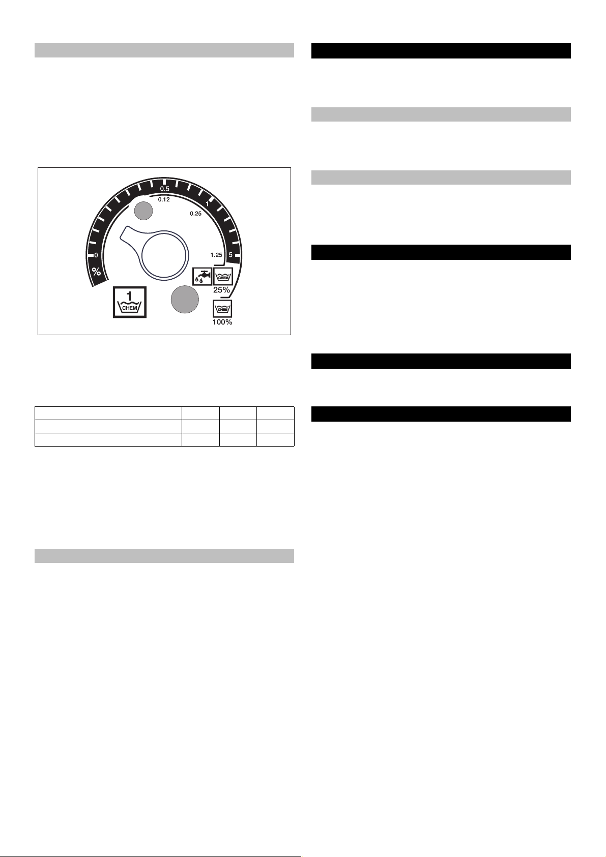
Reinigungsmittel-Dosierung
– Reinigungsmittel erleichtern die Reinigungsaufgabe. Sie wer-
den aus einem externen Reinigungsmitteltank angesaugt.
– Das Gerät ist in der Grundausstattung mit einem Dosierventil
(C) ausgestattet. Eine zweite Dosiereinrichtung (Dosierventil
D) ist als Sonderzubehör erhältlich. Dann besteht die Möglichkeit, zwei verschiedene Reinigungsmittel anzusaugen.
– Die Dosiermenge wird an den Reinigungsmittel-Dosierventi-
len (C oder D) am Bedienfeld eingestellt. Der eingestellte
Wert entspricht dem Reinigungsmittelanteil in Prozent.
– Die äußere Skala gilt bei Verwendung von unverdünntem
Reinigungsmittel (100 % CHEM).
– Die innere Skala gilt bei Verwendung von 1+3 vorverdünntem
Reinigungsmittel (25 % CHEM + 75 % Wasser).
Folgende Tabelle gibt den Reinigungsmittelverbrauch für die
Werte auf der äußeren Skala an:
Stellung 0,5 1 8
Reinigungsmittelmenge [l/h] 14...15 22...24 50
Reinigungsmittelkonzentration [%] 1,5 2,5 > 5
Die genaue Dosiermenge ist abhängig von:
– Viskosität des Reinigungsmittels
– Ansaughöhe
– Strömungswiderstand der Hochdruckleitung
Ist eine exakte Dosierung erforderlich, so ist die angesaugte Reinigungsmittelmenge auszumessen (z. B. durch Saugen aus einem Messbecher).
Hinweis: Reinigungsmittel-Empfehlungen finden Sie im Kapitel
„Zubehör“.
Enthärter nachfüllen
ACHTUNG
Bei Betrieb ohne Enthärter kann der Durchlauferhitzer verkalken.
Bei leerem Enthärterbehälter blinkt die Kontrolllampe Verkalkungsschutz (H).
Bild 1 - Pos. 8
Enthärterbehälter mit Enthärterflüssigkeit RM 110 (2.780-
001) nachfüllen.
Außerbetriebnahme
GEFAHR
Verbrühungsgefahr durch heißes Wasser! Nach dem Betrieb mit
Heißwasser muss das Gerät zur Abkühlung mindestens zwei Minuten mit Kaltwasser bei geöffneter Pistole betrieben werden.
Nach Betrieb mit Reinigungsmittel
Bei Heißwasserbetrieb den Temperaturregler (B) auf die
niedrigste Temperatur einstellen.
Gerät mindestens 30 Sekunden ohne Reinigungsmittel be-
nutzen.
Gerät ausschalten
Geräteschalter (A) auf „0“ drehen.
Wasserzulauf schließen.
Handspritzpistole betätigen, bis das Gerät drucklos ist.
Handspritzpistole mit Sicherungsraste gegen unbeabsichtig-
tes Öffnen sichern.
Stilllegung
Bei längeren Betriebspausen oder wenn eine frostfreie Lagerung
nicht möglich ist, folgende Maßnahmen durchführen (siehe Kapitel „Pflege und Wartung“, Abschnitt „Frostschutz“):
Wasser ablassen.
Gerät mit Frostschutzmittel durchspülen.
Hauptschalter abschalten und sichern bzw. Cekon-Stecker
ausstecken.
Gaszufuhr schließen.
Lagerung
몇 VORSICHT
Verletzungs- und Beschädigungsgefahr! Gewicht des Gerätes
bei Lagerung beachten.
Transport
ACHTUNG
Abzugshebel während des Transports vor Beschädigung schützen.
몇 VORSICHT
Verletzungs- und Beschädigungsgefahr! Gewicht des Gerätes
beim Transport beachten.
Beim Transport in Fahrzeugen Gerät nach den jeweils gülti-
gen Richtlinien gegen Rutschen und Kippen sichern.
8 DE
- 6
Page 9

Technische Daten
HDS 9/16-4 ST
Gas
HDS 12/14-4 ST
Gas
HDS 12/14-4 ST
Gas LPG
1.251-900 1.251-901 1.251-902
Leistungsdaten
Arbeitsdruck Wasser (mit Standarddüse) MPa (bar) 16 (160) 14 (140) 14 (140)
Max. Betriebsüberdruck (Sicherheitsventil) MPa (bar) 18,5 (185) 18,5 (185) 18,5 (185)
Fördermenge Wasser (stufenlos regelbar) l/h (l/min) 500-1000 (8,3-
600-1200 (10-20) 600-1200 (10-20)
16,6)
Reinigungsmittelansaugung (stufenlos regelbar) l/h (l/min) 0-50 (0-0,8) 0-60 (0-1) 0-60 (0-1)
Wasseranschluss
Zulaufmenge (min.) l/h (l/min) 1100 (18,3) 1300 (21,7) 1300 (21,7)
Zulaufdruck (min.) MPa (bar) 0,1 (1) 0,1 (1) 0,1 (1)
Zulaufdruck (max.) MPa (bar) 0,6 (6) 0,6 (6) 0,6 (6)
Elektrischer Anschluss
Stromart -- 3N~ 3N~ 3N~
Frequenz Hz 50 50 50
Spannung V 380-420 380-420 380-420
Anschlussleistung kW 6,4 7,5 7,5
Elektrische Absicherung (träge) A 16 20 20
Schutzart -- IPX5 IPX5 IPX5
Schutzklasse -- I I I
Maximal zulässige Netzimpedanz Ohm (0,381+j 0,238) -- -Elektrozuleitung mm
2
5 x 2,5 5 x 2,5 5 x 2,5
Temperatur
Zulauftemperatur (max.) °C 30 30 30
Max. Arbeitstemperatur Heißwasser °C 98 98 98
Max. Temperatur Sicherheitsthermostat °C 110 110 110
Temperaturerhöhung bei max. Wasserdurchsatz °C 60-65 60-65 60-65
Heizleistung netto (Hi) kW 70 95 95
Kaminzug kPa 0,01-0,04 0,01-0,04 0,01-0,04
Gas-Anschlusswerte
3
Erdgas E (G 20) m
Erdgas LL (G 25) m
/h 7,2 9,8 --
3
/h 8,2 11,4 -Nennanschlussdruck (Erdgas) kPa 1,8-5 1,8-5 -Propan kg/h -- -- 7,2
Nennanschlussdruck (Propan) kPa -- -- 5-6
Umweltdaten
Normnutzungsgrad % 97 97 97
Normemissionsfaktor NO
(Erdgas G 25) mg/kWh < 40 < 40 --
X
Normemissionsfaktor CO (Erdgas G 25) mg/kWh < 40 < 40 --
Werte zur Schornsteinbemessung
Überdruckeignung (min.) kPa 0,05 0,05 0,05
Zugbedarf kPa 0 0 0
Abgasmassenstrom - Volllast kg/h 130 166 166
(Erdgas) % 9,5 9,5 --
CO
2
(Propan) % -- -- 12
CO
2
Abgastemperatur max./min. °C 190/150 170/130 170/130
Verbrennungsluft/Luftzufuhr Max. Länge: 10 m mit zwei 90° Bögen (Mindestdurchmesser 100 mm).
Nach örtlichen Vorschriften aus dem Aufstellungsraum oder Frischluft
von außen.
Kondensatablass
Kondensatablass (max.) l/h 4 (über Siphon in
Kanalisation)
4 (über Siphon in
Kanalisation)
4 (über Siphon in
Kanalisation)
Anschluss DN 40 (HTR) 40 (HTR) 40 (HTR)
Minimale Wassersäule, Siphon mm 300 300 300
Geräte-Kategorie Europa -- I 2E (r), I 2ELL, I
2H, I 2L, I2 HE
I 2E (r), I 2ELL, I
2H, I 2L, I2 HE
I 3P
- 7
9DE
Page 10
HDS 9/16-4 ST
Gas
Gerätetyp -- B23, C33, C43,
C53
HDS 12/14-4 ST
Gas
B23, C33, C43,
C53
HDS 12/14-4 ST
Gas LPG
B23, C33, C43,
C53
CE-Produkt-Identnummer -- PIN 0063 BN 3880 PIN 0063 BN 3880 PIN 0063 BN 3880
Maße und Gewichte
Länge mm 1124 1124 1124
Breite mm 558 558 558
Höhe mm 966 1076 1076
Typisches Betriebsgewicht kg 193,5 209 209
Ermittelte Werte gemäß EN 60335-2-79
Geräuschemission
Schalldruckpegel L
Unsicherheit K
pA
pA
dB(A)747676
dB(A)111
Hand-Arm Vibrationswert
Handspritzpistole m/s
Strahlrohr m/s
Unsicherheit K m/s
2
2
2
2,2 2,3 2,3
1,8 2,1 2,1
1,0 1,0 1,0
Maßblatt
10 DE
- 8
Page 11
Pflege und Wartung
GEFAHR
Verletzungsgefahr! Vor allen Wartungs- und Reparaturarbeiten ist der Hauptschalter auszuschalten bzw. der Cekon-Stecker auszustecken.
Wartungsplan
Zeitpunkt Tätigkeit betroffene Baugruppe Durchführung von wem
täglich Handspritzpisto-
le prüfen
HochdruckSchläuche prüfen
Anschlussleitung mit Netzstecker prüfen
wöchentlich oder
nach 40 Betriebsstunden
monatlich oder
nach 200 Betriebsstunden
nach 500-700 Betriebsstunden
halbjährlich oder
nach 1000 Betriebsstunden
jährlich Sicherheitsüber-
Ölzustand prüfen Ölbehälter an der Pumpe Ist das Öl milchig, muss es gewechselt werden. Bediener
Ölstand überprü-
fen
Sieb reinigen Sieb im Wassereingang Siehe Abschnitt „Siebe reinigen“. Bediener
Pumpe prüfen Hochdruckpumpe Pumpe auf Undichtigkeit untersuchen. Bei mehr
auf innere Ablagerungen prüfen
Sieb reinigen Sieb in der Wassermangelsi-
Austausch Glühzünder, Ionisationselektro-deGlühzünder bzw. Ionisationselektrode erneuern. Kunden-
Ölwechsel Hochdruckpumpe Öl ablassen. 1 l neues Öl (Best.-Nr. 6.288-016)
prüfen, reinigen gesamte Anlage Sichtkontrolle der Anlage, Hochdruckanschlüsse
Schlauch ersetzen
prüfung
Handspritzpistole Überprüfen, ob Handspritzpistole dicht schließt.
Funktion der Sicherung gegen unbeabsichtigte
Bedienung prüfen. Defekte Handspritzpistolen
austauschen.
Ausgangsleitungen, Schläuche
zum Arbeitsgerät
Elektrischer Anschluss mit Stecker/Steckdose
Ölbehälter an der Pumpe Ölstand der Pumpe überprüfen. Bei Bedarf Öl
gesamte Anlage Anlage mit Strahlrohr ohne Hochdruck-Düse in
cherung
Schlauch zum Abgasdruckschalter
gesamte Anlage Sicherheitsüberprüfung nach den jeweiligen nati-
Schläuche auf Beschädigung untersuchen. Defekte Schläuche sofort auswechseln. Unfallgefahr!
Anschlussleitung mit Netzstecker auf Schäden
prüfen. Beschädigte Anschlussleitung unverzüglich durch autorisierten Kundendienst/ElektroFachkraft austauschen lassen.
(Best.-Nr. 6.288-016) nachfüllen.
als 3 Tropfen pro Minute Kundendienst rufen.
Betrieb nehmen. Steigt der Betriebsdruck am Gerätemanometer über 3 MPa an, so muss die Anlage entkalkt werden. Dasselbe gilt auch, wenn
beim Betrieb ohne Hochdruckleitung (Wasser tritt
am Hochdruckausgang frei aus) ein Betriebsdruck von mehr als 0,7–1 MPa festgestellt wird.
Siehe Abschnitt „Siebe reinigen“. Bediener
einfüllen. Füllstand am Ölbehälter kontrollieren.
auf Dichtheit prüfen, Überströmventil auf Dichtheit prüfen, Hochdruckschlauch prüfen, Druckspeicher prüfen, Heizschlange entkalken, Ionisationselektrode reinigen / erneuern, Brenner einstellen.
Schlauch erneuern. Kunden-
onalen Vorschriften des Gesetzgebers für Flüssigkeitsstrahler durchführen.
Bediener
Bediener
Bediener
Bediener
Bediener
Bediener mit
Einweisung
für Entkalkung
dienst
Bediener
Kundendienst
dienst
Sachkundi-
ger
- 9
11DE
Page 12
Wartungsvertrag
2.
1.
Mit dem zuständigen Kärcher-Verkaufsbüro kann ein Wartungsvertrag für das Gerät abgeschlossen werden.
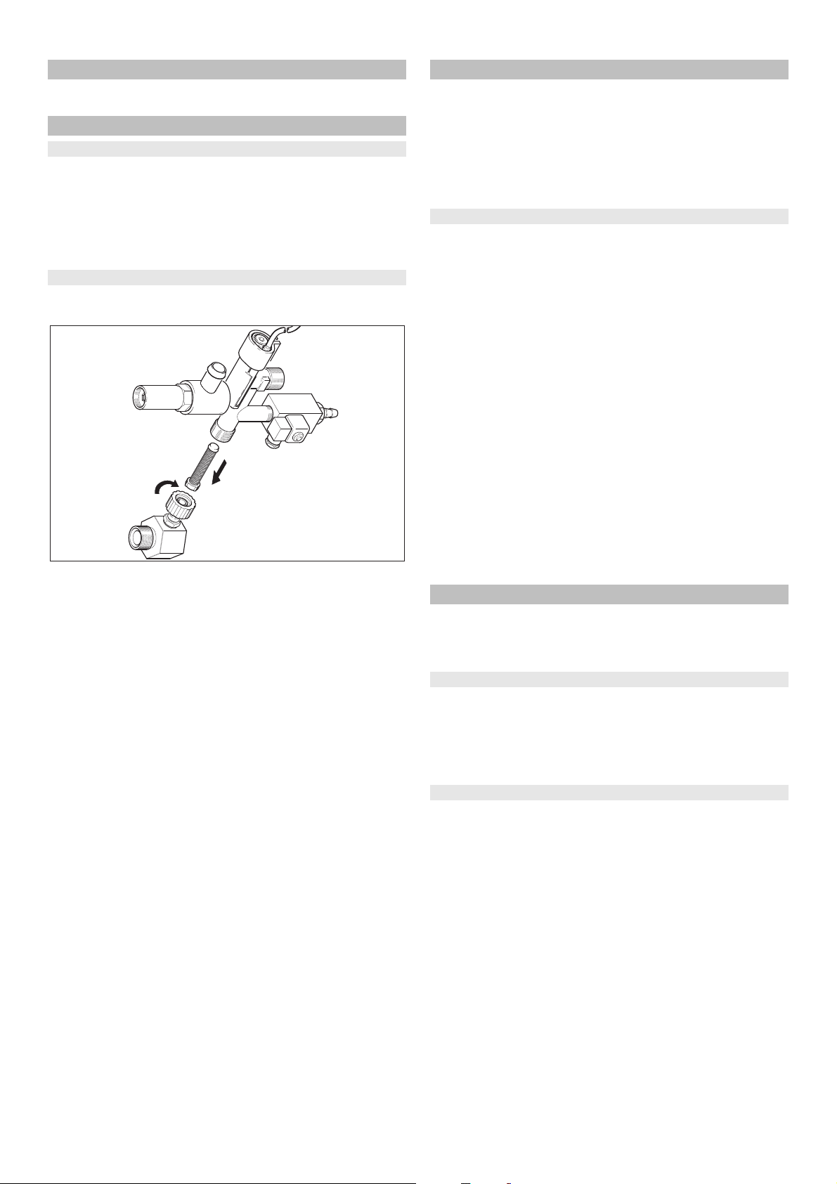
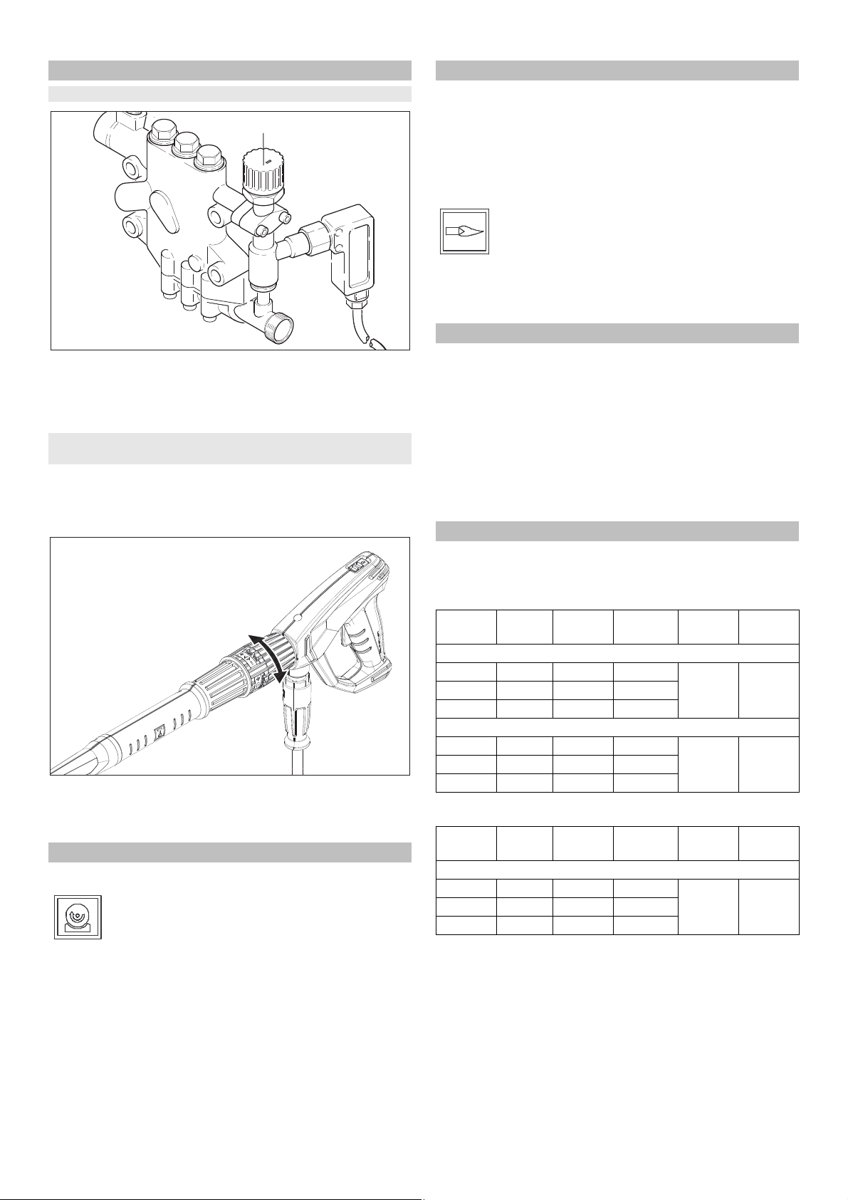
Siebe reinigen
Sieb im Wassereingang
Bild 1 - Pos. 3
Wasserzulauf schließen.
Wasserzulaufschlauch am Gerät abschrauben.
Sieb mit einem Schraubendreher aus dem Anschluss heraus-
schieben.
Sieb reinigen
In umgekehrter Reihenfolge wieder montieren.
Sieb in der Wassermangelsicherung
Verkleidungsbleche abnehmen.
Winkelstück vom Sicherheitsblock abschrauben.
Schraube M8x30 in das Sieb drehen.
Schraube und Sieb mit einer Zange herausziehen.
Sieb reinigen
In umgekehrter Reihenfolge wieder montieren.
Entkalken
Bei Ablagerungen in den Rohrleitungen steigt der Strömungswiderstand, so dass der Druckschalter auslösen kann.
GEFAHR
Explosionsgefahr durch brennbare Gase! Beim Entkalken ist
Rauchen verboten. Für gute Belüftung sorgen.
GEFAHR
Verätzungsgefahr durch Säure! Schutzbrille und Schutzhandschuhe tragen.
Durchführung
Zur Entfernung dürfen nach gesetzlichen Vorschriften nur geprüfte Kesselsteinlösemittel mit Prüfzeichen benutzt werden.
– RM 100 (Best.-Nr. 6.287-008) löst Kalkstein und einfache
Verbindungen aus Kalkstein und Waschmittelrückständen.
– RM 101 (Best.-Nr. 6.287-013) löst Ablagerungen, die mit RM
100 nicht ablösbar sind.
Einen 20-Liter-Behälter mit 15 l Wasser füllen.
Einen Liter Kesselsteinlösemittel dazugeben.
Wasserschlauch direkt am Pumpenkopf anschließen und
freies Ende in den Behälter hängen.
Das angeschlossene Strahlrohr ohne Düse in den Behälter
stecken.
Handspritzpistole öffnen und während des Entkalkens nicht
wieder schließen.
Geräteschalter auf „Brenner ein“ schalten, bis ca. 40 °C er-
reicht sind.
Gerät abschalten und 20 Minuten stehen lassen. Die
Handspritzpistole muss geöffnet bleiben.
Gerät anschließend leerpumpen.
Hinweis: Wir empfehlen zum Korrosionsschutz und zur Neutralisierung der Säurereste anschließend eine alkalische Lösung
(z.B. RM 81) über den Reinigungsmittelbehälter durch das Gerät
zu pumpen.
Frostschutz
Das Gerät soll in frostgeschützten Räumen aufgestellt werden.
Bei Frostgefahr, z. B. bei Installationen im Außenbereich, muss
das Gerät entleert und mit Frostschutzmittel durchgespült werden.
Wasser ablassen
Wasserzulaufschlauch und Hochdruckschlauch abschrau-
ben.
Gerät max. 1 Minute laufen lassen bis Pumpe und Leitungen
leer sind.
Zulaufleitung am Kesselboden abschrauben und Heizschlan-
ge leerlaufen lassen.
Gerät mit Frostschutzmittel durchspülen
Hinweis: Handhabungsvorschriften des Frostschutzmittelher-
stellers beachten.
Handelsübliches Frostschutzmittel in Schwimmerbehälter bis
oben hin einfüllen.
Auffangbehälter unter den Hochdruck-Ausgang stellen.
Gerät einschalten und so lange laufen lassen, bis die Was-
sermangelsicherung Schwimmerbehälter anspricht und das
Gerät abschaltet.
Kesselboden und Siphon mit Frostschutzmittel befüllen.
Dadurch wird auch ein gewisser Korrosionsschutz erreicht.
12 DE
- 10
Page 13
Hilfe bei Störungen
GEFAHR
Verletzungsgefahr! Vor allen Wartungs- und Reparaturarbeiten ist der Hauptschalter auszuschalten bzw. der Cekon-Stecker auszustecken.
Störung Mögliche Ursache Behebung von wem
Gerät läuft nicht, Kontrolllampe Betriebsbereitschaft (F)
leuchtet nicht
+ Kontrolllampe Motorüberhitzung (G) leuchtet
Brenner zündet nicht oder
Flamme erlischt während des
Betriebes
Kontrolllampe Abgasthermostat (K) leuchtet
*
Hinweis: Entriegelungstaste Abgasthermostat (J) betätigen, um Flammüberwachung zu entriegeln.
Keine Spannung am Gerät vorhanden.
Sicherheitszeitschaltung in Funktion.
Sicherung im Steuerkreis (F3)
durchgebrannt. Sicherung ist im
Steuertrafo (T2) enthalten.
Druckschalter HD (Hochdruck)
oder ND (Niederdruck) defekt.
Timer Modul (A1) defekt. Anschlüsse überprüfen, bei Bedarf austau-
Thermofühler (WS) im Motor oder
Überstromschutzschalter (F1) hat
ausgelöst.
Wassermangelsicherung im
Schwimmerbehälter hat angesprochen.
Temperaturregler (B) zu niedrig
eingestellt.
Geräteschalter steht nicht auf Brenner.
Wassermangelsicherung des Sicherheitsblocks hat abgeschaltet.
Gashahn geschlossen. Gashahn öffnen. Bediener
Maximaltemperaturbegrenzer im
Wasserausgang (> 110 °C) hat
ausgelöst.
Keine Gaszufuhr. Gaszufuhr öffnen. Bediener
Zuluft- oder Abluftzufuhr verstopft. Lüftung und Abgassystem überprüfen. Bediener
Kesselboden zu heiß. Maximaltem-
peraturbegrenzer im Kesselboden
(> 80 °C) hat ausgelöst. Kein Kondenswasser im Kesselboden.
Gasfeuerungsautomat steht auf
Störung.
Keine Zündung. * Elektrodenabstand Gasfeuerungsautomat
Gebläse oder Drehzahlsteuerplatine defekt. *
Elektrisches Netz überprüfen. Elektriker
Gerät am Geräteschalter kurz aus-, dann wieder einschalten.
Neue Sicherung einsetzen, bei Wiederdurchbrennen Überlastungsgrund beseitigen.
Druckschalter prüfen. Kundendienst
schen.
Überlastungsgrund beseitigen. Kundendienst
Wassermangel beseitigen. Bediener
Temperaturregler höher einstellen. Bediener
Brenner einschalten. Bediener
Ausreichende Wasserzufuhr sicherstellen.
Gerät auf Dichtheit überprüfen.
Kessel abkühlen lassen und Gerät neu starten.
Temperaturregler überprüfen. Kundendienst
5 Liter Wasser über Abgasmessstutzen einfüllen.
Entriegelungstaste Gasrelais (I) drücken. Bediener
und Zündkabel überprüfen. Abstand berichtigen oder defekte Teile austauschen. Falls erforderlich säubern.
Gebläse und Drehzahlsteuerplatine überprüfen. Stecker und Zuleitung prüfen. Defekte
Teile austauschen.
Bediener
Kundendienst
Kundendienst
Bediener
Bediener
Bediener
Kundendienst
Kundendienst
- 11
13DE
Page 14
Störung Mögliche Ursache Behebung von wem
Kontrolllampe Abgasthermostat (K) leuchtet
Kontrolllampe Verkalkungsschutz (H) leuchtet
Ungenügende oder keine
Reinigungsmittelförderung
Gerät kommt nicht auf vollen
Druck
Hochdruckpumpe klopft, Manometer schwingt stark
Gerät schaltet bei geöffneter
Handspritzpistole laufend
aus/ein
Gerät schaltet bei geschlossener Handspritzpistole nicht
aus
Abgastemperaturbegrenzer hat
ausgelöst.
Enthärter verbraucht. Enthärter nachfüllen. Bediener
Dosierventil auf Stellung „0“. Reinigungsmittel-Dosierventil einstellen. Bediener
Reinigungsmittelfilter verstopft oder
Tank leer.
Reinigungsmittel-Saugschläuche,
-Dosierventil oder -Magnetventil
undicht oder verstopft.
Elektronik oder Magnetventil defekt.
Düse ausgespült. Düse ersetzen. Bediener
Reinigungsmitteltank leer. Reinigungsmittel nachfüllen. Bediener
Nicht genügend Wasser. Für ausreichende Wasserzufuhr sorgen. Bediener
Sieb am Wassereingang verstopft. Prüfen, Sieb ausbauen und reinigen. Bediener
Reinigungsmitteldosierventil un-
dicht.
Reinigungsmittelschläuche un-
dicht.
Schwimmerventil klemmt. Auf Gängigkeit überprüfen. Bediener
Sicherheitsventil undicht. Einstellung prüfen, bei Bedarf neue Dichtung
Mengenregulierventil undicht oder
zu niedrig eingestellt.
Magnetventil für Druckentlastung
defekt.
Schwingungsdämpfer defekt. Schwingungsdämpfer austauschen. Kundendienst
Wasserpumpe saugt geringfügig
Luft an.
Düse im Strahlrohr verstopft. Prüfen, reinigen. Bediener
Gerät ist verkalkt. Siehe Abschnitt „Entkalken“. Bediener
Schaltpunkt des Überströmers hat
sich verstellt.
Sieb in der Wassermangelsiche-
rung verstopft.
Pumpe ist nicht vollständig entlüf-
tet.
Sicherheitsventil bzw. Sicherheitsventildichtung defekt.
Druckschalter des Überströmers. Druckschalter und Überströmer üb
Handspritzpistole öffnen bis Anlage abgekühlt ist. Anlage am Bedienfeld aus- und einschalten, um den Temperaturbegrenzer zu
entriegeln. Im Wiederholungsfall Kundendienst rufen.
Säubern bzw. füllen. Bediener
Prüfen, reinigen. Bediener
Austauschen Kundendienst
Prüfen und abdichten. Bediener
Austauschen Bediener
einbauen.
Ventilteile prüfen, bei Beschädigung austau-
schen, bei Verschmutzung reinigen.
Magnetventil austauschen. Kundendienst
Saugsystem überprüfen und Undichtheit beheben.
Überströmer neu einstellen lassen. Kundendienst
Prüfen, Sieb ausbauen und reinigen. Bediener
Geräteschalter auf „0“ stellen und Handspritzpistole ziehen, bis keine Flüssigkeit aus der
Düse austritt. Dann Gerät wieder einschalten.
Diesen Vorgang wiederholen, bis der volle
Betriebsdruck erreicht ist.
Sicherheitsventil bzw. Dichtung ersetzen. Kundendienst
erprüfen. Kundendienst
Bediener
Kundendienst
Kundendienst
Bediener
Bediener
14 DE
- 12
Page 15
Zubehör
Reinigungsmittel
Reinigungsmittel erleichtern die Reinigungsaufgaben. In der Tabelle ist eine Auswahl von Reinigungsmitteln dargestellt. Vor Verarbeitung von Reinigungsmitteln müssen unbedingt die Hinweise auf der Verpackung beachtet werden.
Anwendungsbereich Verschmutzung, Anwendungsart Reinigungsmittel pH-Wert (ca.) 1 %-ige
Lösung in Leitungs-
wasser
Kfz-Gewerbe, Tankstellen, Spedition, Fuhrparks
Metallverarbeitende Industrie
Lebensmittelverarbeitende Betriebe
Sanitärbereich *** Kalk, Urinstein, Seifen etc. RM 25 ASF * (Grundreinigung) 2
* = nur für kurzen Einsatz, Zweischrittmethode, mit Klarwasser nachspülen
** = ASF = abscheidefreundlich
*** = zum Vorsprühen eignet sich Foam-Star 2000
Staub, Straßenschmutz, Mineralöle
(auf lackierten Flächen)
Fahrzeugkonservierung RM 42 Kaltwachs für Hochdruck-Reiniger 8
Öle, Fette, Staub und ähnliche Verschmutzungen
Leichte bis mittlere Verschmutzungen, Fette/Öle, Großflächen
Rauchharz RM 33 * 13
Reinigung und Desinfektion RM 732 9
Desinfektion RM 735 7...8
Kalk, mineralische Ablagerungen RM 25 ASF * 2
RM 55 ASF ** 8
RM 22/80-Pulver ASF 12/10
RM 81 ASF 9
RM 803 ASF 10
RM 806 ASF 11
RM 820-Heißwachs ASF 7
RM 821-Sprühwachs ASF 6
RM 824-Super-Perlwachs ASF 7
RM 44 Gel-Felgenreiniger 9
RM 22-Pulver ASF 12
RM 55 ASF 8
RM 81 ASF 9
RM 803 ASF 10
RM 806 ASF 12
RM 31 ASF (starke Verschmutzung) 12
RM 39-flüssig (mit Korrosionsschutz) 9
RM 55 ASF 8
RM 81 ASF 9
RM 882 Gelschaum OSC 12
RM 58 ASF (Schaumreinigungsmittel) 9
RM 31 ASF * 12
RM 59 ASF (Schaumreinigung) 2
RM 59 ASF (Schaumreinigung) 2
RM 68 ASF 5
- 13
15DE
Page 16
Anlageninstallation
!
Nur für autorisiertes Fachpersonal!
Allgemein
– Die Heizeinrichtung des Gerätes ist eine Feuerungsanlage.
Bei der Aufstellung sind die örtlich geltenden Vorschriften zu
beachten.
– Nur geprüfte Schornsteine/Abgasleitungen verwenden.
Gas Allgemein
– Die Installation der Gasleitungen, sowie der gasseitige An-
schluss des Gerätes, darf nur von einer im Gas- und Wasserhandwerk eingetragenen Fachfirma erfolgen.
– Einstellungen und Reparaturen am Gasbrenner dürfen nur
von geschulten Kärcher Kundendienst-Monteuren ausgeführt
werden.
Gasleitungen
– In der Gaszuleitung, die mit mindestens 1 Zoll Nennweite
ausgeführt werden muss, sind ein Manometer und ein Absperrventil vorzusehen.
– Aufgrund der durch die Hochdruckpumpe verursachten Vib-
rationen, muss die Verbindung zwischen starrer Gasleitung
und Gerät mit einem flexiblen Gasschlauch ausgeführt werden.
– Bei Gaszuleitungen von mehr als 10 m Länge muss Nennwei-
te 1 1/2 Zoll oder größer vorgesehen werden. Der Gasanschluss am Gerät ist in Nennweite 1 Zoll.
GEFAHR
Beim Einschrauben des flexiblen Gasschlauchs am Brenner
muss der Anschlussnippel mit einem Gabelschlüssel SW 36 gegengehalten werden. Der Anschlussnippel darf sich nicht gegenüber dem Brennergehäuse verdrehen. Die Abdichtung des Gewindeanschlusses ist mit DVGW-zugelassenen Dichtmitteln auszuführen. Nach dem Anschließen muss die Verbindungsstelle
mit DVGW-zugelassenem Lecksuchspray auf Dichtheit überprüft
werden.
Die Rohrweite der Gasleitung muss entsprechend DVGW TRGI
1986 bzw. TRF 1996 berechnet werden. Die Nennweite des Gerätegasanschlusses ist nicht automatisch Rohrleitungsnennweite. Die Dimensionierung und Installation der Gasleitung muss
nach den entsprechenden Normen und Vorschriften erfolgen.
Luft-/Abgasführung
– Die Komponenten für Luft-/Abgasführung gehören nicht zum
Gerät. Bei der Gebäudeinstallation sind die örtlichen Vorschriften zu beachten.
– Jedes Gerät muss an einen eigenen Kamin angeschlossen
werden.
– Die Abgasführung ist entsprechend der örtlichen Vorschriften
und in Abstimmung mit dem zuständigen Schornsteinfegermeister auszuführen.
Gasgerät mit Abgasanlage, das die Verbrennungsluft dem Aufstellraum entnimmt
Typ B23
Gasgerät ohne Strömungssicherung, bei der alle unter Überdruck stehenden Teile des Abgasweges Verbrennungsluft umspült sind. Die B23-Installation eröffnet die Möglichkeit, das Gerät an einem herkömmlichen einzügigen Schornstein nach DIN
18160 anzuschließen und raumluftabhängig zu betreiben. Voraussetzung ist, dass der Schornstein für den Anschluss von
Brennwertgeräten geeignet ist (z. B. indem der Schornstein
durch Einziehen eines Edelstahlrohres saniert wurde).
Gasgerät mit Abgasanlage, das die Verbrennungsluft über ein geschlossenes System dem Freien entnimmt
Typ C33
Gasgerät mit Verbrennungsluftzuführung und Abgasführung
senkrecht über das Dach. Die Mündungen befinden sich nahe
beieinander im gleichen Druckbereich.
16 DE
- 14
Page 17
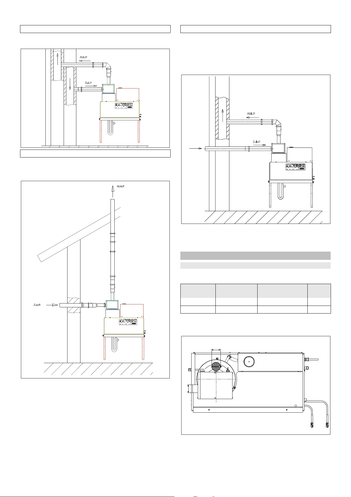
Typ C43
Ø82
Ø75
Gasgerät mit Verbrennungsluftzuführung und Abgasführung zum
Anschluss an ein Luft-Abgas-System.
Typ C53
Gasgerät mit getrennter Verbrennungsluftzuführung und Abgasführung. Die Mündungen befinden sich in unterschiedlichen
Druckbereichen.
Typ C63
Die Verbrennungsluft wird über ein geschlossenes System aus
dem Freien entnommen. Das Abgas ist in einem Schornstein zu
führen.
Voraussetzung ist, dass der Schornstein für den Anschluss von
Brennwertgeräten geeignet ist (z.B. indem der Schornstein durch
Einziehen eines Edelstahlrohres saniert wurde).
Hinweis: Um die vorgeschriebenen Verbrennungswerte zu erreichen, muss der bei den Technischen Daten angegebene Kaminzug eingehalten werden.
Der Kamin muss überdruckgeeignet sein.
Hinweis: Um die vorgeschriebenen Verbrennungswerte zu erreichen, muss der bei den Technischen Daten angegebene Kaminzug eingehalten werden.
Abgassysteme für stationäre Hochdruckreiniger
Abgasnenndurchmesser
Die Abgasnenndurchmesser sind nach EN 13384-1 ermittelt und
gelten für folgende Anwendungsfälle:
Kärcher HDS Abgasdurch-
messer
< 74 kW DN 150 2 m 10 m
> 74 kW DN 200 2 m 10 m
Die ermittelten Durchmesser gelten inkl. einer Umlenkung 90° in
der Verbindungsleitung. Für jede weitere Umlenkung müssen 2,5
m Aufbauhöhe abgezogen werden.
Länge der Verbindungsleitung
Höhe
- 15
17DE
Page 18

Wesentliche Anforderungen
Abgasleitungen müssen gereinigt und auf ihren freien Querschnitt geprüft werden können.
– Für Anlagen mit Bauhöhen im senkrechten Abschnitt von
max. 15 m und einem Leitungsdurchmesser von 150 mm genügt eine Reinigungs- bzw. Inspektionsöffnung im Aufstellraum der Feuerstätte.
– Für Anlagen mit einem Abgasdurchmesser von 200 mm ge-
nügt ebenfalls bis zu einer max. Höhe von 4 m eine untere
Reinigungsmöglichkeit.
– Größere Bauhöhen müssen von der Mündung oder einer Zwi-
schenreinigung im oberen Teil der Abgasanlage aus über-
prüft werden können.
Anfallendes Kondensat kann im unteren Teil der Abgasanlage an
der Kondensatschale aufgefangen und gemäß ATV-Merkblatt
M251 abgeleitet werden.
Maximale Montagehöhen und Abstände
– Zur Fixierung des Abgassystems sind im Abstand von jeweils
2 m Spannbänder an der Wand anzudübeln. Der Verstellbe-
reich der Halterungen beträgt 50-90 mm, um Unebenheiten
ausgleichen zu können.
– Das freistehende Ende der Abgasanlage oberhalb der letzten
Befestigung darf max. 2 m betragen. Größere Kragarmenden
dürfen nur in Kombination mit statisch geprüften Sonderbau-
teilen realisiert werden.
Abstände zu brennbaren Baustoffen
– Bei vertikaler und horizontaler Installation beträgt der Ab-
stand zu brennbaren Baustoffen generell 30 mm frei hinterlüf-
tet.
– Bei der Durchdringung von Wänden oder Decken ist der Ab-
stand auf 50 mm zu vergrößern. Der Spalt darf mit Mineral-
wolle lose gestopft werden.
Auslegungsdiagramm
Auslegungsdiagramm Abgassysteme
Wirksame Höhe in m 4 5 6 7 8 9 10
Durchmesser des Abgassys-
tems in mm
200 200 200 200 150 150 150
Kondensatabfluss
Die Kondensatleitung muss direkt am Kondensatanschluss siphoniert werden. Die Siphonhöhe muss 30 cm betragen. Das Siphon ist im Lieferumfang enthalten. Die Kondensatleitung darf
keine feste Verbindung mit der Kanalisation haben. Das Kondensat muss frei in einen Trichter oder Neutralisationsbehälter auslaufen können.
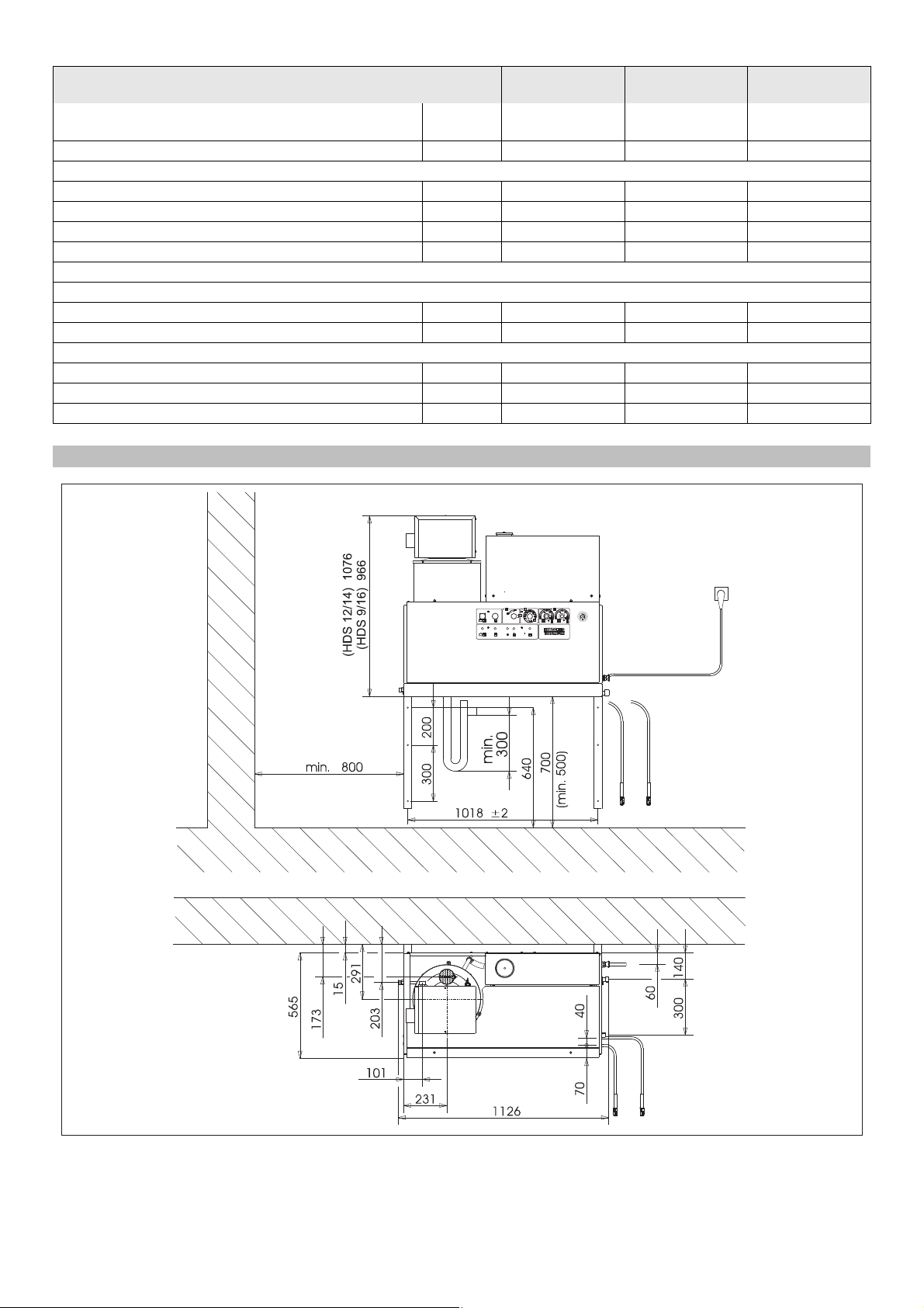
Wandmontage
– Vor der Montage ist die Wand auf Tragfähigkeit hin zu prüfen.
Das mitgelieferte Befestigungsmaterial ist für Beton geeignet.
Für Hohlraumbaustein-, Ziegelbaustein- und Gasbetonwän-
de sind geeignete Dübel und Schrauben zu verwenden, z. B.
Injektionsanker (Bohrbild siehe Maßblatt).
– Bild 3 - Pos. 19 und 25
Das Gerät darf nicht starr mit dem Wasserleitungs- oder dem
Hochdruckrohrleitungsnetz verbunden werden. Die Verbin-
dungsschläuche sind unbedingt zu montieren.
– Bild 3 - A
Zwischen dem Wasserleitungsnetz und dem Verbindungs-
schlauch ist ein Absperrhahn vorzusehen.
Montage der Hochdruckleitungen
Bei der Montage der Hochdruckleitungen sind die jeweiligen nationalen Vorschriften des Gesetzgebers zu beachten.
– Der Druckabfall in der Rohrleitung muss unter 1,5 MPa lie-
gen.
– Die fertige Rohrleitung muss mit 32 MPa geprüft werden.
– Die Isolation der Rohrleitung muss bis 100 °C temperaturbe-
ständig sein.
Reinigungsmittelbehälter aufstellen
Bild 3 - Pos. 20
Die Behälter sind so aufzustellen, dass sich der untere Niveauspiegel des Reinigungsmittels nicht mehr als 1,5 m unter dem
Geräteboden und der obere Niveauspiegel nicht über dem Geräteboden befindet.
Wasserversorgung
Bild 3 - B und Pos. 19
Wassereingang mit einem passenden Wasserschlauch an
das Wasserleitungsnetz anschließen.
– Die Leistung der Wasserversorgung muss mindestens 1300
l/h bei mindestens 0,1 MPa betragen.
– Die Wassertemperatur muss unter 30 °C liegen.
Elektrischer Anschluss
ACHTUNG
Die maximal zulässige Netzimpedanz am elektrischen Anschlusspunkt (siehe Technische Daten) darf nicht überschritten
werden. Bei Unklarheiten bezüglich der an Ihrem Anschlusspunkt vorliegenden Netzimpedanz setzen Sie sich bitte mit Ihrem
Energieversorgungsunternehmen in Verbindung.
Hinweis: Einschaltvorgänge erzeugen kurzzeitig Spannungabsenkungen. Bei ungünstigen Netzbedingungen können Beeinträchtigungen anderer Geräte auftreten.
– Anschlusswerte siehe Technische Daten und Typenschild.
– Der elektrische Anschluss muss von einem Elektroinstalla-
teur ausgeführt werden und IEC 60364-1 entsprechen.
– Stromführende Teile, Kabel und Geräte im Arbeitsbereich
müssen in einwandfreiem Zustand strahlwassergeschützt
sein.
GEFAHR
Zur Vermeidung von Elektrounfällen empfehlen wir, Steckdosen
mit vorgeschaltetem Fehlerstrom-Schutzschalter (max. 30 mA
Nennauslöse-Stromstärke) zu benutzen.
Fest installierter elektrischer Anschluss
Elektrischen Anschluss herstellen.
Für das Abschalten des stationären Hochdruckreinigers ist ein
abschließbarer Hauptschalter (Bild 3 - Pos. 6) an ungefährdeter
Stelle leicht zugänglich anzubringen.
Die Kontaktöffnungsweite des Hauptschalters muss mindestens
3 mm betragen.
Elektrischer Anschluss mit Stecker/Steckdose
Cekon-Stecker an Anschlusskabel des Gerätes montieren.
Cekon-Stecker in Steckdose stecken.
Für das Abschalten des stationären Hochdruckreinigers muss
der Cekon-Stecker zur Netztrennung leicht zugänglich sein.
Erstinbetriebnahme
Das Gerät ist werkseitig als Erdgas-Gerät auf die Gasart G 20
und als Flüssiggas-Gerät auf G 31 eingestellt. Bei Umstellung
des Erdgas-Gerätes auf G 25 oder andere (siehe Typenschild)
Erdgase oder des Flüssiggas-Gerätes auf G 30 oder andere
(siehe Typenschild) Flüssiggase, sind beim Erdgas-Gerät die
Erdgas-Abgaswerte und beim Flüssiggas-Gerät die FlüssiggasWerte gemäß Service-Information einzustellen.
18 DE
- 16
Page 19
Das beiliegende Leerschild wird mit der neu eingestellten Gasart
abc d
b
c
a
a
87654321
S2
min.
max.
beschriftet und im Anschriftenfeld auf der rechten Geräteseite
angebracht. Gleichzeitig muss das dort ab Werk angebrachte
Schild mit Angabe G 20 (Erdgas-Gerät) oder G 31 (FlüssiggasGerät) entfernt werden.
Gasanschluss überprüfen.
ACHTUNG
Beschädigungsgefahr des Gerätes durch Überhitzung.
Siphon an Kesselboden anschließen und mit Wasser befüllen.
Kessel über Kaminöffnung mit 4 Liter Wasser füllen.
Vor dem ersten Gebrauch die Spitze des Deckels vom Ölbe-
hälter auf der Wasserpumpe abschneiden.
Maßnahmen vor Inbetriebnahme
Bild 3 - Pos. 14
Hinweis: Das EASY!Lock-System verbindet Komponenten
durch ein Schnellgewinde mit nur einer Umdrehung schnell und
sicher.
Hochdruckschlauch mit Handspritzpistole und Strahlrohr ver-
binden und am Hochdruckausgang des Gerätes oder am
Hochdruckrohrleitungsnetz anschließen.
Drehpotentiometer (a) je nach Wasserhärte einstellen. Aus
der Tabelle kann die richtige Einstellung entnommen werden.
Beispiel:
Für eine Wasserhärte von 15 °dH Skalenwert 6 am Drehpotentiometer einstellen. Daraus ergibt sich eine Pausenzeit von 31 Sekunden, d.h. alle 31 Sekunden öffnet kurz das Magnetventil.
Wasserhärte (°dH) 5 10 15 20 25
Skala am Drehpotentiome-
ter
Pausenzeit (Sekunden) 50 40 31 22 16
87654,5
Verstellen der Betriebsbereitschaftszeit
Die Einstellung der Betriebsbereitschaftszeit erfolgt auf der größeren Platine an der linken Seitenwand des Elektroschrankes.
Düsenmundstück (b) mit Überwurfmutter (a) am Strahlrohr
(d) befestigen. Darauf achten, dass der Dichtring (c) sauber
in der Nut liegt.
Schutz vor Verkalkung
Feder (c) von der Deckelstütze (b) des Enthärterbehälters (a)
entfernen.
Behälter mit Kärcher-Enthärterflüssigkeit RM 110 (Best.-Nr.
2.780-001) füllen.
GEFAHR
Gefährliche elektrische Spannung! Einstellung darf nur durch
eine Elektro-Fachkraft erfolgen.
Die örtliche Wasserhärte ermitteln:
– Über das örtliche Versorgungsunternehmen,
– mit einem Härteprüfgerät (Best.-Nr. 6.768-004).
Gerätehaube abnehmen.
Schaltkasten am Bedienfeld öffnen.
Die Betriebsbereitschaftszeit ist werkseitig auf die Minimalzeit
von 2 Minuten eingestellt und kann bis zur Maximalzeit von 8 Minuten erhöht werden.
- 17
19DE
Page 20
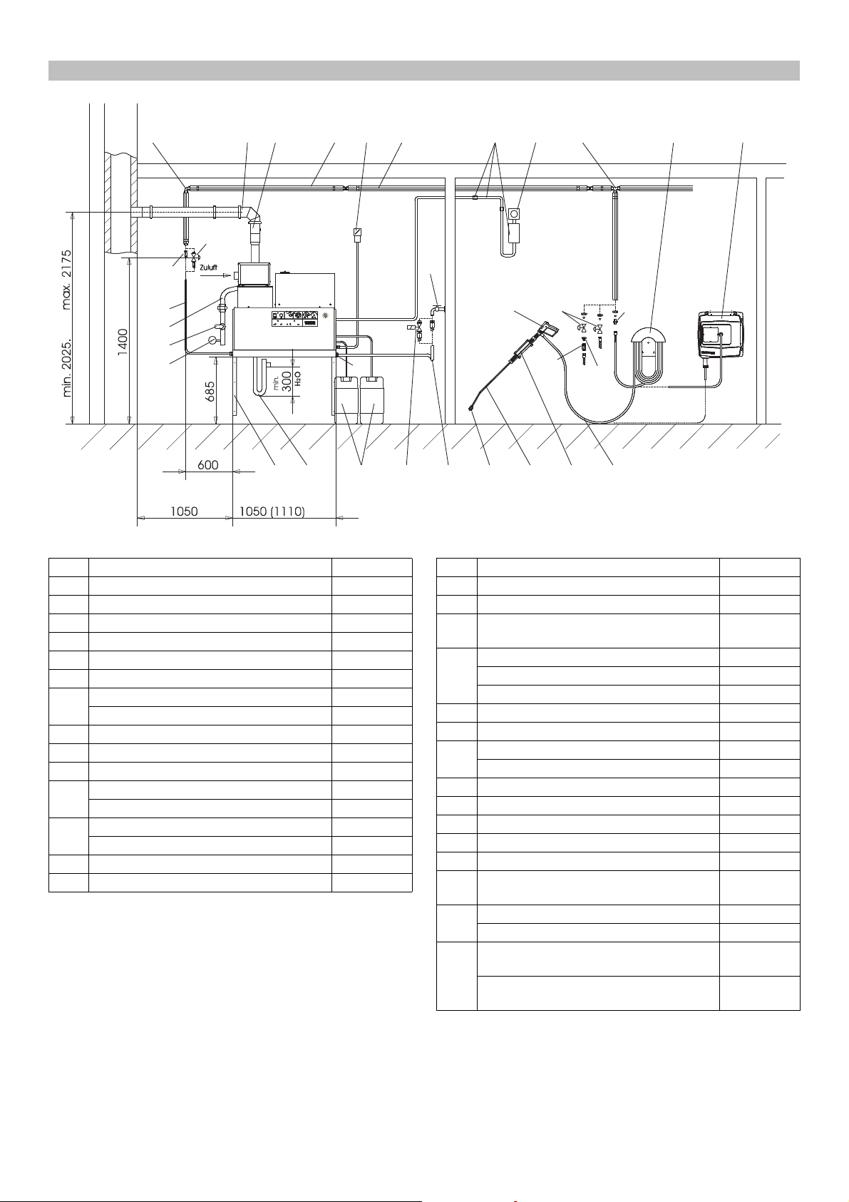
Installationsmaterial
1 23567 8910 1213
A
15 11b 11a
11c
11a
25
21
22
23
11b
24 4 20 19a 19 18 17 16 14
11d
B
Bild 3
Pos. Installationsmaterial Bestell-Nr.
1 Winkelverschraubung 6.386-356
2 Abgasleitungskit, waagerecht, 150 mm 6.526-231
3 Abgasleitungskit, senkrecht, 150 mm 6.526-232
4 Teilesatz Siphon 2.640-422
5 Wärmeisolation 6.286-114
6 Hauptschalter 6.631-455
7 Rohrleitungssatz, Stahl verzinkt 2.420-004
Rohrleitungssatz, Edelstahl 2.420-006
8 Teilesatz Fernsteuerung 2.744-008
9 Teilesatz Not-Aus-Schalter 2.744-002
10 T-Verschraubung 6.386-269
11a Anschlussstutzen, Messing 2.638-180
Anschlussstutzen, Edelstahl 2.638-181
11b Absperrhahn NW 8, Stahl verzinkt 4.580-144
Absperrhahn NW 8, Edelstahl 4.580-163
11c Schnellkupplungsfestteil 6.463-025
11d Schnellkupplungslosteil 6.463-023
Pos. Installationsmaterial Bestell-Nr.
12 Schlauchhalter 2.042-001
13 Schlauchtrommel 2.637-238
14 Hochdruckschlauch EASY!Lock 10 m
(Anschlüsse 2x TR)
15 Handspritzpistole EASY!Force 4.118-005
Drehregler HDS 9/16-4 4.118-008
Drehregler HDS 12/14-4 4.118-009
16 Strahlrohrhalter 2.042-002
17 Strahlrohr EASY!Lock 4.112-012
18 Düsenmundstück HDS 9/16-4 2.113-026
Düsenmundstück HDS 12/14-4 2.113-015
19 Wasserschlauch 4.440-282
19a Magnetventil Wasserzulauf 4.743-011
20 Reinigungsmittel-Tank, 60 l 5.070-078
21 Gasschlauch R1“ 6.388-228
22 Gas-Absperrhahn R1“ 6.412-389
23 Manometer, Gas (Achtung! Abschlussven-
til bauseits vorsehen.)
24 Teilesatz Wandkonsole 2.053-005
Teilesatz Bodengestell 2.210-008
25 Hochdruckschlauch EASY!Lock 1,5 m
(Anschlüsse TR - M22x1,5)
Hochdruckschlauch EASY!Lock 1,5 m
(Anschlüsse 2x TR)
* Adapter TR - M22x1,5 (4.111-030) erforderlich
6.110-038 *
6.412-059
6.110-068
6.110-024 *
20 DE
- 18
Page 21

EU-Konformitätserklärung
Chairman of the Board of Management
Director Regulatory Affairs & Certification
Hiermit erklären wir, dass die nachfolgend bezeichnete Maschine
aufgrund ihrer Konzipierung und Bauart sowie in der von uns in
Verkehr gebrachten Ausführung den einschlägigen grundlegenden Sicherheits- und Gesundheitsanforderungen der EU-Richtlinien entspricht. Bei einer nicht mit uns abgestimmten Änderung
der Maschine verliert diese Erklärung ihre Gültigkeit.
Produkt: Hochdruckreiniger
Typ: 1.251-xxx
Einschlägige EU-Richtlinien
(EU) 2016/426
2006/42/EG (+2009/127/EG)
2014/30/EU
Angewandte harmonisierte Normen
EN 55014–1: 2006+A1: 2009+A2: 2011
EN 55014–2: 2015
EN 60335–1
EN 60335–2–79
EN 62233: 2008
EN 61000–3–2: 2014
HDS 12/14:
EN 61000–3–3: 2013
HDS 9/16:
EN 61000–3–11: 2000
Angewandte Spezifikationen:
QA 195 (nicht LPG)
Name der benannten Stelle:
für (EU) 2016/426
Kiwa Nederland B.V.
Sir Winston Churchill-laan 273
2288 EA Rijswijk
Kenn-Nr. 0063
5.957-648
Die Unterzeichnenden handeln im Auftrag und mit Vollmacht des
Vorstands.
Dokumentationsbevollmächtigter:
S. Reiser
Alfred Kärcher SE & Co. KG
Alfred-Kärcher-Straße 28-40
71364 Winnenden (Germany)
Tel.: +49 7195 14-0
Fax: +49 7195 14-2212
Winnenden, 2018/10/01
Garantie
In jedem Land gelten die von unserer zuständigen Vertriebsgesellschaft herausgegebenen Garantiebedingungen. Etwaige Störungen an Ihrem Gerät beseitigen wir innerhalb der Garantiefrist
kostenlos, sofern ein Material- oder Herstellungsfehler die Ursache sein sollte. Im Garantiefall wenden Sie sich bitte mit Kaufbeleg an Ihren Händler oder die nächste autorisierte Kundendienststelle.
- 19
21DE
Page 22

Kundendienst
Anlagentyp: Herstell-Nr.: Inbetriebnahme am:
Prüfung durchgeführt am:
Befund:
Unterschrift
Prüfung durchgeführt am:
Befund:
Unterschrift
Prüfung durchgeführt am:
Befund:
Unterschrift
Prüfung durchgeführt am:
Befund:
Unterschrift
22 DE
- 20
Page 23
Please read and comply with these original instruc-
tions prior to the initial operation of your appliance and
store them for later use or subsequent owners.
– Before first start-up it is definitely necessary to read the safety
indications Nr. 5.956-309.0!
– In case of transport damage inform vendor immediately.
Contents
Environmental protection . . . . . EN 1
Danger or hazard levels. . . . . . EN 1
Symbols on the machine . . . . . EN 1
General notes on safety. . . . . . EN 1
Proper use . . . . . . . . . . . . . . . . EN 2
Function . . . . . . . . . . . . . . . . . . EN 2
Safety Devices. . . . . . . . . . . . . EN 2
Device elements . . . . . . . . . . . EN 3
Start up . . . . . . . . . . . . . . . . . . EN 4
Operation . . . . . . . . . . . . . . . . . EN 4
Shutting down . . . . . . . . . . . . . EN 6
Shutdown. . . . . . . . . . . . . . . . . EN 6
Storage . . . . . . . . . . . . . . . . . . EN 6
Transport . . . . . . . . . . . . . . . . . EN 6
Technical specifications. . . . . . EN 7
Care and maintenance . . . . . . EN 9
Troubleshooting . . . . . . . . . . . . EN 11
Accessories . . . . . . . . . . . . . . . EN 13
Installing the plant . . . . . . . . . . EN 14
EU Declaration of Conformity . EN 19
Warranty . . . . . . . . . . . . . . . . . EN 19
Customer Service . . . . . . . . . . EN 20
Environmental protection
The packaging material can be recycled. Please do
not throw the packaging material into household
waste; please send it for recycling.
Old appliances contain valuable materials that can be
recycled; these should be sent for recycling. Batteries,
oil, and similar substances must not enter the environment. Please dispose of your old appliances using appropriate collection systems.
Please do not release engine oil, fuel oil, diesel and petrol into
the environment Protect the ground and dispose of used oil in an
environmentally-clean manner.
Kärcher detergents are easy-to-dispose. This means that the
functioning of an oil separator is not hampered. Please find a list
of recommended detergents in the chapter "Accessories".
Notes about the ingredients (REACH)
You will find current information about the ingredients at:
www.kaercher.com/REACH
Danger or hazard levels
DANGER
Pointer to immediate danger, which leads to severe injuries or
death.
몇 WARNING
Pointer to a possibly dangerous situation, which can lead to severe injuries or death.
몇 CAUTION
Pointer to a possibly dangerous situation, which can lead to minor
injuries.
ATTENTION
Pointer to a possibly dangerous situation, which can lead to property damage.
Symbols on the machine
High-pressure jets can be dangerous if improperly
used. The jet may not be directed at persons, animals,
live electrical equipment or at the appliance itself.
General notes on safety
– Please follow the national rules and regulations for fluid spray
jets of the respective country.
– Please follow the national rules and regulations for accident
prevention of the respective country. Fluid spray jets must be
tested regularly and the results of these tests must be documented in writing.
– The heating appliance of the machine is an ignition plant. All
national laws and regulations about heating systems must
also be followed.
– If the plant is operated in rooms, then there should be ade-
quate measures for safely diverting the exhaust gases out of
the room (smoke gas pipes without draught interceptors).
Further, there must also be adequate supply of fresh air.
– Please follow the safety instructions which are attached to the
used detergents (normally on the packing label).
– The appliance/accessories must not be modified.
Statutory Requirements, Guidelines and Rules
Before installing the machine, it is necessary to get the approval
of the gas supply company and the local chief chimney cleaner.
The statutory requirements of civil engineering laws, trade laws
and emission control norms must be followed at the time of installation. We wish to bring to your notice the following statutory regulations, guidelines and standards:
– The device may only be installed by a specialized company
according to the national regulations.
– All national laws and regulations about installation of electri-
cal appliances must also be followed.
– All national laws and regulations about installation of gas ap-
pliances must also be followed.
– Installation of gas pipes - especially the gas connections to
the machine - should only be done by a technical company
that has been approved by the Industrial Association for Gas
and Water Installations.
– Only Customer Service engineers trained by Kärcher may
perform settings and carry out maintenance tasks and repairs.
– The local guidelines must be followed while installing the
chimney.
- 1
23EN
Page 24
Work-stations
The work station is located at the operating field. Depending on
the plant installation, other work-stations are located at the accessories (spraying units) that are connected to the feeder
points.
Personal safety gear
Wear ear plugs to protect your ears against
hearing loss while cleaning parts that produce
high sound levels.
– Wear protective clothing and safety goggles to protect against
splash back containing water or dirt.
Proper use
The machine is used for removing dirt from surfaces using a freeflowing water jet. It is mainly used for cleaning machines, vehicles
and facades.
DANGER
Risk of injury! Follow the respective safety regulations upon employment at gas stations or other dangerous areas.
Please do not let mineral oil contaminated waste water reach
soil, water or the sewage system. Perform engine cleaning and
bottom cleaning therefore only on specified places with an oil
trap.
Quality requirements for water:
ATTENTION
Only clean water may be used as high pressure medium. Impurities will lead to increased wear and tear or formation of deposits
in the appliance and accessories.
If recycled water is used, the following limit values must not be
exceeded.
pH value 6,5...9,5
electrical conductivity * Conductivity fresh water
+1200 µS/cm
settleable solids ** < 0,5 mg/l
total suspended solids *** < 50 mg/l
Hydrocarbons < 20 mg/l
Chloride < 300 mg/l
Sulphate < 240 mg/l
Calcium < 200 mg/l
Total hardness < 28 °dH
< 50 °TH
< 500 ppm (mg CaCO
Iron < 0,5 mg/l
Manganese < 0,05 mg/l
Copper < 2 mg/l
Active chloride < 0,3 mg/l
free of bad odours
* Maximum total 2000 µS/cm
** Test volume 1 l, settling time 30 min
*** no abrasive substances
/l)
3
Function
– Cold water reaches the swimmer tank via the engine cooling
hose and from there it reaches the outer jacket of the continuous heater and then the suction side of the high pressure
pump. The water softening agent is added in the swimmer
tank. The pump transports the water and the sucked detergent through the continuous heater. The proportion of detergent in the water can be adjusted using the dosing valve. The
continuous heater is heated by a gas heater.
– The high pressure outlet is connected to a high pressure net-
work existing in the building. The hand-spray gun is connected to the feeder points of this network using a high pressure
hose.
Safety Devices
Safety devices serve for the protection of the user and must not
be put out of operation or bypassed with respect to their function.
Safety mechanism against lack of water in swimmer
tank
The safety mechanism against lack of water prevents the high
pressure pump from being switched on when there is no water.
Safety mechanism against lack of water in safety
block
The safety mechanism against lack of water prevents the heater
from over-heating when there is no water. The burner operates
only when there is adequate water supply.
Pressure switch
The pressure switch switches off the machine when the working
pressure is exceeded. Do not change the setting.
Safety valve
The safety valve opens when there is a problem in the pressure
switch. This valve is set and sealed in the factory. Do not change
the setting.
Flame monitoring
In case of fuel shortage or problems with the burner, the flame
monitor switches off the burner. The indicator lamp Burner failure
(E) glows.
Over-current protection
If the burner engine is blocked, the switch for protection against
over-current gets released. The engine of the high pressure
pump is protected through an engine protection switch and a
winding protection switch.
Exhaust thermostat
The exhaust thermostat is triggered when the exhaust temperature exceeds 320 °C. The indicator lamp exhaust gas thermostat
(K) glows.
Temperature controller
The maximum temperature controller in the boiler floor (> 80 °C)
and the water outlet (> 110 °C) will get triggered and the indicator
lamp for boiler interruption (E) will glow.
Exhaust pressure switch
The exhaust pressure switch will switch off the burner when the
exhaust gas system has reached abnormally high counter-pressure levels, for e.g. when there is a blockade.
Pressure release in the high pressure system
When the machine is switched off using the hand-spray gun, a
solenoid valve installed in the high pressure system opens when
the operations stand-by time has elapsed; this causes the pressure to fall.
Safety catch
The safety catch on the trigger gun prevents the appliance from
being switched on unintentionally.
24 EN
- 2
Page 25

Device elements
12
13
14
151617
4
8
1 11 2 9
10
6 7
3
5
Figure 1
1 Burner
2 Manometer
3 Fresh water inlet with sieve
4 High-pressure outlet EASY!Lock
5 Gas connection
6 Detergent suck hose I
7 Detergent suck hose II (optional)
8 Softener container
9 Power supply
10 Float tank
11 Operating field
12 Safety lever
13 Trigger
14 Safety latch of the hand spray gun
15 Trigger gun EASY!Force
16 Pressure/ quantity regulation at the hand spray gun
17 Spray lance EASY!Lock
Operating field
Figure 2
A Power switch
B Temperature controller
C Dosage valve I for detergent
D Dosage valve II for detergent (optional)
E Indicator lamp burner failure
F “Ready for use” indicator lamp
G Indicator lamp for engine over-heating
H Indicator lamp for protection against calcification
I Unlocking key for gas relay
J Unlocking key for exhaust gas thermostat
K Indicator lamp for exhaust gas thermostat
- 3
25EN
Page 26
Start up
!
몇 WARNING
Risk of injury! Appliance, accessories, supply lines and connections must be in fault-free condition. If they are not in a perfect
state then the appliance must not be used.
Power connection
– For connection values, see technical data and type plate.
– The electrical connections must be done by an electrician ac-
cording to IEC 60364-1.
Operation
DANGER
Danger of explosion! Do not spray flammable liquids.
DANGER
Risk of injury! Never use the appliance without the spray lance attached. Check and ensure proper fitting of the spray lance prior
to each use. The screw connection of the spray lance must be finger-tight.
DANGER
Risk of injury! Hold the hand spray gun and the spray pipe firmly
with both hands.
DANGER
Risk of injury! The trigger and safety lever may not be locked during the operation.
DANGER
Risk of injury! Contact Customer Service if the safety lever is
damaged.
Safety instructions
The operator must use the appliance correctly. When working
with the appliance, he must consider the local conditions and pay
due care and attention to other persons, in particular children,
who are nearby.
Never leave the appliance unattended when it is in operation.
DANGER
– Danger of scalding by hot water! Do not direct the water jet on
persons or animals.
– Risk of burns on account of hot surfaces! Do not touch unin-
sulated pipes and hoses when hot water operations are on.
Hold the jet pipe only at the handles. Do not touch the exhaust
holder of the continuous heater.
– Risk of poisoning or itching on account of detergent! Follow
the given instructions for using detergents. Store detergents
safely and protect them against access by unauthorised persons.
DANGER
Risk to life on account of electric shock! Do not direct the water
jet on the following equipment:
– Electrical appliances and plants,
– the unit itself,
– all electricity-carrying parts in the working area.
There is a recoil pressure arising from the water jet that comes
out from the spray pipe. The angular spray pipe brings about an
upward force.
DANGER
– Risk of injury! The recoil pressure of the spray lance can
throw you off balance. You may fall. The spray lance can fly
off and cause damage to persons. Search for a secure place
to stand and hold the gun firmly.
– The jet must not be directed at other persons or directed by
the user at him/herself to clean clothing or footwear.
– Risk of injury from parts flying off! Flying-off fragments or ob-
jects can injure people or animals. Never direct the water jet
on fragile or loose objects.
– Risk of accident on account of damage! Clean tyres and
valves from a minimum distance of 30 cm.
몇 WARNING
Danger from substances that are harmful to health! Do not spray
the following materials as they can swirl up substances that are
harmful to health:
– Materials containing asbestos,
– Materials that could contain substances harmful to health.
DANGER
– Risk of injury on account of the emanating water jet that could
be hot! Only original Kaercher high pressure hoses are optimally suited for the plant. No guarantee can be given if you
use any other hoses.
– Detergents can prove to be a health hazard! If any detergents
are added, the water let out of the plant is not of potable quality.
– Risk of hearing impairment while working on noise-making
parts! If so, wear ear plugs.
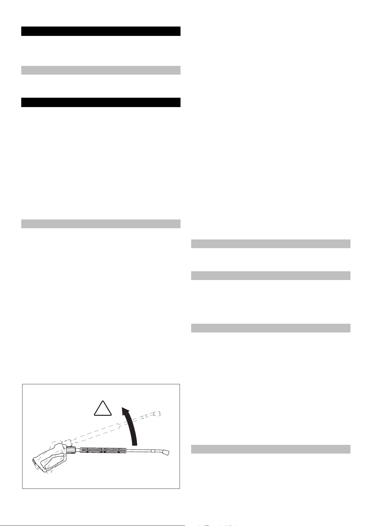
Opening/closing the trigger gun
To open the trigger gun: Actuate the safety lever and trigger.
To close the hand spray gun: Release the safety lever and
trigger.
Replace the nozzle
DANGER
Risk of injury! Switch the appliance off prior to replacing nozzle
and activate hand spray gun until device is pressureless.
Secure the trigger gun. To do so, push the safety catch to-
wards the front.
Replacing the nozzle.
Making the plant ready for operations
DANGER
Risk of injury on account of the emanating water jet that could be
hot!
DANGER
Check the high pressure hose for damage before every use.
Please arrange for the immediate replacement of a damaged
high pressure hose.
Check high pressure hose, pipe connections, fittings and wa-
ter jet for damage every time before use.
Check hose coupling to ensure that it sits firmly and is leak-
proof.
ATTENTION
Risk of damage on account of dry running.
Check filling level of the detergent container and refill if re-
quired.
Check softener fluid level and refill if necessary.
Switch-off in case of emergency
Turn the appliance switch (A) to "0".
Shut off water supply.
Activate trigger gun until device is pressure-less.
Close the gas inlet.
26 EN
- 4
Page 27
Set working pressure and flow rate
R
Appliance setting
Turning the quantity regulation valve in clock-wise direction
will result in higher working pressure and larger volume.
Turning the quantity regulation valve in an anti-clockwise di-
rection will result in lower working pressure and smaller quantities.
Adjusting the pressure/quantity regulation of the trigger gun (option)
DANGER
Risk of injury! When adjusting the pressure/quantity regulation,
make sure that the screw connection of the spray lance does not
become loose.
Turning the water quantity regulator to the right gives more
water flow and higher working pressure.
Turning the water quantity regulator to the left gives lesser
water flow and lower working pressure.
Operating with cold water
Open the water supply.
Operating with hot water
DANGER
Scalding danger!
ATTENTION
Hot water operations without fuel will cause damage to the fuel
pump. Ensure adequate fuel supply before starting hot water operations.
If required, the burner can also be turned on subsequently.
Symbol "Burner on"
Turn the appliance switch (A) to "Burner on".
Set the desired water temperature on the thermostat (B).
Maximum temperature is 98 °C.
Operations stand-by
– If the trigger gun is closed during operation, the appliance will
switch off.
– The appliance will automatically start again when you open
the gun again within the stand-by period (2 ... 8 minutes).
– If the stand-by period is exceeded, the safety time mecha-
nism switches off the pump and the burner. The indicator
lamp Operations Stand-by (F) goes off.
– To restart the appliance, set the appliance switch to "0" and
then switch on the appliance again. If the appliance is operated using remote control, the appliance can be restarted by using the corresponding switch of the remote control device.
Selecting the nozzle
– Vehicle tyres are only cleaned using the flat spray nozzle
((25°) from a minimum spraying distance of 30 cm. The round
spray should never be used to clean tyres.
The following nozzles can be selected for all other tasks:
Dirt Nozzle Spray an-
gle
strong 00060 0° 5.765-240 16 46
medium 25060 25° 5.765-027
light 40060 40° 5.130-087
strong 00080 0° 5.765-243 14 55
medium 25080 25° 5.765-061
light 40080 40° 5.765-221
Use the following nozzles if the pipe length is more than 20 m or
for more than 2 x 10 m high pressure hose NW8:
Dirt Nozzle Spray an-
gle
strong 0075 0° 5.765-242 10 37
medium 2575 25° 5.765-057
light 4075 40° 5.765-220
Part no.: Pressure
HDS 9/16
HDS 12/14
Part no.: Pressure
HDS 9/16
Recoil [N]
[MPa]
Recoil [N]
[MPa]
Symbol "Engine on"
Release the trigger gun. To do so, push the safety catch to-
wards the back.
Open the trigger gun and set the appliance switch (A) to "1"
(motor on).
The indicator lamp for operational readiness (F) shows that
the appliance is in stand-by mode and ready to be operated.
- 5
27EN
Page 28
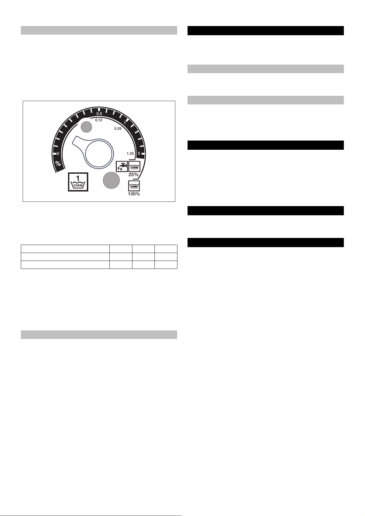
Detergent dosing
– Detergents simplify the cleaning task. They are sucked in
from an external detergent tank.
– The basic model of the appliance is equipped with a dosing
valve (C). A second dosing device (dosing valve D) can also
be procured as special accessory. It is then possible to use
two different detergents.
– The dosing quantity is set at the detergent dosing valves (C
or D) at the operating panel. The set value corresponds to the
percentage share of the detergent.
– The outer scale is applicable while using undiluted detergents
(100% CHEM).
– The inner scale is appliance while using 1 +3 pre-diluted de-
tergents (25 % CHEM + 75 % water).
The following table gives the detergent consumption for the values on the outer scale:
Position 0.5 1 8
Detergent quantity [l/h] 14...15 22...24 50
Detergent concentration [%] 1.5 2.5 > 5
The exact dosing depends on:
– Viscosity of the detergent
– Suction height
– Flow resistance of the high pressure pipe
If an exact dosing is required, then measure the detergent quantity that is sucked in (for e.g. by sucking in from a measurement
beaker).
Note: For list of recommended detergents refer the chapter "Accessories".
Refilling the softener
ATTENTION
There can be calcium deposits in the continuous heater if you use
the appliance without softeners.
If the softener tank is empty, the indicator lamp for protection
against calcification (H) begins to glow.
Figure 1 - Pos. 8
Refill the softener tank with softener liquid RM 110 (2.780-
001).
Shutting down
DANGER
Danger of scalding by hot water. After operation with hot water,
the device must be operated with open end handgun with cold
water for at least two minutes.
After operation with detergent
If operating with hot water, set the thermostat (B) to the lowest
temperature.
Use the appliance for at least 30 seconds without detergent.
Turn off the appliance
Turn the appliance switch (A) to "0".
Shut off water supply.
Activate trigger gun until device is pressure-less.
Secure the hand spray gun using the safety catch so that it
doesn't open accidentally.
Shutdown
If the machine is not to be used for a longer period or if it is not
possible to save it in a frost-free environment, then you must take
the following measures (see chapter "Maintenance and care"):
Drain water.
Flush device with anti-freeze agent.
Switch off the main switch and secure it or unplug the Cekon
plug.
Close the gas inlet.
Storage
몇 CAUTION
Risk of injury and damage! Note the weight of the appliance in
case of storage.
Transport
ATTENTION
Protect the trigger from damage during transport.
몇 CAUTION
Risk of injury and damage! Observe the weight of the appliance
when you transport it.
When transporting in vehicles, secure the appliance accord-
ing to the guidelines from slipping and tipping over.
28 EN
- 6
Page 29

Technical specifications
HDS 9/16-4 ST
Gas
HDS 12/14-4 ST
Gas
HDS 12/14-4 ST
Gas LPG
1.251-900 1.251-901 1.251-902
Performance data
Operating pressure of water (using standard nozzle) MPa (bar) 16 (160) 14 (140) 14 (140)
Max. excess operating pressure (safety valve) MPa (bar) 18.5 (185) 18.5 (185) 18.5 (185)
Water flow (can be regulated in a phase-less manner) l/h (l/min) 500-1000 (8.3-
600-1200 (10-20) 600-1200 (10-20)
16.6)
Suction of detergent (can be regulated in a phaseless man-
l/h (l/min) 0-50 (0-0.8) 0-60 (0-1) 0-60 (0-1)
ner)
Water connection
Min. feed volume l/h (l/min) 1100 (18.3) 1300 (21.7) 1300 (21.7)
Feed pressure (min.) MPa (bar) 0.1 (1) 0.1 (1) 0.1 (1)
Max. feed pressure MPa (bar) 0.6 (6) 0.6 (6) 0.6 (6)
Electrical connection
Current type -- 3N~ 3N~ 3N~
Frequency Hz 50 50 50
Voltage V 380-420 380-420 380-420
Connected load kW 6.4 7.5 7.5
Electrical protection (slow) A 16 20 20
Type of protection -- IPX5 IPX5 IPX5
Protective class -- I I I
Maximum allowed net impedance Ohm (0.381+j 0.238) -- -Power supply mm
2
5 x 2.5 5 x 2.5 5 x 2.5
Temperature
Max. feed temperature °C 30 30 30
Max. operating temperature of hot water °C 98 98 98
Max. temperature safety thermostat °C 110 110 110
Temperature increase during maximum water flow °C 60-65 60-65 60-65
Net heating capacity(Hi) kW 70 95 95
Chimney draught kPa 0.01-0.04 0.01-0.04 0.01-0.04
Gas connection values
3
Natural gas E (G 20) m
Natural gas LL (G 25) m
/h 7.2 9.8 --
3
/h 8.2 11.4 -Rated connection pressure (natural gas) kPa 1.8-5 1.8-5 -Propane kg/h -- -- 7.2
Rated connection pressure (Propane) kPa -- -- 5-6
Environment data
Rated utilisation level % 97 97 97
Standard emission factor NO
(natural gas G 25) mg/kWh < 40 < 40 --
X
Standard emission factor CO (natural gas G 25) mg/kWh < 40 < 40 --
Values for chimney dimensions
Suitability for excess pressure (min.) kPa 0.05 0.05 0.05
Draught requirements kPa 0 0 0
Exhaust flow - full load kg/h 130 166 166
(Natural gas) % 9.5 9.5 --
CO
2
(Propane) % -- -- 12
CO
2
Exhaust temperature max./min. °C 190/150 170/130 170/130
Combustion air/ air supply Max. length: 10 n with two 90° arches (min. diameter 100 mm) From the
installation room or fresh outside air - depending on the local regulations.
Condensate drain-out
Condensate drain-out (max.) l/h 4 (via siphon into
the drainage system)
4 (via siphon into
the drainage system)
4 (via siphon into
the drainage sys-
tem)
Connectiing piece DN 40 (HTR) 40 (HTR) 40 (HTR)
Minimum water column, siphon mm 300 300 300
Appliance category Europe -- I 2E (r), I 2ELL, I
2H, I 2L, I2 HE
I 2E (r), I 2ELL, I
2H, I 2L, I2 HE
I 3P
- 7
29EN
Page 30

HDS 9/16-4 ST
Gas
Appliance type -- B23, C33, C43,
C53
HDS 12/14-4 ST
Gas
B23, C33, C43,
C53
HDS 12/14-4 ST
Gas LPG
B23, C33, C43,
C53
CE Product Identification Number -- PIN 0063 BN 3880 PIN 0063 BN 3880 PIN 0063 BN 3880
Dimensions and weights
Length mm 1124 1124 1124
Width mm 558 558 558
Height mm 966 1076 1076
Typical operating weight kg 193.5 209 209
Values determined as per EN 60335-2-79
Noise emission
Sound pressure level L
Uncertainty K
pA
pA
dB(A)747676
dB(A)111
Hand-arm vibration value
Hand spray gun m/s
Spray lance m/s
Uncertainty K m/s
2
2
2
2.2 2.3 2.3
1.8 2.1 2.1
1.0 1.0 1.0
Specifications sheet
30 EN
- 8
Page 31

Care and maintenance
DANGER
Risk of injury! The main switch of the vacuum cleaner is to be switched off or the Cekon plug must be unplugged while carrying out
any repairs or maintenance jobs.
Maintenance schedule
Time Activity Assembly affected Performance of whom
daily Check hand-
spray gun
Check high pressure hoses
Check the connecting line with
mains plug
weekly or after 40
operating hours
monthly or after
200 operating
hours
after 500 - 700 operating hours
half-yearly or after
1000 operating
hours
annual Safety check Entire plant Perform a safety inspection as per the applicable
Check oil level Oil tank at the pump If the oil is milky, it needs to be replaced. Operator
Check oil level Oil tank at the pump Check oil level of the pump. Refill oil if required
Cleaning the
sieve
Check pump High-pressure pump Check the pump for leaks. If the leakage is more
Check for internal deposits
Cleaning the
sieve
Replace Electric igniter, ionisation elec-
Oil change High-pressure pump Drain off oil. Fill in 1 l new oil (Order no. 6.288-
check, clean Entire plant Visual inspection of the plant, check high pres-
Replace the hose Hose to exhaust pushbutton
Hand spray gun Check whether the hand-spray gun closes tightly
without any leaks. Check the protection mechanism against accidental switching. Replace defective hand-spray guns.
Outlets, hoses towards working
machine
Electrical connection with plug/
socket
Sieve in water inlet See section "Clean sieve". Operator
Entire plant Operate the machine using the spray pipe without
Sieve in the water shortage
safeguard
trode
switch
Check hoses to see if there are damages. Replace defect hoses immediately. Danger of accident!
Check the connecting line with mains plug for
damages. If the power cord is damaged, please
arrange immediately for the exchange by an authorized customer service or a skilled electrician.
(Order no. 6.288-016)
than 3 drops per minute, call Customer Service.
the high pressure nozzle. If the operating pressure on the manometer of the machine increases
to more than 3 MPa, then the plant needs to be
decalcified. The same is applicable when an operating pressure of more than 0.7 - 1 MPa is detected while operating the machine without high
pressure pipe (water comes out freely at the high
pressure outlet).
See section "Clean sieve". Operator
Replace electric igniter and/or the ionisation electrode.
016). Check oil level in the oil tank.
sure connections to see that they are not leaking,
check that the over-flow valves are not leaking,
check high pressure hoses, check pressure
tanks, remove calcium deposits from the heating
coil, clean/ replace ionisation electrodes, adjust
burner.
Install new hose. Customer
national rules and regulations for liquid spray jets
of the respective country.
Operator
Operator
Operator
Operator
Operator
Operator
trained in decalcification
Customer
Service
Operator
Customer
Service
Service
Technical ex-
pert
- 9
31EN
Page 32

Maintenance contract
2.
1.
You can enter into a maintenance contract with the concerned
Kaercher Sales Office for the machine.
Cleaning the sieve
Sieve in water inlet
Figure 1 - Pos. 3
Shut off water supply.
Remove the water inlet hose on the appliance.
Push out the sieve from the connection using a screw-driver.
Cleaning the sieve
Assemble it back in the reverse sequence.
Sieve in the water shortage safe guard
Remove covering panels.
Unscrew the bracket from the safety block.
Turn in screw M8x30 into the sieve.
Pull out the screw and the sieve using pliers.
Cleaning the sieve
Assemble it back in the reverse sequence.
Descaling
When there are deposits formed in the pipe connections, there is
an increase in the flow resistance; this can cause the pressure
switch to be triggered.
DANGER
Risk of explosion due to combustible gases! Smoking strictly prohibited during decalcification. Ensure proper ventilation.
DANGER
Risk of chemical burns on account of acid! Wear protective glasses and protective gloves.
Performance
According to statutory requirements, only tested and approved
boiler decrusting agents may be used.
– RM 100 (Order No. 6.287-008) dissolves chalk and simple
compounds of chalk and detergents residues.
– RM 101 (Order No. 6.287-013) dissolves the deposits that
cannot be dissolved using RM 100.
Fill a 20 litre container with 15 l water.
Add one litre of boiler decrusting agent.
Connect the water hose directly to the pump and hang in the
other free end into the container.
Insert the connected spray pipe without nozzle into the con-
tainer.
Open the hand-spray gun and do not close it during the de-
calcification process.
Switch on the appliance switch to "Burner on" until the tem-
perature of approx. 40 °C is reached.
Switch off the appliance and let it stand for 20 minutes. The
hand-spray gun must remain opened.
Then pump out the machine until empty.
Note: As an anti-corrosion measure and for neutralising the acid
residue, we recommend that you finally pump an alkaline solution
through the machine (for e.g. RM 81) via the detergent tank.
Frost protection
The machine should be stored in frost-free rooms. In case there
is frosting risk, for e.g. if the machine is installed in open areas,
then the machine must first be emptied and flushed using an antifreezing agent.
Drain water
Screw off water supply hose and high pressure hose.
Operate device for max. 1 minute until the pump and conduits
are empty.
Screw off supply hose at boiler bottom and drain heating spi-
ral empty.
Flush device with anti-freeze agent
Note: Observe handling instructions of the anti-freeze agent
manufacturer.
Fill in normal anti-frost agents in the swimmer tank right until
the top.
Place the collection trough under the high pressure exit.
Switch on the appliance and let it run until the safety mecha-
nism against lack of water in swimmer tank gets activated and
the machine is switched off.
Fill the boiler floor and siphon with anti-frost agent.
A certain corrosion protection is achieved with this as well.
32 EN
- 10
Page 33

Troubleshooting
DANGER
Risk of injury! The main switch of the vacuum cleaner is to be switched off or the Cekon plug must be unplugged while carrying out
any repairs or maintenance jobs.
Fault Possible cause Remedy of whom
Machine is not running; indicator lamp for operations
stand-by (F) is not glowing
+ Indicator lamp for engine
over-heating (G) is glowing
Burner does not ignite or the
flame glows off during operation
Indicator lamp for exhaust
gas thermostat (K) is glowing
*
Note: Press unlocking key for exhaust gas thermostat (J) to unlock the flame monitoring mechanism.
There is no voltage in the machine. Check electrical mains. Electrician
Safety time switch is on. Switch off the appliance switch briefly and
switch it on again.
Fuse in the control circuit (F3) has
burnt off. Fuse is located in the control transformer (T2).
Pressure switch HP (High pressure) or LP (Low pressure) is defective.
Timer module (A1) defective. Check connections, replace if required. Customer Service
Thermal sensor (WS) in the engine
or the over-current protection
switch (F1) has got activated.
The water shortage safeguard in
the swimmer tank has got activated.
Thermostat (B) has been set at a
very low temperature.
Machine switch is not positioned to
burner
The water shortage safeguard in
the safety block has got switched
off.
Close the gas valve. Open gas valve. Operator
The maximum temperature limiter
in the water outlet (> 110 °C) has
got triggered.
No gas supply. Open the gas supply. Operator
The incoming supply or exhaust air
outlet has got blocked.
Boiler floor is too hot. The maxi-
mum temperature limiter in the boiler floor (> 80 °C) has got triggered.
No condensate water in the boiler.
Automatic gas firing system is
showing interruption.
No ignition. * Check electrodes distance between gas firing
Blower or speed control plate is defective. *
Install a new fuse; if it burns out again, then
remove the cause for the over-loading.
Check pressure switch. Customer Service
Rectify cause for over-loading. Customer Service
Remove the water shortage. Operator
Set the thermostat to a higher level. Operator
Switch on the burner. Operator
Ensure adequate water supply. Check machine for leaks.
Let the boiler cool down and restart the appliance.
Check thermostat. Customer Service
Check ventilation and exhaust system. Operator
Add 5 litre water via the measuring nozzle for
exhaust gas.
Press the unlocking key for the gas relay (I). Operator
system and ignition cable. Rectify the distance or replace defective parts. Clean it, if
necessary.
Check blower and speed control plate. Replace plug and cables. Replace defective
parts.
Operator
Customer Service
Operator
Operator
Operator
Customer Service
Customer Service
- 11
33EN
Page 34

Fault Possible cause Remedy of whom
Indicator lamp for exhaust
gas thermostat (K) is glowing
Indicator lamp for protection
against calcification (H) glows
Inadequate or no flow of detergent
Full pressure does not build
up in the appliance
High pressure pump is knocking; manometer is swaying
wildly
Device continuously turns on
and off while hand spray gun
is open
Appliance does not switch off
when the hand-spray gun is
closed
The exhaust temperature limiter
has been triggered.
The softener is over. Refill the softener. Operator
Dosing valve to position "0". Adjusting the detergent metering valve. Operator
Detergent filter blocked or tank is
empty.
Detergent suction hoses, detergent
metering valve or detergent solenoid valve are leaky or blocked.
Electronics or solenoid valve is defective.
Flushed the nozzle. Replace the nozzle. Operator
Detergent tank is empty. Refill detergent. Operator
Not enough water Ensure adequate water supply. Operator
Sieve at the water inlet is blocked. Check, dismantle sieve and clean it. Operator
Leaky detergent dosing valve. Check and seal it. Operator
Leaky detergent hoses. Replace Operator
Swimmer valve is jammed. Check and ensure that it moves freely. Operator
Safety valve is leaky. Check the setting; install new washers, if re-
Flow valve is leaky or has been set
at a low value.
Solenoid valve for pressure release
is defective.
Vibration dampener is defective. Replace vibration dampener. Customer Service
Water pump does not suck in ade-
quate air.
Nozzle in spray pipe is blocked. Check, clean. Operator
Appliance is decalcified. See section "Descaling". Operator
Switching point of the over-current
monitor has got shifted.
Sieve blocked in the water shortage
safe guard.
The pump has not been fully vent-
ed.
Safety valve or safety valve washer
is defective.
Pressure switch of the overflow
controller.
Open the hand-spray gun until the plant has
cooled down. Switch the plant off and then on
on the operating panel to unlock the temperature limiter. If the event recurs, call Customer
Service.
Clean and/or refill. Operator
Check, clean. Operator
Replace Customer Service
quired.
Check valve parts; replace damaged parts;
clean the dirt.
Replace solenoid valve. Customer Service
Check suction system and remove leaks. Operator
Get somebody to reset the over-current monitor.
Check, dismantle sieve and clean it. Operator
Set the machine switch to "0" and pull the
hand-spray gun until no fluid comes out of the
nozzle. Turn on the appliance again. Repeat
this procedure until the full operating pressure
is reached.
Replace the safety valve and/or the washer. Customer Service
Check pressure switch and overflow controller.
Operator
Customer Service
Customer Service
Customer Service
Operator
Customer Service
34 EN
- 12
Page 35

Accessories
Detergent
Detergents simplify the cleaning tasks. The table gives a selection of detergents. Please read the instructions on the packaging carefully before working with any detergents.
Area of application Dirt, type of application Detergent pH value (approx.) 1 %-
solution in tap water
Vehicle dealers, fuel stations, freight forwarders,
car pools
Metal-processing industry Oils, greases, dust and similar im-
Food-processing units Light to heavy dirt, greases/ oils,
Sanitary area *** Chalk, stone, soaps, etc. RM 25 ASF * (basic cleaning) 2
* = only for short use, two-step method, rinse with clean water
** = ASF = easy-to-dispose
*** = Foam-Star 2000 is best suited for initial spraying
Dust, street dirt, mineral oils (on
painted areas)
Vehicle protection RM 42 Cold wax for high-pressure cleaners 8
purities and dirt
large areas
smoke resin RM 33 * 13
Cleaning and disinfection RM 732 9
Disinfection RM 735 7...8
Chalk, mineral deposits RM 25 ASF * 2
RM 55 ASF ** 8
RM 22/80- Powder ASF 12/10
RM 81 ASF 9
RM 803 ASF 10
RM 806 ASF 11
RM 820-Hot wax ASF 7
RM 821-Wax spray ASF 6
RM 824-Super pearl wax ASF 7
RM 44 Rim cleaning gel 9
RM 22- Powder ASF 12
RM 55 ASF 8
RM 81 ASF 9
RM 803 ASF 10
RM 806 ASF 12
RM 31 ASF (for stronger dirt) 12
RM 39- liquid (with anti-corrosion agents) 9
RM 55 ASF 8
RM 81 ASF 9
RM 882 Gel foam OSC 12
RM 58 ASF (Foam detergent) 9
RM 31 ASF * 12
RM 59 ASF (Foam cleaning) 2
RM 59 ASF (Foam cleaning) 2
RM 68 ASF 5
- 13
35EN
Page 36

Installing the plant
!
Only for authorised technicians!
General
– The heating appliance of the machine is an ignition plant.
Please follow the local regulations while installing it.
– Use only certified chimneys/exhaust pipes.
General rules for gas
– The installation of gas pipes as well as the gas-side connec-
tions of the appliance should only be done by a company specialised in gas and water installations.
– Settings and repairs to the gas burner should only be carried
out by trained Kärcher Customer Service Technicians.
Gas pipes
– There should be a manometer and a locking valve in the gas
pipe that should have a minimum diameter of 1 inch.
– Due to the vibrations caused by the high pressure pump, the
rigid gas pipe must be connected to the appliance using a
flexible gas hose.
– For gas pipes that are more than 10 m in length, the diameter
must be 1 1/2 inch or more. The gas connection to the appliance has a diameter of 1 inch.
DANGER
While attaching the flexible gas hose to the burner, the connection adapter must be held with an open-ended spanner SW 36.
The connection adapter must not get twisted vis-a-vis the burner
casing. The threaded connection should only be sealed using a
sealant approved by DVGW. After connection, the joint must be
checked for leaks using a DVGW-approved leak detector spray.
The width of the gas pipe must be calculated according to DVGW
TRGI 1986 or TRF 1996. The diameter of the gas connection to
the appliance does not automatically become the diameter of the
pipe connection. The dimensioning and installation of the gas
pipes must be done according to the corresponding norms and
regulations.
Ventilation / exhaust system
– The components for air/exhaust gas system are not included
with the device. Observe the local regulations for building in-
stallation.
– Each appliance must be connected to a separate chimney.
– The exhaust system must be designed according to the local
rules and regulations after consulting the concerned chimney
expert.
Gas appliances with an exhaust system that sucks out the combustion air from the installation room
Type B23
Gas appliances without flow controller where all parts of the exhaust system that are subjected to excess pressure are free of
combustion air. The B23 installation opens new options of connecting the appliance to a traditional single-draught chimney according to DIN 18160 and operating it depending on the air conditions in the room. The only requirement is that the chimney
must be suitable for being connected to combustion devices (i.e.
it has been cleaned by inserting a stainless steel pipe).
Gas appliance with an exhaust system that removes the combustion air into the open via a closed system
Type C33
Gas appliance with combustion air supply and exhaust system
placed vertically over the roof. The inlets are located almost close
to each other in the same pressure range.
36 EN
- 14
Page 37

Type C43
Ø82
Ø75
Gas appliance with combustion air inlet and exhaust system to be
connected to an exhaust system.
Type C53
Gas appliance with separate combustion air inlet and exhaust
system. The inlets are located in different pressure ranges.
Type C63
The combustion air is removed via a closed system from outside.
The exhaust air is to be channeled through a chimney.
The only requirement is that the chimney must be suitable for being connected to combustion devices (i.e. it has been cleaned by
inserting a stainless steel pipe).
Note: The chimney draught specifications given in the technical
data must be maintained if you want to achieve the prescribed
combustion values.
The chimney must be suitable for overpressure.
Note: The chimney draught specifications given in the technical
data must be maintained if you want to achieve the prescribed
combustion values.
Exhaust systems for stationary high pressure
cleaners
Nominal exhaust gas diameter
The nominal exhaust gas diameters are determined according to
EN 13384-1 and apply to the following application cases:
Kärcher HDS Exhaust gas di-
ameter
< 74 kW DN 150 2 m 10 m
> 74 kW DN 200 2 m 10 m
The determined diameters apply including a 90° pipe bend in the
connecting pipe. 2.5 m attachment height must be subtracted for
each additional pipe bend.
Length of connecting pipe
Height
- 15
37EN
Page 38

Main requirements
The exhaust gas pipes must be cleaned and checked to ensure
that the cross-section is clear.
– A cleaning and inspection opening in the installation space of
the furnace room is sufficient for systems with a vertical section construction height of max. 15 m and a pipe diameter of
150 mm.
– A cleaning opening at the bottom is also sufficient for systems
with an exhaust diameter of 200 mm up to a max. height of 4
m.
– At greater construction heights, inspection and intermediate
cleaning must be possible via the outlet point or an inspection
opening in the upper part of the exhaust system.
Precipitated condensate can be collected in the condensate dish
at the lower part of the exhaust gas system and channelled away
according to ATV instruction leaflet M251.
Maximum installation heights and clearances
– Straps for fastening the exhaust gas system are to be at-
tached to the wall using dowels at a spacing of 2 m apart. The
supports can be adjusted over a range of 50-90 mm, to allow
compensation for irregularities.
– The free-standing end of the exhaust gas system may be no
longer than max. 2 m above the last attachment point. Larger
cantilever ends may be implemented using special compo-
nents that have been tested for appropriate static load-bear-
ing capacity.
Clearances to inflammable construction materials
– A general back-ventilated clearance of 30 mm to inflammable
construction materials is to be maintained for vertical and hor-
izontal installation.
– The clearance is to be enlarged to 50 mm for wall and roof
penetrations. The gap may be loosely packed with mineral
wool.
Design chart
Design chart for exhaust systems
Effective height in m 45678910
Diameter of the exhaust sys-
tem in mm
200 200 200 200 150 150 150
Drainage of condensate
The condensate pipes must be siphoned directly at the condensate connection. The siphon height must be 30 cm. The siphon is
included in the scope of delivery. The condensate pipe must not
be firmly connected to the drainage system. The condensate
must first flow out freely into a funnel or a neutralisation container.
Wall mount
– Before installing, please check the load-bearing capacity of
the wall. The fastening material delivered with the plant is
suitable for concrete walls. Use suitable anchor plugs and
screws for hollow component walls, brick walls and gas con-
crete walls - for e.g. injection anchor (for drilling diagram see
the specifications sheet).
– Figure 3 - items 19 and 25
The appliance should not be directly attached to the network
of water and high pressure pipes. It is mandatory to install the
connecting hoses.
– Figure 3 - A
A shut-off tap must be installed between the main water sup-
ply and the connecting hose.
Installing the high pressure connections
All national laws and regulations about installation of electrical
appliances must also be followed when installing high pressure
lines.
– The pressure loss in the pipe connections must lie below 1.5
MPa.
– The completed pipe connections must be checked using 32
MPa.
– The insulation of the pipes must be resistant to temperatures
until 100 °C.
Install the detergent tank
Figure 3 - Pos. 20
The tanks are to be installed in such a way that the lower level
mirror of the detergent should not be more than 1.5 m under the
machine floor and the upper level mirror should not be located
above the machine floor.
Water supply
Figure 3 - B and item 19
The water inlet is to be connected to the main water supply
using an appropriate water hose.
– The water supply must have a minimum output of 1300 l/h at
minimum 0.1 MPa.
– The water temperature must lie below 30 °C.
Electrical connection
ATTENTION
The highest allowed net impedance at the electrical connection
point (refer to technical data) is not to be exceeded. In case of
confusion regarding the power impedance present on your connection, please contact your utilities provider.
Note: Operating procedures create short term power sinkings.
During unfavorable net conditions other devices might be disturbed.
– For connection values, see technical data and type plate.
– The electrical connections must be done by an electrician ac-
cording to IEC 60364-1.
– Current-carrying parts, cables and appliances in the working
area must be installed in a defectless state and must be protected against water sprays.
DANGER
To avoid accidents due to electrical faults we recommend the use
of sockets with a line-side current-limiting circuit breaker (max.
30 mA nominal tripping current).
Firmly installed electrical connection
Establish the electrical connection.
A main switch that can be locked (figure 3 - item 6) is to be installed at a safe and easily accessible place to switch off the stationary high pressure cleaner.
The contact opening of the main switch must be minimum 3 mm.
Electrical connection with plug/ socket
Install Cekon plug on the connection cable of the appliance.
Insert Cekon plug into the socket.
To switch off the stationary high pressure cleaner, the Cekon plug
must be easily accessible so that it can be removed from the
mains.
Initial startup
The device is set in the factory as a natural gas device to gas
type G 20 and as LPG device to G 31. While switching over natural gas devices to G 25 or other natural gases (see type plate)
or the LPG device to G 30 or other LPGs (see type plate), the
natural gas exhaust values in case of natural gas devices and
the LPG exhaust values in case of LPG devices are to be set according to the service information.
38 EN
- 16
Page 39

The enclosed empty type plate will be filled up with values of the
abc d
b
c
a
a
87654321
S2
min.
max.
new gas type that is set and will be fixed on the right side of the
device in the address field. At the same time, the plate with the
G 20 (natural gas device) details or G 31 (LPG device) details fitted at the factory must be removed.
Check gas connection.
ATTENTION
Risk of damage to the appliance on account of over-heating.
Connect the siphon to the boiler floor and fill water.
Fill the boiler via the chimney opening with 4 litres of water.
Before using for the first time, cut off the tip of the lid of the oil
tank on the water pump.
Measures to be taken before start-up
Figure 3 - Pos. 14
Note: The EASY!Lock system joins components with a quick-fas-
ten thread solidly and securely with just one turn.
Connect the high pressure hose with the hand-spray gun and
the spray pipe and connect it to the high pressure outlet of the
appliance or the high pressure pipe network.
Set the speed potentiometer (a) according to the water hard-
ness. You can refer to the correct setting in the table.
Example:
For a water hardness of 15 °dH, set 6 on the value scale of the
speed potentiometer. This results in a pause of 31 seconds, i.e.
the solenoid valve will open briefly every 31 seconds.
Water hardness (°dH) 5 10 15 20 25
Scale on the speed potenti-
ometer
Pause (in seconds) 50 40 31 22 16
87654.5
Adjusting the operations stand-by time
The operations stand-by time is set on the larger plate on the left
side-wall of the electrical cabinet.
Fasten the nozzle mouth-piece (b) with the union nut (a) on
the spray pipe (d). Please ensure that the sealing ring (c) is
cleanly positioned in the nut.
Anti-calcification measures
Remove spring (c) from the lid support (b) of the softener tank
(a).
Fill the tank with Kaercher softener liquid RM 110 (Order no.
2.780-001).
DANGER
Dangerous electrical voltage! Setting may only be done by an
electrician.
Determining the hardness of tap water:
– through the public water supply works,
– using a hardness tester (order no. 6.768-004)
Remove the appliance cover.
Open the switch box at the operating panel.
The operations stand-by time is set in the factory to a minimum
time of 2 minutes and can be increased to a maximum time of 8
minutes.
- 17
39EN
Page 40

Installation material
1 23567 8910 1213
A
15 11b 11a
11c
11a
25
21
22
23
11b
24 4 20 19a 19 18 17 16 14
11d
B
Figure 3
Item: Installation material Order No.
1 Threaded elbow joint 6.386-356
2 Exhaust pipe kit, horizontal, 150 mm 6.526-231
3 Exhaust pipe kit, vertical, 150 mm 6.526-232
4 Set of siphon parts 2.640-422
5 Thermal insulation 6.286-114
6 Main switch 6.631-455
7 Set of pipes, galvanised steel 2.420-004
Set of pipes, stainless steel 2.420-006
8 Remote control set 2.744-008
9 Set of parts for emergency-stop switch 2.744-002
10 T-screws 6.386-269
11a Connection neck, brass 2.638-180
Connection neck, stainless steel 2.638-181
11b Shut-off valve NW 8, galvanised steel 4.580-144
Shut-off valve NW 8, stainless steel 4.580-163
11c Fixed part for quick coupling 6.463-025
11d Loose part for quick coupling 6.463-023
Item: Installation material Order No.
12 Hose holder 2.042-001
13 Hose drum 2.637-238
14 High-pressure hose EASY!Lock 10 m
(connections 2x TR)
15 Trigger gun EASY!Force 4.118-005
Speed regulator HPS 9/16-4 4.118-008
Speed regulator HDS 12/14-4 4.118-009
16 Spray pipe holder 2.042-002
17 Spray lance EASY!Lock 4.112-012
18 Nozzle mouth-piece HPS 9/16-4 2.113-026
Nozzle mouth-piece HDS 12/14-4 2.113-015
19 Water pipes 4.440-282
19a Solenoid valve for water inlet 4.743-011
20 Detergent tank, 60 l 5.070-078
21 Gas hose R1" 6.388-228
22 Gas shut-off valve R1" 6.412-389
23 Manometer, gas (Note! provide shut-off
valve in the building.)
24 Set of parts for wall console 2.053-005
Set of parts for floor frame 2.210-008
25 High-pressure hose EASY!Lock 1.5 m
(connections TR - M22x1.5)
High-pressure hose EASY!Lock 1.5 m
(connections 2x TR)
* Adapter TR - M22x1.5 (4.111-030) required
6.110-038 *
6.412-059
6.110-068
6.110-024 *
40 EN
- 18
Page 41

EU Declaration of Conformity
Chairman of the Board of Management
Director Regulatory Affairs & Certification
We hereby declare that the machine described below complies
with the relevant basic safety and health requirements of the EU
Directives, both in its basic design and construction as well as in
the version put into circulation by us. This declaration shall cease
to be valid if the machine is modified without our prior approval.
Product: High pressure cleaner
Type: 1.251-xxx
Relevant EU Directives
(EU) 2016/426
2006/42/EC (+2009/127/EC)
2014/30/EU
Applied harmonized standards
EN 55014–1: 2006+A1: 2009+A2: 2011
EN 55014–2: 2015
EN 60335–1
EN 60335–2–79
EN 62233: 2008
EN 61000–3–2: 2014
HDS 12/14:
EN 61000–3–3: 2013
HDS 9/16:
EN 61000–3–11: 2000
Applied specifications:
QA 195 (not LPG)
Name of the appointed agency:
for (EU) 2016/426
Kiwa Nederland B.V.
Sir Winston Churchill-laan 273
2288 EA Rijswijk
ID No. 0063
5.957-648
The signatories act on behalf of and with the authority of the company management.
Documentation supervisor:
S. Reiser
Alfred Kärcher SE & Co. KG
Alfred-Kärcher-Straße 28-40
71364 Winnenden (Germany)
Tel.: +49 7195 14-0
Fax: +49 7195 14-2212
Winnenden, 2018/10/01
Warranty
The warranty terms published by the relevant sales company are
applicable in each country. We will repair potential failures of your
appliance within the warranty period free of charge, provided that
such failure is caused by faulty material or defects in manufacturing. In the event of a warranty claim please contact your dealer or
the nearest authorized Customer Service centre. Please submit
the proof of purchase.
- 19
41EN
Page 42

Customer Service
Plant type: Manufact. no.: Start-up on:
Testing done on:
Findings:
Signature
Testing done on:
Findings:
Signature
Testing done on:
Findings:
Signature
Testing done on:
Findings:
Signature
42 EN
- 20
Page 43

Lire ce manuel d'utilisation original avant la première
utilisation de votre appareil, le respecter et le conserver pour une utilisation ultérieure ou pour le futur propriétaire.
– Avant la première mise en service, vous devez impérative-
ment avoir lu les consignes de sécurité N° 5.956-309.0 !
– Contactez immédiatement le revendeur en cas d'avarie de
transport.
Table des matières
Protection de l’environnement . FR 1
Niveaux de danger. . . . . . . . . . FR 1
Symboles sur l'appareil . . . . . . FR 1
Consignes de sécurité générales FR 1
Utilisation conforme . . . . . . . . . FR 2
Fonction . . . . . . . . . . . . . . . . . . FR 2
Dispositifs de sécurité . . . . . . . FR 2
Éléments de l'appareil . . . . . . . FR 3
Mise en service . . . . . . . . . . . . FR 4
Utilisation . . . . . . . . . . . . . . . . . FR 4
Mise hors service. . . . . . . . . . . FR 6
Remisage. . . . . . . . . . . . . . . . . FR 6
Entreposage . . . . . . . . . . . . . . FR 6
Transport . . . . . . . . . . . . . . . . . FR 6
Caractéristiques techniques. . . FR 7
Entretien et maintenance. . . . . FR 9
Assistance en cas de panne . . FR 11
Accessoires . . . . . . . . . . . . . . . FR 13
Montage de l'installation . . . . . FR 14
Déclaration UE de conformité . FR 19
Garantie . . . . . . . . . . . . . . . . . . FR 19
Service après-vente. . . . . . . . . FR 20
Protection de l’environnement
Les matériaux constitutifs de l’emballage sont recyclables. Ne pas jeter les emballages dans les ordures
ménagères, mais les remettre à un système de recyclage.
Les appareils usés contiennent des matériaux précieux recyclables lesquels doivent être apportés à un
système de recyclage. Il est interdit de jeter les batteries, l'huile et les substances similaires dans l'environnement. Pour cette raison, utiliser des systèmes de
collecte adéquats afin d'éliminer les appareils hors
d'usage.
Ne jetez pas l'huile moteur, le fuel, le diesel ou l'essence dans la
nature. Protéger le sol et évacuer l'huile usée de façon favorable
à l'environnement.
Les détergents de Kärcher se mélangent bien (ASF (Office fédéral des routes et des digues)). Cela signifie que le fonctionnement d'un déshuileur n'est pas gêné. Dans le chapitre "Accessoires", vous trouverez une liste de détergents recommandés.
Instructions relatives aux ingrédients (REACH)
Les informations actuelles relatives aux ingrédients se trouvent
sous :
www.kaercher.com/REACH
Niveaux de danger
DANGER
Signale la présence d'un danger imminent entraînant de graves
blessures corporelles et pouvant avoir une issue mortelle.
몇 AVERTISSEMENT
Signale la présence d'une situation éventuellement dangereuse
pouvant entraîner de graves blessures corporelles et même avoir
une issue mortelle.
몇 PRÉCAUTION
Remarque relative à une situation potentiellement dangereuse
pouvant entraîner des blessures légères.
ATTENTION
Remarque relative à une situation éventuellement dangereuse
pouvant entraîner des dommages matériels.
Symboles sur l'appareil
Une utilisation incorrecte des jets haute pression peut
présenter des dangers. Le jet ne doit pas être dirigé
sur des personnes, animaux, installations électriques actives ni
sur l'appareil lui-même.
Consignes de sécurité générales
– Respecter les dispositions légales nationales respectives
pour les jets de liquide.
– Respecter les dispositions légales nationales respectives
pour la prévention des accidents. Les jets de liquides doivent
être contrôlés régulièrement et le résultat du contrôle consigné par écrit.
– Le dispositif de chauffage de l'appareil est une installation de
combustion. Les installations d'allumage doivent être contrôlées régulièrement en concordance avec les dispositions légales nationales respectives.
– Pour le fonctionnement de l'installation dans des pièces il doit
exister une évacuation des gazes résiduaires (Tuyau de gaz
fumé sans interrompeur d'aspiration). En plus il doit avoir une
alimentation d'air frais suffisante.
– Respecter les consignes de sécurité fournies avec les déter-
gents utilisés (par exemple sur l'étiquette de l'emballage).
– Il est interdit d'effectuer des modification sur l'appareil/les ac-
cessoires.
Instructions, directives et règles
Avant l'installation de l'appareil, un accordage avec l'entreprise
d'approvisionnement en gaz et le maître de ramoneur de cheminée devait résulter.
Respecter à l'installation les instructions du droit de construction,
du droit d'industrie et de la protection d'immission. Nous attirons
l'attention sur les instructions, les directives et les normes ci-dessous mentionnées:
– L'appareil doit uniquement être installé dans le respect des di-
rectives nationales respectives par une entreprise spécialisée.
– Lors de l'installation électrique, les respectives instructions
nationales du législateur doivent être respectées.
– Lors de l'installation du gaz, respecter les directives natio-
nales respectives du législateur.
– L'installation des conduites de gaz ainsi que le raccord du
côté de gaz de l'appareil, peut résulter seulement d'une société spécialisée admise dans le métier de gaz et d'eau.
– Seul des monteurs du SAV Kärcher formés sont habilités à
procéder aux réglages, travaux d'entretien et réparations sur
le brûleur.
– Lors de la planification d'une cheminée, les directives locales
en vigueur doivent être respectées.
- 1
43FR
Page 44

Postes de travail
Le poste de travail se trouve à la pupitre de commande. Autres
postes de travail se trouvent, selon la construction de l'installation, aux appareils d'accessoires (dispsositif de nettoyage), qui
sont brancher aux fontaineries.
Équipement personel de protection
Porter un protecteur d'oreille pour éviter des
troubles auditifs, en cas d'un nettoyage plus
bruyant.
– Pour se protéger contre les éclaboussures ou les poussières,
porter le cas échéant des vêtements et des lunettes de protection.
Utilisation conforme
L'appareil sert pour enlever des salissures de surfaces à l'aide
d'un jet d'eau. L'appareil est utilisé surtout pour le nettoyage de
machines, véhicules et façades.
DANGER
Risque de blessure ! En cas d'utilisation dans l'enceinte d'une
station service ou dans d'autres zones à risque, respecter les
consignes de sécurité correspondantes.
Ne pas évacuer les eaux usées contenant de l'huile minérale
dans la terre, les dispositifs pour eaux usées ou les canalisations. Dès lors, effectuer le nettoyage du moteur ou du bas de
caisse uniquement aux postes de lavage appropriés et équipés
d'un séparateur d'huile.
Exigences à la qualité d'eau :
ATTENTION
Utiliser uniquement de l'eau propre comme fluide haute pression.
Les salissures entraînent l'usure prématurée ou des dépôts dans
l'appareil et les accessoires.
Si de l'eau de recyclage est utilisée, les valeurs limites suivantes
ne doivent pas être dépassées.
Valeur de pH 6,5...9,5
conductivité électrique * Conductivité de l'eau du ro-
binet +1200 µS/cm
substances qui se déposent ** < 0,5 mg/l
substances qui peuvent être filtrées
***
Hydrocarbures < 20 mg/l
Chlorure < 300 mg/l
Sulfate < 240 mg/l
calcium < 200 mg/l
Dureté globale < 28 °dH
Fer < 0,5 mg/l
Manganèse < 0,05 mg/l
Cuivre < 2 mg/l
Chlore actif < 0,3 mg/l
exempt de mauvaises odeurs
* Total maximal 2000 µS/cm
** Volume d'essai 1 l, temps de dépose 30 min
*** pas de substance abrasive
< 50 mg/l
< 50 °TH
< 500 ppm (mg CaCO
/l)
3
Fonction
– L'eau froid arrive sur le serpentin refroidisseur de moteur
dans le réservoir flotteur et de là dans le manteau extérieur
du chauffe-eau et puis au coté d'aspiration de la pompe à
haute pression. L'adoucisseur est rempli dans le réservoir
flottant. La pompe extrait l'eau et le détergent aspiré par le
chauffe-eau à chauffage instantané. La teneur en détergent
dans l'eau peut être réglée par un doseur. Le chauffe-eau à
chauffage instantané est chauffé avec un brûleur à gaz.
– La sortie à haute pression est branchée à un réseau à haute
pression existant dans le bâtiment. Le branchement de la poignée-pistolet au flexible à haute pression s'effectue à la fontainerie de ce réseau.
Dispositifs de sécurité
Les dispositifs de sécurité ont pour but de protéger l'utilisateur.
Par conséquent, ils ne doivent en aucun cas être désactivés ou
transformés.
Protection contre manque d'eau du réservoir flottant
La protection contre manque d'eau évite la mise en marche de la
pompe à haute pression en cas de manque d'eau.
Protection contre manque d'eau au bloc de sécurité
La protection contre manque d'eau évite la surchauffe du brûler
en cas de manque d'eau. Le brûleur se met uniquement en
marche en cas d'alimentation d'eau suffisante.
Pressostat
Le pressostat arrête l'appareil en cas de dépassement de la pression de travail. Le réglage ne peut être modifié.
Soupape de sûreté
En cas de défaut du pressostat, la soupape de sécurité s'ouvre.
Cette soupape est règle par l'usine et plombée. Le réglage ne
peut être modifié.
Surveillance de feux
En cas de manque de combustible ou de défaut du brûleur, la
surveillance de feux arrête le brûleur. Le voyant de contrôle défaut de brûleur (E) s'allume.
Protection contre les surcharges de courant
L'interrupteur de la protection contre les surcharges de courant
est déclenché lorsque le moteur du brûleur est bloqué. Le moteur
de la pompe à haute pression est équipé avec un disjoncteur-protecteur et un disjoncteur d'enroulement.
Thermostat de gaz résiduaire
Le thermostat de gaz résiduaire est déclenché lorsque la température de gaz résiduaire dépasse le 320 °C. Le voyant de contrôle
Thermostat de gaz résiduaire (K) s'allume.
Limiteur de température
Les limiteurs de température de pointe au fond de la chaudière
(> 80 °C) et à la sortie d'eau (> 110 °C) se déclenchent et le
voyant de contrôle Panne du brûleur (E) s'allume.
Pressostat de gaz résiduaire
Le pressostat de gaz résiduaire arrêt le brûleur, lorsque dans le
système de gaz résiduaire apparaît une haute contrepression
inadmissible, par exemple en cas de bouchage.
Élimination de la pression du système à haute
pression
Après l'arrêt de l'appareil par la poignée-pistolet, une électrovalve qui se trouve dans le système à haute pression s'ouvre après
le temps de la disponibilité opérationnelle, aussitôt la pression diminue.
Cran de sécurité
Le cran de sécurité de la poignée-pistolet empêche toute mise en
marche inopinée de l'appareil.
44 FR
- 2
Page 45

Éléments de l'appareil
12
13
14
151617
4
8
1 11 2 9
10
6 7
3
5
Figure 1
1Brûleur
2 Manomètre
3 Alimentation d'eau propre avec filtre
4 Installation haute pression EASY!Lock
5 Raccordement au gaz
6 Flexible d'aspiration de détergent I
7 Flexible d'aspiration de détergent II (option)
8 Réservoir à adoucisseur
9 Alimentation électrique
10 Réservoir flottant
11 Pupitre de commande
12 Manette de sécurité
13 Levier de départ
14 Cran de sécurité de la poignée-pistolet
15 Pistolet de pulvérisation à main EASY!Force
16 Réglage de la pression/ du débit à la poignée-pistolet.
17 Lance EASY!Lock
Zone de commande
Figure 2
A Interrupteur principal
B Thermostat
C Vanne de dosage pour détergents I
D Vanne de dosage pour détergent II (option)
E Voyant de contrôle Défaut de brûleur
F Témoin de contrôle d’état de service
G Voyant de contrôle Surchauffe du moteur
H Voyant de contrôle Protection contre la calcification
I Touche de déverrouillage Relais de gaz
J Touche de déverrouillage Thermostat de gaz résiduaire
K Voyant de contrôle Thermostat de gaz résiduaire
- 3
45FR
Page 46

Mise en service
!
몇 AVERTISSEMENT
Risque de blessure ! L'appareil, les accessoires, les conduites et
les raccords doivent être dans un parfait état. Ne pas utiliser l'appareil si son état n'est pas irréprochable.
Raccordement électrique
– Pour les données de raccordement, se référer à la section
Caractéristiques techniques et à la plaque signalétique.
– Le raccordement électrique doit être effectué par un électri-
cien et doit correspondre à la CEI 60364-1.
Utilisation
DANGER
Risque d'explosion ! Ne pas pulvériser de liquides inflammables.
DANGER
Risque de blessure ! Ne jamais utiliser l'appareil si la lance n'est
pas montée. Contrôler avant chaque utilisation la bonne fixation
de la lance. Le raccord vissé de la lance doit être serré à la main.
DANGER
Risque de blessure ! Pendant le travail, retenir la poignée pistolet
et la lance des deux mains.
DANGER
Risque de blessure ! Lors du fonctionnement, ne pas coincer le
levier de départ et le levier de sécurité.
DANGER
Risque de blessure ! En cas de levier de sécurité défectueux, se
rendre au service après-vente.
Consignes de sécurité
L’utilisateur doit faire preuve d'un usage conforme de l'appareil.
Il doit prendre en considération les données locales et lors du
maniement de l’appareil, il doit prendre garde aux tierces personnes, et en particulier aux enfants.
Ne jamais laisser l’appareil sans surveillance lorsqu’il est en
marche.
DANGER
– Risque de brûlure provoquée par l'eau chaude ! Ne jamais
pointer le jet d'eau vers des personnes ou des animaux.
– Risque de brûlure provoquée par les pièces chaudes de l'ins-
tallation! En cas de fonctionnement à l'eau chaude, ne pas
toucher des conduites et des flexibles non-isolées. Tenir la
lance uniquement aux cuvettes de poignée. Ne pas toucher à
la buse d'évacuation du chauffe-eau à chauffage instantané.
– Risque d'intoxication ou de corrosion par le détergent! Res-
pecter les consignes mentionner sur les détergents. Les personnes non-autorisées ne doivent par utilisées ce détergent.
DANGER
Danger de mort par choc électrique! Ne pas pointer le jet d'eau
vers les dispositifs suivantes:
– Des appareil et des installations électriques,
– cette installation même,
– toutes les pièces sous tension qui se trouvent dans la poste
de travail.
Le jet d'eau qui sort de la lance provoque une réaction à la lance.
La lance pliée provoque une force vers le haut.
DANGER
– Risque de blessure ! Le recul de la lance peut vous déséqui-
librer. Et vous faire tomber. La lance peut s'envoler et peut
blesser des personnes. Se placer en un lieu sûr et maintenir
fermement le pistolet.
– Ne jamais diriger le jet sur soi-même ni sur d’autres personnes
dans le but de nettoyer les vêtements ou les chaussures.
– Risque de blessure par pièces qui s'envolent! Des morceaux
ou des objet qui s'envolent peuvent blessés des personnes
ou des animaux. Ne jamais pointer le jet d'eau vers des objets
fragiles ou qui sont pas fixés.
– Risque d'accident par suit de dommage! Nettoyer des pneus
et des valves à une distance minimale de 30 cm.
몇 AVERTISSEMENT
Dangers présentés par des substances nocives à la santé! Ne
pas passer les suivantes matériaux au jet, afin que peuvent soulèvés des substances nocives à la santé:
– Matériaux qui contiennent d'amiante,
– des matériaux qui contiennent probablement des substances
nocives à la santé.
DANGER
– Risque de blessure par le jet d'eau eventuellement chaud!
Uniquement des flexibles à haute pression originaux de Kärcher sont adaptés de la meilleure façon possible à l'installation. En cas d'utilisation d'autres flexibles, on ne prend pas la
garantie.
– Risque de santé par le détergent! En ajoutant le détergent,
l'eau qui sort de l'appareil n'a pas la qualité d'eau potable.
– Risque de trouble auditif par les travaux aux pièces qui font
trop de bruit. Dans ce cas, porter un casque de protection
acoustique.
Ouvrir/fermer le pistolet de pulvérisation à main
Ouvrir le pistolet de pulvérisation à main : Actionner le levier
de sécurité et le levier de départ.
Fermer le pistolet de pulvérisation à main. Relâcher le levier
de sécurité et le levier de départ.
Remplacer la buse
DANGER
Risque de blessure ! Mettre l'appareil hors service et actionner la
poignée-pistolet jusqu'à ce que l'appareil soit hors pression avant
de procéder au remplacement de la buse.
Sécuriser le pistolet de pulvérisation à main en poussant le lo-
quet de sécurité vers l’avant.
Remplacer la buse.
Établir la disponibilité opérationnelle
DANGER
Risque de blessure par le jet d'eau eventuellement chaud!
DANGER
Vérifier avant chaque utilisation que le flexible haute-pression
n'est pas endommagé. Un flexible haute pression endommagé
doit immédiatement être remplacé.
Contrôler le flexible à haute pression, les conduites, les com-
mandes et la lance avant chaque utilisation s'il sont endommagés.
Vérifier si le raccord express pour tuyau flexible est bien fixé
et s'il est étanche.
ATTENTION
Risque de dommage par marche à sec.
Contrôler le niveau du réservoir de détergent et en cas de be-
soin remplir.
Contrôler le niveau de l'adoucisseur et au besoin la remplir.
Désactivation d'urgence
Tourner l'interrupteur d'appareil (A) sur "0".
Couper l'alimentation en eau.
Actionner la poignée-pistolet jusqu'à ce que l'appareil soit
hors pression.
Fermer l'alimentation de gaz.
46 FR
- 4
Page 47

Régler la pression de service et le débit
R
Réglages de l'appareil
Tournant le clapet du réglage du débit au sens des aiguilles
d'une montre, la pression de service et la quantité de charge
augmentent.
Tournant le clapet du réglage de la quantité en sens inverse
des aiguilles d'une montre, la pression de service et le débit
diminuent.
Réglage de la régulation du débit/de pression de la poignée pistolet (en option)
DANGER
Risque de blessure ! Lors du réglage de la régulation de quantité/
de pression, veiller que le raccord vissé de la lance ne se desserre pas.
En tournant le régulateur d'eau vers la droite, le débit et la
pression du travail augmentent.
En tournant le régulateur d'eau vers la gauche, le débit et la
pression du travail diminuent.
Utilisation avec de l'eau froide
Ouvrir l'alimentation d'eau.
Symbole "Marche moteur"
Enlever la sécurité du pistolet de pulvérisation à main en
poussant le loquet de sécurité vers l’arrière.
Ouvrir la poignée pistolet et tourner l'interrupteur de l'appareil
(A) sur "1" (Marche moteur).
Le voyant de contrôle de la disponibilité opérationnelle (F) af-
fiche la disponibilité opérationnelle.
Utilisation avec de l'eau chaude
DANGER
Risque de brûlure !
ATTENTION
Le fonctionnement à l'eau chaude sans combustible provoque le
dommage de la pompe de combustible. S'assurer avant de
mettre le fonctionnement à l'eau chaude en service, qu'il y a du
combustible.
En cas de besoin, le brûleure peut être aussi mis en service.
Symbole "Marche brûleur"
Mettre l'interrupteur d'appareil (A) sur "Marche brûleur".
Régler la température souhaitée d'eau au régulateur de tem-
pérature (B). La température maximale est de 98 °C.
Disponibilité opérationnelle
– Si la poignée pistolet est fermée pendant le fonctionnement,
l'appareil s'éteint.
– Lorsque le pistolet est de nouveau ouvert pendant le temps
de disponibilité opérationnelle réglé (2...8 minutes), l'appareil
se met automatiquement de nouveau en service.
– Si le temps de disponibilité opérationnelle est dépassé, l'en-
clenchement de sécurité arrête le pompe et le brûleur. Le
voyant de contrôle de la disponibilité opérationnelle (F)
s'éteint.
– Pour une nouvelle mise en service, tourner l'interrupteur de
l'appareil sur la position "0" et ensuite démarrer de nouveau.
Si l'appareil est commandé par une télécommande, la nouvelle mise en service peut être effectuée par la touche correspondante de la télécommande.
Sélection de l'injecteur
– Des pneus de véhicules doivent être uniquement nettoyés
avec l'injecteur de jet plat (25°) et à une distance minimale de
30 cm. Les pneus peuvent jamais être nettoyés avec le jet bâ-
ton.
Pour toutes les autres fonctions, il y a le choix entre les injecteurs
suivantes:
Salissure Buse Angle de
projection
fort 00060 0° 5.765-240 16 46
moyen 25060 25° 5.765-027
léger 40060 40° 5.130-087
fort 00080 0° 5.765-243 14 55
moyen 25080 25° 5.765-061
léger 40080 40° 5.765-221
En cas de plus de 20 m de conduite ou plus de 2 x 10 m de
flexible à haute pression NW 8, vous devez utiliser les injecteurs
suivantes:
Salissure Buse Angle de
projection
fort 0075 0° 5.765-242 10 37
moyen 2575 25° 5.765-057
léger 4075 40° 5.765-220
Référence Pression
HDS 9/16
HDS 12/14
Référence Pression
HDS 9/16
[MPa]
[MPa]
Réaction
à la lance
[N]
Réaction
à la lance
[N]
- 5
47FR
Page 48

Dosage de détergent
– Les détergents facilitent les travaux de nettoyage. Ils sont api-
rés d'un réservoir externe de détergent.
– Dans l'équipement de base, l'appareil est équipé avec un do-
seur (C). Un deuxième dispositif de dosage (doseur D) est
disponible comme accessoire spéciale. Avec celui-ci on peut
aspiré deux détergents différentes.
– La quantité de dosage est réglée aux doseurs de détergent
(C ou D) à la pupitre de commande. La valeur réglée corresponde à la teneur de détergent en pour cent.
– L'échelle extérieure est valable en cas d'utilisation de dé-
tergent non-dilué (100 % CHEM).
– L'échelle intérieure est valable en cas d'utilisation de dé-
tergent non-dilué 1+3 (25 % CHEM +75 % d'eau).
Le tableau suivant mentionne la consommation de détergent
pour les valeurs indiquées dans l'échelle extérieure:
Position 0,5 1 8
Quantité du détergent [l/h] 14...15 22...24 50
Concentration de détergent [%] 1,5 2,5 > 5
La quantité exacte de dosage dépend de:
– la viscosité du détergent
– de l'hauteur d'aspiration
– la résistance à l'écoulement de la conduite à haute pression
Si un dosage exact est nécessaire, la quantité de détergent aspirée doit être mesurée (p.ex. par l'aspiration d'un gobelet à mesurer).
Remarque :Vous trouverez les recommandations de détergent
au chapitre « Accessoires ».
Remplir adoucisseur
ATTENTION
Un fonctionnement sans adoucisseur peut entartré le chauffeeau à chauffage instantané.
Lorsque le réservoir d'adoucisseur est vide, le voyant de contrôle
de la protection contre la calcification (H) clignote.
Figure 1 - pos. 8
Remplir le réservoir d'adoucisseur avec liquide d'adoucisseur
RM 110 (2.780-001).
Mise hors service
DANGER
Risque de brûlure provoquée par l'eau chaude ! Après l'utilisation
de l'appareil avec de l'eau chaude, ce dernier doit être actionné,
pistolet ouvert, au minimum deux minutes avec de l'eau froide
afin de le faire refroidir.
Après utilisation avec un détergent
Au fonctionnement d'eau chaude, régler le régulateur de tem-
pérature (B) sur la température plus bas.
Utiliser l'appareil au moins 30 secondes sans détergent.
Mise hors service de l'appareil
Tourner l'interrupteur d'appareil (A) sur "0".
Couper l'alimentation en eau.
Actionner la poignée-pistolet jusqu'à ce que l'appareil soit
hors pression.
Assurer la poignée-pistolet avec le cran de sécurité contre
une ouverture involontaire.
Remisage
En cas de périodes d'arrêt plus longues ou si un stockage hors
gel n'est pas possible, les mesures suivantes doivent être effectuées (cf. chapitre "Entretien et maintenance", partie "Protection
antigel"):
Purger l'eau.
Rincer l'appareil au moyen de produit antigel.
Couper l'interrupteur principal et le bloquer ou débrancher la
fiche Cekon.
Fermer l'alimentation de gaz.
Entreposage
몇 PRÉCAUTION
Risque de blessure et d'endommagement ! Prendre en compte le
poids de l'appareil à l'entreposage.
Transport
ATTENTION
Protéger le levier de départ contre tout endommagement lors de
son transport.
몇 PRÉCAUTION
Risque de blessure et d'endommagement ! Respecter le poids
de l'appareil lors du transport.
Sécuriser l'appareil contre les glissements ou les bascule-
ments selon les directives en vigueur lors du transport dans
des véhicules.
48 FR
- 6
Page 49

Caractéristiques techniques
HDS 9/16-4 ST
Gas
HDS 12/14-4 ST
Gas
HDS 12/14-4 ST
Gas LPG
1.251-900 1.251-901 1.251-902
Performances
Pression de service de l'eau (avec buse standard) MPa (bars) 16 (160) 14 (140) 14 (140)
Pression maximale de marche (clapet de sécurité) MPa (bars) 18,5 (185) 18,5 (185) 18,5 (185)
Débit de l'eau (réglable de amnière continue) l/h (l/min) 500-1000 (8,3-
600-1200 (10-20) 600-1200 (10-20)
16,6)
Aspiration de détergent (réglable de manière continue) l/h (l/min) 0-50 (0-0,8) 0-60 (0-1) 0-60 (0-1)
Arrivée d'eau
Débit d'alimentation (min.) l/h (l/min) 1100 (18,3) 1300 (21,7) 1300 (21,7)
Pression d'alimentation (min.) MPa (bars) 0,1 (1) 0,1 (1) 0,1 (1)
Pression d'alimentation (max.) MPa (bars) 0,6 (6) 0,6 (6) 0,6 (6)
Branchement électrique
Type de courant -- 3N~ 3N~ 3N~
Fréquence Hz 50 50 50
Tension V 380-420 380-420 380-420
Puissance de raccordement kW 6,4 7,5 7,5
Protection électrique (à action retardée) A 16 20 20
Type de protection -- IPX5 IPX5 IPX5
Classe de protection -- I I I
Impédance du circuit maximale admissible Ohms (0,381+j 0,238) -- -Alimentation électrique mm
2
5 x 2,5 5 x 2,5 5 x 2,5
Température
Température d'alimentation (max.) °C 30 30 30
Température maximale de travail de l'eau chaude °C 98 98 98
Température maximale Thermostat de sécurité °C 110 110 110
Augmentation de température au débit maximale d'eau °C 60-65 60-65 60-65
Puissance de chauffe nette (Hi) kW 70 95 95
Aspiration de chéminée kPa 0,01-0,04 0,01-0,04 0,01-0,04
Valeurs de raccordement au gaz
3
Gaz naturel (G 20) m
Gaz naturel LL (G 25) m
/h 7,2 9,8 --
3
/h 8,2 11,4 -Pression nominale de raccordement (gaz naturel) kPa 1,8-5 1,8-5 -Propane kg/h -- -- 7,2
Pression nominale de raccordement (propane) kPa -- -- 5-6
Données sur l'environnement
Taux d'utilisation de la norme % 97 97 97
Facteur d'émission de la norme NO
(gaz naturel G 25) mg/kWh < 40 < 40 --
X
Facteur d'émission de la norme CO (gaz naturel G 25) mg/kWh < 40 < 40 --
Valeurs pour la dimension de cheminée
Aptitude pour surpression (min.) kPa 0,05 0,05 0,05
Besoin de traction kPa 0 0 0
Plaine charge du débit-masse de gaz résiduaire kg/h 130 166 166
(gaz naturel) % 9,5 9,5 --
CO
2
(porpane) % -- -- 12
CO
2
Température de gaz résiduaire max./min. °C 190/150 170/130 170/130
Gaz de combustion/alimentation en air Longueur maximale: 10 m avec deux coudes à 90° (diamètre mini de 100
mm). Selon les instructions locales du locale d'installation ou de l'air frais
de l'extérieure.
Vidange de condensat
Vidange de condensat (max.) l/h 4 (par siphon à la
canalisation)
4 (par siphon à la
canalisation)
4 (par siphon à la
canalisation)
Raccordement DN 40 (HTR) 40 (HTR) 40 (HTR)
Charge d'eau minimale, siphon mm 300 300 300
Catégorie d'appareil Europe -- I 2E (r), I 2ELL, I
2H, I 2L, I2 HE
I 2E (r), I 2ELL, I
2H, I 2L, I2 HE
I 3P
- 7
49FR
Page 50

HDS 9/16-4 ST
Gas
Modèle de l'appareil -- B23, C33, C43,
C53
HDS 12/14-4 ST
Gas
B23, C33, C43,
C53
HDS 12/14-4 ST
Gas LPG
B23, C33, C43,
C53
Numéro d'identification de produit CE -- PIN 0063 BN 3880 PIN 0063 BN 3880 PIN 0063 BN 3880
Dimensions et poids
Longueur mm 1124 1124 1124
Largeur mm 558 558 558
Hauteur mm 966 1076 1076
Poids de fonctionnement typique kg 193,5 209 209
Valeurs déterminées selon EN 60335-2-79
Émission sonore
Niveau de pression acoustique L
Incertitude K
pA
pA
dB(A)747676
dB(A)111
Valeur de vibrations bras-main
Poignée-pistolet m/s
Lance m/s
Incertitude K m/s
2
2
2
2,2 2,3 2,3
1,8 2,1 2,1
1,0 1,0 1,0
Feuille de mesure
50 FR
- 8
Page 51

Entretien et maintenance
DANGER
Risque de blessure ! Avant toute opération de maintenance et de réparation, couper l'interrupteur principal ou débrancher la fiche
Cekon.
Plan de maintenance
Période Action Sous-groupe concerné Réalisation Par qui
1 fois par jour Contrôler la poi-
gnée-pistolet
Contrôler les
flexibles à haute
pression
Vérifier le câble
de raccord avec
fiche réseau
Hebdomadairement ou après 40
heures de service
1 fois par mois ou
après 200 heures
de fonctionnement
après 500 à 700
heures de fonctionnement
2 fois par ans ou
après 1000 heures
de service
une fois par ans Contrôle de sé-
Contrôler le niveau d'huile
Contrôler le niveau d'huile
Nettoyer le tamis Filtre dans l'entrée d'eau Cf. chapitre "Nettoyer les tamis". Opérateur
Contrôler la
pompe
contrôler s'il y a
des dépôts intérieures
Nettoyer le tamis Le tamis du dispositif de sécuri-
Changement Fusible d'éclairage, électrode
Vidange d'huile Pompe haute pression Vidanger l'huile. Remplir 1 l de nouveau huile (N°
contrôler, nettoyer
Remplacer le
tuyau.
curité
Poignée-pistolet Vérifier, si la poignée-pistolet ferme hermétique-
ment. Contrôler la fonction de la protection contre
l'utilisation involontaire. Substituer la poignéepistolet défectueuse.
les conduites de sortie, les
flexibles à l'appareil de travail
Raccord électrique avec fiche /
prise
Réservoir d'huile à la pompe Lorsque l'huile est laiteux, il doit être changé. Opérateur
Réservoir d'huile à la pompe Contrôler le niveau d'huile de la pompe. En cas
Pompe haute pression Examiner la pompe s'elle est étanche. En cas de
toute l'installation Mettre l'installation en service avec la lance sans
té en cas de manque d'eau
d'ionisation
toute l'installation Contrôle visuel de l'installation, contrôler les rac-
Tuyau pour le manostat de gaz
d'échappement
toute l'installation Effectuer le contrôle de sécurité conformément
Examiner les flexibles, s'ils sont endommagés.
Substituer immédiatement les flexibles endommagés. Risque d'accident !
Vérifier si le câble raccord avec la fiche réseau
sont en bon état. Un câble d’alimentation endommagé doit immédiatement être remplacé par le
service après-vente ou un électricien agréé.
de besoin, remplir l'huile (N° de commande
6.288-016).
plus de 3 gouttes par minute, appeler le service
après-vente.
l'injecteur à haute pression. Si la pression de service augmente au manomètre de l'appareil audessous de 3 MPa, c'est que l'installation doit
être entartrée. Cela est aussi valable, lorsqu'au
fonctionnement sans conduite à haute pression
(l'eau s'écoule livrement à la sortie à haute pression) la pression de service augmente plus que
0,7-1 MPa.
Cf. chapitre "Nettoyer les tamis". Opérateur
Changer le fusible d'éclairage ou l'électrode d'ionisation.
de commande 6.288-016). Contrôler le niveau au
réservoir d'huile.
cordements à haute pression s'ils sont étanches,
contrôler l'étanchéité de la soupape de décharge,
contrôler le flexible à haute pression, contrôler le
chauffe-eau à accumulation à pression, détartrer
la serpentin de chauffage, nettoyer/changer
l'électrode d'ionisation, régler le brûleur.
Changer le flexible. Service
aux dispositions légales nationales pour les propulseurs de liquides.
Opérateur
Opérateur
Opérateur
Opérateur
Opérateur
Opérateur
avec instruction pour la
calcification
Service
après-vente
Opérateur
Service
après-vente
après-vente
Expert
- 9
51FR
Page 52

Contrat de maintenance
2.
1.
Un contrat de maintenance pour l'appareil peut être conclu avec
le bureau des ventes compétent de Kärcher.
Nettoyer les tamis
Filtre dans l'entrée d'eau
Figure 1 - pos. 3
Couper l'alimentation en eau.
Dévisser le tuyau d'alimentation d'eau de l'appareil.
Tirer le tamis avec un tourneur de vis du raccord.
Nettoyer le tamis
Monter de nouveau en ordre inverse.
Le tamis du dispositif de sécurité en cas de manque d'eau
Retirer le revêtement en tôle.
Dévisser la pièce d'angle du bloc de sécurité.
Visser la vis M8x30 dans le tamis.
Retirer la vis et le tamis avec une pince.
Nettoyer le tamis
Monter de nouveau en ordre inverse.
Détartrage
En cas des dépôts dans les conduites la résistance à l'écoulement augmente, afin que le pressostat peut être déclenché.
DANGER
Risque d'explosion en raison de gaz inflammables! Au détartrage
il est interdit de fumer. Veiller à une bonne aération.
DANGER
Risque de brûlure dû à l'acide ! Porter des lunettes de protection
et des gants.
Réalisation
Utiliser pour l'élimination uniquement des solvants éprouvés selon les règlements légales avec signe d'homologation.
– Le RM 100 (N° de commande 6.287-008) dissoudre de la
pierre calcaire, des composés faciles de pierre calcaire et des
résidus de lessive.
– Le RM 101 (N° de commande 6.287-013) dissoudre des dé-
pôts qui le RM 100 ne peut pas dissoudre.
Remplir un réservoir de 20 litres avec 15 l d'eau.
Ajouter un litre de solvant.
Brancher le flexible d'eau directement à la tête de pompe et
mettre le bout livre dans le réservoir.
Mettre la lance branchée sans injecteur dans le réservoir.
Ouvrir la poignée-pistolet et fermer de nouveau pendant le
détartrage.
Tourner l'interrupteur de l'appareil sur "Marche brûleur" jus-
qu'à environ 40 °C.
Arrêter l'appareil et ne pas toucher pendant 20 minutes. La
poignée-pistolet doit être ouverte.
Ensuite vider l'appareil.
Remarque : À titre de protection contre la corrosion et de neutralisation des résidus d'acide, nous recommandons ensuite de
pomper une solution alcalinen (p.ex. produit de nettoyage RM
81) à l'aide du réservoir de détergent.
Protection antigel
L'appareil doit être installé dans des pièces protégées contre le
gel. En cas de risque de gelée, p.ex. en cas d’installation dans un
local ouvert, l'appareil doit être vidé et doit être rincer avec un
produit antigel.
Purger l'eau
Dévisser le tuyau d'alimentation en eau et le flexible haute
pression.
Faire tourner l'appareil au max. 1 minute jusqu'à ce que la
pompe et les conduites soient entièrement vides.
Dévisser la conduite d'alimentation située au fond de la chau-
dière et faire fonctionner le serpentin chauffant à vide.
Rincer l'appareil au moyen de produit antigel
Remarque : Respecter les consignes d'utilisation du fabricant du
produit antigel.
Remplir le réservoir flottant jusqu'au haut de produit antigel
d'usage.
Placer le dispositif récepteur sous la sortie à haute pression.
Mettre l'appareil en service et laisser marcher jusqu'à la pro-
tection contre manque d'eau du réservoir flottant, celle-ci démarre et arrête l'appareil.
Remplir le fond de la chaudière et le siphon avec produit an-
tigel.
Cette opération permet en outre de bénéficier d'une certaine protection anticorrosion.
52 FR
- 10
Page 53

Assistance en cas de panne
DANGER
Risque de blessure ! Avant toute opération de maintenance et de réparation, couper l'interrupteur principal ou débrancher la fiche
Cekon.
Panne Eventuelle cause Remède Par qui
L'appareil ne fonctionne pas,
le voyant de contrôle de la
disponibilité opérationnelle
(F) ne s'allume pas
+ le voyant de contrôle du
surchauffage du moteur (G)
s'allume
Le brûleur ne s'allume pas ou
la flamme s'éteint au cours du
service
Le voyant de contrôle Thermostat de gaz résiduaire (K)
s'allume.
*
Remarque : Actionner la touche de déverrouillage Thermostat de gaz résiduaire (J) pour déverrouiller le contrôle de flamme.
L'appareil n'est pas brancher à la
tension.
L'enclenchement de sécurité fonctionne.
Le fusible dans le circuit de commande (F3) est sauté. Il ya un fusible dans le transformateur de
commande (T2).
Le pressostat HP (haute pression)
ou BP (basse pression) est en
panne.
Le module du timer (A1) est en
panne.
Le détecteur thérmique (WS) dans
le moteur ou l'interrupteur de protection de surintensité (F1) était déclenché.
La protection contre manque d'eau
dans le réservoir flottant a réagit.
Réglage de la température (B) sur
une valeur trop faible
L'interrupteur de l'appareil n'est pas
positionné sur le brûleur.
La protection contre manque d'eau
du bloc de sécurité était arrêtée.
Le robinet de gaz est fermé. Ouvrir le robinet de gaz. Opérateur
Le limiteur de la température maxi-
male à la sortie d'eau (>110 °C) se
a déclenché.
Aucune alimentation de gaz. Ouvrir l'alimentation de gaz. Opérateur
L'alimentation d'air fournie ou d'air
extrait est bouchée.
Le fon de la chaudière est trop
chaud. Le limiteur de la température maximale au fond de la chaudière (>80 °C) se a déclenché. Aucun eau de condensation au fond
de la chaudière.
L'automate du chauffage au gaz est
positionner sur anomalie.
Pas d'allumage. * Contrôler la distance de l'automate du chauf-
La ventilation ou la platine de commande de la fréquence de rotation
est défectueuse. *
Contrôler le réseau électrique. Électricien
Arrêter brièvement l'appareil à l'interrupteur
de l'appareil, ensuite mettre l'appareil de nouveau en service.
Mettre un nouveau fusible, en cas qu'il saute
de nouveau à cause de surcharge, éliminer le
fusible.
Contrôler le pressostat. Service après-vente
Contrôler les raccords, en cas de besoin
échanger.
Éliminer la cause de la surcharge. Service après-vente
Éliminer la manque d'eau. Opérateur
Remonter le thermostat. Opérateur
Mettre le brûleur en marche. Opérateur
Assurer une sufissante alimentation d'eau.
Contrôler l'étachéité de l'appareil.
Laisser refroidir la chaudière et redémarrer
l'appareil.
Vérifier le thermostat. Service après-vente
Vérifier le système de ventilation et d'évacuation des gaz.
Remplir 5 litres d'eau par la bouche pour mesure le gaz résiduaire.
Presser la touche de déverrouillage du relais
de gaz (I).
fage au gaz et du câble d'allumage. Corriger
la distance ou échanger les pièces défectueuses. Si nécessaire nettoyer.
Vérifier la ventilation et la platine de commande de la fréquence de rotation. Contrôler
la fiche et le câble d'alimentation. Changer les
pièces défectueuses.
Opérateur
Service après-vente
Service après-vente
Opérateur
Opérateur
Opérateur
Opérateur
Opérateur
Service après-vente
Service après-vente
- 11
53FR
Page 54

Panne Eventuelle cause Remède Par qui
Le voyant de contrôle Thermostat de gaz résiduaire (K)
s'allume.
le voyant de contrôle de la
protection de détartrage (H)
s'allume
Insuffissante ou aucune extraction de détergent
L'appareil ne monte pas en
pression complète
La pompe à haute pression
frappe, le manomètre pivote
très fort
Lorsque la poignée-pistolet
est ouverte, l'appareil ne
cesse de se mettre sous et
hors tension
L'appareil ne s'arrêt pas
lorsque la poignée-pistolet
est fermée
Le limiteur de gaz résiduaire a été
déclenché.
Utiliser adoucisseur. Remplir adoucisseur. Opérateur
Doseur sur position "0". Ajustement de la vanne de dosage pour dé-
Le filtre de détergent est bouché ou
le réservoir est vide.
Les flexibles, le doseur ou la électrovalve de détergent sont nonétanches ou bouchés.
L'électronique ou la électrovalve
est en panne.
Rincer la busette. Substituer la busette. Opérateur
Le réservoir de détergent est vide. Remplir détergent. Opérateur
Ne pas suffisante d'eau. Veiller à ce qu'il y a une alimentation sufis-
Le tamis à l'entrée d'eau est bouché.
Le doseur de détergent est nonétanche.
Les flexibles de détergent sont nonétanche.
La soupape flottante coince. Contrôler le fonctionnement. Opérateur
La soupape de sécurité est non-
étanche.
Le doseur de quantité est non-
étanche ou est réglé trop bas.
La électrovalve pour l'élimination
de la pression est en panne.
L'amortisseur de pivotage est en
panne.
La pompe à eau n'aspire pas suffissament d'air.
Buse de la lance bouchée. Contrôler, nettoyer. Opérateur
L’appareil est entartré. Cf. chapitre "Calcification". Opérateur
La position de fonctionnement du
surintensiteur s'avait déréglé.
Le tamis du dispositif de sécurité en
cas de manque d'eau est bouché.
La pompe n'est pas purgée com-
plètement.
La soupape de sécurité respectivement le joint de la soupape de sécurité sont défectueuses.
Pressostat de la surintensité. Contrôler le pressostat et la surintensité. Service après-vente
Ouvrir la poignée-pistolet jusqu'à ce que l'appareil soit refroidi. Mettre l'appareil hors et
sous tension au niveau du panneau de l'exploitant afin de débloquer le limiteur de température. Si le défaut réapparaît, contacter le
service après-vente.
tergents.
Nettoyer respectivement remplir. Opérateur
Contrôler, nettoyer. Opérateur
Échanger Service après-vente
sante d'eau.
Contrôler, démonter le tamis et nettoyer. Opérateur
Contrôler et boucher. Opérateur
Échanger Opérateur
Contrôler le réglage, en cas de besoin monter
un nouveau joint.
Contrôler les pièces de soupape, en cas de
dommage échanger et en cas de salissure
nettoyer.
Échanger l'électrovalve. Service après-vente
Échanger l'amortisseur de pivotage. Service après-vente
Contrôler le système d'aspiration et éliminer
la non-étanchéité.
Laisser régler de nouveau le surintensiteur. Service après-vente
Contrôler, démonter le tamis et nettoyer. Opérateur
Positionner l'interrupteur de l'appareil sur "0"
et tirer la poignée-pistolet jusqu'à il ne coule
plus de liquide de la buse. Mettre ensuite en
marche l’appareil. Répéter cette procédure
jusqu'à la pression complète de service voulu
est attendue.
Substituer la soupape de sécurité respectivement le joint.
Opérateur
Opérateur
Opérateur
Service après-vente
Service après-vente
Opérateur
Opérateur
Service après-vente
54 FR
- 12
Page 55

Accessoires
Produit détergent
Les détergents facilitent les travaux de nettoyage. Une sélection de détergents est présentée dans le tableau. Avant d'utiliser le détergent, lire attentivement les consignes sur l'emballage.
Champ d'application Salissure, façon d'application Produit détergent Valeur pH (environ) so-
lution de 1 % dans
l'eau de distribution
Exploitation de véhicule,
stations de services, acconage, parcs de véhicules
Industrie transformatrice
des métaux
Exploitations de denrée
alimentaire
Secteur sanitaire *** Calcaire, pierre d'urine, savons etc. RM 25 ASF * (nettoyage de base) 2
* = seulement pour breve utilisation, méthode de deux pas, rincer avec eau claire
** = ASF = bien séparable
*** = le Foam-Star 2000 est fait pour le prérinçage
Poussière, saleté de la rue, fluide
pétrolier (sur des bouteilles laquées)
Conservation de véhicule RM 42 Cire froide pour le nettoyeur à haute
Des huiles, graisses, poussière et
saletés similaires
Légères jusqu'à moyennes saletés,
graisses/huiles, grandes surfaces
Résine fumée RM 33 * 13
Nettoyage et désinfection RM 732 9
la désinfection RM 735 7...8
Calcaire, dépôts minérales RM 25 ASF * 2
RM 55 ASF ** 8
RM 22/80-Poudre ASF 12/10
RM 81 ASF 9
RM 803 ASF 10
RM 806 ASF 11
8
pression
RM 820-Cire chaude ASF 7
RM 821-Cire de pulverisation ASF 6
RM 824-Super-Cire perlière ASF 7
RM 44 nettoyeur de gel pour les jantes 9
RM 22-Poudre ASF 12
RM 55 ASF 8
RM 81 ASF 9
RM 803 ASF 10
RM 806 ASF 12
RM 31 ASF (forte saleté) 12
RM 39-liquide (avec protection contre corro-
sion)
RM 55 ASF 8
RM 81 ASF 9
RM 882 mousse de gel OSC 12
RM 58 ASF (détergent à mousse) 9
RM 31 ASF * 12
RM 59 ASF (nettoyage à mousse) 2
RM 59 ASF (nettoyage à mousse) 2
RM 68 ASF 5
9
- 13
55FR
Page 56

Montage de l'installation
!
Uniquement pour le personnel spécialisé et autorisée!
Généralités
– Le dispositif de chauffage de l'appareil est une installation de
combustion. Á l'installation les règlements régionales valables sont à respecter.
– Utiliser uniquement des chéminée/conduites de gaz rési-
duaire éprouvées
Gaz en général
– L'installation des conduites de gaz ainsi que le raccord du
côté de gaz de l'appareil, peut résulter seulement d'une société spécialisée admise dans le métier de gaz et d'eau.
– Les réglages et les réparations ne peuvent être effectués que
par les monteurs du service après-vente de Kärcher.
Flexible gaz
– Un manomètre et une soupape d'arrêt sont prévus dans le
flexible gaz, qui doit avoir au moins 1 pouce de largeur nominale.
– En raison des vibrations causées par la pompe à haute pres-
sion, la connexion entre le flexible gaz rigide et l'appareil doit
être effectuée avec un tuyau flexible de gaz.
– A des flexibles gaz de plus que 10 m de longueur, la largeur
nominale doit avoir 1 1/2 pouce ou plus. Le raccordement au
gaz à l'appareil doit avoir 1 pouce.
DANGER
En vissant le tuyau flexible de gaz au brûleur, l'écrou-raccord doit
être contre-tenu avec une clé à fourche SW 36. L'écrou-raccord
ne se peut pas tordait à l'égard du corps du brûleur. Le jointoyage
d'orifice fileté doit être effectué avec les moyens d'étanchéité admis par DVGW. En finissant la connexion, le point de jonction doit
être contrôlé sur sa étanchéité avec un spray qui cherche des
fuites admis par DVGW.
La largeur de tube du flexible gaz doit être calculée selon DVGW
TRGI de 1986 ou TRF de 1996. La largeur nominale du raccordement de l'appareil n'est pas automatiquement la largeur nominale du flexible gaz. Les dimensions et l'installation du flexible
gaz doivent être réalisées selon les normes et les instructions
correspondantes.
Répartiteur air / gaz résiduaire
– Les composants pour la conduite de l'air/des gaz d'échappe-
ment ne font pas partie de l'appareil. Les réglementations locales doivent être respectées lors de l'installation dans le bâtiment.
– Chaque appareil doit être connecté à conduit d’évacuation
séparé.
– Le conduit d’évacuation des gaz brûlés doit être effectué en
conséquence des instructions locales et en accord avec un
installateur compétent.
Appareil à gaz avec conduit de fumées, qui retire l'air de combustion d'espace d'installation
Type B23
Appareil à gaz sans protection de courant à laquelle toutes les
pièces sous pression du chemin de gaz résiduaire sont rincées
par l'air de combustion. L'installation de B23 ouvre la possibilité
de connecter l'appareil à une cheminée traditionnelle selon DIN
18160 et de l'utilisée dépendement de l'air d'espace. La condition
est que la cheminée est apropriée de raccorder des appareils de
pouvoir calorifique inférieur (par exemple en réparant la cheminée par la perception d'un tube d'acier spécial).
Appareil à gaz avec conduit de fumées qui retire l'air de combustion de l'air libre à l'aide d'un système fermé.
Type C33
Appareil à gaz avec l'adduction d'air de combustion et commande de gaz résiduaire verticalement sur le toit. Les embouchures se trouvent près un à l'autre dans le même domaine de
pression.
56 FR
- 14
Page 57

Type C43
Ø82
Ø75
Appareil à gaz avec l'adduction d'air de combustion et commande de gaz résiduaire pour raccorder à un système d'air - gaz
résiduaire.
Type C53
Appareil à gaz avec l'adduction séparée d'air de combustion et
commande de gaz résiduaire. Les embouchures se trouvent
dans les différentes domaines de pression.
La cheminée doit être compatible avec une surpression.
Remarque :Pour atteindre les valeurs de combustion prescrites,
l'aspiration de la cheminée mentionnée dans les caractéristiques
techniques doit être respectée.
Systèmes d'échappement pour nettoyeurs haute
pression stationnaires
Diamètre nominal des conduites de gaz d'échappement
Les diamètres nominaux des conduites de gaz d'échappement
sont déterminés conformément à la norme EN 13394-1 et sont
valables pour les cas d'utilisation suivants :
Kärcher HDS Diamètre des
conduites de
gaz d'échappement
< 74 kW DN 150 2 m 10 m
> 74 kW DN 200 2 m 10 m
Les diamètres déterminés sont valables dans la conduite de raccordement avec une déviation de 90°. Pour chaque déviation
supplémentaire, il convient de déduire une hauteur de montage
de 2,5 m.
Longueur de la
conduite de raccordement
Hauteur
Remarque :Pour atteindre les valeurs de combustion prescrites,
l'aspiration de la cheminée mentionnée dans les caractéristiques
techniques doit être respectée.
Type C63
L'air de combustion est retiré en passant par le système relié. Le
gaz brûlé doit être amené à une cheminée.
La condition est que la cheminée est apropriée de raccorder des
appareils de pouvoir calorifique inférieur (par exemple en réparant la cheminée par la perception d'un tube d'acier spécial).
- 15
57FR
Page 58

Exigences essentielles
Les conduites d'évacuation des gaz d'échappement doivent pouvoir être nettoyées et leur section libre vérifiée.
– Pour les installations avec des hauteurs en section verticale
de 15 m max. et un diamètre de conduite de 150 mm, une ouverture de nettoyage ou d'inspection dans le local d'installation du foyer est suffisante.
– Pour les installations avec un diamètre de conduite d'évacua-
tion des gaz d'échappement de 200 mm, une possibilité de
nettoyage inférieure est également suffisante jusqu'à une
hauteur max. de 4 m.
– Des hauteurs supérieures doivent pouvoir être vérifiées à
partir de l'embouchure ou d'un nettoyage intermédiaire dans
la partie supérieure de l'installation d'échappement.
La condensation produite peut être recueillie dans le bac de
condensation dans la partie inférieure de l'installation d'échappement et évacuée conformément à la notice M251 de l'ATV.
Hauteurs de montage et distances maximales
– Des sangles de serrage doivent être chevillées au mur à une
distance respective de 2 m en vue de la fixation du système
d'échappement. La plage de réglage des fixations s'élève à
50-90 mm pour permettre de compenser les irrégularités.
– L'extrémité libre de l'installation d'échappement au-dessus de
la dernière fixation peut s'élever à 2 m max. Des extrémités
supérieures de cantilever ne peuvent être réalisées qu'en
combinaison avec des éléments de construction spéciaux
dont la résistance statique a été vérifiée.
Distances par rapport aux matériaux de construction inflammables
– En cas d'installation verticale et horizontale, la distance par
rapport aux matériaux de construction inflammables s'élève
en général à 30 mm librement ventilés par l'arrière.
– En cas de pénétration de cloisons ou de plafonds, la distance
doit être augmentée à 50 mm. L'interstice peut être comblé
de manière lâche avec de la laine minérale.
Diagramme de dimensionnement
Diagramme de dimensionnement des systèmes d'échappement
Hauteur effective en m 4 5 6 7 8 9 10
Diamètre du système
d'échappement en mm
200 200 200 200 150 150 150
Ecoulement de condensat
La conduit de condensat doit être siphonée directement au raccordement de condensat. L'hauteur de siphon doit faire 30 cm.
Le siphon est compris dans la livraison. La conduit de condensat
ne peut avoir une liaison fixe avec la canalisation. Le condensat
doit s'écoulé librement dans un trémie ou dans un réservoir de
neutralisation.
Montage au mur
– Avant le montage, vérifier la résistance du mur. Le matériel
de fixation ci-joint est approprié pour béton. Utiliser pour les
murs de briques et de béton-gaz des chevilles et des vis ap-
propriées, p.ex. tirant d'ancrage injecté (image de forage cf.
feuille de mesure).
– Figure 3 - Pos. 19 et 25
L'appareil ne doit être branché obstinément avec le réseau de
la conduite d'eau ou de la conduite à haute pression. Les
flexibles de connexion doivent être montés absolument.
– Figure 3 - A
Entre le réseau de la conduite d'eau et la tuyauterie de rac-
cordement il est prévu un robinet d'arrêt.
Montage des conduitess à haute pression
Lors du montage des conduites haute pression, respecter les règlementations nationales correspondantes en vigueur.
– La différence de pression dans le tuyautage doit être sous 1,5
MPa.
– Le tuyautage complet doit être éprouvé avec 32 MPa.
– L'isolation du tuyautage doit être résistante à la température
jusqu'à 100 °C.
Installer le réservoir de détergent
Figure 3 - pos. 20
Le réservoir doit être installé, afin que le niveau inférieure de détergent doit se situé pas plus de 1,5 m sous le fond de l'appareil
et le niveau supérieure ne pas au-dessous du fond d'appareil.
Alimentation en eau
Figure 3 - B et Pos. 19
Raccorder l'entrée d'eau avec un flexible appropré d'eau au
réseau de distribution d'eau.
– La capacité de l'alimentation d'eau doit être au moins de
1 300 l en au moins de 0,1 MPa.
– La tempérautre doit se situé sous le 30 °C.
Branchement électrique
ATTENTION
L'impédance de réseau maximale admissible au niveau du point
de raccordement ne doit en aucun cas être dépassée (voir Caractéristiques techniques). En cas de doute concernant l'impédance de réseau présente sur votre point de raccordement, veuillez vous adresser à l'entreprise responsable de votre alimentation énergétique.
Remarque :Les procédures de mises en marche peuvent
conduire à des baisses de tension de courte durée. Si le circuit
électrique n'est pas approprié, d'autres appareils peuvent subir
des endommagements.
– Pour les données de raccordement, se référer à la section
Caractéristiques techniques et à la plaque signalétique.
– Le raccordement électrique doit être effectué par un électri-
cien et doit correspondre à la CEI 60364-1.
– Des pièces sous tension, des câbles et l'appareil qui se
trouven dans le poste de travail doivent être dans en état im-
pécable.
DANGER
Pour éviter des accidents électriques nous recommandons d’utiliser des prises de courant avec un interrupteur de protection
contre les courants de fuite placé en amont (courant de déclenchement nominal maximal de 30 mA).
Raccord électrique solidement monté
Etablir le raccordement électrique.
Pour arrêter le nettoyeur à haute pression stationnaire, un interrupteur principal (Figure 3 - pos.6) doit être fixé à un endroit non
dangereux et facilement accessible.
L'étendue d'ouverture de contact du commutateur principal doit
faire au moins 3 mm.
Raccord électrique avec fiche / prise
Monter la prise de Cekon au câble de jonction de l'appareil.
Mettre la prise de Cekon dans la prise.
Pour mettre le nettoyeur à haute pression stationnaire hors service, la prise de Cekon doit être bien accessible pour la séparation de réseau.
58 FR
- 16
Page 59

Première mise en service
abc d
b
c
a
a
87654321
S2
min.
max.
L'appareil est réglé en usine comme appareil à gaz naturel pour
le type de gaz G°20 et comme appareil à gaz liquéfié sur G°31.
Lors de la modification de l'appareil à gaz naturel sur G°25 ou
autres (voir plaque de type) gaz naturels ou de l'appareil de gaz
liquéfié sur G°30 ou autres gaz liquéfiés (voirplaque de type), les
valeurs de gaz d'échappement pour l'appareil à gaz naturel et
pour l'appareil à gaz liquéfié doivent être réglées selon l'information de service.
Le nouveau type de gaz réglé est inscrit sur la plaque vide jointe
et celle-ci est apposée dans le champ d'inscription sur le côté
droit de l'appareil. Simultanément, l'étiquette apposée en usine,
comportant l'indication G°20 (appareil à gaz naturel) ou G°31
(appareil à gaz liquéfié), doit être retirée.
Contrôler le raccordement au gaz.
ATTENTION
Risque de dommage de l'appareil par surchauffage.
Raccorder le siphon au fond de la chaudière et remplir avec eau.
Remplir la chaudière au-dessus de l'ouverture de la chemi-
née avec 4 litres d'eau.
Avant la première utilisation couper la pointe de la couvercle
du réservoir d'huile sur la pompe à eau.
Mesures avant la mise en service
Figure 3 - pos. 14
Remarque : Le système EASY!Lock relie les composants au
moyen d’un filetage rapide et fiable avec une seule rotation.
Connecter le flexible à haute pression au piognée-pistolet et
à la sortie à haute pression de l'appareil ou au réseau du
flexible à haute pression.
DANGER
Tension électrique dangereuse ! Seul un électricien spécialisé
est habilité à effectuer ce réglage.
Déterminer la dureté de l'eau locale :
– En contactant le distributeur local,
– avec un appareil pour essai de dureté (N° de commande
6.768-004).
Retirer le capot d'appareil.
Ouvrir le boîtier de commande du panneau de l'exploitant.
Régler le potenciomètre rotatif (a) selon la dureté d'eau. Le
réglage correcte est mentionné dans le tableau.
Exemple :
Pour une dureté d'eau de 15 °dH, régler au potenciomètre rotatif
la valeur d'échelle 6. Le temps de pause est alors de 31 secondes, c'est-à-dire que toutes les 31 secondes, l'électrovanne
s'ouvre brièvement.
Dureté d'eau (°dH) 5 10 15 20 25
Échelle au potenciomètre
rotatif
Temps d'arrêt (sécondes) 50 40 31 22 16
87654,5
Modifier le temps de la disponibilité opérationnelle
Le réglage du temps de la disponibilité opérationnelle résulte sur
la platine plus grande à la côté latérale gauche d'armoire électronique.
Fixer le nez de buse (b) avec l'écrou-raccord (a) à la lance (d).
Faire attention que le joint (c) est bien placer dans l'encoche.
Protection contre le détartrage
Enlever le ressort (c) du support du couvercle (b) du réservoir
d'adoucisseur (a).
Remplir le réservoir avec l'adoucisseur de Kärcher RM 110
(N° de commande 2.780-001).
- 17
Le temps de la disponibilité opérationnelle est réglé par l'usine au
minimum de 2 minutes et peut être augmenté jusqu'à 8 minutes
maximum.
59FR
Page 60

Matériel d'installation
1 23567 8910 1213
A
15 11b 11a
11c
11a
25
21
22
23
11b
24 4 20 19a 19 18 17 16 14
11d
B
Figure 3
Pos. Matériel d'installation N° de réf.
1 Boulonnage d'angle 6.386-356
2 Kit de conduites d'échappement horizon-
tales, 150 mm
3 Kit de conduites d'échappement verticales,
150 mm
4 Kit de pièces Siphon 2.640-422
5 Isolation thérmique 6.286-114
6 Interrupteur principal 6.631-455
7 Lot de tuyautage, acier zingué 2.420-004
Lot de tuyautage, acier inoxidable 2.420-006
8 Lot de pièces de la télécommande 2.744-008
9 Lot des pièces de la touche d'arrêt d'ur-
gence
10 Boulonnage de T 6.386-269
11a Bouche de raccordement, laiton 2.638-180
Buche de raccordement, acier inoxidable 2.638-181
11b Robinet d'arrêt NW8, acier zingué 4.580-144
Robinet d'arrêt NW 8, acier inoxidable 4.580-163
11c Pièce firme de transmission rapide 6.463-025
11d Pièce lâchée de transmission rapide 6.463-023
6.526-231
6.526-232
2.744-002
Pos. Matériel d'installation N° de réf.
12 Porte-tuyau 2.042-001
13 Dévidoir 2.637-238
14 Flexible haute pression EASY!Lock 10 m
(raccordements 2x TR)
15 Pistolet de pulvérisation à main EA-
SY!Force
Régulateur rotatif HDS 9/16-4 4.118-008
Régulateur rotatif HDS 12/14-4 4.118-009
16 Support de lance 2.042-002
17 Lance EASY!Lock 4.112-012
18 Nez de la buse HDS 9/16-4 2.113-026
Nez de la buse HDS 12/14-4 2.113-015
19 Tuyau à eau 4.440-282
19a Électrovalve de l'alimentation d'eau 4.743-011
20 Réservoir de détergent, 60 l 5.070-078
21 Flexible gaz R1" 6.388-228
22 Robinet d'arrêt gaz R1" 6.412-389
23 Manomètre, gaz (Attention! Orifice de rem-
plissage est prévu par le maître de l'ou-
vrage.)
24 Lot de pièces de la console de mur 2.053-005
Lot de pièces du châssis du fond 2.210-008
25 Flexible haute pression EASY!Lock 1,5 m
(raccordements TR - M22x1,5)
Flexible haute pression EASY!Lock 1,5 m
(raccordements 2x TR)
* Adaptateur TR - M22x1,5 (4.111-030) nécessaire
6.110-038 *
4.118-005
6.412-059
6.110-068
6.110-024 *
60 FR
- 18
Page 61

Déclaration UE de conformité
Chairman of the Board of Management
Director Regulatory Affairs & Certification
Nous certifions par la présente que la machine spécifiée ci-après
répond de par sa conception et son type de construction ainsi
que de par la version que nous avons mise sur le marché aux
prescriptions fondamentales stipulées en matière de sécurité et
d’hygiène par les directives européennes en vigueur. Toute modification apportée à la machine sans notre accord rend cette déclaration invalide.
Produit : Nettoyeur haute pression
Type : 1.251-xxx
Directives européennes en vigueur :
(UE) 2016/426
2006/42/CE (+2009/127/CE)
2014/30/UE
Normes harmonisées appliquées :
EN 55014–1: 2006+A1: 2009+A2: 2011
EN 55014–2: 2015
EN 60335–1
EN 60335–2–79
EN 62233: 2008
EN 61000–3–2: 2014
HDS 12/14:
EN 61000–3–3: 2013
HDS 9/16:
EN 61000–3–11: 2000
Spécifications appliquées:
QA 195 (pas GPL)
Nom du service désigné:
pour (UE) 2016/426
Kiwa Nederland B.V.
Sir Winston Churchill-laan 273
2288 EA Rijswijk
N° d'identification 0063
5.957-648
Les signataires agissent sous ordre et avec le pouvoir de la direction.
Responsable de la documentation :
S. Reiser
Alfred Kärcher SE & Co. KG
Alfred-Kärcher-Straße 28-40
71364 Winnenden (Germany)
Tel.: +49 7195 14-0
Fax: +49 7195 14-2212
Winnenden, 2018/10/01
Garantie
Dans chaque pays, les conditions de garantie en vigueur sont
celles publiées par notre société de distribution responsable. Les
éventuelles pannes sur l’appareil sont réparées gratuitement
dans le délai de validité de la garantie, dans la mesure où cellesci relèvent d'un défaut matériel ou d'un vice de fabrication. En cas
de recours en garantie, adressez-vous à votre revendeur ou au
service après-vente agréé le plus proche munis de votre preuve
d'achat.
- 19
61FR
Page 62

Service après-vente
Type de station : N° de fabrication : Date de mise en service :
Contrôle effectué le :
Résultat :
Signature
Contrôle effectué le :
Résultat :
Signature
Contrôle effectué le :
Résultat :
Signature
Contrôle effectué le :
Résultat :
Signature
62 FR
- 20
Page 63

Prima di utilizzare l'apparecchio per la prima volta, leg-
gere le presenti istruzioni originali, seguirle e conservarle per un uso futuro o in caso di rivendita dell'apparecchio.
– Prima di procedere alla prima messa in funzione leggere tas-
sativamente le norma di sicurezza n. 5.956-309.0!
– Eventuali danni da trasporto vanno comunicati immediata-
mente al proprio rivenditore.
Indice
Protezione dell’ambiente . . . . . IT 1
Livelli di pericolo. . . . . . . . . . . . IT 1
Simboli riportati sull’apparecchio IT 1
Norme di sicurezza generali . . IT 1
Uso conforme a destinazione . IT 2
Funzione . . . . . . . . . . . . . . . . . IT 2
Dispositivi di sicurezza. . . . . . . IT 2
Parti dell'apparecchio. . . . . . . . IT 3
Messa in funzione . . . . . . . . . . IT 4
Uso . . . . . . . . . . . . . . . . . . . . . IT 4
Messa fuori servizio . . . . . . . . . IT 6
Fermo dell'impianto . . . . . . . . . IT 6
Supporto . . . . . . . . . . . . . . . . . IT 6
Trasporto . . . . . . . . . . . . . . . . . IT 6
Dati tecnici . . . . . . . . . . . . . . . . IT 7
Cura e manutenzione . . . . . . . IT 9
Guida alla risoluzione dei guasti IT 11
Accessori . . . . . . . . . . . . . . . . . IT 13
Installazione dell'impianto . . . . IT 14
Dichiarazione di conformità UE IT 19
Garanzia . . . . . . . . . . . . . . . . . IT 19
Servizio assistenza . . . . . . . . . IT 20
Protezione dell’ambiente
Tutti gli imballaggi sono riciclabili. Gli imballaggi non
vanno gettati nei rifiuti domestici, ma consegnati ai relativi centri di raccolta.
Gli apparecchi dismessi contengono materiali riciclabili preziosi e vanno consegnati ai relativi centri di raccolta. Batterie, olio e sostanze simili non devono essere dispersi nell’ambiente. Si prega quindi di smaltire gli
apparecchi dismessi mediante i sistemi di raccolta differenziata.
Sostanze quali olio per motori, gasolio, benzina o carburante
diesel non devono essere dispersi nell'ambiente. Si prega pertanto di proteggere il suolo e di smaltire l'olio usato conformemente alle norme ambientali.
I detergenti Kärcher hanno la caratteristica di precipitare facilmente (ASF). Questo significa che la funzione di un eventuale
separatore d'olio non viene ostacolato. Il capitolo “Accessori” riporta un elenco con i detergenti consigliati.
Avvertenze sui contenuti (REACH)
Informazioni aggiornate sui contenuti sono disponibili all'indirizzo:
www.kaercher.com/REACH
Livelli di pericolo
PERICOLO
Indica un pericolo imminente che determina lesioni gravi o la
morte.
몇 AVVERTIMENTO
Indica una probabile situazione pericolosa che potrebbe determinare lesioni gravi o la morte.
몇 PRUDENZA
Indica una probabile situazione pericolosa che potrebbe causare
lesioni leggere.
ATTENZIONE
Indica una probabile situazione pericolosa che potrebbe determinare danni alle cose.
Simboli riportati sull’apparecchio
Getti ad alta pressione possono risultare pericolosi se
usati in modo improprio. Il getto non va mai puntato su
persone, animali, equipaggiamenti elettrici attivi o sull'apparecchio stesso.
Norme di sicurezza generali
– Rispettare le norme nazionali vigenti per pompe a getto liqui-
do.
– Rispettare le norme nazionali vigenti per l'antinfortunistica. Le
pompe a getto liquido devono essere controllate ad intervalli
regolari ed il risultato del controllo deve essere registrato per
iscritto.
– Il dispositivo di riscaldamento dell’apparecchio è un impianto
di combustione. Gli impianti di combustione devono essere
controllati ad intervalli regolari secondo le disposizioni nazionali vigenti in materia.
– Se l'impianto viene usato all'interno di locali chiusi, provvede-
re ad un sistema per deviare i gas da combustione (condotto
gas di scarico senza giunto). Dev'essere inoltre garantito un
adeguato rinnovo dell’aria.
– Rispettare gli avvisi di sicurezza allegati ai detergenti utilizzati
(normalmente si trovano sull'etichetta della confezione).
– È vietato apportare modifiche all'apparecchio/accessori.
Disposizioni, direttive e norme
Prima di installare l'apparecchio devono accordarsi l'azienda del
gas e lo spazzacamino distrettuale autorizzato.
Durante l'installazione, rispettare le disposizioni del diritto edilizio, del diritto industriale e della legge sulla tutela delle immissioni. Rimandiamo alle seguenti disposizioni, direttive e norme:
– L'apparecchio deve essere installato solo da un tecnico nel ri-
spetto delle norme nazionali vigenti.
– Per l'installazione elettrica rispettare le disposizioni nazionali
vigenti in materia.
– Per l'installazione di apparecchi a gas rispettare le disposizio-
ni nazionali vigenti in materia.
– L’installazione delle condutture del gas, così come anche l’al-
lacciamento dell’apparecchio al gas devono essere effettuati
esclusivamente da un'impresa di installazione di impianti a
gas e idrici autorizzata.
– La regolazione, la manutenzione e le riparazioni del bruciato-
re devono essere effettuate esclusivamente da tecnici appositamente addestrati del servizio assistenza clienti Kärcher.
– Durante la progettazione di un camino attenersi alle direttive
locali vigenti.
Postazioni di lavoro
La postazione di lavoro si trova sul quadro di controllo. Le ulteriori
postazioni di lavoro sono posizionate sugli apparecchi ausiliari in
funzione alla strutturazione dell'impianto (dispositivi a spruz
che vengono a loro volta collegati alle prese d'acqua.
zo)
- 1
63IT
Page 64

Dispositivi di protezione individuale
Indossare adeguati dispositivi di protezione per
le orecchie durante la pulizia di parti che generano rumori non assorbiti per evitare danni all'udito.
– Per proteggersi dagli spruzzi d'acqua o di sporco indossare
indumenti e occhiali di protezione adatti.
Uso conforme a destinazione
L'apparecchio serve ad eliminare lo sporco da superfici con l'aiuto di un getto d'acqua che fuoriesce liberamente. Viene utilizzato
prevalentemente per la pulizia di macchinari, veicoli e facciate.
PERICOLO
Pericolo di lesioni! Per apparecchi impiegati presso stazioni di
servizio o in altre zone di pericolo, osservare le disposizioni di sicurezza vigenti.
L'acqua di scarico contenente oli minerali non deve essere dispersa nel terreno, nelle acque o nelle canalizzazioni. La pulizia
di motori e di sottoscocche va effettuata esclusivamente in luoghi provvisti di separatori d'olio.
Requisiti per la qualità dell'acqua:
ATTENZIONE
Utilizzare solo acqua pulita come mezzo ad alta pressione. Eventuali impurità causano un'usura precoce o incrostazioni nell'apparecchio e negli accessori.
I valori limite seguenti non devono essere superati se si utilizza
acqua riciclata.
Valore pH 6,5...9,5
Conducibilità elettrica * Conducibilità elettrica acqua
pulita +1200 µS/cm
Sostanze sedimentabili ** < 0,5 mg/l
Sostanze filtrabili *** < 50 mg/l
Idrocarburi < 20 mg/l
Cloruro < 300 mg/l
Solfato < 240 mg/l
Calcio < 200 mg/l
Durezza complessiva < 28 °dH
< 50 °TH
< 500 ppm (mg CaCO
Ferro < 0,5 mg/l
Manganese < 0,05 mg/l
Rame < 2 mg/l
Cloro attivo < 0,3 mg/l
privo di odori fastidiosi
* Massimo totale 2000 µS/cm
** Volumi di campionamento 1 litro, tempo di sedimentazione 30
minuti
*** Nessuna sostanza abrasiva
/l)
3
Funzione
– L'acqua fredda raggiunge il contenitore galleggiante scorren-
do attraverso la serpentina di raffreddamento del motore e da
li raggiunge il rivestimento esterno dello scaldaacqua rapido
e quindi il lato di aspirazione della pompa ad alta pressione.
Il contenitore galleggiante viene rifornito gradualmente con
addolcitore. La pompa convoglia l'acqua ed il detergente
aspirato attraverso lo scaldaacqua rapido. Il rapporto acqua/
detergente può essere regolato tramite una valvola di dosaggio. Lo scaldaacqua rapido viene riscaldato dal bruciatore del
gas.
– L'uscita di alta pressione viene collegata alla rete ad alta
pressione presente in loco. Il collegamento alle pistole a
spruzzo viene realizzato montando il tubo alta pressione alle
prese d'acqua di tale rete.
Dispositivi di sicurezza
I dispositivi di sicurezza servono alla protezione dell'utente e non
devono essere disattivati o impiegati per scopi diversi da quelli indicati.
Protezione mancanza acqua del contenitore con
galleggiante
La protezione mancanza acqua impedisce l'attivazione della
pompa alta pressione in mancanza d'acqua.
Protezione mancanza acqua del dispositivo di
bloccaggio di sicurezza
La protezione mancanza acqua impedisce il surriscaldamento
del bruciatore in mancanza d'acqua. Il bruciatore si attiva solo in
presenza di adeguato approvvigionamento di acqua.
Pressostato
Il pressostato spegne l'apparecchio al superamento della pressione di esercizio prestabilita. Tale impostazione non deve essere cambiata.
Valvola di sicurezza
Un eventuale guasto del pressostato provoca l'apertura della valvola di sicurezza. La suddetta valvola è impostata in fabbrica e
sigillata. Tale impostazione non deve essere cambiata.
Controllo della fiamma
Il dispositivo di controllo fiamma spegne il bruciatore in presenza
di rifornimento di carburante insufficiente oppure guasti al bruciatore. La spia luminosa "guasto bruciatore" (E) si accende.
Protezione da sovracorrente
La protezione da sovracorrente scatta in presenza di un blocco
del motore del bruciatore. Il motore della pompa alta pressione è
protetto da un salvamotore e da un interruttore differenziale.
Termostato dei gas di scarico
Il termostato dei gas di scarico scatta quando la temperatura dei
gas di scarico supera i 320 °C. La spia luminosa termostato dei
gas di scarico (K) è accesa.
Limitatore di temperatura
I limitatori della temperatura massima nel fondo della caldaia (>
80 °C) e all'uscita dell'acqua (> 110 °C) scattano e la spia luminosa "guasto bruciatore" (E) si accende.
Pressostato gas di scarico
Il pressostato del gas di scarico disattiva il bruciatore nel caso in
cui la contropressione all’interno del sistema di scarico superi i livelli consentiti, così per es. nel caso di un intasamento.
Riduzione della pressione del sistema alta pressione
Lo spegnimento dell'apparecchio tramite la pistola a spruzzo pr
voca l'apertura di una valvola elettromagnetica nel sistema di alta
pressione che causa a sua volta una riduzione della pressione.
Questo avviene al termine del tempo prestabilito in "stato di pronto".
Dispositivo di arresto di sicurezza
Il dispositivo di arresto di sicurezza posto sulla pistola a spruzzo
impedisce l'azionamento accidentale dell'apparecchio.
o-
64 IT
- 2
Page 65

Parti dell'apparecchio
12
13
14
151617
4
8
1 11 2 9
10
6 7
3
5
Fig. 1
1 Bruciatore
2 Manometro
3 Afflusso di acqua pulita con filtro
4 Uscita ad alta pressione EASY!Lock
5 Collegamento del gas
6 Tubo flessibile di aspirazione detergente I
7 Tubo flessibile di aspirazione detergente II (opzionale)
8 Contenitore con addolcitore
9 Alimentazione elettrica
Quadro di controllo
10 Contenitore con galleggiante
11 Quadro di controllo
12 Leva di sicurezza
13 Leva a scatto
14 Dispositivo di arresto di sicurezza della pistola a spruzzo
15 Pistola a spruzzo EASY!Force
16 Regolazione pressione/portata della pistola a spruzzo
17 Lancia EASY!Lock
Fig. 2
A Interruttore dell'apparecchio
B Regolatore temperatura
C Valvola di dosaggio detergente
D Valvola di dosaggio detergente II (opzionale)
E Spia luminosa "guasto bruciatore"
F Spia luminosa "stato di pronto"
G Spia luminosa surriscaldamento motore
H Spia luminosa protezione anticalcare
I Pulsante di sblocco relè gas
J Pulsante di sblocco termostato gas di scarico
K Spia luminosa termostato gas di scarico
- 3
65IT
Page 66

Messa in funzione
!
몇 AVVERTIMENTO
Pericolo di lesioni! L'apparecchio, gli accessori, le condotte di alimentazione e gli attacchi devono essere in perfetto stato. In caso
contrario è vietato usare l'apparecchio.
Allacciamento alla rete elettrica
– Valori di collegamento: vedi Dati tecnici e targhetta.
– Il collegamento elettrico va eseguito da un'elettricista qualifi-
cato e deve essere conforme alla norma IEC 60364-1.
Uso
PERICOLO
Rischio di esplosioni! Non nebulizzare alcun liquido infiammabile.
PERICOLO
Pericolo di lesioni! Mai utilizzare l'apparecchio senza la lancia.
Accertarsi prima di ogni utilizzo che la lancia sia fissata correttamente. L'avvitamento della lancia deve essere serrato a mano.
PERICOLO
Pericolo di lesioni! Durante le operazioni tenere con entrambe le
mani la pistola a spruzzo e la lancia.
PERICOLO
Pericolo di lesioni! Non bloccare la leva di azionamento e la leva
di sicurezza durante l'uso.
PERICOLO
Pericolo di lesioni! Nel caso in cui la leva di sicurezza sia difettosa, contattare il servizio clienti.
Norme di sicurezza
L'operatore deve utilizzare l'apparecchio in modo conforme a destinazione. Deve tener conto delle condizioni presenti in loco e
durante il lavoro con l'apparecchio fare attenzione alle persone
nelle vicinanze.
Non lasciare mai l'apparecchio incustodito quando è acceso.
PERICOLO
– Pericolo di scottature causate da acqua calda! Non puntare il
getto ad alta pressione su persone o animali.
– Pericolo di scottature causate da parti calde dell'impianto! Non
toccare tubazioni e tubi flessibili non idoneamente isolati durante
il funzionamento con acqua calda. Maneggiare la lancia solo afferrando i rivestimenti dell'impugnatura. Non toccare il manicotto
d'innesto dello scarico dello scaldaacqua rapido.
– Pericolo di intossicazione o di corrosione da detergente. Os-
servare le indicazioni rifornite con il detergente. Tenere lontano i detergenti da persone non autorizzate.
PERICOLO
Pericolo di morte da scosse elettriche! Non puntare il getto d'acqua sui seguenti dispositivi:
– Apparecchi ed impianti elettrici,
– questo impianto,
– tutti i componenti conduttori nell'area di lavoro.
PERICOLO
– Pericolo di lesioni! La forza repulsiva della lancia può causare
una perdita di equilibrio dell'utilizzatore. Potete cadere. La
lancia può scagliarsi incontrollatamente e provocare danni
alle persone. Trovare una postazione sicura ed afferrare saldamente la pistola.
– Non puntare il getto su altri o su se stessi per pulire indumenti
o calzature.
– Pericolo di lesioni a causa di pezzi che schizzano via! Scheg-
ge o oggetti che schizzano via possono provocare lesioni alle
persone o agli animali. Non dirigere mai il getto di vapore verso oggetti fragili e non fissati.
– Rischio di incidenti causati da danneggiamento! I pneumatici
e le valvole di autovetture vanno puliti mantenendo una distanza di 30 cm.
몇 AVVERTIMENTO
Pericolo da sostanze nocive! Non rivolgere il getto d'acqua sui
seguenti materiali (potrebbero essere liberate sostanze nocive):
– Materiali contenenti amianto,
– materiali che contengono potenzialmente sostanze nocive.
PERICOLO
– Rischio di lesioni causato da improvvisi getti d'acqua poten-
zialmente caldi. Usare solo tubi flessibili alta pressione originali prodotti della Kärcher i quali si adattano in modo ottimale
all'impianto. Si declina qualsiasi responsabilità per danni causati dall'utilizzo di tubi flessibili diversi.
– Pericolo per la salute causato da detergenti! A causa di deter-
genti eventualmente aggiunti, l'acqua derivante dall'apparecchio non è di qualità potabile.
– Rischio di danni all'udito a causa di parti che generano rumori
non assorbiti! In tal caso si prega di indossare i dispositivi di
protezione per le orecchie.
Apertura/Chiusura della pistola a spruzzo
Aprire la pistola a spruzzo: Azionare la leva di sicurezza e la
leva di azionamento.
Chiudere la pistola a spruzzo: Rilasciare la leva di sicurezza
e la leva di azionamento.
Sostituire l'ugello
PERICOLO
Pericolo di lesioni! Disattivare l'apparecchio prima di sostituire
l'ugello ed azionare la pistola a spruzzo fino a completa depressurizzazione dell'apparecchio.
Bloccare la pistola a spruzzo, spingendo in avanti l'arresto di
sicurezza.
Sostituire l'ugello.
Creare lo "stato di pronto"
PERICOLO
Rischio di lesioni causato da improvvisi getti d'acqua potenzialmente caldi!
PERICOLO
Prima di ogni utilizzo controllare che il tubo flessibile alta pressione non sia danneggiato. Sostituire immediatamente il tubo flessibile alta pressione danneggiato.
Prima di utilizzare il tubo alta pressione, le tubazioni, la rubi-
netteria e la lancia controllare che non siano danneggiati.
Controllare che il giunto del tubo flessibile sia ben fissato.
ATTENZIONE
Pericolo di danneggiamento causato da un eventuale funzionamento a secco.
Controllare ed eventualmente riempire il livello del contenito-
re del detergente.
Controllare ed eventualmente riempire il livello del prodotto
addolcitore.
Il getto d’acqua proveniente dalla lancia genera una forza repulsiva. La lancia a gomito fa sì che la forza generata si orienti verso
l'alto.
66 IT
- 4
Page 67

Spegnimento in caso di emergenza
R
Posizionare l'interruttore dell'apparecchio (A) su "0".
Chiudere l'alimentazione dell'acqua.
Azionare la pistola a spruzzo fino a completa depressurizza-
zione dell'apparecchio.
Chiudere l'alimentazione del gas.
Impostare la pressione di esercizio e la portata
Impostazione sull'apparecchio
Ruotando la valvola di regolazione di portata in senso orario si ottie-
ne un aumento della pressione di esercizio e della portata.
Ruotando invece la valvola di regolazione di portata in senso
antiorario, la pressione di esercizio e la portata diminuiscono.
Impostazione sulla regolazione di pressione/portata della pistola a spruzzo (opzione)
PERICOLO
Pericolo di lesioni! Durante la regolazione di pressione/portata
accertarsi che l'avvitamento della lancia non si stacchi.
Ruotando la valvola di regolazione di portata in senso orario
si ottiene un aumento della portata e della pressione di esercizio.
Ruotando la valvola di regolazione di portata in senso antio-
rario si ottiene una diminuzione della portata e della pressione di esercizio.
Funzionamento con acqua fredda
Aprire l'alimentazione dell'acqua.
Simbolo "Motore acceso"
Sbloccare la pistola a spruzzo, spingendo in indietro l'arresto
di sicurezza.
Aprire la pistola a spruzzo e posizionare l'interruttore dell'ap-
parecchio (A) su "1" (Motore acceso).
La spia luminosa "stato di pronto" (F) indica lo stato di pronto.
Funzionamento con acqua calda
PERICOLO
Pericolo di scottature!
ATTENZIONE
Il funzionamento ad acqua calda senza carburante danneggia la
pompa di alimentazione del combustibile. Verificare la corretta
alimentazione del combustibile prima di attivare il funzionamento
ad acqua calda.
Il bruciatore può essere attivato in caso di necessità.
Simbolo "Bruciatore acceso"
Posizionare l'interruttore dell'apparecchio (A) su " Bruciatore
acceso".
La temperatura desiderata dell'acqua può essere impostata
con l'aiuto del termoregolatore (B). Temperatura massima: 98
°C.
Stato di pronto
– Nel caso in cui la pistola a spruzzo venga chiusa durante il
funzionamento, l'apparecchio si disattiva.
– Se la pistola viene riaperta entro il tempo prestabilito in "stato
di pronto"(2…8 minuti - regolabili), l' apparecchio riparte automaticamente.
– Il timer del circuito di allarme spegne la pompa ed il bruciato-
re, quando il il tempo prestabilito in "stato di pronto" viene superato. La spia luminosa "stato di pronto" (F) si spegne.
– Per la rimessa in funzione posizionare l'interruttore dell'appa-
recchio su "0" e riaccendere. Se l'apparecchio è comandato
a distanza, la rimessa in funzione può avvenire tramite l'apposito interruttore nel telecomando.
Scelta degli ugelli
– I pneumatici di autovetture vanno puliti solamente con la boc-
chetta a getto piatto (25°) mantenendo una distanza di almeno 30 cm. Non utilizzare in nessun caso il getto puntiforme
per pulire i pneumatici.
Per tutte le altre operazioni sono disponibili i seguenti ugelli:
Sporco Ugello Angolo di
spruzzo
forte 00060 0° 5.765-240 16 46
media 25060 25° 5.765-027
debole 40060 40° 5.130-087
forte 00080 0° 5.765-243 14 55
media 25080 25° 5.765-061
debole 40080 40° 5.765-221
Se le tubazioni hanno una lunghezza che supera i 20 m oppure il
tubo flessibile alta pressione supera la lunghezza 2 x 10 m (DN:
8), è necessario usare i seguenti ugelli:
Sporco Ugello Angolo di
spruzzo
forte 0075 0° 5.765-242 10 37
media 2575 25° 5.765-057
debole 4075 40° 5.765-220
Codice
componente
HDS 9/16
HDS 12/14
Codice
componente
HDS 9/16
Pressio-
ne [MPa]
Pressio-
ne [MPa]
Forza re-
pulsiva
[N]
Forza re-
pulsiva
[N]
- 5
67IT
Page 68

Dosaggio del detergente
– I detergenti facilitano le operazioni di pulizia. Vengono aspira-
ti da un serbatoio esterno contenente il detergente.
– La versione base di questo apparecchio è provvista di una
valvola di dosaggio (C). Una seconda valvola (valvola di dosaggio D) è disponibile come accessorio opzionale. Vi è anche la possibilità di far aspirare due detergenti diversi.
– La quantità di dosaggio viene impostata tramite la valvola di
dosaggio del detergente (C o D) sul quadro di controllo. Il valore impostato corrisponde alla quota di detergente espressa
con il valore percentuale.
– La scala graduata esterna vale per l'eventuale impiego di de-
tergenti allo stato puro (100% CHEM).
– La scala graduata interna vale per l'eventuale impiego di de-
tergenti prediluiti in relazione 1+3 (25 % CHEM).
La seguente tabella riporta il consumo di detergente corrispondente ai valori della scala graduata esterna:
Posizione 0,5 1 8
Quantità di detergente [l/h] 14...15 22...24 50
Concentrazione del detergente [%] 1,5 2,5 > 5
La quantità di dosaggio varia in funzione a:
– Viscosità del detergente
– Altezza di aspirazione
– Resistenza idraulica nelle tubazioni ad alta pressione
Se serve un dosaggio preciso, bisogna misurare la quantità di detergente aspirata (p. es. aspirandolo da un misurino).
Avviso: Il capitolo "accessori" riporta alcuni consigli utili riguardo
ai detergenti.
Aggiungere addolcitore
ATTENZIONE
Se l'apparecchio viene azionato senza addolcitore, lo scaldaacqua rapido può formare depositi di calcare.
Quando il contenitore con addolcitore è vuoto, la spia luminosa
"protezione anticalcare" (H) si accende.
Fig. 1 - Pos. 8
Riempire il contenitore con addolcitore RM 110 (2.780-001).
Messa fuori servizio
PERICOLO
Pericolo di scottature causate da acqua calda! Dopo il funzionamento con acqua calda aggiungere acqua fredda e mettere in
moto l'apparecchio (pistola aperta) per almeno due minuti, in
modo che si possa raffreddare.
Dopo il funzionamento con il detergente
Durante il funzionamento ad acqua calda impostare la tempe-
ratura minima dell'acqua tramite il termoregolatore (B).
Utilizzare l'apparecchio per almeno 30 secondi senza l'ag-
giunta di detersivo.
Spegnere l’apparecchio
Posizionare l'interruttore dell'apparecchio (A) su "0".
Chiudere l'alimentazione dell'acqua.
Azionare la pistola a spruzzo fino a completa depressurizza-
zione dell'apparecchio.
Per evitare che la pistola a spruzzo possa aprirsi accidental-
mente, bloccare la stessa con il dispositivo di arresto di sicurezza.
Fermo dell'impianto
In caso di lunghi periodi di fermo o se non si dispone di luoghi protetti dal gelo, provvedere alle seguenti operazioni (vedi capitolo
“Cura, manutenzione", paragrafo "Antigelo"):
Svuotare l'acqua
Sciacquare l'interno dell'apparecchio con antigelo.
Disinserire l'interruttore principale e bloccarlo risp. estrarre il
connettore Cekon.
Chiudere l'alimentazione del gas.
Supporto
몇 PRUDENZA
Pericolo di lesioni e di danneggiamento! Rispettare il peso
dell'apparecchio durante la conservazione.
Trasporto
ATTENZIONE
Proteggere la leva di azionamento durante il trasporto per evitare
danneggiamenti.
몇 PRUDENZA
Pericolo di lesioni e di danneggiamento! Rispettare il peso
dell'apparecchio durante il trasporto.
Per il trasporto in veicoli, assicurare l'apparecchio secondo le
direttive in vigore affinché non possa scivolare e ribaltarsi.
68 IT
- 6
Page 69

Dati tecnici
HDS 9/16-4 ST
Gas
HDS 12/14-4 ST
Gas
HDS 12/14-4 ST
Gas LPG
1.251-900 1.251-901 1.251-902
Prestazioni
Pressione di esercizio - acqua (con ugello standard) MPa (bar) 16 (160) 14 (140) 14 (140)
Sovrapressione massima (valvola di sicurezza) MPa (bar) 18,5 (185) 18,5 (185) 18,5 (185)
Portata acqua (regolazione continua) l/h (l/min) 500-1000 (8,3-
600-1200 (10-20) 600-1200 (10-20)
16,6)
Aspirazione detergente (regolazione continua) l/h (l/min) 0-50 (0-0,8) 0-60 (0-1) 0-60 (0-1)
Collegamento idrico
Portata (min.) l/h (l/min) 1100 (18,3) 1300 (21,7) 1300 (21,7)
Pressione in entrata (min.) MPa (bar) 0,1 (1) 0,1 (1) 0,1 (1)
Pressione in entrata (max.) MPa (bar) 0,6 (6) 0,6 (6) 0,6 (6)
Collegamento elettrico
Tipo di corrente -- 3N~ 3N~ 3N~
Frequenza Hz 50 50 50
Tensione V 380-420 380-420 380-420
Potenza allacciata kW 6,4 7,5 7,5
Protezione elettrica (ritardo di fusibile) A 16 20 20
Protezione -- IPX5 IPX5 IPX5
Grado di protezione -- I I I
Massima impedenza di rete consentita Ohm (0,381+j 0,238) -- --
Alimentazione elettrica mm
2
5 x 2,5 5 x 2,5 5 x 2,5
temperatura
Temperatura in entrata (max.) °C 30 30 30
Quantità max. operativa funzionamento ad acqua calda °C 98 98 98
Temperatura massima termostato di sicurezza °C 110 110 110
Aumento di temperatura portata d'acqua max. °C 60-65 60-65 60-65
Potenza calorifica netta (Hi) kW 70 95 95
Tiraggio del camino kPa 0,01-0.04 0,01-0.04 0,01-0.04
Valori dei collegamenti del gas
3
Metano E (G 20) m
Metano LL (G 25) m
/h 7,2 9,8 --
3
/h 8,2 11,4 -Pressione di collegamento nominale (metano) kPa 1,8-5 1,8-5 -Propano kg/h -- -- 7,2
Pressione di collegamento nominale (propano) kPa -- -- 5-6
Dati ambientali
Rendimento utile % 97 97 97
Fattore standard emissioni NO
(metano G 25) mg/kWh < 40 < 40 --
X
Fattore standard emissioni CO (metano G 25) mg/kWh < 40 < 40 --
Valori misurazione camini
Resistenza alla sovrapressione (min.) kPa 0,05 0,05 0,05
Trazione necessaria kPa 0 0 0
Portata in massa gas di scarico - pieno carico kg/h 130 166 166
(metano) % 9,5 9,5 --
CO
2
(propano) % -- -- 12
CO
2
Temperatura gas di scarico max./min. °C 190/150 170/130 170/130
Aria di combustione/alimentazione aria Lunghezza max.: 10 m con due archi a 90° (diametro minimo 100 mm).
Secondo le norme locali dal luogo di installazione o aria pulita dall'esterno.
Scarico condensa
Scarico condensa (max.) l/h 4 (mediante sifone
nella canalizzazione)
4 (mediante sifone
nella canalizzazione)
4 (mediante sifone
nella canalizzazio-
ne)
Raccordo DN 40 (HTR) 40 (HTR) 40 (HTR)
Colonna d'acqua minima, sifone mm 300 300 300
Categoria apparecchi Europa -- I 2E (r), I 2ELL, I
2H, I 2L, I2 HE
I 2E (r), I 2ELL, I
2H, I 2L, I2 HE
I 3P
- 7
69IT
Page 70

HDS 9/16-4 ST
Gas
Tipo di apparecchio -- B23, C33, C43,
C53
HDS 12/14-4 ST
Gas
B23, C33, C43,
C53
HDS 12/14-4 ST
Gas LPG
B23, C33, C43,
C53
Numero identificativo CE del prodotto -- PIN 0063 BN 3880 PIN 0063 BN 3880 PIN 0063 BN 3880
Dimensioni e pesi
Lunghezza mm 1124 1124 1124
Larghezza mm 558 558 558
Altezza mm 966 1076 1076
Peso d'esercizio tipico kg 193,5 209 209
Valori rilevati secondo EN 60335-2-79
Emissione sonora
Pressione acustica L
Dubbio K
pA
pA
dB(A)747676
dB(A)111
Valore di vibrazione mano-braccio
Pistola a spruzzo m/s
Lancia m/s
Dubbio K m/s
2
2
2
2,2 2,3 2,3
1,8 2,1 2,1
1,0 1,0 1,0
Disegno dimensionale
70 IT
- 8
Page 71

Cura e manutenzione
PERICOLO
Rischio di lesioni! Prima di effettuare qualsiasi intervento di manutenzione e di riparazione spegnere l'interruttore principale risp.
estrarre il connettore Cekon.
Schema di manutenzione
Intervallo Intervento Gruppo costruttivo interessa-toEsecuzione Addetto
Ogni giorno Controllare la pi-
stola a spruzzo
Controllare i tubi
flessibili alta
pressione
Controllare il
cavo di allacciamento con la spina di alimentazione
1 volta a settimana
o dopo 40 ore di
esercizio
1 volta al mese o
dopo 200 ore di
esercizio
dopo 500-700 ore
di funzionamento
1 volta ogni sei
mesi o dopo 1000
ore di esercizio
Annualmente Controllo di sicu-
Controllare il livello dell'olio
Controllare il livello dell'olio.
Pulire il setaccio. Filtro ingresso acqua Vedi paragrafo "Pulire i filtri". Utente
Controllare la
pompa
controllare la presenza di eventuali depositi interni
Pulire il setaccio. Filtro nella protezione mancan-
sostituzione Dispositivo di autoaccensione,
Cambio dell'olio Pompa ad alta pressione Scaricare l'olio. Aggiungere 1 l di olio (Codice n°:
controllare, pulire intero impianto Controllo visivo dell'impianto, controllo della tenu-
Sostituire il tubo
flessibile.
rezza
Pistola a spruzzo Verificare che la pistola a spruzzo si chiuda a te-
nuta stagna. Verificare il funzionamento della
protezione contro un'eventuale attivazione accidentale. Sostituire la pistola a spruzzo in presenza di difetti.
Tubazioni in uscita, tubi flessibili
per l'apparecchio impiegato.
Collegamento elettrico con spina/presa
Contenitore dell'olio della pom-paSe l'olio è lattescente, sostituirlo. Utente
Contenitore dell'olio della pom-paControllare il livello dell'olio della pompa. Se ne-
Pompa ad alta pressione Verificare eventuali perdite della pompa. In pre-
intero impianto Attivare l'impianto con la lancia senza l'ugello alta
za acqua
elettrodo di ionizzazione
Tubo flessibile per gas di scarico pressostato
intero impianto Eseguire un controllo di sicurezza secondo le di-
Verificare l'eventuale presenza di danni sui tubi
flessibili. Tubi flessibili difettosi vanno immediatamente sostituiti. Rischio di incidenti!
Controllate eventuali danni sulla linea di allacciamento e sulla spina di alimentazione. Lasciate
sostituire immediatamente la linea di allacciamento danneggiata dal servizio clienti autorizzato/personale specializzato in elettricità.
cessario aggiungere olio (Codice n°: 6.288-016).
senza di più di tre gocce d’acqua al minuto chiamare il servizio assistenza.
pressione. Se la pressione di esercizio del manometro dell'apparecchio supera un valore di 3
MPa, bisogna decalcificare l'impianto. La stessa
cosa vale, se durante il funzionamento senza tubazione ad alta pressione (l'acqua fuoriesce liberamente dall'uscita di alta pressione), la pressione di esercizio dovesse superare il valore di 0,7–
1 MPa.
Vedi paragrafo "Pulire i filtri". Utente
Sostituire il dispositivo di autoaccensione e/o
l'elettrodo di ionizzazione.
6.288-016). Controllare il livello di riempimento
del contenitore dell'olio.
ta stagna dell'attacco alta pressione e della valvola di troppopieno, controllare il tubo flessibile
alta pressione e l'accumulatore a pressione, decalcificare la serpentina, pulire/sostituire l'elettrodo di ionizzazione, impostare il bruciatore.
Rinnovare il tubo flessibile. Servizio assi-
sposizioni nazionali vigenti in materia per pompe
a getto liquido.
Utente
Utente
Utente
Utente
Utente
Operatore
istruito per la
decalcificazione
Servizio assistenza
Utente
Servizio assistenza
stenza
Perito
- 9
71IT
Page 72

Contratto di manutenzione
2.
1.
E' possibile stipulare un contratto di manutenzione per l'apparecchio con l'ufficio vendite Kärcher competente.
Pulire i filtri
Filtro dell'acqua in entrata
Fig. 1 - Pos. 3
Chiudere l'alimentazione dell'acqua.
Svitare il tubo di alimentazione dell'acqua dall'apparecchio.
Spingere il filtro verso l'esterno aiutandosi con un cacciavite.
Pulire il setaccio.
Rimontare in ordine inverso.
Filtro nella protezione mancanza acqua
Togliere i rivestimenti in lamiera.
Svitare il raccordo a gomito dal dispositivo di bloccaggio di si-
curezza.
Avvitare la vite M8x30 nel filtro.
Estrarre la vite ed il filtro con una pinza.
Pulire il setaccio.
Rimontare in ordine inverso.
Decalcificazione
La presenza di depositi nelle tubazioni fa aumentare la resistenza idraulica causando lo scatto del pressostato.
PERICOLO
Pericolo di esplosioni causate da gas infiammabili! E' vietato fumare durante le operazioni di decalcificazione. Provvedere ad
una ventilazione adeguata.
PERICOLO
Pericolo di corrosione a causa dell'acido! Indossare occhiali e
guanti di protezione.
Esecuzione
Secondo le normative vigenti possono essere impiegati solo disincrostanti certificati.
– RM 100 (Codice n°: 6.287-008) scioglie il calcare, composti di
calcare e residui da detergenti.
– RM 101 (Codice n°: 6.287-013) scioglie depositi non rimovibili
con il prodotto RM 100.
Riempire un serbatoio da 20 litri con 15 litri di acqua.
Aggiungere un litro di disincrostante.
Collegare il tubo flessibile dell'acqua direttamente alla testata
della pompa e agganciare l'estremità all'interno del contenitore.
Inserire la lancia collegata senza ugello nel contenitore.
Aprire la pistola a spruzzo e non chiuderla per tutta la durata
della decalcificazione.
Posizionare l'interruttore dell'apparecchio su " Bruciatore ac-
ceso" fino a raggiungere una temperatura di 40 °C.
Spegnere l'apparecchio e lasciarlo disattivato per 20 minuti.
La pistola a spruzzo deve rimanere aperta.
Svuotare l'apparecchio completamente con l'aiuto della pom-
pa.
Avviso: Per una protezione anticorrosione e la neutralizzazione
dei residui di acido consigliamo di pompare successivamente
una soluzione alcalina (p. es B. RM 81) aggiunta nel contenitore
del detergente.
Antigelo
Collocare l'apparecchio in un locale protetto dal gelo. In caso di
rischio di gelo (p.es. istallazione all'aperto) occorre svuotare l'impianto e sciacquare lo stesso con un antigelo.
Svuotare l'acqua
Svitare sia il tubo di alimentazione acqua, sia il tubo alta pres-
sione.
Mettere in moto l'apparecchio (max. 1 minuto) fino a completo
svuotamento della pompa e delle condutture.
Svitare il tubo di approvvigionamento sul fondo della caldaia
e svuotare completamente la serpentina.
Sciacquare l'interno dell'apparecchio con antigelo
Avviso: Osservare le disposizioni fornite dal produttore dell'anti-
gelo.
Riempire il contenitore con galleggiante completamente con
un antigelo commerciale.
Collocare un contenitore di raccolta sotto l'uscita alta pressio-
ne.
Accendere l'apparecchio e lasciarlo attivato fino allo scatto
della protezione "mancanza acqua" del contenitore con gal-
leggiante e conseguente spegnimento dell'apparecchio.
Riempire il fondo della caldaia e il sifone con antigelo.
Ciò assicura anche una certa protezione anticorrosione.
72 IT
- 10
Page 73

Guida alla risoluzione dei guasti
PERICOLO
Rischio di lesioni! Prima di effettuare qualsiasi intervento di manutenzione e di riparazione spegnere l'interruttore principale risp.
estrarre il connettore Cekon.
Guasto Possibile causa Rimedio Addetto
L'apparecchio non funziona,
la spia luminosa "stato di
pronto" (F) è spenta.
+ Spia luminosa surriscaldamento motore (G) è accesa.
Bruciatore non si accende o
la fiamma si spegne durante il
funzionamento
La spia luminosa termostato
dei gas di scarico (K) è accesa.
*
Indicazione: Premere il tasto di sblocco del termostato dei gas di scarico (J), per sbloccare il dispositivo di controllo fiamma.
Apparecchio privo di tensione. Controllare la rete elettrica. Elettricista
Timer del circuito di allarme in fun-
zione.
Fusibile del circuito di comando
(F3) bruciato. Il fusibile si trova
all'interno del trasformatore di comando (T2).
Pressostato AP (alta pressione) oppure BP (bassa pressione) guasto.
Timer Modul (A1) difettoso. Controllare i collegamenti, eventualmente so-
Scatto della sonda termica (CA) nel
motore oppure della protezione da
sovracorrente (F1).
Scatto della protezione mancanza
acqua del contenitore con galleggiante.
Il regolatore di temperatura è impostato ad un valore troppo basso.
L'interruttore dell'apparecchio non
è posizionato su "bruciatore".
Scatto della protezione mancanza
acqua del dispositivo di bloccaggio
di sicurezza.
Rubinetto del gas chiuso. Aprire il rubinetto del gas. Utente
Il limitatore della temperatura mas-
sima all'uscita dell'acqua (> 110 °C)
è scattato.
Alimentazione del gas assente. Aprire l'alimentazione del gas. Utente
Alimentazione dell'aria in entrata o
di scarico intasata.
Fondo della caldaia troppo caldo. Il
limitatore della temperatura massima nel fondo della caldaia (> 80 °C)
è scattato. Assenza di acqua di
condensa nel fondo della caldaia.
Anomalia macchina automatica per
combustione a gas.
Nessun innesco. * Controllare la distanza tra gli elettrodi della
Ventole o scheda di comando del
numero di giri difettose. *
Spegnere l'apparecchio brevemente e riaccenderlo.
Inserire un fusibile nuovo. In caso di ulteriore
bruciatura del fusibile rimuovere la causa.
Controllare il pressostato. Servizio assistenza
stituirli.
Rimuovere la causa del sovraccarico. Servizio assistenza
Aggiungere acqua. Utente
Aumentare il valore del regolatore di temperatura.
Accendere il bruciatore. Utente
Provvedere che l'alimentazione dell'acqua sia
costante. Verificare la tenuta stagna dell'apparecchio.
Fare raffreddare la caldaia e riavviare l'apparecchio.
Controllare il regolatore di temperatura. Servizio assistenza
Controllare la ventilazione e il sistema dei gas
di scarico.
Immettere 5 litri di acqua attraverso il raccordo di misurazione dei gas di scarico.
Premere il pulsante di sblocco relè del gas (I). Utente
macchina automatica per combustione a gas
ed il cavo di accensione. Correggere le distanze oppure sostituire le parti difettate. Se
necessario pulire.
Controllare le ventole e la scheda di comando
del numero di giri. Controllare connettore e
cavo di alimentazione. Sostituire i componenti
difettosi.
Utente
Servizio assistenza
Servizio assistenza
Utente
Utente
Utente
Utente
Utente
Servizio assistenza
Servizio assistenza
- 11
73IT
Page 74

Guasto Possibile causa Rimedio Addetto
La spia luminosa termostato
dei gas di scarico (K) è accesa.
La spia luminosa "Protezione
anticalcare" (H) è accesa
Afflusso di detergente insufficiente o mancante
L'apparecchio non raggiunge
la pressione massima
La pompa alta pressione
emette rumori strani, il manometro oscilla molto
L'apparecchio continua a
spegnersi e ad accendersi
(pistola a spruzzo aperta)
L'apparecchio non si spegne
quando la pistola a spruzzo è
chiusa
Scatto del limitatore termico dei gas
di scarico.
Addolcitore consumato. Aggiungere addolcitore Utente
Posizionare la valvola di dosaggio
su "0".
Filtro detergente otturato oppure
serbatoio vuoto.
I tubi flessibili di aspirazione del detergente, della valvola di dosaggio
oppure della valvola elettromagnetica non sono a tenuta stagna oppure otturati.
Guasto dell'elettronica o della valvola elettromagnetica
Ugello dilavato. Sostituire l'ugello. Utente
Serbatoio del detergente vuoto. Aggiungere detergente. Utente
Acqua insufficiente. Provvedere ad una corretta alimentazione
Filtro dell'acqua in entrata otturato. Controllare, smontare e pulire il filtro. Utente
La valvola di dosaggio del deter-
gente non è a tenuta stagna.
I tubi flessibili del detergente non
sono a tenuta stagna.
La valvola a galleggiante è blocca-
ta.
La valvola di sicurezza non è a te-
nuta stagna.
La valvola di regolazione di portata
è impostata ad un valore troppo
basso.
Guasto della valvola elettromagnetica per la riduzione della pressione.
Ammortizzatore guasto. Sostituire l'ammortizzatore. Servizio assistenza
La pompa dell'acqua aspira piccole
quantità di aria.
Ugello della lancia otturato. Controllare, pulire. Utente
Formazione di calcare nell'appa-
recchio.
Sfasamento del punto di scatto del-
la sovracorrente.
Filtro della protezione mancanza
acqua otturato.
La pompa non è completamente di-
saerata.
Guasto della valvola di sicurezza o
della guarnizione della valvola di sicurezza.
Pressostato dello sfioratore. Controllare il pressostato e lo sfioratore. Servizio assistenza
Tenere aperta la pistola a spruzzo fino a completo raffreddamento dell'impianto. Accendere e spegnere l'impianto tramite il quadro di
controllo per sbloccare il limitatore termico dei
gas di scarico. Se il fatto dovesse ripetersi,
chiamare il servizio clienti.
Impostare la valvola di dosaggio del detergente.
Pulire o riempire. Utente
Controllare, pulire. Utente
Sostituire Servizio assistenza
dell'acqua.
Controllare e renderla stagna. Utente
Sostituire Utente
Controllare il movimento libero. Utente
Controllare le impostazioni, se necessario sostituire la guarnizione.
Controllare le parti della valvola, se necessario pulire o sostituire.
Sostituire la valvola elettromagnetica. Servizio assistenza
Controllare i sistemi di aspirazione, renderli
stagni.
Vedi paragrafo "Decalcificazione". Utente
Reimpostare la protezione da sovracorrente. Servizio assistenza
Controllare, smontare e pulire il filtro. Utente
Posizionare l'interruttore dell'apparecchio su
„0“ e tirare la pistola a spruzzo finché l'ugello
non eroga più liquido. Riaccendere l’apparecchio. Ripetere questa operazione fino a raggiungere la massima pressione di esercizio.
Sostituire la valvola di sicurezza o la guarnizione.
Utente
Utente
Utente
Servizio assistenza
Servizio assistenza
Utente
Utente
Servizio assistenza
74 IT
- 12
Page 75

Accessori
Detergente
I detergenti facilitano le operazioni di pulizia. La seguente tabella riporta una selezione di detergenti. Prima dell'impiego dei detergenti
è necessario osservare le indicazioni riportate sull'imballaggio.
Campo di impiego Sporco, modo d'impiego Detergente valore pH (ca.) soluzio-
ne all'1 % in acqua del
rubinetto
settore autovetture, distributori di benzina, spedizioni, centri auto
Industria metalmeccanica Oli, grassi, polvere e sporco simile RM 22-Polvere ASF 12
Industria alimentare Sporco facile/medio, grassi/oli,
Zone sanitarie *** Calcare, tracce di urina, sapone
* = solo per impieghi brevi, metodo a due interventi, sciacquare con acqua pulita
** = ASF = caratteristica di precipitare facilmente
*** = Foam-Star 2000 si adatta al pretrattamento
polvere, polvere da strada, oli minerali (su superfici verniciate)
Trattamento di autovetture con
cera protettiva
grandi superfici
Incrostazioni da fumo RM 33 * 13
Pulizia e disinfezione RM 732 9
Disinfezione RM 735 7...8
Calcare, depositi minerali RM 25 ASF * 2
etc.
RM 55 ASF ** 8
RM 22/80-Polvere ASF 12/10
RM 81 ASF 9
RM 803 ASF 10
RM 806 ASF 11
RM 42 Cera fredda per idropulitrici 8
RM 820-Cera calda ASF 7
RM 821-Cera Spray ASF 6
RM 824-Cera superperlata ASF 7
RM 44 Gel lavacerchioni 9
RM 55 ASF 8
RM 81 ASF 9
RM 803 ASF 10
RM 806 ASF 12
RM 31 ASF (sporco ostinato) 12
RM 39-liquido (con protezione anticorrosione) 9
RM 55 ASF 8
RM 81 ASF 9
RM 882 Cera-schiuma OSC 12
RM 58 ASF (detergente in forma di schiuma) 9
RM 31 ASF * 12
RM 59 ASF (pulizia con schiuma) 2
RM 25 ASF* (pulizia di fondo) 2
RM 59 ASF (pulizia con schiuma) 2
RM 68 ASF 5
- 13
75IT
Page 76

Installazione dell'impianto
!
Solo personale qualificato ed autorizzato!
Norme generali
– Il dispositivo di riscaldamento dell’apparecchio è un impianto
di combustione. Per le operazioni di montaggio osservare le
norme vigenti locali.
– Impiegare solo comignoli/condotti di scarico collaudati.
Informazioni generali gas
– L’installazione delle condutture del gas, così come l’allaccia-
mento dell’apparecchio al gas devono essere effettuati esclusivamente da un'impresa di installazione di impianti a gas e
idrici autorizzata.
– La regolazione e le riparazioni del bruciatore del gas devono
essere effettuate esclusivamente da tecnici appositamente
addestrati del servizio assistenza clienti Kärcher.
Condutture del gas
– Nella conduttura del gas, che deve essere eseguita con alme-
no 1 pollice di diametro nominale, è necessario prevedere un
manometro e una valvola di chiusura.
– A causa delle vibrazioni causate dalla pompa ad alta pressio-
ne, il collegamento tra la conduttura rigida del gas e l'apparecchio deve essere eseguito utilizzando un tubo flessibile del
gas.
– Nel caso di condutture del gas più lunghe di 10 m, prevedere
un diametro nominale 1 di 1/2 pollici o maggiore. Il collegamento del gas all'apparecchio ha un diametro nominale di
1 pollice.
PERICOLO
Nell'avvitare il tubo flessibile del gas al bruciatore occorre tenere
contro il nipplo di raccordo servendosi di una chiave a bocca AC
36. Il nipplo di raccordo non deve ruotare rispetto al corpo del
bruciatore. La guarnizione del raccordo filettato deve essere realizzata servendosi di materiale sigillante omologato dal DVGW.
Una volta effettuato l’allacciamento occorre controllare la tenuta
del punto di raccordo servendosi di uno spray per l'accertamento
di perdite omologato dal DVGW.
La larghezza del tubo della conduttura del gas deve essere calcolata in base alle norme DVGW TRGI 1986 e/o TRF 1996. Il diametro nominale del collegamento del gas all'apparecchio non
corrisponde automaticamente a quello della tubazione. Il calcolo
delle dimensioni e l'installazione della conduttura del gas devono
avvenire in base alle norme vigenti in materia.
Conduzione dell'aria e dei gas di scarico
– I componenti del condotto dell’aria/dei gas di scarico non ap-
partengono all’apparecchio. Per l'installazione nell'edificio
devono essere rispettate le prescrizioni locali.
– Ogni apparecchio deve essere collegato ad un camino ido-
neo.
– La conduzione dei gas di scarico deve essere eseguita in
base alle norme locali e in accordo con l'addetto al controllo
e alla manutenzione dei camini.
Apparecchio del gas con impianto di scappamento che sottrae l'aria di combustione al luogo di installazione
Tipo B23
Apparecchio del gas senza interruttore di tiraggio, dove tutti i
componenti sotto sovrapressione del tratto dei gas di scarico
vengono lavati con aria di combustione. L'installazione B23 offre
la possibilità di collegare l'apparecchio ad un camino tradizionale
ad una sola canna fumaria solo in base alla norma DIN 18160 e
di utilizzarlo in base all'aria ambiente. A questo scopo è necessario che il camino sia idoneo per il collegamento di apparecchi a
condensazione (ad es. dopo aver sanato il camino inserendo un
tubo di acciaio inox).
Apparecchio del gas con impianto di scappamento che sottrae l'aria di combustione all'aperto mediante un sistema chiuso.
Tipo C33
Apparecchio del gas con alimentazione aria di combustione e
conduzione gas di scarico verticale sopra il tetto. Gli sbocchi si
trovano vicini nello stesso range di pressione.
76 IT
- 14
Page 77

Tipo C43
Ø82
Ø75
Apparecchio del gas con alimentazione aria di combustione e
conduzione dei gas di scarico per il collegamento ad un sistema
di asportazione dei gas di scarico e di conduzione di aria.
Tipo C53
Apparecchio del gas con alimentazione separata dell'aria di combustione e conduzione dei gas di scarico. Gli sbocchi si trovano
in range di pressione diversi.
Tipo C63
L'aria di combustione viene estratta dall'esterno attraverso un sistema chiuso. Il gas di scarico deve essere essere convogliato in
una canna fumaria.
Il presupposto è che la canna fumaria sia adatta al collegamento
di caldaie a condensazione (ad es. risanando la canna fumaria
mediante l’inserimento in un tubo di acciaio inossidabile).
Nota: Per ottenere i valori di combustione previsti dalla legge bisogna rispettare i Dati Tecnici indicati per il tiraggio del camino.
Il camino deve essere idoneo alla sovrapressione.
Nota: Per ottenere i valori di combustione previsti dalla legge bisogna rispettare i Dati Tecnici indicati per il tiraggio del camino.
Sistemi di scarico fumi per idropulitrici stazionarie
Diametro nominale dello scarico fumi
I diametri nominali dello scarico fumi sono rilevati secondo EN
13384-1 e valgono per le seguenti applicazioni:
Kärcher HDS Diametro dello
scarico fumi
< 74 kW DN 150 2 m 10 m
> 74 kW DN 200 2 m 10 m
I diametri rilevati si applicano includendo una deviazione di 90°
nella linea di collegamento. Per ogni deviazione aggiuntiva si
deve sottrarre un'altezza di montaggio di 2,5 m.
Lunghezza della linea di collegamento
Altezza
- 15
77IT
Page 78

Requisiti essenziali
Deve essere possibile pulire i condotti di scarico fumi e controllare che la sezione sia libera.
– Per impianti con altezze costruttive nella sezione verticale di
max. 15 m e un diametro del condotto di 150 mm, è sufficiente
un'apertura di pulizia o di ispezione nel locale di installazione
del caminetto.
– Per impianti con un diametro di scarico fumi di 200 mm è suf-
ficiente un'opzione di pulizia inferiore fino ad un'altezza massima di 4 m.
– Deve essere possibile controllare altezze costruttive maggiori
dallo sbocco o da un punto di pulizia intermedio nella parte
superiore dell'impianto di scarico fumi.
L'eventuale condensa prodotta può essere raccolta nella parte
inferiore dell'impianto di scarico fumi in corrispondenza della bacinella della condensa e scaricata secondo il promemoria ATV
M251.
Altezze di montaggio e distanze massime
– Per fissare il sistema di scarico fumi è necessario fissare alla
parete, a 2 m di distanza l'una dall'altra, delle cinghie di ser-
raggio. Il campo di regolazione dei supporti è di 50-90 mm per
compensare le irregolarità.
– L'estremità libera dell'impianto di scarico fumi al di sopra
dell'ultimo attacco non deve superare i 2 m. Le estremità dei
bracci a sbalzo più grandi possono essere realizzate solo in
combinazione con componenti speciali testati staticamente.
Distanze dai materiali da costruzione infiammabili
– Per l'installazione verticale e orizzontale, la distanza dai ma-
teriali da costruzione infiammabili è generalmente di 30 mm
liberamente ventilati.
– In caso di penetrazione di pareti o soffitti, la distanza deve es-
sere aumentata a 50 mm. L'intercapedine può essere riempi-
ta con lana minerale sfusa.
Diagramma di progettazione
Diagramma di progettazione sistemi di scarico fumi
Altezza effettiva in m 4 5 6 7 8 9 10
Diametro del sistema di sca-
rico fumi in mm
200 200 200 200 150 150 150
Scarico condensa
La linea della condensa deve essere collegata al sifone direttamente all'attacco della condensa. L'altezza del sifone deve essere pari a 30 cm. Il sifone non è in dotazione. La linea della condensa non deve essere collegata in modo fisso alla canalizzazione. La condensa deve poter fluire liberamente in una tramoggia
o in un serbatoio di neutralizzazione.
Montaggio a muro
– Prima del montaggio a muro verificare la stabilità dello stes-
so. Il materiale di fissaggio fornito si adatta solo per il calce-
struzzo. Per pietre da costruzione, mattoni e calcestruzzo cel-
lulare utilizzare opportuni tasselli e viti, p. es. ancoraggi ad
iniezione (forature: vedi disegno dimensionale).
– Fig. 3 - pos. 19 e 25
L’apparecchio non deve essere collegato in modo rigido alla
rete idrica o alle tubazioni ad alta pressione. Montare tassati-
vamente i tubi flessibili di collegamento.
– Fig. 3 - A
Montare un rubinetto di arresto tra la rete idrica ed il tubo fles-
sibile di collegamento.
Montaggio delle tubazioni ad alta pressione
Per il montaggio di tubi ad alta pressione rispettare le disposizioni
nazionali vigenti in materia.
– Il calo di pressione nella tubazione deve essere inferiore a 1,5
MPa.
– A fine opera collaudare la tubazione con un valore di 32 MPa.
– L'isolamento della tubazione deve resistere a temperature
fino a 100 °C.
Montare il contenitore del detergente
Fig. 3 - Pos. 20
Montare i contenitori in modo che il livello inferiore del detergente
non si trovi ad un livello inferiore di 1,5 m rispetto al fondo dell'apparecchio e che il livello superiore non si trovi al di sopra del fondo dell'apparecchio.
Alimentazione dell'acqua
Fig. 3 - B e pos. 19
Collegare l'entrata dell'acqua alla rete idrica utilizzando un
tubo flessibile adatto.
– La portata dell'approvvigionamento di acqua deve avere un
valore minimo di 1300 l/h (0,1 MPa).
– La temperatura dell'acqua deve essere inferiore a 30 °C.
Collegamento elettrico
ATTENZIONE
Non superare il valore massimo d'impedenza di rete consentito
per il punto d'allacciamento elettrico (vedi Dati tecnici). In caso di
dubbi sull'impedenza di rete presente sul punto di collegamento
si prega di contattare la propria azienda fornitrice di energia elettrica.
Avviso: Il transitorio d'inserzione causa una diminuzione temporanea di tensione. In condizioni di rete sfavorevoli le altre apparecchiature possono essere danneggiate.
– Valori di collegamento: vedi Dati tecnici e targhetta.
– Il collegamento elettrico va eseguito da un'elettricista qualifi-
cato e deve essere conforme alla norma IEC 60364-1.
– Tutti i componenti conduttori, i cavi e gli apparecchi nell'area
di lavoro devono trovarsi in ottimo stato ed essere protetti
contro i getti di acqua.
PERICOLO
Per evitare incidenti elettrici raccomandiamo di collegare l'apparecchio a prese elettriche dotate di interruttore differenziale (con
corrente differenziale nominale I dn non superiore a 30 mA).
Collegamento elettrico fisso
Creare il collegamento elettrico.
Per poter spegnere l'idropulitrice stazionaria è necessario apportare un interruttore principale (Fig 3 - Pos.6) bloccabile in un punto facilmente accessibile.
L'apertura di contatto dell'interruttore principale deve essere almeno di 3 mm.
Collegamento elettrico con spina/presa
Applicare il connettore Cekon al cavo di collegamento dell'ap-
parecchio.
Inserire il connettore maschio nella presa.
Per spegnere l'idropulitrice stazionaria, il connettore maschio
Cekon deve essere facilmente scollegabile.
Prima messa in funzione
L'apparecchio è stato regolato in fabbrica come apparecchio a
metano per tipo di gas G 20 e come apparecchio a gas liquido
per tipo di gas G 31. Per utilizzare un apparecchio a gas metano
con un tipo di gas G 25 o con altri tipi di gas metano (vedere targhetta) o per utilizzare un apparecchio a gas liquido con un tipo
di gas G 30 o con altri tipi di gas liquido (vedere targhetta), regolare per gli apparecchi a gas metano i valori di scarico del metano e per gli apparecchi a gas liquido i valori dei gas liquidi in base
alle informazioni di manutenzione.
78 IT
- 16
Page 79

Sulla targhetta vuota in dotazione viene scritto il nuovo tipo di
abc d
b
c
a
a
87654321
S2
min.
max.
gas utilizzato e collocata quindi nell'apposito spazio sul lato destro dell'apparecchio. Al contempo, rimuovere la targhetta collocata in fabbrica contenente l'indicazione G 20 (apparecchio a
gas metano) o G 31 (apparecchio a gas liquido).
Controllare il collegamento del gas.
ATTENZIONE
Pericolo di danneggiamento dell'apparecchio a causa di surriscaldamento.
Collegare il sifone al fondo della caldaia e riempirlo con ac-
qua.
Riempire la caldaia con 4 litri di acqua utilizzando l'apertura
del camino.
Prima del primo utilizzo tagliare la punta del triangolo dal con-
tenitore dell'olio della pompa acqua.
Provvedimenti da effettuare prima della messa in
funzione
Fig. 3 - Pos. 14
Avvertenza: Il sistema EASY!Lock unisce componenti tramite fi-
lettatura ad alta velocità soltanto con un giro rapido e sicuro.
Collegare il tubo flessibile alta pressione alla pistola a spruz-
zo e alla lancia e collegarlo all'uscita di alta pressione dell'apparecchio o alle tubazioni ad alta pressione.
Fissare il boccaglio (b) alla lancia (d) usando il dado di serrag-
gio (a). Fare attenzione che l'anello di tenuta (c) sia inserito
correttamente nella scanalatura.
Protezione anticalcare
PERICOLO
Tensione elettrica pericolosa! L'impostazione può essere eseguita solo da un tecnico elettricista.
Informarsi sulla durezza dell'acqua in loco:
– presso il gestore della rete idrica locale,
– usando l'apparecchio per la determinazione della durezza
dell'acqua (Codice n. 6.768-004).
Togliere la copertura dell'apparecchio.
Aprire la scatola di comando del quadro di controllo.
Impostare il potenziometro (a) secondo il grado di durezza
dell'acqua. La tabella riporta le impostazioni corrette.
Esempio:
Una durezza dell'acqua con un valore di scala pari a 15°dH determina l'impostazione 6 del potenziometro. Da ciò risulta una
pausa di 31 secondi (la valvola elettromagnetica si apre brevemente ogni 31 secondi).
Grado di durezza dell'acqua
(°dH)
Valore di scala del potenziometro
Pausa espressa in secondi 50 40 31 22 16
510152025
87654,5
Regolazione dello stato di pronto
La regolazione dello stato di pronto avviene tramite la piastra più
grande posta sulla parete laterale del quadro elettrico.
Togliere la molla (c) dal supporto del coperchio (b) del conte-
nitore contenente l'addolcitore.
Riempire il contenitore con addolcitore RM 110 della Kärcher
(Codice n°: 2.780-001).
- 17
Le impostazioni di fabbrica hanno una durata minima di 2 minuti
e possono essere prolungati fino ad un massimo di 8 minuti.
79IT
Page 80

Materiale per l'installazione
1 23567 8910 1213
A
15 11b 11a
11c
11a
25
21
22
23
11b
24 4 20 19a 19 18 17 16 14
11d
B
Fig. 3
Pos. Materiale per l'installazione Codice N°
1 Bullonatura angolare 6.386-356
2 Kit condotta gas di scarico, orizzontale,
150 mm
3 Kit condotta gas di scarico, verticale, 150 mm6.526-232
4 Kit sifone 2.640-422
5 Isolazione termica 6.286-114
6 Interruttore principale 6.631-455
7 Kit tubazioni, acciaio zincato 2.420-004
Kit tubazioni, acciaio inox 2.420-006
8 Kit telecomando 2.744-008
9 Kit pulsante d'arresto d'emergenza 2.744-002
10 Bullonatura a T 6.386-269
11a Raccordo, ottone 2.638-180
Raccordo, acciaio inox 2.638-181
11b Rubinetto di arresto (DN: 8), acciaio zinca-to4.580-144
Rubinetto di arresto (DN: 8), acciaio inox 4.580-163
11c Elemento fisso attacco rapido 6.463-025
11d Elemento mobile attacco rapido 6.463-023
6.526-231
Pos. Materiale per l'installazione Codice N°
12 Portatubo 2.042-001
13 Avvolgitubo 2.637-238
14 Tubo flessibile per alta pressione
EASY!Lock 10 m
(Collegamenti 2x TR)
15 Pistola a spruzzo EASY!Force 4.118-005
Regolatore HDS 9/16-4 4.118-008
Regolatore HDS 12/14-4 4.118-009
16 Supporto della lancia 2.042-002
17 Lancia EASY!Lock 4.112-012
18 Boccaglio HDS 9/16-4 2.113-026
Boccaglio HDS 12/14-4 2.113-015
19 Tubo flessibile dell’acqua 4.440-282
19a Valvola elettromagnetica acqua in entrata 4.743-011
20 Serbatoio detergente, 60 l 5.070-078
21 Tubo flessibile del gas R1“ 6.388-228
22 Rubinetto di chiusura del gas R1“ 6.412-389
23 Manometro, gas (Attenzione! prevedere in
loco una valvola di chiusura).
24 Kit mensola a muro 2.053-005
Kit mobiletto 2.210-008
25 Tubo flessibile per alta pressione
EASY!Lock 1,5 m
(Collegamenti TR - M22x1,5)
Tubo flessibile per alta pressione
EASY!Lock 1,5 m
(Collegamenti 2x TR)
* Necessario adattatore TR - M22x1,5 (4.111-030)
6.110-038 *
6.412-059
6.110-068
6.110-024 *
80 IT
- 18
Page 81

Dichiarazione di conformità UE
Chairman of the Board of Management
Director Regulatory Affairs & Certification
Con la presente si dichiara che la macchina qui di seguito indicata, in base alla sua concezione, al tipo di costruzione e nella versione da noi introdotta sul mercato, è conforme ai requisiti fondamentali di sicurezza e di sanità delle direttive UE. In caso di modifiche apportate alla macchina senza il nostro consenso, la presente dichiarazione perde ogni validità.
Prodotto: Idropulitrice
Modello: 1.251-xxx
Direttive UE pertinenti
(UE) 2016/426
2006/42/CE (+2009/127/CE)
2014/30/UE
Norme armonizzate applicate
EN 55014–1: 2006+A1: 2009+A2: 2011
EN 55014–2: 2015
EN 60335–1
EN 60335–2–79
EN 62233: 2008
EN 61000–3–2: 2014
HDS 12/14:
EN 61000–3–3: 2013
HDS 9/16:
EN 61000–3–11: 2000
Specifiche applicate:
QA 195 (non LPG)
Nome dell'ente nominato:
per (UE) 2016/426
Kiwa Nederland B.V.
Sir Winston Churchill-laan 273
2288 EA Rijswijk
Codice di identificazione 0063
5.957-648
I firmatari agiscono per incarico e con delega della direzione.
Responsabile della documentazione:
S. Reiser
Alfred Kärcher SE & Co. KG
Alfred-Kärcher-Straße 28-40
71364 Winnenden (Germany)
Tel.: +49 7195 14-0
Fax: +49 7195 14-2212
Winnenden, 2018/10/01
Garanzia
Le condizioni di garanzia valgono nel rispettivo paese di pubblicazione da parte della nostra società di vendita competente. Entro il termine di garanzia eliminiamo gratuitamente eventuali guasti all’apparecchio, se causati da difetto di materiale o di produzione. Nei casi previsti dalla garanzia si prega di rivolgersi al proprio rivenditore, oppure al più vicino centro di assistenza
autorizzato, esibendo lo scontrino di acquisto.
- 19
81IT
Page 82

Servizio assistenza
Tipo di impianto: Codice produttore: Data messa in funzione:
Data del controllo:
Diagnosi:
Firma
Data del controllo:
Diagnosi:
Firma
Data del controllo:
Diagnosi:
Firma
Data del controllo:
Diagnosi:
Firma
82 IT
- 20
Page 83

Lees vóór het eerste gebruik van uw apparaat deze
originele gebruiksaanwijzing, ga navenant te werk en
bewaar hem voor later gebruik of voor een latere eigenaar.
– Voor de eerste inbedrijfstelling de veiligheidsaanwijzingen nr.
5.956-309.0 beslist doorlezen!
– Bij transportschade onmiddellijk de handelaar op de hoogte
brengen.
Inhoudsopgave
Zorg voor het milieu. . . . . . . . . NL 1
Gevarenniveaus. . . . . . . . . . . . NL 1
Symbolen op het toestel . . . . . NL 1
Algemene veiligheidsinstructies NL 1
Reglementair gebruik. . . . . . . . NL 2
Functie . . . . . . . . . . . . . . . . . . . NL 2
Veiligheidsinrichtingen . . . . . . . NL 2
Apparaat-elementen . . . . . . . . NL 3
Inbedrijfstelling. . . . . . . . . . . . . NL 4
Bediening. . . . . . . . . . . . . . . . . NL 4
Buitenwerkingstelling . . . . . . . . NL 6
Stillegging . . . . . . . . . . . . . . . . NL 6
Opslag . . . . . . . . . . . . . . . . . . . NL 6
Vervoer . . . . . . . . . . . . . . . . . . NL 6
Technische gegevens . . . . . . . NL 7
Onderhoud. . . . . . . . . . . . . . . . NL 9
Hulp bij storingen . . . . . . . . . . . NL 11
Toebehoren . . . . . . . . . . . . . . . NL 13
Installatievoorschriften . . . . . . . NL 14
EU-conformiteitsverklaring. . . . NL 19
Garantie . . . . . . . . . . . . . . . . . . NL 19
Klantenservice . . . . . . . . . . . . . NL 20
Zorg voor het milieu
Het verpakkingsmateriaal is herbruikbaar. Deponeer
het verpakkingsmateriaal niet bij het huishoudelijk afval, maar bied het aan voor hergebruik.
Onbruikbaar geworden apparaten bevatten waardevolle materialen die geschikt zijn voor hergebruik. Lever de apparaten daarom in bij een inzamelpunt voor
herbruikbare materialen. Batterijen, olie en dergelijke
stoffen mogen niet in het milieu belanden. Verwijder
overbodig geworden apparatuur daarom via geschikte
inzamelpunten.
Gelieve motorolie, stookolie, diesel en benzine niet in het milieu
te laten terechtkomen. Gelieve de bodem te beschermen en
oude olie op milieuvriendelijke manier te verwijderen.
Kärcher-reinigingsmiddelen zijn afscheidingsvriendelijk (ASF).
Dit betekent dat een olie-afscheider zijn werk naar behoren kan
doen. Een lijst met aanbevolen reinigingsmiddelen is in het
hoofdstuk „Toebehoren“ vermeld.
Aanwijzingen betreffende de inhoudsstoffen (REACH)
Huidige informatie over de inhoudsstoffen vindt u onder:
www.kaercher.com/REACH
Gevarenniveaus
GEVAAR
Verwijzing naar een onmiddellijk dreigend gevaar dat tot ernstige
en zelfs dodelijke lichaamsverwondingen leidt.
몇 WAARSCHUWING
Verwijzing naar een mogelijke gevaarlijke situatie die tot ernstige
en zelfs dodelijke lichaamsverwondingen kan leiden.
몇 VOORZICHTIG
Verwijzing naar een mogelijk gevaarlijke situatie die tot lichte verwondingen kan leiden.
LET OP
Verwijzing naar een mogelijke gevaarlijke situatie die tot materiele schade kan leiden.
Symbolen op het toestel
Hogedrukstralen kunnen gevaarlijk zijn wanneer on-
deskundigen het apparaat bedienen. U mag de straal
mag niet richten op personen, dieren, onder stroom staande
voorwerpen of de hogedrukreiniger zelf.
Algemene veiligheidsinstructies
– Overeenkomstige nationale voorschriften van de wetgever
voor stralers van vloeistoffen in acht nemen.
– Overeenkomstige nationale voorschriften van de wetgever in-
zake ongevallenpreventie in acht nemen. Stralers van vloeistoffen moeten regelmatig gecontroleerd worden en het resultaat van de controle moet schriftelijk vastgelegd worden.
– De verwarmingseenheid van het apparaat is een stookinrich-
ting. Stookinrichtingen moeten regelmatig gecontroleerd worden volgens de nationale voorschriften van de wetgever.
– Bij het gebruik van de installatie in ruimten dient er voor een
veilige afvoer van de uitlaatgassen te worden gezorgd (rookgasbuis zonder trekonderbreker). Bovendien moet er voldoende toevoer van frisse lucht zijn gewaarborgd.
– Veiligheidsvoorschriften die bij de gebruikte reinigingsmidde-
len geleverd zijn (doorgaans op het verpakkingsetiket) in acht
nemen.
– U mag geen veranderingen aan het apparaat / de toebehoren
aanbrengen.
Voorschriften, richtlijnen en regels
Voordat het apparaat wordt geïnstalleerd dient er overleg plaats
te vinden met het gasbedrijf en de bevoegde en gediplomeerde
regionale schoorsteenveger.
Tijdens de installatie dient men zich aan de voorschriften van het
bouwrecht, het nijverheidsrecht en de immissiebescherming te
houden. Verwezen wordt met name op de volgende voorschriften, richtlijnen en normen:
– Het apparaat mag uitsluitend geïnstalleerd worden door een
vakbedrijf dat de overeenkomstige nationale voorschriften in
acht neemt.
– Bij de elektrische installatie dient men zich aan de betreffende
nationale voorschriften van de wetgever te houden.
– Bij de gasinstallatie dient men zich aan de betreffende natio-
nale voorschriften van de wetgever te houden.
– De gasleidingen en de gasaansluiting van het apparaat mo-
gen uitsluitend door een voor gas- en wateraansluitingen bevoegd vakbedrijf worden geïnstalleerd en aangesloten.
– Instellingen, onderhoudswerkzaamheden en herstellingen
aan de brander mogen uitsluitend uitgevoerd worden door
geschoolde Kärcher-klantenservicemonteurs.
– Bij de planning van een schoorsteen moeten de lokaal gel-
dende richtlijnen in acht genomen worden.
- 1
83NL
Page 84

Werkplaatsen
De werkplaats is achter het bedieningpaneel. Meer werkplaatsen
bevinden zich al naar gelang de opbouw van de installatie aan de
optioneel aangesloten apparatuur (spuit-installaties), die aan de
tappunten worden aangesloten.
Persoonlijke bescherming
Bij het reinigen van geluidsversterkende onderdelen dient men gehoorbescherming te dragen
ter voorkoming van gehoorbeschadigingen.
– Draag de juiste beschermende kleding en een veiligheidsbril
ter bescherming tegen terugspattend water.
Reglementair gebruik
Het apparaat dient voor het verwijderen van vuil van oppervlakken door middel van een vrij uittredende waterstraal. Het wordt
vooral voor de reiniging van machines, voertuigen en fassaden
toegepast.
GEVAAR
Verwondingsgevaar! Neem bij het gebruik in tankstations of andere gevaarlijke zones overeenkomstige veiligheidsvoorschriften
in acht.
Gelieve mineraaloliehoudend afvalwater niet in de grond, waterlopen of rioleringen laten terechtkomen. Gelieve de motorreiniging en bodemreiniging daarom alleen op geschikte plaatsen
met olieafscheider uit te voeren.
Eisen aan de waterkwaliteit:
LET OP
Als hogedrukmedium mag uitsluitend schoon water worden gebruikt. Verontreinigingen geven aanleiding tot vroegtijdige slijtage of afzettingen in het apparaat en de toebehoren.
Als gerecycleerd water wordt gebruikt, mogen de volgende
grenswaarden niet overschreden worden.
pH-waarde 6,5...9,5
elektrische geleidbaarheid * Geleidbaarheid vers water
+1200 µS/cm
afzetbare stoffen ** < 0,5 mg/l
uitfilterbare stoffen *** < 50 mg/l
Koolwaterstoffen < 20 mg/l
Chloride < 300 mg/l
Sulfaat < 240 mg/l
Calcium < 200 mg/l
Totale hardheid < 28 °dH
< 50 °TH
< 500 ppm (mg CaCO
IJzer < 0,5 mg/l
Mangaan < 0,05 mg/l
Koper < 2 mg/l
Actieve chloor < 0,3 mg/l
vrij van kwalijke geurtjes
* Maximum in totaal 2000 µS/cm
** Testvolume 1 l, afzettijd 30 min
*** geen abrasieve stoffen
/l)
3
Functie
– Het koude water loopt door de motorkoelslang in de vlotter-
container en van daaruit in de buitenmantel van de doorloopgeiser en verder naar de aanzuigkant van de hogedrukpomp.
In de vlottercontainer wordt onthardingsmiddel toegevoegd.
De pomp transporteert water en aangezogen reinigingsmiddel door de doorloopgeiser. Het reinigingsmiddelgehalte in
het water kan door een doseerventiel worden ingesteld. De
doorloopgeiser wordt door middel van een gasbrander verwarmd.
– De hogedrukuitgang wordt op een in het gebouw aanwezig
hogedruknet aangesloten. De handspuitlans wordt met een
hogedrukslang op de tappunten van dit net aangesloten.
Veiligheidsinrichtingen
Veiligheidsinrichtingen dienen voor de bescherming van de gebruiker en mogen niet buiten werking gezet of in hun functie omzeild worden.
Watertekortbeveiliging vlotterhouder
De watertekortbeveiliging voorkomt dat de hogedrukpomp bij een
tekort aan water inschakelt.
Watertekortbeveiliging beveiligingsblok
De watertekortbeveiliging voorkomt dat de brander bij een tekort
aan water oververhit raakt. Alleen bij voldoende watertoevoer
gaat de brander aan.
Drukschakelaar
De drukschakelaar schakelt het apparaat bij het overschrijden
van de werkdruk uit. De instelling mag niet worden veranderd.
Veiligheidsklep
Bij een storing van de drukschakelaar gaat het veiligheidsventiel
open. Dit ventiel is vanuit de fabriek ingesteld en verzegeld. De
instelling mag niet worden veranderd.
Vlambewaking
Bij een tekort aan brandstof of bij een storing van de brander
schakelt de vlambewaking de brander uit. De controlelamp storing brander (E) gaat branden.
Overstroombeveiliging
Als de brandermotor geblokkeerd is, treedt de overstroombeveiligingsschakelaar in werking. De motor van de hogedrukpomp is
met een motorbeveiligingsschakelaar en een spoelveiligheidsschakelaar beveiligd.
Rookgasthermostaat
De rookgasthermostaat treedt in werking, als de temperatuur van
het rookgas hoger wordt dan 320 °C. de controlelamp rookgasthermostaat (K) brandt.
Temperatuurbegrenzer
De maximale-temperatuurbegrenzer in de bodem van de ketel (>
80 °C) en in de wateruitgang (> 110 °C) treden in werking en de
controlelamp storing brander (E) brandt.
Rookgasdrukschakelaar
De rookgasdrukschakelaar zet de brander uit als in het rookgassysteem een ontoelaatbaar hoge tegendruk optreedt, bijv. bij ve
stopping.
Drukontlasting hogedruksysteem
Nadat het apparaat via het handspuitpistool is uitgezet, opent na
het verstrijken van de bedrijfsgereedheidstijd een in het hogedruksysteem ingebouwde magneetklep, waardoor de druk vermindert.
Veiligheidspal
De veiligheidspal aan het handspuitpistool verhindert onbedoeld
inschakelen van het apparaat.
r-
84 NL
- 2
Page 85

Apparaat-elementen
12
13
14
151617
4
8
1 11 2 9
10
6 7
3
5
Afbeelding 1
1 Brander
2 Manometer
3 Toevoer vers water met filter
4 Hogedrukuitgang EASY!Lock
5 Gasaansluiting
6 Reinigingsmiddel-zuigslang I
7 Reinigingsmiddel-zuigslang II (optie)
8 Onthardingsmiddel-reservoir
9 Elektrische toevoerleiding
10 Vlotterhouder
11 Bedieningsveld
12 Veiligheidshendel
13 Hendel
14 Veiligheidspal van het handspuitpistool
15 Handspuitpistool EASY!Force
16 Druk-/volumeregeling aan het handspuitpistool
17 Straalbuis EASY!Lock
Bedieningsveld
Afbeelding 2
A Apparaatschakelaar
B Temperatuursinstelling
C Reinigingsmiddel-doseerventiel I
D Reinigingsmiddel-doseerventiel II (optie)
E Controlelampje storing brander
F Controlelampje bedrijfsklaarheid
G Controlelampje oververhitting motor
H Controlelampje verkalkingsbeveiliging
I Ontgrendelingsknop gasrelais
J Ontgrendelingsknop rookgasthermostaat
K Controlelampje rookgasthermostaat
- 3
85NL
Page 86

Inbedrijfstelling
!
몇 WAARSCHUWING
Gevaar voor letsel! Apparaat, toebehoren, toevoerleidingen en
aansluitingen moeten in een perfecte toestand zijn. Als dat niet
het geval is, mag het apparaat niet gebruikt worden.
Stroomaansluiting
– Aansluitwaarden zie Technische gegevens en typeplaatje.
– De elektrische aansluiting moet uitgevoerd worden door een
electricien en moet voldoen aan IEC 60364-1.
Bediening
GEVAAR
Gevaar voor explosie! Geen brandbare vloeistoffen sproeien.
GEVAAR
Verwondingsgevaar! Gebruik het apparaat nooit zonder gemonteerde straalpijp. Controleer de straalpijp voor elk gebruik op stevigheid. De schroefverbinding van de straalpijp moet handvast
aangespannen zijn.
GEVAAR
Gevaar voor letsel! Bij het werken handspuitpistool en straalbuis
met beide handen vasthouden.
GEVAAR
Gevaar voor letsel! De hendel en de veiligheidshendel mogen tijdens de werking niet vastgeklemd worden.
GEVAAR
Gevaar voor letsel! Bij defecte veiligheidshendel klantenservice
consulteren.
Veiligheidsaanwijzingen
De gebruiker moet het apparaat voor het juiste doel gebruiken.
De gebruiker moet rekening houden met de plaatselijke omstandigheden en speciaal letten op personen die zich in de buurt bevinden.
Laat het apparaat niet zonder toezicht achter zolang het aan staat.
GEVAAR
– Gevaar voor verbranding door heet water! Richt de hogedruk-
straal niet op mensen of dieren.
– Verbrandingsgevaar door hete onderdelen van de installatie!
Bij gebruik met heet water mogen de niet-geïsoleerde buizen
en slangen niet worden aangeraakt. Straalpijp alleen bij de
greep rond de buis vasthouden. Raak de rookgasmof van de
doorloopgeiser niet aan.
– De reinigingsmiddelen levert gevaar voor vergiftiging of ver-
branding op! Neem de aanwijzingen op de reinigingsmiddelen. Bewaar reinigingsmiddelen op een plaats waar onbevoegden niet bij kunnen.
GEVAAR
Levensgevaar door elektrische schok! Richt de waterstraal niet
op de volgende zaken:
– Elektrische apparaten en installaties,
– de hier beschreven installatie zelf,
– alle stroomvoerende voorwerpen binnen het werkgebied.
GEVAAR
– Verwondingsgevaar! De terugstoot van de straalbuis kan u uit
uw evenwicht brengen. U kunt vallen. De straalbuis kan rondvliegen en personen verwonden. Zoek een veilige standplaats en houd het pistool goed vast.
– Richt de straal niet op anderen of uzelf, teneinde kleding of
schoenen te reinigen.
– Verwondingsgevaar door wegvliegende onderdelen! Weg-
vliegende brokstukken of voorwerpen kunnen personen of
dieren verwonden. Richt de waterstraal nooit op breekbare of
losse voorwerpen.
– Kans op ongelukken door beschadiging! Reinig wielen en
ventielen met een minimale afstand van 30 cm.
몇 WAARSCHUWING
Gevaar door gezondheidsschadelijke stoffen! Spuit de volgende
materialen niet af, omdat gezondheidsschadelijke stoffen in de
lucht kunnen worden verspreid:
– Asbesthoudende materialen,
– Materialen, die mogelijk gezondheidsschadelijke stoffen be-
vatten.
GEVAAR
– Verwondingsgevaar door naar buiten komende, eventueel
hete waterstraal! Alleen originele Kärcher-hogedrukslangen
zijn optimaal op de installatie afgestemd. Als er andere slangen worden gebruik zijn wij niet aansprakelijk.
– Gezondheidsgevaar door reinigingsmiddel! Door eventueel
bijgemengde reinigingsmiddelen heeft het door het apparaat
afgegeven water geen drinkwaterkwaliteit.
– Gevaar voor gehoorbeschadiging door het werken aan ge-
luidsversterkende onderdelen. Draag in dit geval gehoorbescherming.
Handspuitpistool openen/sluiten
Handspuitpistool openen: Veiligheidshendel en hendel bedie-
nen.
Handspuitpistool sluiten: Veiligheidshendel en hendel losla-
ten.
Sproeier vervangen
GEVAAR
Gevaar voor letsel! Schakel het apparaat uit voor een vervanging
van de sproeiers en bedien het handspuitpistool tot het apparaat
drukloos is.
Handspuitpistool beveiligen, daarvoor de vergrendelingspal
naar voren schuiven.
Sproeier vervangen.
Klaarmaken voor bedrijf
GEVAAR
Verwondingsgevaar door naar buiten komende, eventueel hete
waterstraal!
GEVAAR
Controleer de hogedrukslang vóór ieder gebruik altijd op beschadigingen. Vervang een beschadigde hogedrukslang onmiddellijk.
Controleer de hogedrukslang, de leidingen, armaturen en de
straalpijp voor elk gebruik op beschadigingen.
Controleer of de slangkoppeling goed vast zit en niet lek is.
LET OP
Gevaar voor beschadigingen door drooglopen.
Peil reinigingsmiddeltank controleren en indien nodig bijvul-
len.
Peil onthardingsvloeistof controleren en indien nodig bijvullen.
Uitschakelen in noodgevallen
Apparaatschakelaar (A) op “0“ zetten.
Watertoevoer sluiten.
Handspuitpistool bedienen tot het apparaat drukvrij is.
Sluit de gastoevoer.
Door de waterstraal uit de straalpijp ontstaat een terugslagkracht.
Doordat de straalpijp gebogen is, treedt er een opwaartse kracht op.
86 NL
- 4
Page 87

Werkdruk en volume instellen
R
Instelling op het apparaat.
Volumeregelklep in de richting van de wijzers van de klok
draaien, bewerkstelligd een hogere werkdruk en een groter
volume.
Volumeregelklep tegen de richting van de wijzers van de klok
draaien, bewerkstelligd een lagere werkdruk en een lager volume.
Instelling aan de druk-/hoeveelheidsregeling van het handspuitpistool (optie)
GEVAAR
Gevaar voor letsel! Let er bij het instellen van de druk-/hoeveelheidsregeling op dat de schroefverbinding van de straalbuis niet
loskomt.
Het naar rechts draaien van de watervolume-regelaar geeft
meer water en een hogere werkdruk.
Het naar links draaien van de watervolume-regelaar geeft
minder water en een lagere werkdruk.
Werken met koud water
Open de watertoevoer.
Symbool „Motor aan“
Handspuitpistool ontgrendelen, daarvoor de vergrendelings-
pal naar achteren schuiven.
Handspuitpistool openen en apparaatschakelaar (A) op "1"
(Motor aan) zetten.
Het controlelampje Klaar-voor-gebruik (F) geeft aan dat het
apparaat bedrijfsklaar is.
Werken met heet water
GEVAAR
Verbrandingsgevaar!
LET OP
Werken met heet water zonder brandstof leidt tot beschadigingen
aan de brandstofpomp. Zorg voor het werken met heet water dat
de brandstoftoevoer voorhanden is.
De brander kan eventueel ook worden ingeschakeld.
Symbool „Brander aan“
Apparaatschakelaar (A) op “Brander aan“ zetten.
Gewenste watertemperatuur instellen op de temperatuurre-
gelaar (B). De maximale temperatuur is 98 °C.
Gebruik stand-by functie
– Wanneer het handspuitpistool tijdens het gebruik wordt ge-
sloten, schakelt het apparaat uit.
– Als het pistool tijdens de regelbare stand-by-tijd weer wordt
geopend (2-8 minuten), dan gaat het apparaat vanzelf weer
aan.
– Als men de stand-by-tijd laat verstrijken, schakelt de veilig-
heidstijdschakelaar de pomp en de brander uit. Het controlelampje Klaar-voor-gebruik (F) dooft.
– Om het apparaat weer aan te zetten moet u de apparaatscha-
kelaar eerst op „0“ zetten en dan weer inschakelen. Als het
apparaat met een afstandsbediening wordt bediend, kan men
ook de betreffende schakelaar op de afstandsbediening gebruiken om het apparaat weer aan te zetten.
De juiste lans of sproeier kiezen
– Reinig banden van voertuigen uitsluitend met een vlakstraal-
sproeier (25°) en een minimale spuitafstand van 30 cm. Banden mogen in geen geval met de rondstraler worden gereinigd.
Voor alle andere taken kunt u uit de volgende sproeiers kiezen:
Vuil Sproeier Spuithoek Onder-
deelnr.
HDS 9/16
hard 00060 0° 5.765-240 16 46
middel-
hard
licht 40060 40° 5.130-087
hard 00080 0° 5.765-243 14 55
middel-
hard
licht 40080 40° 5.765-221
Bij meer dan 20 m buizen of meer dan 2 x 10 m hogedrukslang
NW 8 moeten de volgende sproeiers worden toegepast:
Vuil Sproeier Spuithoek Onder-
hard 0075 0° 5.765-242 10 37
middel-
hard
licht 4075 40° 5.765-220
25060 25° 5.765-027
HDS 12/14
25080 25° 5.765-061
deelnr.
HDS 9/16
2575 25° 5.765-057
Druk
[MPa]
Druk
[MPa]
Terug-
slag [N]
Terug-
slag [N]
- 5
87NL
Page 88

Doseren reinigingsmiddel
– Reinigingsmiddelen maken het schoonmaken gemakkelijker.
Ze worden uit een externe reinigingsmiddeltank aangezogen.
– Het apparaat is in de basisuitvoering uitgerust met een do-
seerventiel (C). Een tweede doseervoorziening (doseerventiel D) is als accessoire verkrijgbaar. Dan heeft u de mogelijkheid twee verschillende reinigingsmiddelen aan te zuigen.
– De gedoseerde hoeveelheid wordt met de reinigingsmiddel-
doseerventielen (C of D) op het bedieningspaneel ingesteld.
De ingestelde waarde komt overeen met het reinigingsmiddelgehalte in procenten.
– De buitenste schaal geldt bij het gebruik van onverdund reini-
gingsmiddel (100 % CHEM).
– De binnenste schaal geldt bij het gebruik van 1+3 voorver-
dund reinigingsmiddel (25 % CHEM + 75% water).
De volgende tabel geeft het reinigingsmiddelverbruik voor de
waarden op de buitenste schaal weer:
Stand 0,5 1 8
Hoeveelheid reinigingsmiddel [l/h] 14...15 22...24 50
Reinigingsmiddelconcentratie [%] 1,5 2,5 > 5
De exact gedoseerde hoeveelheid is afhankelijk van:
– Viscositeit van het reinigingsmiddel
– Zuighoogte
– Stromingsweerstand van de hogedrukleiding
Als er een exacte dosering nodig is, dan moet de aangezogen
hoeveelheid reinigingsmiddel worden gemeten (bijv. door aanzuigen uit een maatbeker).
Instructie: Aanbevelingen betreffende reinigingsmiddelen vindt
u in het hoofdstuk „Accessoires“.
Ontharder bijvullen
LET OP
Door gebruik zonder onthardingsmiddel kan de doorloopgeiser
verkalken.
Als het onthardingsmiddelreservoir leeg is, knippert het controlelampje Verkalkingsbeveiliging (H).
Afbeelding 1 - pos. 8
Onthardingsmiddelreservoir bijvullen met onthardingsvloei-
stof RM 110 (2.780-001).
Buitenwerkingstelling
GEVAAR
Verbrandingsgevaar door heet water! Na de werking met heet
water moet het apparaat ter afkoeling minstens twee minuten
met koud water en met geopend pistool gebruikt worden.
Na het gebruik met reinigingsmiddel
Bij gebruik met heet water de temperatuurregelaar (B) op de
laagste temperatuur zetten.
Apparaat tenminste 30 seconden lang zonder reinigingsmid-
del gebruiken.
Apparaat uitschakelen
Apparaatschakelaar (A) op “0“ zetten.
Watertoevoer sluiten.
Handspuitpistool bedienen tot het apparaat drukvrij is.
Handspuitpistool met veiligheidspal beveiligen tegen onbe-
doeld openen.
Stillegging
Bij langere werkonderbrekingen of als vorstvrije opslag niet mogelijk is, dienen de volgende maatregelen te worden genomen
(zie het hoofdstuk „Onderhoudsvoorschriften“,de paragraaf over
„Vorstbeveiliging“ :
Water aflaten.
Apparaat met antivriesmiddel spoelen.
Hoofdschakelaar uitschakelen en borgen c.q. Cekon-stekker
uittrekken.
Sluit de gastoevoer.
Opslag
몇 VOORZICHTIG
Gevaar voor letsel en beschadiging! Het gewicht van het apparaat bij opbergen in acht nemen.
Vervoer
LET OP
Hendel tijdens het transport beschermen tegen beschadiging.
몇 VOORZICHTIG
Gevaar voor letsels en beschadigingen! Houd bij het transport rekening met het gewicht van het apparaat.
Bij het transport in voertuigen moet het apparaat conform de
geldige richtlijnen beveiligd worden tegen verschuiven en
kantelen.
88 NL
- 6
Page 89

Technische gegevens
HDS 9/16-4 ST
Gas
HDS 12/14-4 ST
Gas
HDS 12/14-4 ST
Gas LPG
1.251-900 1.251-901 1.251-902
Capaciteit
Werkdruk water (met standaardsproeier) MPa (bar) 16 (160) 14 (140) 14 (140)
Max. bedrijfsoverdruk (veiligheidsklep) MPa (bar) 18,5 (185) 18,5 (185) 18,5 (185)
Opgepompte hoeveelheid water (traploos regelbaar) l/h (l/min) 500-1000 (8,3-
600-1200 (10-20) 600-1200 (10-20)
16,6)
Rijsnelheid (traploos regelbaar): l/h (l/min) 0-50 (0-0,8) 0-60 (0-1) 0-60 (0-1)
Wateraansluiting
Toevoerhoeveelheid (min.) l/h (l/min) 1100 (18,3) 1300 (21,7) 1300 (21,7)
Toevoerdruk (min.) MPa (bar) 0,1 (1) 0,1 (1) 0,1 (1)
Toevoerdruk (max.) MPa (bar) 0,6 (6) 0,6 (6) 0,6 (6)
Elektrische aansluiting
Stroomsoort -- 3N~ 3N~ 3N~
Frequentie Hz 50 50 50
Spanning V 380-420 380-420 380-420
Aansluitvermogen kW 6,4 7,5 7,5
Elektrische afzekering (traag) A 16 20 20
Beveiligingsklasse -- IPX5 IPX5 IPX5
Beschermingsklasse -- I I I
Maximum toegelaten netimpedantie Ohm (0,381+j 0,238) -- --
Elektrische toevoerleiding mm
2
5 x 2,5 5 x 2,5 5 x 2,5
Temperatuur
Toevoertemperatuur (max.) °C 30 30 30
Max. werktemperatuur heet water °C 98 98 98
Max. temperatuur beveiligingsthermostaat °C 110 110 110
Temperatuursverhoging bij max. waterdoorvoer °C 60-65 60-65 60-65
Verwamingscapaciteit netto (Hi) kW 70 95 95
Schoorsteentrek kPa 0,01-0,04 0,01-0,04 0,01-0,04
Gas-aansluitwaarden
3
Aardgas E (G 20) m
Aardgas LL (G 25) m
/h 7,2 9,8 --
3
/h 8,2 11,4 -Nominale aansluitdruk (aardgas) kPa 1,8-5 1,8-5 -Propaan kg/u -- -- 7,2
Nominale aansluitdruk (propaan) kPa -- -- 5-6
Milieutechnische gegevens
Norm-benuttingsgraad % 97 97 97
Norm-emissiefactor NO
(aardgas G 25) mg/kWh < 40 < 40 --
X
Norm-emissiefactor CO (aardgas G 25) mg/kWh < 40 < 40 --
Waarden voor het meten van de schoorsteen
Geschiktheid voor overdruk (min.) kPa 0,05 0,05 0,05
Benodigde trek kPa 0 0 0
Rookgasmassastroom - vollast kg/u 130 166 166
(aardgas) % 9,5 9,5 --
CO
2
(propaan) % -- -- 12
CO
2
Rookgastemperatuur max./min. °C 190/150 170/130 170/130
Verbrandingslucht/luchttoevoer Max. lengte: 10 m met twee bogen van 90° (minimale diameter 100 mm).
Volgens de plaatselijk geldende voorschriften uit de installatieruimte of
verse lucht van buiten.
Condenswaterafvoer
Condenswaterafvoer (max.) l/h 4 (via sifon in kana-
lisatie)
4 (via sifon in kanalisatie)
4 (via sifon in kana-
lisatie)
Aansluiting DN 40 (HTR) 40 (HTR) 40 (HTR)
Minimale waterzuil, sifon mm 300 300 300
Apparaat-categorie Europa -- I2EK I2EK I 3P
Apparaattype -- B23, C33, C43,
C53
B23, C33, C43,
C53
B23, C33, C43,
C53
- 7
89NL
Page 90

HDS 9/16-4 ST
Gas
HDS 12/14-4 ST
Gas
HDS 12/14-4 ST
Gas LPG
CE-product-identificatienummer -- PIN 0063 BN 3880 PIN 0063 BN 3880 PIN 0063 BN 3880
Maten en gewichten
Lengte mm 1124 1124 1124
Breedte mm 558 558 558
Hoogte mm 966 1076 1076
Typisch bedrijfsgewicht kg 193,5 209 209
Bepaalde waarden conform EN 60335-2-79
Geluidsemissie
Geluidsdrukniveau L
Onzekerheid K
pA
pA
dB(A)747676
dB(A)111
Hand-arm vibratiewaarde
Handspuitpistool m/s
Staalbuis m/s
Onzekerheid K m/s
2
2
2
2,2 2,3 2,3
1,8 2,1 2,1
1,0 1,0 1,0
I2EK. Dit toestel is afgesteld voor de toestelcategorie K (I2K) en is hiermee geschikt voor het gebruik van G en G+ distributiegassen
3
volgens de specificaties zoals die zijn weergegeven in de NTA 8837:2012 Annex D met een Wobbe-index van 43,46 – 45,3 MJ/m
(droog, 0 °C, bovenwaarde) of 41,23 – 42,98 (droog, 15 °C, bovenwaarde).
Dit toestel kan daarnaast opnieuw worden afgeregeld voor de toestelcategorie E (I2E) en is dan geschikt voor het gebruik van hoog-
3
calorische distributiegassen met een Wobbe-index van 52,07 – 54,18 MJ/m
(droog, 0 °C, bovenwaarde) of 49,4 – 51,4 MJ/m3 (droog,
15 °C, bovenwaarde). Voor waarde voor het hoogcalorische distributiegas is dat de samenstelling niet meer dan 7% propaan, 12%
ethaan, 1,5% koolstofdioxide, 0,5% waterstof en 1,8% waterdamp bevat waarbij het totale PE getal (propaanequivalent) niet hoger dan
7% mag zijn.
Maatblad
90 NL
- 8
Page 91

Onderhoud
GEVAAR
Verwondingsgevaar! Vóór alle onderhouds- en reparatiewerkzaamheden moet de hoofdschakelaar uitgeschakeld c.q. de Cekon-stekker uitgetrokken worden.
Onderhoudsschema
Tijdstip Handeling Betrokken component Uitvoering door wie
dagelijks Handspuitpistool
controleren
Controleer hogedrukslangen
Aansluitkabel
met stekker controleren
Na 40 bedrijfsuren
of wekelijks
maandelijks of na
200 bedrijfsuren
na 500-700 bedrijfsuren
elke zes maanden
of na 1000 bedrijfsuren
jaarlijks Veiligheidscon-
Conditie van de
olie controleren
Controleer de
oliestand
Zeef reinigen Zeef in de watertoegang Zie paragraaf „Zeef reinigen“. Bediener
Pomp controle-
ren
op afzettingen
van binnen controleren
Zeef reinigen Zeef in watertekort-beveiliging Zie paragraaf „Zeef reinigen“. Bediener
Vervangen Gloeiontsteker, ionisatie-elek-
Olieverversing Hogedrukpomp Olie aftappen. 1 l nieuwe olie (bestelnr. 6.288-
controleren, reinigen
Slang vervangen Slang naar de gasdrukschake-
trole
Handspuitpistool Controleer of het handspuitpistool lekvrij afsluit.
Controleer of de beveiliging tegen onbedoeld gebruik goed functioneert. Vervang defecte handspuitpistolen.
Uitgangsleidingen, slangen
naar de apparatuur
Elektrische aansluiting met
stekker / contactdoos
Olietank van de pomp Als de olie melkachtig is, dient het te worden ver-
Olietank van de pomp Controleer het oliepeil in de pomp. Indien nodig
Hogedrukpomp Inspecteer de pomp op lekkage. Contacteer de
gehele installatie Zet de installatie met straalpijp zonder hogedruk-
trode
gehele installatie Visuele controle van de installatie, hogedrukaan-
laar
gehele installatie Veiligheidscontrole volgens de overeenkomstige
Inspecteer slangen op beschadiging. Vervang
defecte slangen direct. Kans op ongelukken!
Aansluitkabel met stekker controleren op beschadigingen. Laat beschadigde voedingskabels
onmiddellijk vervangen door een bevoegde medewerker van de technische dienst of een elektro-vakman.
vangen.
olie (bestelnr. 6.288-016) bijvullen.
klantendienst bij meer dan 3 druppels per minuut.
spuit aan. Als de bedrijfsdruk op de manometer
van het apparaat boven 3 MPa komt, moet de installatie worden ontkalkt. Dit geldt ook, als bij het
gebruik zonder hogedrukleiding (water treedt bij
de hogedrukuitlaat vrij uit) een bedrijfsdruk van
meer dan 0,7–1 MPa wordt vastgesteld.
Gloeiontsteker of ionisatie-elektrode vervangen. Klantenser-
016) bijvullen. Controleer het vulpeil van de olietank.
sluiting op lekken controleren, overstroomventiel
op lekken controleren, hogedrukslang controleren, druktank controleren, verwarmingsslang ontkalken, ionisatie-elektrode reinigen / vervangen,
brander instellen.
Slang vervangen. Klantenser-
nationale wettelijke voorschriften voor vloeistofsproeiers uitvoeren.
Bediener
Bediener
Bediener
Bediener
Bediener
Bediener
Voor ontkalking ingewerkte bediener
vice
Bediener
Klantenservice
vice
Deskundige
- 9
91NL
Page 92

Onderhoudscontract
2.
1.
Met het bevoegde Kärcher-verkoopkantoor kan een onderhoudscontract voor het apparaat worden afgesloten.
Zeven reinigen
Zeef in watertoevoer
Afbeelding 1 - pos. 3
Watertoevoer sluiten.
Watertoevoerslang van het apparaat afschroeven.
Zeef met een schroevendraaier uit de aansluiting schuiven.
Zeef reinigen
Plaats de onderdelen weer terug in omgekeerde volgorde.
Zeef in watertekort-beveiliging
Verwijder de afdekplaten.
Hoekstuk van het beveiligingsblok afschroeven.
Schroef M8x30 in de zeef draaien.
Schroef en zeef er met een tang uittrekken.
Zeef reinigen
Plaats de onderdelen weer terug in omgekeerde volgorde.
Ontkalken
Bij afzettingen in de buizen stijgt de stromingsweerstand, zodat
de drukschakelaar kan reageren.
GEVAAR
Explosiegevaar door brandbare gassen! Roken tijdens het ontkalken is verboden. Voor een goede ventilatie zorgen.
GEVAAR
Corrosiegevaar door zuren! Draag een veiligheidsbril en veiligheidshandschoenen.
Uitvoering
Voor de verwijdering mogen volgens wettelijke bepalingen uitsluitend goedgekeurde ketelsteen-oplosmiddelen met keurmerk
worden gebruikt.
– RM 100 (Best.-Nr. 6.287-008) zorgt dat kalksteen en eenvou-
dige verbindingen van kalksteen en wasmiddelafzettingen
oplossen.
– RM 101 (Best.-Nr. 6.287-013) lost afzettingen op die met RM
100 niet verwijderd kunnen worden.
Vul een tank van 20 liter met 15 liter water.
Voeg één liter ketelsteen-oplosmiddel toe.
Sluit de waterslang direct op de pompkop aan en laat het vrije
uiteinde in de tank hangen.
Steek de aangesloten straalpijp zonder sproeier in de tank.
Open het handspuitpistool en sluit het tijdens het ontkalken
niet.
Apparaatschakelaar op „Brander aan“ schakelen, tot ca. 40
°C zijn bereikt.
Zet het apparaat uit en laat het 20 minuten staan. Het hand-
spuitpistool moet geopend blijven.
Pomp het apparaat tenslotte leeg.
Tip: Wij raden aan ter bescherming tegen corrosie en voor de
neutralisering van de zuurresten aansluitend een alkalische oplossing (bijv. RM 81) via het reinigingsmiddelreservoir door het
apparaat te pompen.
Vorstbescherming
Het apparaat moet in vorstvrije ruimtes worden geplaatst. Indien
er gevaar voor vorst bestaat, bijv. bij installaties buiten, moet het
apparaat leeg worden gemaakt en met anti-vriesmiddel worden
doorgespoeld.
Water aflaten
Watertoevoerslang en hogedrukslang losschroeven.
Apparaat max. 1 minuuut laten draaien tot de pomp en de lei-
dingen leeg zijn.
Toevoerleiding aan de bodem van de ketel afschroeven en
heetwaterslang leeg laten lopen.
Apparaat met antivriesmiddel spoelen
Instructie: Behandelingsvoorschriften van de fabrikant van het
antivriesmiddel in acht nemen.
In de handel gebruikelijke antivries tot bovenaan in vlotter-
container vullen.
Opvangbak onder de hogedruk-uitgang zetten.
Zet het apparaat aan en laat het zolang lopen tot de waterte-
kortbeveiliging van de vlottercontainer aanspringt en het ap-
paraat uitzet.
Vul de bodem van de ketel en de sifon met antivries.
Daardoor wordt ook een bepaalde corrosiebescherming bereikt.
92 NL
- 10
Page 93

Hulp bij storingen
GEVAAR
Verwondingsgevaar! Vóór alle onderhouds- en reparatiewerkzaamheden moet de hoofdschakelaar uitgeschakeld c.q. de Cekon-stekker uitgetrokken worden.
Storing Mogelijke oorzaak Oplossing door wie
Apparaat werkt niet, het controlelampje Klaar-voor-gebruik (F) brandt niet
+ controlelampje oververhitting motor (G) brandt
Brander ontsteekt niet of vlam
gaat uit tijdens het bedrijf
De controlelamp rookgasthermostaat (K) brandt
*
Instructie: Druk op de ontgrendelingsknop Uitlaatgasthermostaat (J) om de vlambewaking te ontgrendelen.
Het apparaat heeft geen spanning. Controleer het elektriciteitsnet. Electricien
Veiligheidstijdschakelaar werkt. Schakel het apparaat kort met de apparaat-
schakelaar uit en daarna weer aan.
Zekering in het besturingscircuit
(F3) is doorgebrand Zekering bevindt zich in de besturingstrafo (T2).
Drukschakelaar HD (hoge druk) of
ND (lage druk) defect.
Timer module (A1) defect. Controleer de aansluitingen en vervang in-
Thermosensor (WS) in de motor of
overstroombeveiligingsschakelaar
(F1) is aangesprongen.
Watertekortbeveiliging in de vlotterhouder is aangesprongen.
Temperatuurregelaar (B) is te laag
ingesteld.
Apparaatschakelaar staat niet op
brander.
Watertekortbeveiliging van het beveiligingsblok is aangesprongen.
Gaskraan gesloten. Gaskraan openen. Bediener
Begrenzer maximale temperatuur
in de wateruitvoer (> 110 °C) is in
werking gezet.
Geen gastoevoer. Open de gastoevoer. Bediener
Luchtaan- of afvoer is verstopt. Controleer de ventilatie en het uitlaatsysteem. Bediener
Bodem van de ketel is te heet. Be-
grenzer maximale temperatuur in
de bodem van de ketel (> 80 °C) is
in werking gezet. Geen condenswater op de bodem van de ketel.
Gasontstekingsautomaat staat op
storing.
Geen ontsteking. * Controleer de afstand van de elektroden van
Ventilator of toerentalbesturingsprint defect. *
Plaats een nieuwe zekering, zoek als deze
weer doorbrand de reden voor de overbelasting en hef deze op.
Controleer de drukschakelaar. Klantenservice
dien nodig.
Oorzaak van de overbelasting verhelpen. Klantenservice
Oorzaak van het tekort aan water verhelpen. Bediener
Temperatuurregelaar hoger zetten. Bediener
Zet brander aan. Bediener
Zorg voor voldoende watertoevoer. Controleer het apparaat op lekkages.
Laat de ketel afkoelen en start het apparaat
opnieuw.
Controleer de temperatuurregelaar. Klantenservice
Laat 5 liter water via de rookgas-meetmof in
de ketel lopen.
Ontgrendelingsknop gasrelais (I) indrukken. Bediener
de gasontstekingsautomaat en het ontstekingskabel. Zorg voor de juiste afstand of vervang defecte onderdelen. Indien nodig
schoonmaken.
Ventilator of toerentalbesturingsprint controleren. Stekker en kabel controleren. Vervang
defecte onderdelen.
Bediener
Klantenservice
Klantenservice
Bediener
Bediener
Bediener
Klantenservice
Klantenservice
- 11
93NL
Page 94

Storing Mogelijke oorzaak Oplossing door wie
De controlelamp rookgasthermostaat (K) brandt
De controlelamp Verkalkingsbeveiliging (H) brandt
Onvoldoende of geen aanvoer van reinigingsmiddel
Het apparaat ontwikkelt onvoldoende druk
Hogedrukpomp klopt, manometer oscilleert sterk
Het apparaat schakelt bij geopend handspuitpistool voortdurend aan/uit
Het apparaat schakelt bij gesloten handspuitpistool niet
uit
Temperatuurbegrenzer rookgas is
in werking gezet.
Ontharder verbruikt. Ontharder bijvullen. Bediener
Doseerventiel op stand „0“. Doseerventiel reinigingsmiddel instellen. Bediener
Reinigingsmiddelfilter verstopt of
tank leeg.
Reinigingsmiddel-zuigslangen, -
doseerventiel of -magneetklep ondicht of verstopt.
Elektronica of magneetklep defect. Vervangen Klantenservice
Sproeier uitgespoeld. Vervang de sproeier. Bediener
Reinigingsmiddeltank leeg. Vul reinigingsmiddel bij. Bediener
Onvoldoende water. Zorg voor voldoende watertoevoer. Bediener
Zeef aan watertoevoer is verstopt. Controleer het filter, bouw het uit en reinig het. Bediener
Reinigingsmiddeldoseerventiel
lekt.
Reinigingsmiddelslangen lekken. Vervangen Bediener
Vlotterklep klemt. Controleer de soepele werking. Bediener
Veiligheidsventiel lekt. Controleer de instelling, zonodig door nieuwe
Volumeregelklep lek of te laag ingesteld.
Magneetklep voor drukontlasting
defect.
Trillingsdemper defect. Trillingsdemper vervangen. Klantenservice
Waterpomp zuigt iets lucht aan. Controleer het aanzuigsysteem en dicht lek-
Sproeier in de straalpijp verstopt. Controleren, reinigen Bediener
Kalkaanslag in het apparaat. Zie hoofdstuk „Ontkalken“. Bediener
Schakelpunt van de overstromer is
veranderd.
Zeef in watertekort-beveiliging ver-
stopt.
Pomp is niet helemaal ontlucht. Zet de apparaatschakelaar op „0“ en hand-
Veiligheidsventiel of afdichting veiligheidsventiel defect.
Drukschakelaar van de overstromer.
Handpistool openen tot de installatie is afgekoeld. Installatie op het bedieningspaneel uiten aanzetten om de temperatuurbegrenzer
te ontgrendelen. Wanneer dit herhaaldelijk
optreedt de klantendienst roepen.
Schoonmaken of bijvullen. Bediener
Controleren, reinigen Bediener
Controleer en dicht af. Bediener
afdichting vervangen.
Controleer de onderdelen van het ventiel, ver-
vang bij beschadiging, reinig bij verontreiniging.
Vervang de magneetklep. Klantenservice
ken.
Overstromer opnieuw laten instellen. Klantenservice
Controleer het filter, bouw het uit en reinig het. Bediener
spuitpistool indrukken, tot er geen vloeistof
meer uit de sproeier komt. Zet het apparaat
dan weer aan. Herhaal deze procedure, tot de
volledige bedrijfsdruk is bereikt.
Veiligheidsventiel of afdichting vervangen. Klantenservice
Drukschakelaar en overstromer controleren. Klantenservice
Bediener
Klantenservice
Klantenservice
Bediener
Bediener
94 NL
- 12
Page 95

Toebehoren
Reinigingsmiddel
Reinigingsmiddelen maken het schoonmaken gemakkelijker. De tabel geeft een overzicht van het assortiment reinigingsmiddelen.
Voor het gebruik van de reinigingsmiddelen moeten de aanwijzingen op de verpakking worden gelezen.
Toepassingsgebied Verontreiniging, soort toepas-
sing
Motorvoertuigbranche,
tankstations, expeditie,
wagenparken
Metaalverwerkende industrie
Levensmiddelenverwerkende bedrijven
Sanitair *** Kalk, urinesteen, zeepresten etc. RM 25 ASF * (basisreiniging) 2
* = alleen voor kortstondig gebruik, tweestapsmethode, met helder water naspoelen
** = ASF = afscheidingsvriendelijk
*** = voor het voorsproeien is Foam-Star 2000 geschikt
Stof, straatvuil, minerale oliën (op
gelakte oppervlakken)
Conserveren voertuig RM 42 koudwas voor hogedrukreiniger 8
Oliën, vetten, stof en dergelijke verontreinigingen
Lichte tot middelzware verontreiniging, vetten/oliën, grote oppervlakken
Rookhars RM 33 * 13
Reiniging en desinfectie RM 732 9
Desinfectie RM 735 7...8
Kalk, minerale afzettingen RM 25 ASF * 2
Reinigingsmiddel pH-waarde (ca.) van
een oplossing van 1 %
in leidingwater
RM 55 ASF ** 8
RM 22/80-poeder ASF 12/10
RM 81 ASF 9
RM 803 ASF 10
RM 806 ASF 11
RM 820-hete was ASF 7
RM 821-spuitwax ASF 6
RM 824-Superparelwas ASF 7
RM 44 gel-velgreiniger 9
RM 22-poeder ASF 12
RM 55 ASF 8
RM 81 ASF 9
RM 803 ASF 10
RM 806 ASF 12
RM 31 ASF (zware verontreiniging) 12
RM 39-vloeibaar (beschermt tegen corrosie) 9
RM 55 ASF 8
RM 81 ASF 9
RM 882 schuimgel OSC 12
RM 58 ASF (schuimreinigingsmiddel) 9
RM 31 ASF * 12
RM 59 ASF (schuimreinigingsmiddel) 2
RM 59 ASF (schuimreinigingsmiddel) 2
RM 68 ASF 5
- 13
95NL
Page 96

Installatievoorschriften
!
Alleen voor bevoegd en deskundig personeel!
Algemeen
– De verwarmingseenheid van het apparaat is een stookinrich-
ting. Bij de installatie dient men zich aan de ter plaatse geldende normen te houden.
– Gebruik uitsluitend goedgekeurde schoorstenen/rookafvoer-
leidingen.
Gas algemeen
– De gasleidingen en de gasaansluiting van het apparaat mo-
gen uitsluitend door een voor gas- en wateraansluitingen bevoegd en geregistreerd vakbedrijf worden geïnstalleerd en
aangesloten.
– Het instellen van en reparaties aan de gasbrander mogen uit-
sluitend door een daartoe door Kärcher opgeleid en bevoegd
klantendienst-monteur worden uitgevoerd.
Gasleidingen
– In de gastoevoerleiding, die tenminste een nominale diameter
van 1 inch dient te hebben, moeten een manometer en een
afsluitventiel worden aangebracht.
– Vanwege de trillingen die de hogedrukpomp veroorzaakt,
moet de verbinding tussen de starre gasleiding en het apparaat met een flexibele gasslang worden uitgevoerd.
– Bij gastoevoerleidingen van meer dan 10 m lengte moet de
nominale breedte 1 1/2 inch of meer bedragen. De gasaansluiting van het apparaat zelf heeft een nominale breedte van
1inch.
GEVAAR
Bij het inschroeven van de flexibele gasslang op de brander moet
de aansluitnippel met een gaffelsleutel SW 36 tegengehouden
worden. De aansluitnippel mag niet verdraaien ten opzichte van
de behuizing van de brander. De afdichting van de draadaansluiting moet met DVGW-geautoriseerde afdichtingsmiddelen uitgevoerd worden. Na de aansluiting moet het verbindingspunt met
DVGW-geautoriseerde lekopsporingsspray op dichtheid gecontroleerd worden.
De buisbreedte van de gasleiding moet volgens DVGW TRGI
1986 of TRF 1996 worden berekend. De nominale breedte van
de gasaansluiting van het apparaat is niet vanzelf gelijk aan de
nominale breedte van de buis. De dimensionering en installatie
van de gasleiding moet volgens de overeenkomstige normen en
voorschriften worden uitgevoerd.
lucht- / rookafvoer
– De componenten voor de lucht-/uitlaatgasleiding horen niet
bij het apparaat. Bij de installatie in het gebouw moeten de lokale voorschriften worden gerespecteerd.
– Elk apparaat moet op een eigen schoorsteen worden aange-
sloten.
– De rookgasleiding moet volgens de plaatselijke voorschriften
en in overleg met de verantwoordelijke meester schoorsteenveger worden uitgevoerd.
Gastoestel met rookgasinstallatie, waarbij de verbrandingslucht uit de installatieruimte wordt gehaald
Type B23
Gastoestel zonder stromingsbeveiliging, waarbij alle onder overdruk staande delen van de weg die het rookgas aflegt met verbrandingslucht zijn omgeven. De B23-installatie geeft de mogelijkheid, het apparaat aan een traditionele eenkanaals schoorsteen volgens DIN 18160 aan te sluiten en afhankelijk van de in
de ruimte aanwezige lucht te gebruiken. De schoorsteen moet
wel geschikt zijn voor het aansluiten van ketels met rookgascondensor (bijv. doordat de schoorsteen is gesaneerd door er een
roestvrij stalen buis doorheen te trekken).
Gastoestel met rookgasinstallatie, dat de verbrandingslucht via een gesloten systeem van buiten haalt.
Type C33
Gastoestel met verbrandingsluchttoevoer en rookgasleiding
loodrecht via het dak. De mondingen bevinden zich dicht bij elkaar in hetzelfde drukgebied.
96 NL
- 14
Page 97

Type C43
Ø82
Ø75
Gastoestel met verbrandingsluchttoevoer en rookgasleiding naar
de aansluiting aan een lucht-rookgassysteem.
Type C53
Gastoestel met gescheiden verbrandingsluchttoevoer en rookgasleiding. De mondingen bevinden zich in verschillende drukgebieden.
Type C63
De verbrandingslucht wordt via een gesloten systeem direct van
buiten genomen. Het uitlaatgas moet in een schoorsteen worden
gebracht.
De schoorsteen moet hiervoor geschikt zijn voor de aansluiting
van apparaten met rookgascondensor (bijv. door de schoornsteen te voorzien met een roestvrijstalen buis).
Instructie: Om de voorgeschreven verbrandingswaarde te bereiken moet de bij de technische gegevens vermelde schoorsteentrek worden aangehouden.
De schoorstene moet geschikt zijn voor onderdruk.
Instructie: Om de voorgeschreven verbrandingswaarde te bereiken moet de bij de technische gegevens vermelde schoorsteentrek worden aangehouden.
Uitlaatsystemen voor stationaire hogedrukreinigers
Nominale diameters uitlaatgas
De nominale diameters voor het uitlaatgas moet conform EN
13384-1 worden bepaald en gelden voor de volgende toepassingen:
Kärcher HDS Uitlaatgasdia-
meters
< 74 kW DN 150 2 m 10 m
> 74 kW DN 200 2 m 10 m
De vastgelegde diameters gelden incl. een omleiding van 90° in
de verbindingsleiding. Voor elke extra omleiding moet 2,5 m opbouwhoogte worden afgetrokken.
Lengte van de verbindingsleiding
Hoogte
- 15
97NL
Page 98

Essentiële vereisten
Uitlaatgasleidingen moeten kunnen worden gereinigd en de vrije
doorsnede moet kunnen worden gecontroleerd.
– Voor installaties met loodrechte bouwhoogten van max. 15 m
en een leidingdiameter van 150 mm volstaat het openen voor
reiniging of inspectie in de opstelruimte van de stookplaats.
– Voor installaties met een uitlaatgasdiameter van 200 mm vol-
staat tot een hoogte van max. 4 m eveneens het reinigen van
beneden.
– Grotere bouwhoogten moeten vanaf de opening of vanaf een
tussenreiniging in het bovenste deel van de uitlaatgasinstal-
latie kunnen worden gecontroleerd.
Het gevormde condensaat kan in het onderste deel van de uitlaatgasinstallatie op de condensaatschaal worden opgevangen
en conform ATV-informatieblad M251 worden weggevoerd.
Maximale montagehoogten en afstanden
– Voor het bevestigen van het uitlaatsysteem moeten over een
afstand van telkens 2 m spanbanden met pluggen in de wand
worden bevestigd. Het verstelbereik van de houders bedraagt
50-90 mm om oneffenheden te kunnen compenseren.
– Het vrijstaande uiteinde van de uitlaatinstallatie boven de
laatste bevestiging mag max. 2 m bedragen. Grotere uitkra-
gingen mogen alleen in combinatie met speciale, statisch ge-
teste onderdelen worden toegepast.
Afstanden tot brandbare bouwstoffen
– Bij verticale of horizontale installatie bedraagt de afstand tot
brandbare bouwstoffen over het algemeen 30 mm vrij geven-
tileerd.
– Bij het doordringen van wanden en plafonds moet de afstand
met 50 mm worden vergroot. De spleet mag losjes met mine-
rale wol worden dichtgemaakt.
Opbouwschema
Opbouwschema, uitlaatsystemen
Effectieve hoogte in m 4 5 6 7 8 9 10
Diameter van het uitlaatsy-
steem in mm
200 200 200 200 150 150 150
Condensaatafvoer
De condensaatleiding moet direct aan de condensaataansluiting
gesifoneerd worden. De sifonhoogte moet 30 cm bedragen. De
sifon wordt niet meegeleverd. De condensaatleiding mag geen
vaste verbinding met de riolering hebben. Het condensaat moet
vrij in een trechter of neutralisatievat kunnen lopen.
Wand montage
– Voor de montage moet worden gecontroleerd of de wand wel
voldoende draagkracht heeft. Het meegeleverde bevesti-
gingsmateriaal is geschikt voor beton. Voor holle bouwsteen,
bakstenen en gasbetonwanden moeten geschikte pluggen
en schroeven worden gebruikt, bijv. injectieankers (boorteke-
ning zie maatblad).
– Afbeelding 3 - Pos. 19 en 25
Het apparaat mag niet star met het waterleiding- of het hoge-
drukbuizennet worden verbonden. De verbindingsslangen
dienen absoluut te worden aangebracht.
– Afbeelding 3 - A
Tussen het waterleidingnet en de verbindingsslang moet een
afsluitkraan worden aangebracht.
Montage van de hogedrukleidingen
Bij de montage van de hogedrukleidingen dient men zich aan de
betreffende nationale voorschriften van de wetgever te houden.
– De drukafname in de buisleiding moet onder 1,5 MPa liggen.
– Als de buisleiding klaar is, moet deze met 32 MPa worden ge-
test.
– De isolatie van de buisleiding moet bestand zijn tegen tempe-
raturen tot 100 °C.
Reinigingsmiddeltanks plaatsen
Afbeelding 3 - pos. 20
De tanks moeten zo worden opgesteld dat het laagste peil van
het reinigingsmiddel niet meer dan 1,5 m onder de bodem van
het apparaat ligt en het hoogste peil niet boven de bodem van het
apparaat ligt.
Watertoevoer
Afbeelding 3 - B en Pos. 19
Sluit de watertoevoer met een geschikte waterslang aan het
waterleidingnet aan.
– De capaciteit van de watertoevoer moet ten minste 1300 l/h
bij ten minste 0,1 MPa bedragen.
– De watertemperatuur moet onder 30 °C liggen.
Elektrische aansluiting
LET OP
De maximaal toegelaten netimpedantie aan het elektrische aansluitpunt (zie Technische gegevens) mag niet overschreden worden. In geval van onduidelijkheden in verband met de netimpedantie aan uw aansluitpunt neemt u best contact op met uw electriciteitsmaatschappij.
Instructie: Inschakelprocessen veroorzaken een kortstondige
spanningsval. Bij ongunstige netomstandigheden kunnen andere
apparaten beïnvloed worden.
– Aansluitwaarden zie Technische gegevens en typeplaatje.
– De elektrische aansluiting moet uitgevoerd worden door een
electricien en moet voldoen aan IEC 60364-1.
– Stroomvoerende onderdelen, kabels en apparaten in het
werkgebied moeten in goede staat en spuitwaterdicht zijn.
GEVAAR
We adviseren wandcontactdozen met voorgeschakelde lekstroom-veiligheidsschakelaar (maximaal 30 mA nominale activerings-stroomsterkte) te gebruiken, ter vermijding van elektrische
ongelukken.
Vast geïnstalleerde elektrische aansluiting
Elektrische aansluiting tot stand brengen.
Teneinde de stationaire hogedrukreiniger uit te kunnen schakelen dient men een afsluitbare hoofdschakelaar (afbeelding 3 pos. 6) op een ongevaarlijke plaats en goed toegankelijk aan te
brengen.
De contactopeningsbreedte van de hoofdschakelaar moet minimum 3 mm bedragen.
Elektrische aansluiting met stekker / contactdoos
Cekon-stekker monteren op de aansluitkabel van het appa-
raat.
Cekon-stekker in de cotactdoos steken.
Voor het uitschakelen van de stationaire hogedrukreiniger moet
de Cekon-stekker makkelijk toegankelijk zijn voor de netscheiding.
Eerste ingebruikneming
Het apparaat is in de fabriek ingesteld als aardgasapparaat voor
gastype G 20 en als vloeibaar gasapparaat voor G 31. Bij de omschakeling van het aardgasapparaat op G 25 of andere (zie
typeplaatje) aardgassoorten of van het vloeibaar gasapparaat op
G 30 of andere (zie typeplaatje) vloeibare gassoorten moeten bij
het aardgasapparaat de waarden van de aardgasuitlaatgassen
en bij het vloeibaar gasapparaat de waarden van het vloeibare
gas ingesteld worden volgens de servicegegevens.
98 NL
- 16
Page 99

Op het bijgevoegde lege plaatje wordt de nieuw ingestelde gas-
abc d
b
c
a
a
87654321
S2
min.
max.
soort vermeld en het plaatje wordt op het veld aan de rechterkant
van het apparaat aangebracht. Tegelijkertijd moet het in de fabriek aangebrachte plaatje met vermelding G 20 (aardgasapparaat) of G 31 (vloeibaar gasapparaat) verwijderd worden.
Gasaansluiting controleren.
LET OP
Gevaar voor beschadiging van het apparaat door oververhitting.
Sluit de sifon aan op de bodem van de ketel en vul deze met
water.
Vul de ketel boven de opening van de schoorsteen met 4 liter
water.
Knip voor het eerste gebruik de punt van het deksel van de
olietank op de waterpomp af.
Maatregelen voor de inbedrijfname
Afbeelding 3 - pos. 14
Opmerking: Het EASY!Lock-systeem verbindt componenten
door een snelschroefverbinding met slechts één omdraaiing snel
en veilig.
Hogedrukslang met handpuitpistool en straalpijp verbinden
en op de hogedrukuitgang van het apparaat of op het hogedrukbuisleidingsysteem aansluiten.
Sproeiermond (b) met wartelmoer (a) aan de straalpijp (d) be-
vestigen. Let erop dat de afdichtingsring (c) schoon in de
groef ligt.
Bescherming voor verkalking
GEVAAR
Gevaarlijke elektrische spanning! De instelling mag enkel gebeuren door een elektricien.
Plaatselijke waterhardheid vaststellen:
– via het plaatselijke waterleidingbedrijf,
– met een testapparaat voor de waterhardheid (bestelnr. 6.768-
004).
Haal de kap van het apparaat.
Open de schakelkast bij het bedieningspaneel.
Draaipotentiometer (a) instellen op de waterhardheid. De juis-
te instelling vindt u in de tabel.
Bijvoorbeeld:
Stel voor een waterhardheid van 15 °dH scalawaarde 6 op de
draaipotentiometer in. Hieruit volgt een pauzetijd van 31 seconden, d.w. z. alle 31 seconden gaat de magneetklep even open.
Waterhardheid (°dH) 5 10 15 20 25
Schaal op de draaipotentio-
meter
Pauzetijd (seconden) 50 40 31 22 16
87654,5
De stand-by-tijd veranderen
De standby-tijd wordt op de grotere printplaat aan de linker zijwand van de elektrische kast ingesteld.
Veer (c) van de dekselsteun (b) van het onthardingsmiddelre-
servoir (a) verwijderen.
Reservoir bijvullen met Kärcher-onthardingsvloeistof RM 110
(2.780-001).
- 17
De standby-tijd is vanuit de fabriek ingesteld op een minimale tijd
van 2 minuten en kan tot een maximale tijd van 8 minuten worden
verlengd.
99NL
Page 100

Installatiemateriaal
1 23567 8910 1213
A
15 11b 11a
11c
11a
25
21
22
23
11b
24 4 20 19a 19 18 17 16 14
11d
B
Afbeelding 3
Nr. Installatiemateriaal Bestelnr.
1 Kniekoppeling 6.386-356
2 Uitlaatleidingskit, horizontaal, 150 mm 6.526-231
3 Uitlaatleidingskit, verticaal, 150 mm 6.526-232
4 Set onderdelen voor sifon 2.640-422
5 Warmte-isolatie 6.286-114
6 Hoofdschakelaar 6.631-455
7 Buisleidingenset, staal verzinkt 2.420-004
Buisleidingenset, roestvrij staal 2.420-006
8 Set onderdelen afstandsbediening 2.744-008
9 Onderdelenset NOT-AUS schakelaar 2.744-002
10 T-schroefverbinding 6.386-269
11a Aansluitmof, messing 2.638-180
Aansluitmof, roestvrij staal 2.638-181
11b Afsluitkraan NW 8, verzinkt staal 4.580-144
Afsluitkraan NW 8, roestvrij staal 4.580-163
11c Vast snelkoppelingsonderdeel 6.463-025
11d Los snelkoppelingsonderdeel 6.463-023
Nr. Installatiemateriaal Bestelnr.
12 Slanghouder 2.042-001
13 Slangtrommel 2.637-238
14 Hogedrukslang EASY!Lock 10 m
(aansluitingen 2x TR)
15 Handspuitpistool EASY!Force 4.118-005
Draairegelaar HDS 9/16-4 4.118-008
Draairegelaar HDS 12/14-4 4.118-009
16 Straalpijphouder 2.042-002
17 Straalbuis EASY!Lock 4.112-012
18 Sproeiermond HDS 9/16-4 2.113-026
Sproeiermond HDS 12/14-4 2.113-015
19 Waterslang 4.440-282
19a Magneetklep watertoevoer 4.743-011
20 Reinigingsmiddeltank 60 l 5.070-078
21 Gasslang R1“ 6.388-228
22 Gas-afsluitkraan R1“ 6.412-389
23 Manometer, gas (Let op! Zorg voor afsluit-
ventiel aan bouwzijde.)
24 Onderdelenset wandconsole 2.053-005
Onderdelenset bodemframe 2.210-008
25 Hogedrukslang EASY!Lock 1,5 m
(aansluitingen TR - M22x1,5)
Hogedrukslang EASY!Lock 1,5 m
(aansluitingen 2x TR)
* Adapter TR - M22x1,5 (4.111-030) vereist
6.110-038 *
6.412-059
6.110-068
6.110-024 *
100 NL
- 18
 Loading...