

Page 1
DRF 400-450
WORKSHOP MANUAL
Publ. no VDRF03.02GB
Workshop Manual in original
Reachstackers 40-45 tonnes
Page 2

Page 3

Workshop
A Foreword
B Safety
C Preventive maintenance
0 Complete machine
1Engine
manual
2 Transmission
3 Driveline/axle
4 Brakes
5 Steering
6 Suspension
7 Load handling
8 Control system
9 Frame, body, cab and accessories
10 Common hydraulics
11 Common electrics
12 Common pneumatics
D Error codes
E Schematics
F Technical data
G Terminologi och Index
Page 4

Page 5

A Foreword 1
A Foreword
Table of Contents A Foreword
mm mm mm mm mm mm
Foreword......................................................................................................... 3
About the Workshop Manual ................................. ..................................... 3
General ............................................................................................................. 3
Conditions ......................................................................................................... 3
Storage ..................... .......................... ......................... .......................... ............ 3
About the machine version ................................................................................ 3
Copyright .................. .......................................................... ............................... 3
Reading instructions ...................................... ............................................. 4
Warning information .......................................................................................... 4
Important information ........................................................................................ 4
Read the Operator’s Manual ............................................................................. 4
Read the Maintenance Manual ......................................................................... 4
Workshop manual contents ............................................................................... 5
Function group structure ................................................................................... 6
References between different information types ............................................... 7
Product alternatives and optional equipment .................................................... 8
Machine card ..................................................................................................... 8
Function descriptions ........................................................................................ 9
About the documentation ...................................................... ................... 12
Documentation sections .................................................................................. 12
Ordering of documentation .............................................................................. 12
Feedback .................................................................................................. 13
Form for copying ............................................................................................. 13
Workshop manual DRF 400-450
VDRF03.02GB
Page 6

2 A Foreword
VDRF03.02GB
Workshop manual DRF 400-450
Page 7
mm mm mm mm mm mm
A Foreword – Foreword 3
Foreword
About the Workshop Manual
page –
page –
page –
General
Thank you for choosing Car gotec as you r machine s upplier. We ho pe
that we will meet your expectations.
Conditions
The instructions are b ased o n the us e of gene rally a vaila ble sta ndard
tools. All lifting d evices, such as slings, straps and ratchet blocks, mus t
meet governing national standards and regulations for lifting devices.
Cargotec will not accept any responsibility f or modificatio ns performed
without permission from Cargotec, or in the event of the use of lifting
devices, tools or work methods other than those described in this
manual.
Storage
NOTE
The workshop manual s hould be accessible to serv ice personnel.
page –
About the machine version
The information in this publication corresponds to the machine’s design and appearanc e at the time of delivery from Ca rgotec. Due to cu stomisations, there may be variations and/or deviations.
Cargotec r eserves the right to modify specifications and equipment
without prior notice. Al l informati on and data in this man ual are val id at
the time of publication.
DANGER
External equipment must only be used if it is
approved by Cargotec.
Danger to life and property!
Only use equipment approved by Cargotec.
page –
Workshop manual DRF 400-450
Copyright
Cargotec Sweden AB
Duplication of the c ontent in this manual , i n whole or in part , i s st ric tly
prohibited without written permission from Cargotec Sweden AB.
Duplication by any means such as copying, p rinting, etc., is prohibite d.
VDRF03.02GB
Page 8

4 A Foreword – Reading instructions
Reading instructions
page –
Warning information
Warnings inform on potential dangers which can, if the warnings are
not heeded, result in personal injury or product damage.
DANGER
Situation that may result in serious personal injury,
possible death, if the instruction is not followed.
WARNING
Situation that may result in serious personal injury if
the instruction is not followed.
CAUTION
page –
page –
Read the Operator’s Manual
page –
Read the Maintenance Manual
Situation that may result in damage to the product if
the instruction is not followed.
Important information
Important information ma rked with NOTE facilitates the work process,
operation/handling or increases understanding of the information.
NOTE
Information that is important without being safety related.
Read the Operator’s Manual
The symbol to the left is used in certain cases on the mach in e an d re fers to important information in the operator’s manual.
000262001128
Read the Maintenance Manual
The symbol to the left is sometim es foun d on the m achin e. It refers to
important information in the Maintenance Manual.
VDRF03.02GB
Workshop manual DRF 400-450
Page 9

A Foreword – Reading instructions 5
page –
Workshop manual contents
The Workshop Manual contains information to facilitate maintenance
(part replacement) and is a supplement to the Maintenance Manual.
Accompanying the Workshop Manual is supplier documentation for
engine, transmiss ion and drive axle. If poss ible, the Worksho p Manual
provides reference to supplier documentation instead of printing the
same information twi ce. Metho ds for pr eventive ma intenanc e and cer
tain checks are found in the Maintenance Manual, no references are
given. Use the fu nc tion g r oup s to lo cate the information i n t he Ma in te
nance Manual.
The workshop manual is divided into the following sections.
A Foreword General information about the workshop manual's purpose, contents and reading
instructions as well as survey for feedback of views and any inaccuracies.
B Safety Keep in mind for your safety.
C Preventive maintenance Reference to maintenance manual: Preventive maintenance.
0 Complete machine
1 Engine
2 Transmission
-
-
3 Driveline/axle
4 Brakes
5 Steering
Technical description, comprehensive function descriptions and a description of the
function of components included in the machine, divided into function groups.
The components used for each function are described under each subfunction.
Consequently, commo n components are described i n several places , but in general
6 Suspension
7 Load handling
8 Cont rol system
9 Frame, body, cab and
accessories
under the first function to use the component.
Together with the general description is a detailed description of what is unique
about the specific subfunction. The next subfunction to use the same component
only has a description what is unique for the new fun cti on.
Work instructions for corrective maintenance (replacement of components).
10 Common hydraulics
11 Common electrics
12 Common pneumatics
D Error codes Error code information and instructions for reading error code information.
E Schematics Wiring diagrams, hydraulic diagrams and list of electrical components.
F Technical data Technical data, conversion tables, information for conversion of units.
G Term ino log y and index General terminology and abbr eviations, explanati on of terms and abbreviations that
can appear in the sections, index for headings in the manual.
Workshop manual DRF 400-450
VDRF03.02GB
Page 10

6 A Foreword – Reading instructions
page –
Function group structure
The information in the man ual is divided into a st ructure of functions at
different levels based on machine structure and usage. The categories
are known as function groups.
The highest level (c alled m ain grou p) indic ates a rea, such as grou p 7
Load handling. The second level (called two-position) indicates func
tion, such as 7.2 Lifting/lowering . The third and fou rth level s are used
to break down functions into smaller parts (components).
The main group and two- position group le vel stru cture for t he functi on
groups is used for all Cargotec machines, e.g. 4.3 Power-assisted
brake system. Machine-specific function group adaptations are done
at the third and fourth group le vel, e.g . 4.3 .9 Wheel brake and 4.3.9.1
Disc assembly. Function groups (headings) are only included in the
documentation of a machine if the machine has that function or com
ponent. Thus, there may be gaps in function g roup numbering, e.g. th e
three-position heading level 4.8.7 Oil cooler is included for some ma
-
chines but not for others.
The function groups are intended as a search term to be able to find
various types of information between different se ctions and manuals.
The information of a function group is divided into smaller segments
based on type of content, such as description or replacement.
The Maintenance Manual and Workshop Manual contain different information. The Maintenance Manual only contains information required for preventive maintenance and minor troubleshooting. The
Workshop Manual contains more in-depth information and repair
instructions.
References between se ctions in the sa me manual are i ndicated usin g
section and group number, e.g., "see section
Wheel brake
number, e.g., "see
". Reference within a section are indicated with page
Sensor fuel level, description page 24
4 Brakes
, group
".
4.3.9
There are no references between the Ma intenance Manual and Workshop Manual. If more information on a function group is required,
search under the same function group in the other manual. For more
in-depth information on where different types of information are locat
ed and what referenc es ar e m ade , s ee
information types page 7
.
References between d iffe rent
-
VDRF03.02GB
Workshop manual DRF 400-450
Page 11
A Foreword – Reading instructions 7
page –
Function descriptions
(Technical description)
Component descriptions
(Technical description, usu al ly in Worksh op ma nual)
Diagnostics
(Technical description, group 8.4)
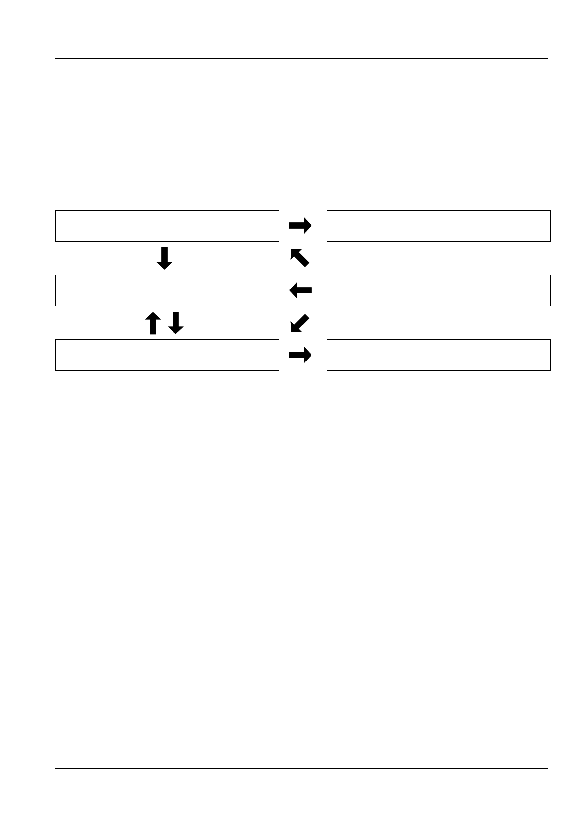
References between different information types
The maintenance manual and workshop manual are mainly divided
into function groups, see
Workshop manual con tent s page 5
parts are broken out as separate parts to increase usability, e.g.,
"Technical data".
The basic rule of searching for inf ormation is to use function groups to
find different types of informatio n regarding th e function or c omponent
in question. As a complement to this, there are references according
to the below.
Hydraulic diagrams
(Section E)
Error codes
(Section D)
Wiring diagrams
(Section E)
. Certain
• From Function description to Component description, to enable
fast finding of more information about the different components
that create a function.
• From Function description to Hydraulic diagram, to enable fast
finding of the right hydraulic diagram for the function in question.
• From Component description or Function description to Diagnostics, to enable fast find ing of the right di agnostic me nu that can be
used to check the component (only applies to electrical
components).
• From Diagnostics to Wiring diagrams. to en able fast findi ng of the
right circuit diagram for further troubleshooting.
• From Diagnostics to Component description or Function description. To enable fast finding of more information about the component's appearance and position when troubleshooting.
• From Error codes to Diagnostics , to enable fast finding of the right
diagnostic menu to troubleshoot component or function in
question.
• From Error codes to Function description or Component description, to enable fast fi nding of mo re informat ion about c omponent s
or function.
Workshop manual DRF 400-450
VDRF03.02GB
Page 12

8 A Foreword – Reading instructions
page –
Symbol for optional equipment
Product alternatives and optional equipment
The information in the manual is divided into modules. If a product alternative or optional equ ipm en t is fitte d, ha ndl ing may di ffer fro m th at
indicated in the modules depending on what is being described. See
below.
Special equipment is not described in the manual. If uncertain as to
what equipment is fitted to the machine, use the machine card to de
termine which information is relevant. See
Product alternative
Product alternative describes options that are fitted instead of a specific piece of standard equipment (e.g. engine alternative).
Equivalent informat ion fo r diffe rent p roduct altern ative s are describ ed
consecutively in separate segments within the same function group.
To indicate that there are diff erent alternatives, "Product alternat ive" is
added to the heading tog ether with a simple descripti on of the alterna
tive, e.g. "(Product alternative Climate control system ECC)". In addition, the alternative that is an option is marked with the symbol for
optional equipment.
Optional equipment
Optional equipment refers to options that can be added to standard
000264
equipment for more or improved functions.
Information on auxil iary equipmen t is described in se parate segment s
together with the standard equipment. The optional equipment de
scription covers how the eq uipment affects standard func tion and what
components are added.
Machine card page 8
-
.
-
-
page –
Machine card
NOTE
If the machine has been modified after delivery, information on
the machine card may be incomplete or incorrect.
The machine card indic ate s of wh ic h draw i ngs the mac hi ne co ns is ts,
in many cases these can be associated options and product alterna
tives. For more inform ation about hand ling of product alternatives an d
optional equipment, see
page 8
. The machine card is delivered with the parts catalogue.
Product alternatives and op tion al equ ipm en t
The machine card is divided into the same function groups as the
spare parts catalogue, maintenance manual and workshop manual.
For reasons of practicality, the machine card only uses the first and
second level of the function group register. The function groups are
written in groups of four char acters, e.g. group 0107 refers to group 1.7
Cooling system in the manual.
For more information on how the mach ine card is used to order spare
parts, see the foreword of the spare parts catalogue.
If the information on the card machine does not help, contact
Cargotec.
-
VDRF03.02GB
Workshop manual DRF 400-450
Page 13
A Foreword – Reading instructions 9
NOTE
All documents that accompany the machine are non-registered
documents. No notification is made regarding changes.
page –
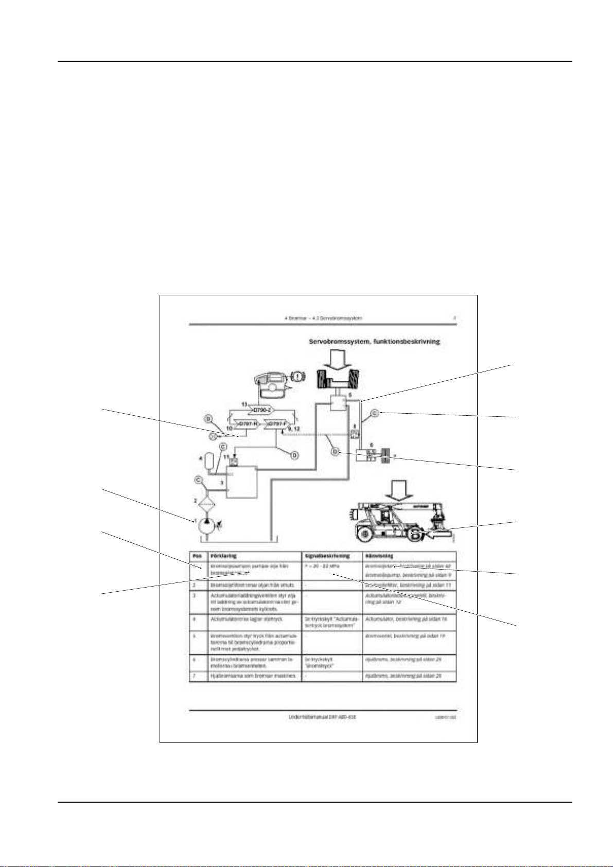
Function descriptions
Function descriptions are schematic overviews that describe how a
function works as well as which components and signals work
together.
Function descriptions describe the function i n a logic al flow from i nput
signal to desired output signal. Most functions require that preset con
ditions are fulfilled for the fu nctio n to be ac tivat ed. In th ese ca se s, the
conditions are listed above the illustration.
Function descriptions use symbols to illustrate components such as
valves, sensors, etc.
-
1
10
2
3
9
8
4
5
7
6
000520
Workshop manual DRF 400-450
VDRF03.02GB
Page 14

10 A Foreword – Reading instructions
Example of function description
1. Hydraulic force (solid double line)
2. Flag pressure check connection (Check point), indicates that
there is pressure check connection for checking pressure signal
3. Flag diagnostic test, indicates that the signal can be checked with
diagnostic test, see section
Diagnostics
4. Illustration of function, (apply brake)
5. Reference to description of component
6. Signal description, refer ence va lue for sig nal out from componen t
7. Description of component's function
8. Position number, reference to position in illustration
9. Position number in illustration, reference to row in table
10. Electric power (solid single line)
8 Control system,
group
8.4
VDRF03.02GB
Workshop manual DRF 400-450
Page 15
A Foreword – Reading instructions 11
12
34
56
78
M
910
11 12
D790-1
13 14
D797-F
15 16
17 18
˚C
19 20
˚C
21 22
Pa
23
˚C
Pa
24
25
26 27
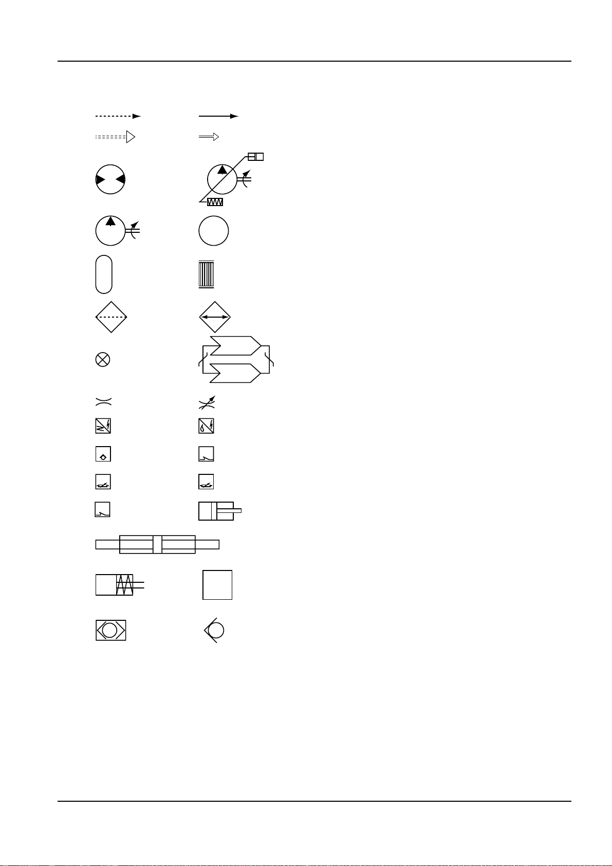
Symbol explanation function descriptions
The following symbols are used in function descriptions, the symbols
are based on stan dard symbols used in wiring and hy draulic diagrams .
1. Electric control signal
2. Electric force
3. Hydraulic control signal
4. Hydraulic force
5. Hydraulic motor
6. Hydraulic oil pump with variable displacement
7. Hydraulic oil pump with fixed displacement
8. Electric motor
9. Accumulator
10. Disc brake
11. Filter
12. Radiator
13. Bulb
14. Control system, two control units with CAN-bus
15. Restriction
16. Adjustable restriction
17. Inductive position sensor
18. Electrically controlled servo valve
19. Thermal bypass valve
20. Temperature-controlled sw i tch
21. Temperature sensor
22. Pressure sensor
23. Pressure-controlled switch
24. Hydraulic cylinder
25. Double-acting hydraulic cylinder
26. Spring brake cylinder
27. Valve block
28. Shuttle valve
29. Non-return valve
28 29
000523
Workshop manual DRF 400-450
VDRF03.02GB
Page 16

12 A Foreword – About the documentation
About the documentation
page –
Documentation sections
The documentation to the machine comprises the following sections:
Operator’s manual
The operator’s manual is supplied with the machine in the cab.
Documentation kit
Maintenance manu al and spare p arts catalogue wi th machine card are
supplied with the machine as a separate documentation kit.
Supplementary documentation
Supplementary documentation can be ordered for the machine.
• Workshop manual.
• Supplier documentation for engine, transmission and drive axle.
page –
Ordering of documentation
Documentation is ordered from your Cargotec dealer.
Always specify the publication number when ordering.
See the machine card for publication number.
VDRF03.02GB
Workshop manual DRF 400-450
Page 17

A Foreword – Feedback 13
Feedback
page –
To: Cargotec Sweden AB
Technical Documentation
Torggatan 3
SE-340 10 Lidhult
SWEDEN
Fax: +46 372 263 93
From:
Company / Sender: ..........................................................................................................................................
Telephone:
..........................................................................................................................................................
Form for copying
Cargotec’s ambition is that you who work with maintenance of a Kalmar machine shall have access to correct information.
Your feedback is important to be able to improve the information.
Copy this form, write dow n your views and s end it to us. Tha nk you for
your participation!
Manual
information
Suggestions,
views,
remarks,
etc.
E-mail:
.................................................................................................................................................................
Date: .................................... - .................. - ..................
Name / Publication number: .............................................................................................................................
Section / page n umber: ....... ................. ................. ................ ............ ................ ................. ................................
...........................................................................................................................................................................
...........................................................................................................................................................................
...........................................................................................................................................................................
...........................................................................................................................................................................
...........................................................................................................................................................................
...........................................................................................................................................................................
Workshop manual DRF 400-450
VDRF03.02GB
Page 18

14 A Foreword – Feedback
VDRF03.02GB
Workshop manual DRF 400-450
Page 19

B Safety 1
B Safety
Table of Contents B Safety
mm mm mm mm mm mm
Safety .............................................................................................................. 3
General safety information ......................................................................... 3
Safety concerns everyone! ................................................................................ 3
A near accident is a warning! ............................................................................ 3
Safety instructions ...................................................................................... 4
General ............................................................................................................. 4
Service position ................................................................................................. 4
Hydraulic and brake systems, depressurising ................................................... 5
Oils .................................................................................................................... 6
Fuel system ....................................................................................................... 7
Clothing, etc. ..................................................................................................... 8
Several mechanics on the same machine ......................................................... 9
Working under machine .................................................................................... 9
Lifting heavy components ............................................................................... 10
Vibrations ........................................................................................................ 10
Noise ............................................................................................................... 11
Solvents .......................................................................................................... 11
Fire and explosion risks ................................................................................... 12
Fluid or gas under pressure ............................................................................ 13
Coolant ..................... .......................................................... ............................. 14
Refrigerant ...................................................................................................... 14
Air pollution ..................................................................................................... 15
Tensioned springs ........................................................................................... 16
Electric motors ................................................................................................. 16
Rotating components and tools ....................................................................... 17
Tyres and rims ............................. ....... ...... ...... ....... ...... ....... ...... ....... ...... ....... ... 18
Lifting equipment ......................... ....... ...... ...... ....... ...... ....... ...... ....... ...... ....... ... 18
Spare parts .. ...... ....... ...... ....... ...... .................................................................... 19
Non-ionised radiation ......................... ...... ...... ................................................. 20
Environment ............................................................................................. 21
General ........................................................................................................... 21
Workshop manual DRF 400-450
VDRF03.02GB
Page 20

2B Safety
VDRF03.02GB
Workshop manual DRF 400-450
Page 21

mm mm mm mm mm mm
B Safety – Safety 3
Safety
General safety information
page –
page –
Safety concerns everyone!
The safety information concerns everyone who works with the machine! Persons who do not follow the safety instructions given in this
manual must make abs olutely s ure that the work is perf ormed wi thout
risks of personal injury and without risk of damage to machine or ma
chine property!
Remember to:
• follow the instructions in this ma nual
• be trained for the work in question
• follow local laws, safety rules and regulations
• use the correct equipment and tools for the job
• wear the correct clothes
• use common sense and work carefully. Do not take any risks!
Cargotec has in this publication docum ented and warned f or situations
and risks that may occu r in connection w ith using as we ll as service or
repairs of the machine during normal circumstances.
That is why it is importa nt that all who work with the machi ne, or repair
or service the machine, read and follow the information in the Workshop Manual and Operator’s Manual.
A near accident is a warning!
A near-accident is an unexpected event where neither persons, machine or property are injured or damaged. However, a near-accident
indicates that there is an injury ri sk and acti ons must be ta ken to avoi d
the risk of injuries.
-
Workshop manual DRF 400-450
VDRF03.02GB
Page 22

4 B Safety – Safety instructions
Safety instructions
page –
General
Read, consider a nd follow the safety instructi ons below before starting
to work in the machine:
•
Service position page 4
•
Hydraulic and brake systems, depressurising page 5
•
Oils page 6
•
Fuel system page 7
•
Clothing, etc. page 8
•
Several mechanics on the same machine page 9
•
Working under machine page 9
•
Lifting heavy components page 10
•
Vibrations page 10
•
Noise page 11
•
Solvents page 11
•
Fire and explosion risks page 12
•
Fluid or gas under pressure page 13
•
Coolant page 14
•
Refrigerant page 14
•
Air pollution page 15
•
Tensioned springs page 16
•
Electric motors page 16
•
Rotating components and tools page 17
•
Tyres and rims page 18
•
Lifting equipment page 18
•
Spare parts page 19
•
Non-ionised radiation page 20
page –
Machine with a fully retracted and lowered boom
VDRF03.02GB
Service position
General
Service position is us ed for servic e, mainten ance and ot her situations
when the machine needs to be secured.
Service position means:
• Machine parked, that is, parking brake applied.
• Boom fully retracted and lowered to horizontal position.
• Engine off.
• Main electric power off (with battery disconnec tor).
003603
Workshop manual DRF 400-450
Page 23
B Safety – Safety instructions 5
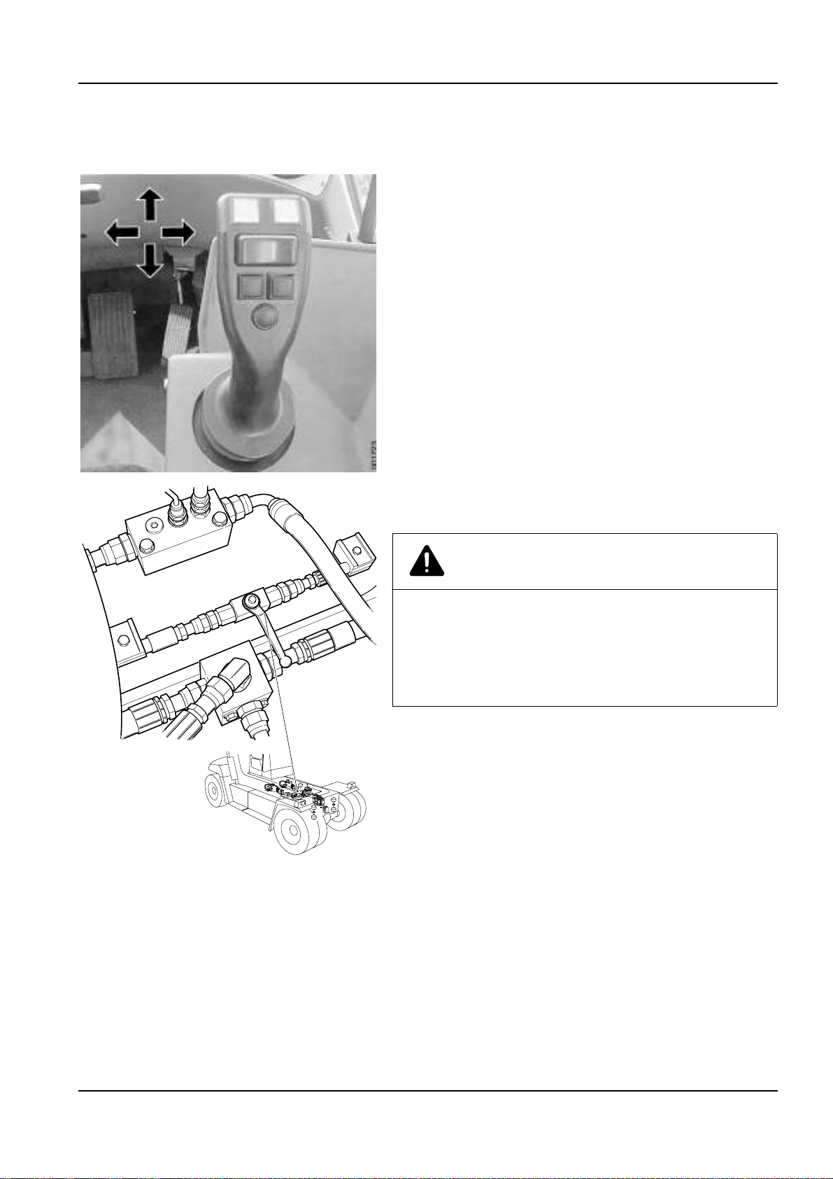
page –
Hydraulic and brake systems, depressurising
1 Machine in service position.
2 Depressurise the hydraulic system.
Turn the start key to position I and activate extension out, a
strong hissing sound is heard if there is pressure in the hy draulic
system. Activate lift, extension and side shift several times.
3 Turn the start key to position 0 and turn off the main electric
power.
4 Depressurise the attachment.
Open the relief valve for top lift.
The illustration above shows closed valve.
CAUTION
Hydraulic oil may be directed the wrong way.
Risk of damage to the fine filter for hydraulic oil.
Check that the relief valve top lift is closed before the
engine is started after the completion of work.
002269
Workshop manual DRF 400-450
VDRF03.02GB
Page 24
6 B Safety – Safety instructions
5 Depressurise the brake system by o pening the drain va lve on the
accumulator charging valve.
NOTE
Keep the drain valve open as long as work is in progress.
NOTE
After work is finished, c lose drain valv e and t ighten the loc k
ring.
page –
Oils
The following safety instructions shall be followed for work when handling oils.
WARNING
Warm and pressurised oil.
Always depressurise hydraulic and brake systems
completely before starting to work in the systems.
Hydraulic and brake systems are pressurised and the
oil may cause personal injuries.
Avoid skin contact with the oil, use protective gloves.
Warm oil can cause burn injuries, rashes and
irritation! The oil may also be corrosive to mucous
membranes in, e.g., the eyes, skin and throat.
IMPORTANT
VDRF03.02GB
Always clean the area around components and
connections before they are loosened. Dirt in oil
systems causes increased wear, resulting in
subsequent material damages.
Always take action to avoid spills. In places where
drain containers cannot be used, u se a pump or ho se
for safe handling.
Always check that plugs seal tight before collection
containers are moved.
Handle all oil as environmentally hazardous waste.
Oils freely released cause damage to the environment
and may also cause fires. Waste oils/fluids shall
always be handled by an authorised company.
Workshop manual DRF 400-450
Page 25
B Safety – Safety instructions 7
page –
Fuel system
The following safety instructions shall be followed for work when handling fuel.
DANGER
Pay attention to the risk of fire when working on the
fuel system.
Work on the fuel system shall be avoided when the
engine is warm since fuel can spill on hot surfaces
and may ignite.
Ensure that naked flames, sparks or glowing objects
have been removed before work begins on or near the
fuel system.
Do not smoke in the vicinity of the machine when
working on the fuel system.
WARNING
Use protective gloves and protective goggles. If a
component is to be disconnected, hold a rag over the
connection as protection and to collect fuel. The
engine’s fuel system operates at very high pressure.
The pressure is so high that the jet can injure the skin,
resulting in severe injuries. Risk of personal injuries.
Avoid skin contact with fuel, use protective gloves.
Fuel is corrosive to mucous membranes in, e.g., eyes,
skin and throat.
CAUTION
Always clean the area around components and
connections before they are loosened. Dirt in the fuel
may cause malfunctions and engine stop in
undesirable situations as well as increase wear,
resulting in subsequent material damages.
Workshop manual DRF 400-450
VDRF03.02GB
Page 26

8 B Safety – Safety instructions
IMPORTANT
Always take action to avoid spills. In places where
drain containers cannot be used, u se a pump or ho se
for safe handling.
Always check that plugs and connections seal tight
before moving collection containers.
Handle the fuel as environmentally hazardous waste.
Fuel freely released causes damage to the environ
ment and may also cause fires. Fuel shall always be
handled by an authorised company.
-
page –
Clothing, etc.
Clothes should be in good condition. Rem ove loosely hangi ng clothing
(tie, scarf, etc.). Do not wear clothes with wide sleeves, wide trouser
legs, etc.
Remove jeweller y as it m ay con duct e lectric ity an d get ca ugh t in moving parts.
Long hair should be adequately gathered since it can easily ge t caught
in moving parts. Be careful when working with welding or an open
flame since hair easily catches on fire.
VDRF03.02GB
Workshop manual DRF 400-450
Page 27

B Safety – Safety instructions 9
001977
page –
Several mech anics on the same machine
WARNING
If several mechanics are working on the same vehicle,
take extra care so that unintentional movements do
not injury another person. Communicate so that eve
ryone knows where all are and what they are doing.
Risks
Work with wheels or axle suspension, mountings, etc. may result in
components on the other side moving and causing damage/injury.
Movements performed from the operator’s s tati on, e.g., movement o f
lifting equipment, may cause severe personal injuries.
Safety precautions
• Make sure that the machine's lifting equipment is completely lowered or secured in another way.
• Move battery disconnector to position zero, remove the key.
• Be aware of the risks when several persons work around the
vehicle.
• Make your co-workers aware of what you’re working wi th.
• Do not work with drive wheels on the ma ch ine's both sides at the
same time.
-
page –
A
Locks on lift mast for securing the liftable cab in the
raised position.
Working under machine
Working under cab
On machines with liftable cab, the cab must be secured in the raised
position with the locks designed for this purpose.
Working under the frame
A raised vehicle may not, for an y reason, be supported or li fted in parts
that belong to the wheel sus pension or steering. Alway s support under
the frame or wheel axle.
Risks
Mechanical or hydraulic tools and lifting devices can fall over or accidentally be lowered due to malfunctions or incorrect use.
Safety precautions
Use axle stands and supports that stand securely.
Lifting tools should be inspected and type approved for use.
Workshop manual DRF 400-450
VDRF03.02GB
Page 28

10 B Safety – Safety instructions
page –
Lifting heavy components
WARNING
Careless handling of heavy components can lead to
serious personal injury and material damage.
Use type approved lifting tools or other devices to
move heavy components. Make sure tha t the device is
stable and intact.
Risks
Unsuitable lift slings, straps, etc. may break or slip.
The centre of gravity (balance point) of the component can change
during the course of the work, and the co mpone nt may t hen make unexpected movements which may cause severe personal injuries and
material damage.
A component lifted w ith lifti ng equipmen t can start to turn if the equi librium is upset.
A component lifted using an overhead crane may start to swing back
and forth, which can cause severe crushing injuries or material
damage.
Safety precautions
Lifting with lifting device. Use lifting tools or other tools, especially
when there are such adapted for certain work. See worksh op manu al
for methods.
If lifting must be performed without lifting device:
• Lift near the body.
• Keep your back vertical. Raise and lower with legs and arms, do
not bend your back. Do not rotate your body while lifting. Ask for
assistance in advance.
• Wear gloves. They're good protection against minor crushing injuries and cuts to fingers.
• Always use protective shoes.
page –
Vibrations
In case of long-term use of vibra ting tools, for exampl e, impact nut runners or grinders, injurie s may be sust ained a s vibr ations can be t ransmitted from tools to hands. Especially when fingers are cold.
Safety precautions
Use heavy gloves to protect against cold and somewhat against
vibrations.
Switch between work duties to give the body time to rest.
Vary work position a nd grip so that the body is not stres sed in only one
position by the vibrations.
VDRF03.02GB
Workshop manual DRF 400-450
Page 29

B Safety – Safety instructions 11
page –
Noise
Noise louder than 85 dB (A) that lasts for longer than 8 hours is considered harmful to hearing. (Limit values may vary between different
countries.) High tones (hig h frequencies) are more damaging th an low
tones at the same sound level. Impact noise can also be hazardous,
e.g. hammer blows.
Risks
At noise levels higher than the limits hearing damage can occur. In
more severe cases, hearing damage can become permanent.
Safety precautions
Use hearing protecti on. Make sure that it is tested and p rotects against
the noise level in question.
Limit noise with noise-absorbing dividers, for example, noise-absorbing materials in roof and on walls.
page –
Solvents
Fluids that (as opp osed to w ater) dissolve grease, paint, lacque r, wax,
oil, adhesive, rubber, etc. are called organic solvents. Examples:
White (petroleum) spirits, gasoline, thinner, alcohols, diesel, xylene,
trichloroethylene, toluene. Many solvents are flammable and consti
tute a fire hazard.
-
Risks
Products containing solvents produce vapours that can cause dizziness, headaches and nausea. They may also irritate mucous membranes in the throat and respiratory tracts.
If the solvent en ds up directl y on the skin it may dry o ut and crack . Risk
of skin allergies incre ases. Solv ents ma y also cause in jury if the y penetrate through the skin and are absorbed by the blood.
If the body is continuously exposed to solvents, the nervous system
may be damaged. Symptoms include sleep disorders, depressions,
nervousness, poor memory or gene ral tire dness and fat igue. C ontin u
ous inhalation of gasoline and diesel fumes is suspected to cause
cancer.
Safety precautions
Avoid inhaling sol vent fumes by providing go od ventil ation, or wearin g
a fresh-air mask or respiratory de vice with a sui table filter for the toxic
gases.
Never leave a solvent container without tight-sealing lid.
Use solvents with a low content o f aromatic substan ces. It reduces th e
risk of injury.
Avoid skin contact.
Use protective gloves.
Make sure that work clothes are solvent-resistant.
-
Workshop manual DRF 400-450
VDRF03.02GB
Page 30

12 B Safety – Safety instructions
page –
Fire and explosion risks
Examples of flammable and explosive substances are oils, gasoline,
diesel fuel oil, organic solvents (lacquer, plastics, cleaning agents),
rustproofing agents, welding gas, gas for heating (acetylene), high
concentration of dust particles consisting of combustible materials.
Rubber tyres are flammable and cause explosive fires.
Risks
Examples of cause of ignition is welding, cutting, smoking, sparks
when working with grinders, contact between hot machine parts and
flammable materials, heat development in rag drenched with oil or
paint (linseed oil) and oxygen. Oxygen cylinders , lines and val ves shall
be kept free from oil and grease.
Fumes from, e.g., gasoline are heavier than air and may "run" down
into a sloping plane, or down in a grease pit, where welding flames,
grinding sparks or cigarette embers may cause an explosion. Evapo
-
rated gasoline explodes very forcefully.
Special cases
Diesel fuel oil with added gasoline has a lower ignition point. Risk of
explosion already at room temper ature. The expl osion risk for warm ed
diesel fuel oil is higher than for gasoline.
When changing oil in the engine, hydraulic system and transmission,
keep in mind that the oil may be hot and can cause burn injuries.
Welding on or near machine . If diesel and or other oil s have leake d out
and been absorbed b y rags , absorb ent age nts, p aper o r other porous
material, hot welding sparks can cause ignition and explosive fires.
When a battery is charged, the battery fl uid is d ivided i nto oxyg en and
hydrogen gas. This mix ture is ve ry ex pl os iv e. The risk of explosion is
especially high when using a boo ster b atte ry or q uick-c harger , as th is
increases the risk of sparks.
Today’s machines contain a lot of electronic equipment. When welding, the control units must be disconnected and the electric power
must be turned off with the batte ry disconnector. Powe rful welding currents may otherwise short-circuit the electronics, destroy expensive
equipment or cause an explosion or fire.
Never weld on pai nted s urfaces (re mo ve pai nt, by bla sting a t leas t 10
cm around the weldi ng or c utting poi nt). Us e gloves , br eathin g protec
tion and protect ive g lass es. Als o, w eldin g work may not b e done near
plastic or rubber mat eria ls with out firs t pro tec tin g t hem fro m th e h eat .
Paints, plastics, a nd rubber deve lop a numbe r of substanc es that may
be hazardous to health when heated. Be careful with machines that
have been exposed to intense heat or fire.
-
VDRF03.02GB
Workshop manual DRF 400-450
Page 31

B Safety – Safety instructions 13
Safety precautions
Store hazardous substance in approved and sealed container.
Make sure that there is no ignition source near flammable or explosive
substances.
Make sure that ven tilation is adequ ate or there is an ai r extraction unit
when handling flammable substances.
page –
Fluid or gas under pressure
High-pressure lines can b e damaged during w ork, and fluid or gas c an
stream out.
There may be high pressure in a line even if the pump has stopped.
Therefore, gas or fluid can leak out when the connection to the hose
is loosened.
A gas cylinder subjected to careless handling can explode, for example, if it falls onto a hard surface. Gas can stream out through damaged valves.
Risks
Risk of damage/injuries in connection with work on:
• Hydraulic systems (e.g., working hydraulics and brake system).
• Fuel system.
• Tyre repairs.
• Air conditioning.
Safety precautions
• Use safety glasses and protective gloves.
• Never work on a pressurised system.
• Never adjust a pressure limiting valve to a higher pressure than
recommended by the manufacturer.
• A hydraulic hose that swells, for example, at a connection, is
about to rupture. Replace it as soon as possible! Check connections thoroughly.
• Use fluid when checking for leaks.
• Never blow clothes clean with compressed air.
• Discarded pressure a ccum ula tor s ha ll first be depressurised an d
then punctured before it is discarded (to avoid risk of explosion).
Carefully, drill a hole with 3 mm diameter after depressurising.
• Never use your hands directly to detect a leak. A fine high-pressure stream from a hydraulic hose can easily penetrate a hand
and causes very severe injuries.
Workshop manual DRF 400-450
VDRF03.02GB
Page 32

14 B Safety – Safety instructions
page –
Coolant
The coolant in the machine’s cooling system consists of water, anticorrosion compound and (when needed) anti-freeze fluid, for example,
ethylene glycol.
Coolant must not be drained into the sewer system or directly onto the
ground.
Risks
The cooling system operates at high pressure when the engine is
warm. Hot coolant c an j et ou t an d ca us e sc al din g in case of a leak or
when the expansion tank cap (filler cap) is opened.
Ingesting ethylene glyco l and anti - co rros io n com pou nd is danger ous
and hazardous to health.
Safety precautions
• Use protective gloves and safety glasses if there is a risk of
splashing or spraying.
• Open the filler cap first, to release the excess pressure. Open
carefully. Hot steam and coolant can stream out.
• If possible, avoid working on the cooling system when the coolant
is hot.
page –
Refrigerant
Refrigerant is used in the machine’s air conditioning system.
Work on the air cond itioning system must be performed by accredi ted/
authorised and traine d personnel a ccording to national leg islation and
local regulations.
Risks
The air conditioning operates at high pressure. Escaping refrigerant
can cause fr ostbite.
Refrigerant that is heated (e.g., when repairing leaking climate/AC
system), generates gases that are very dangerous to inhale.
Safety precautions
• Use special instructions and equipment for refrigerant according
to the manual when working on the air conditioning system. Spe
cial certification and authorisation is often required of the person
who may do the work. (Note national legislation and local
regulations!)
• Use protective glov es and s afety glasses if there’s a ri sk of leaks.
• Make sure that heat-p roducing sources o r objects are not cl ose by
(cigarette glow, welding flame).
-
VDRF03.02GB
Workshop manual DRF 400-450
Page 33

B Safety – Safety instructions 15
page –
Air pollution
Air pollution is the impurities in t he air arou nd us and whic h are regarded as hazardous to health. Certain pollution is more prominent in certain environments.
The following hea lth-hazard ous air pollutio n is e special ly promi nent in
workshops:
• Carbon monoxide (fumes) is present in exhaust fumes. Odourless and therefore especially dangerous.
• Nitrogen oxides (nitrous gases) are present in exhaust fumes.
• Welding smoke espec ially h azardous to health when wel ding on
oily surfaces, galvanised or lacquered materials.
• Oil mist for example, when applying anti-corrosion agent.
• Grinding dust and gases ge nera ted wh en g rin ding and heating
plastics, lacquer, anti-corrosion agents, lubricants, paint, etc.
• Isocyanates are present in certain paints, fillers, adhesives and
foam plastics used on machines.
Risks
Sulphuric acid mist is corrosive and injures the respiratory tracts.
(Generated when heating certain plastics and paints.)
Isocyanates can be released in the form of steam, dust (or may be
present in aerosols) when cut ting, grinding or w elding. Can irrit ate mu
cous membranes producing symptoms similar to asthma and impairing lung function . Even bri ef exposure to high concen trations can give
problems with persistent high sensitivity.
-
Safety precautions
• Make sure of adequate ventilation with fresh air when welding,
battery charging and other work when hazardous gases are
generated.
• Use suitable protective gloves and breathing protection when
there is a risk of oil m ist. Make sure tha t the protec tion is oil-pro of.
• Apply oil-resistant protective lotion to unprotected skin.
• Make sure that an eye-wash station is in the immediate vicinity
when working with corrosive substances.
• Avoid unnecessary operation of the machin e inside the works hop.
Connect an air extractor to the exhaust pipe so that the exhaust
fumes are removed from the workshop.
Workshop manual DRF 400-450
VDRF03.02GB
Page 34

16 B Safety – Safety instructions
page –
Tensioned springs
Examples of tensioned springs:
1. Torque springs in pedals for example
2. Return spring (cup springs) in parking brake cylinder.
3. Lock rings
4. Gas springs
Risks
If a tensioned spring releases, it is sho t out by the spring force and can
also take adjoining parts with it.
Small springs can cause eye injuries.
Parking brake springs are tensioned with high force and can cause
very severe accidents if they are accidentally released in an uncon
-
trolled manner.
Gas springs and gas-charged shock absorbers are tensioned with
high force and c an cause very seve re accidents if th ey are accidentally
released in an uncontrolled manner.
Safety precautions
• Use safety glasses.
• Lock rings should be of a suitable type and in good condition.
• Follow the instruct i ons in th is and other manual when perf orm ing
maintenance and changing parts and components.
• Always use recommended tools.
page –
Electric motors
Safety precautions
Always turn off the battery disconnector when working on electric
motors.
Always block the machine’s wheels and make sure that the parking
brake is activated and that the gear selector is in neutral position before starting any work on the machine.
VDRF03.02GB
Workshop manual DRF 400-450
Page 35

B Safety – Safety instructions 17
page –
Rotating components and tools
Examples of rotating components and tools:
• Cooling fan
•Drive belts
• Propeller shafts
•Drills
• Grinders
Risks
Rotating components, for example, fans or shafts, can cause severe
injuries if touched.
Drills, lathes, grind ers or other ma chines with ro tating par ts can cause
severe accidents if clot hes or hair get caught and are wound up in the
machine.
Safety precautions
• Do not use gloves when workin g with a drill.
• Remove loose, hanging clothing, scarf or tie.
• Never use clothing with wide sleeves or trouser legs.
• Make sure that clothing is intact and in good condition.
• Long hair should be gathered up in a hair-net or similar.
• Remove large or loose hanging jewellery from hands, arms and
neck.
Workshop manual DRF 400-450
VDRF03.02GB
Page 36

18 B Safety – Safety instructions
page –
Tyres and rims
DANGER
Tires shall be regarded as pressure reservoirs. If handled incorrectly, they constitute a fatal danger
Parts can be thrown with explosive force and may
cause severe injuries.
Never repair damaged tyres, rims or lock rings. Tyre
changes shall be performed by authorised personnel.
Risks
Dismantling wheels: Tyres, rims or lock rings can be thrown.
Inflating of wheels: Tires, rims or lock rings may be ejected.
Safety precautions
• Always deflate the tyre before starting to work on the wheel.
• Check that tyres, rims and lock rings aren’t damaged. Never repair damaged rims or lock rings.
• Wheels shall be infla ted on the machi ne or in a pro tective devic e,
designed and dimensioned so that it can handle or dissipate a
shock wave from a tyre explosion as well as catch the ejected
parts.
• Use protective screen and safety glasses.
page –
Lifting equipment
When working on the machine in general, and with the machine’s lifting equipment in particular, the greatest caution must be exercised
with respect to securing the boom and attachment.
For this reason, always be in the ha bit of having the boom fully lowered
and fully retracted during work on the machine.
Risks
Risk of crushing if the machine’ s lif ting equipment is not lowered or
secured.
Risk of crushing is extra high when depressurising the hydraulic system, see
Hydraulic and brake systems, depressurising page 5
.
Safety precautions
• Do not start work until the boom is lowered and fully retracted if
possible.
VDRF03.02GB
Workshop manual DRF 400-450
Page 37

B Safety – Safety instructions 19
page –
Spare parts
WARNING
The following parts must, for safety reasons, only be
replaced with original spare parts:
• Brake valve
• Drive axle
• Valve for mini-wheel/lever steering
• Steering valve (Orbitrol)
• Steering valve incl. priority valve
• Steering axle
• Steering cylinder
•Rims
• Lift boom
• Boom nose extension
• Lift cylinder
• Valve block lift
• Extension cylinder
• Valve block extension
• Rotation motor unit
• Tilt cylinder
• Twistlocks, lifting shoe
• Safety switch (for hydraulic function)
• Emergency switch
•Frame
• Accumulator
• Main valve load handling
• Accumulator charging valve
• All control units
Workshop manual DRF 400-450
VDRF03.02GB
Page 38

20 B Safety – Safety instructions
page –
Non-ionised radiation
WARNING
Extra equipment such as communication radio, RMI,
phone, etc. can emit non-ionised radiation.
Danger of disruption to active or inactive medical
products.
Use communication radio, RMI, phone, etc. when
there are no people with active or inactive medical
products in the vicinity.
NOTE
When there are no people wit h act iv e or ina cti ve pr odu ct s in th e
vicinity the phone and communication radio in the cab may be
used.
Equipment should not be used durin g ope ration or l oad h andlin g
as your concentration as operator is reduced.
Cargotec accepts no re sponsibili ty for equipment n ot installed by
Cargotec or with Cargotec approved installation.
VDRF03.02GB
Workshop manual DRF 400-450
Page 39

B Safety – Environment 21
Environment
page –
General
Ever-increasing indust rialisation o f our world is ha ving a sign ificant impact on our global environ ment. Nature , animals and man are sub jected daily to risks in conn ection with various forms of chemical h andling.
There are still no environmentally safe chemicals, such as oils and
coolants, available on the market. Therefore, al l w h o h and le , pe rform
service on or repair machines must use the tools, assisting devices
and methods necess ary to pro tect the enviro nment in an environ men
tally sound manner.
By following the simple rules below, you will contribute to protecting
our environment.
-
Recycling
Well-thought out re cycling o f the mach ine is the cornerstone of ending
its life cycle and being able to re-use materials in new products. Ac
cording to calculations by Cargotec, the machine can be recycled to
more than 90% by weight.
-
Environmentally hazardous waste
Components such as batteries , plastics , and other materi als that may
be considered as enviro nm enta ll y ha za rdous waste must be handl ed
in an environmentally correct manner.
Discarded batteries c ontain subs tances h azardous to p ersonal he alth
and the environment. Th erefore, handle batteries in an e nvironmental
ly safe manner and according to national regulations.
-
Oils and fluids
Oils freely discharged cause environmental damage and can also be
a fire hazard. Therefor e, when e mptying and draini ng oils or fuel, take
appropriate action to prevent unnecessary spills.
Waste oils and fluids must always be taken care of by an authorised
disposal company.
Pay close attention to oil leaks and other fluid leaks! Take immediate
action to seal the leaks.
Air conditioning unit
The refrigerant in the air conditioning unit for the cab contributes to the
greenhouse effect and may not be i ntentionally released in to the open
air. Special training is required for al l servic e work on the air condi tion
ing unit. Many coun tries d emand certi fication by a gov erning au thority
for such work.
Working in a contaminated area
The machine shall be equipped for work within a contaminated area
(environmental contam ina t io n o r hea lth - haz ard ous ar ea) b efo re w ork
is started. Also, special loc al regulations appl y to such handling and to
service work on such a machine.
-
Workshop manual DRF 400-450
VDRF03.02GB
Page 40

22 B Safety – Environment
Declarations
The machine does not contain asbestos.
The machines contains lead in batteries and in electric cabling. In cer-
tain models, there are lead castings as counterweight.
If the machine is equ ipped with air con ditioning , then re frigerant o f the
type R134a is used, in an amount between 1-3 kg.
VDRF03.02GB
Workshop manual DRF 400-450
Page 41

mm mm mm mm mm mm
C Preventive maintenance – C Preventive maintenance 1
C Preventive maintenance
C Preventive maintenance
page –
The information is found in the Maintenance Manual
The information is found in the Maintenance Manual.
For information on how to order the Maintenance Manual, see the
section
A Foreword
.
Workshop manual DRF 400–450
VDRF03.02GB
Page 42

2 C Preventive maintenance – C Preventive maintenance
VDRF03.02GB
Workshop manual DRF 400–450
Page 43

0 Complete mach ine 1
0 Complete machine
Table of Contents 0 Complete machine
mm mm mm mm mm mm
Complete machine......................................................................................... 3
Complete machine, description ....... ....... ...... ...... ....... ...... ....... ............................... 3
Troubleshooting, general work instructions ............................................................ 4
Troubleshooting without an error code, example ................................................... 5
Troubleshooting with error code, example ............................................................. 5
Troubleshooting cable harness .............................................................................. 7
Troubleshooting hydraulic hoses ............................................................................ 8
Workshop manual DRF 400-450
VDRF03.02GB
Page 44

20 Complete machine
VDRF03.02GB
Workshop manual DRF 400-450
Page 45

mm mm mm mm mm mm
0 Complete machine – Complete machine 3
Complete machine
page –
Complete machine, description
The Kalmar DRF 400–450 is a "Re achstacker" for co ntainer handli ng.
The machine a liftin g capaci ty of 40–4 5 tonnes d epending on versio n.
The drive source is a six-c ylinder, four-strok e diesel engin e with direct
injection.
The transmission is hydromechanical, with constant mesh gears. It
has four speeds forwards and fou r speeds in reverse. Engi ne power is
transmitted by a torque converter.
The driveline/axle comprises a propeller shaft and a rigid drive axle
with hub reduction. Drive is via the front wheels.
The service brake is of wet disc type, built together with drive wheel
hubs. The parking brake is a disc brake and acts on the drive axle in
put shaft.
Steering is via the rear wheels and a dou ble acting hydrau lic cylin der.
The steering axle is pendulum-suspended in the frame.
The wheels are mounted on the hubs with clamps. Twin wheels are
mounted on the drive axle, while the steering axle has single wheels.
Load handling comprises components and functions for managing
loads. Loads are lifted with and attachment that is fitted on a liftable
telescopic boom. Load handling is divided into lifting/lowering, exten
sion, side shift, spreading, rotation, tilt, levelling and load carri er fun ctions.
• Lifting/lowering is the function used to raise and lower the boom.
• Extension is the function to extend the boom in and out.
• Side shift is used to move th e lift attachment laterally in relati on to
the machine.
• Spreading is used to adjust the width between the attachment’s
lifting points.
• Rotation is rotating the load in relation to the machine.
• Tilt is angling the load in the longitudinal direction of the truck.
• Levelling is angling the load in the lateral direction of the truck.
• The load carriers are designed to hold a fixed load.
The control system is functions for warni ng the opera tor of dange rous
situations and machine faults. The control system has diagnostic re
sources that simplify troubleshooting.
The frame supports the machine. Mounted in the frame are the engine,
transmission, drive axle and steering. The side of the frame houses
tanks for fuel, hydrauli c oil and oil for the brake system. T he cab is cen
trally located and can be tilted longitudinally. As an option the cab is
available in a side-mounted version that can be raised and lowered.
-
-
-
-
Workshop manual DRF 400-450
VDRF03.02GB
Page 46

4 0 Complete machine – Complete machine
page –
Troubleshooting, general work instructions
When troubleshooting, it is important that the work is structured and
logical. The point of the troubleshoo ting describe d in the mainten ance
manual is to exclude components as error so urce so that the real e rror
source can be pin-po inted. A suggest ed structured w ork method is de
scribed below.
When troubleshoo ting , i t is i mp orta nt t o un derstand how the mach ine
functions. Certain m alfun ctions can be pi n-p ointed directl y using f unction descriptions. Sections
0–12
contain descriptions of the various
functions of the machine.
Troubleshooting procedure
1 Check that there is battery voltage available.
• Battery disconnector, must be in position 1.
• Battery voltage, should be 22–30 V.
• Fuses, check that they are intact.
2 Check that all oil and fluid levels are normal.
•Fuel
• Engine oi l
• Transmission oil
• Brake system fluid
• Hydraulic oil
• Coolant
• Washer fluid
3 Check if there are error codes.
4 If there are error codes, use the error code lists as a guide. See
Troubleshooting with error code, example page 5
In the error code lists there are recommended actions for every
error code. Error code lists are found in section
5 If there is no error code or the problem persis ts, use the functio n
description for the function in question in section
The function description contains information on which compo-
nents are involved in the function and how these components
work together. In some cases, there is information on what con
ditions are required in order for it to be possible to activate the
function. Measureme nt points a re marked wi th flags (C fo r meas
uring outlet, D for diagnostic me nu).
.
D Error codes
0–12
.
-
.
-
-
VDRF03.02GB
Workshop manual DRF 400-450
Page 47

0 Complete machine – Complete machine 5
page –
Troubleshooting without an error code, example
1 Choose suitable section
tion that have caused the symptom.
2 Read the function description for the function in question to get
an overall understanding of which components are affected and
how these interact.
3 Use the function description and check the signals for the func-
tion in question to find where in the function chain that signal or
reaction is incorrect.
4 The fault is probably between the two units where the signal is
failing. Start by checking the component that should send the
signal.
5 If the component that is to send the signal seems to be correct,
check transmission of the signal (electric wiring or hydraulic
hoses).
For electric cabling, see
For hydraulic hoses,
see
Troubleshooting hydraulic hoses page 8
6 If the leads or hoses between the components seem in order,
then check the component that receives the signal.
0–12
to find the function and sub-func-
Troubleshooting cable harness page 7
.
.
page –
Troubleshooting with error code, example
Error codes are strong i ndica tors of mal functi ons de tected by the control system. Many error codes are connected to elec trical malfunctio ns
but there are also error codes that inte rpret associati ons between one
or several signals th at ind icate a n on- electri cal mal functi on. It’ s imp or
tant to not draw conclusions too fast based on an error code.
1 Read out error codes from the display, e.g., error code 34.
2 Use the error code lists and search information about the error
code, see "Example of error code information in error code list"
below.
Error code lists are found in section
D Error codes
.
For detailed instructi on o n re adi ng o ut e rror c od e, s ee s ec tio n
Error codes
.
3 Follow the instructions in the field “Action”.
4 Use diagnostic menus and circuit dia grams to dete rmine if the in-
put signal to the control unit is correct; see section
system
, group
8.4 Diagnostics
as well as section
8 Control
E Schematics
5 Use the function group to find more information if needed.
In section
0–12
there is functio n descriptio n, the functi on's included components and their position as well as, in certain cases,
work instructions for how components are checked, cleaned or
adjusted.
-
D
.
Workshop manual DRF 400-450
VDRF03.02GB
Page 48

6 0 Complete machine – Complete machine
6 If possible, eliminate component fault by testing the component
individually.
Electric componen ts can s ometi mes be chec ked w ith resi stanc e
measurements using a multimeter.
Hydraulic componen ts are often checked by meas uring pressure
(then described in the function group and indicated in the
section
activated mechanica ll y to d eterm in e if th e ma lfunction is electric
or hydraulic.
7 If the component’s measuremen t values are correct , conti nue by
troubleshooting electric cables and hydraulic hoses.
For electric cabling, see
For hydraulic hoses, see
8
8 If the cable is not defective, then connect the lead to the control
unit.
C Preventive maintenance
.
NOTE
The main electric power shall be turned off with the battery
disconnector!
9 Disconnect the cable from the component in question.
10 Turn on the main electric power with the battery disconnector.
11 Turn the ignition key to the operating position.
12 Check that voltage reaches the component.
). Sometimes valves can be
Troubleshooting cab le harn es s p age 7
Troubleshooting hydraulic hoses page
.
Table 1. Ex ample of error code information in error code list
Code Description Limitation Action
34 Signal error from
parking brake
switch, indicates re
leased and applied
at same time or
nothing at all.
Parking brake
cannot be
-
released.
Check cabling
between the control
unit and the
component with
diagnostic menu.
Check component.
Connections
and
components
D791-1/K8:5 S107, K8:13 S107
Diagnostic menu
HYD,
5
menu
Function
group
4.1.2 Parking
brake control
VDRF03.02GB
Workshop manual DRF 400-450
Page 49

0 Complete machine – Complete machine 7
page –
Troubleshooting cable harness
NOTE
Perform troubleshooting for all cabl es in the sam e way to avo id
damage to control units, components or measuring equipment.
1 Study the circuit diagram in questi on, check where the suspected
cable is connected and if, and if so where, it is spliced.
2 Turn off the main electric power with the battery disconnector.
3 Unplug the connector at the control unit or component in
question.
CAUTION
Wipe and re-grease the connectors.
Risk of corrosion on contact surfaces.
Clean all connectors loosened during troubleshoot-
ing using electronic cleaner 923836.0826 and regrease them with connector grease 923836.0552.
4 Check if there is open circuit.
NOTE
Some components ca nnot be checked without p ower supply
to the component. In such an event, proceed to point 5.
a. Measure resistance between connection s for the component
in the connector at the control unit or component.
b. The resistance mus t correspond with the c om pon ent . O th er-
wise there may be an open circuit or short circuit in cable harness and/or component.
5 Check if there is short circuit to frame:
a. Unplug the conne ctor at bot h the con trol unit a nd the co mpo-
nent in question.
b. Measure the resistance of one lead at a time. Measure be-
tween the lead and a frame-connected part of the machine.
c. The multimeter should show endless resistance.
Workshop manual DRF 400-450
VDRF03.02GB
Page 50

8 0 Complete machine – Complete machine
page –
Troubleshooting hydraulic hoses
WARNING
Oil under high pressure!
Personal injury!
Always depressurise hydraulic and brake systems
before starting to work on the systems.
1 Depressurise the hydraulic and brake systems; see section
.
Safety
2 Study the relevant hydraulic diagra m, check between w hichever
components the suspec t hose i s conne cted and corres pondingl y
where it is spliced.
3 Locate the hose on the machine.
Start at one component and follow the hose to the next
component.
4 Inspect the entire hose and splicin g points with res pect to chafing
damage, pinching damage and leaks.
Change damaged hoses. When removing a hydraulic hose,
change of O-ring is always recomme nded on the hos es that have
these (ORFS).
B
VDRF03.02GB
Workshop manual DRF 400-450
Page 51

1 Engine 1
1 Engine
Table of Contents1 Engine
mm mm mm mm mm mm
1 Engine ............................................................................................................. 3
1.1 Controls and instruments ............................. ............................................ 23
1.1.1 Ignition switch ...................................................................................... 23
1.1.2 Accelerator pedal ................................................................................. 24
1.2 Fuel system .............................................................................................. 25
1.2.1 Fuel tank .............................................................................................. 25
1.2.2 Sensor, fuel level ................................................................................. 25
1.6 Air intake and exhaust outlet ................ .................................................... 26
1.6.1 Air cleaning system .............................................................................. 26
1.6.3 Exhaust syst em ................................................................ ................... 26
1.6.4 Intercooler ............................................................................................ 27
1.7 Cooling system ......................................................................................... 28
1.7.4 Radiator and expansion tank ............................................................... 29
1.7.5 Cooling fan ........................................................................................... 30
1.7.7 Coolant ................................................................................................ 32
1.7.10 Engine heater ...................................................................................... 35
1.9 Engine control system .............................................................................. 36
1.9.1 Control unit , engine ................................ ....................... .. ..................... 36
1.11 Start/stop .................................................................................................. 37
1.11.1 Starter motor ........................................................................................ 37
1.11.2 Stopping device ................................................................................... 37
Workshop manual DRF 400–450
VDRF03.02GB
Page 52

2 1 Engine
VDRF03.02GB
Workshop manual DRF 400–450
Page 53

mm mm mm mm mm mm
1 Engine 3
1 Engine
page –
Engine, general
Engine alternative
The machine can be equipped with one of the following engine
alternatives:
• Volvo TWD1240VE stage II as per Directive 97/68/EC
• Volvo TAD1250VE (stage III as per Directive 97/68/EC)
• Cummins QSM11 (stage III as per Directive 97/68/EC )
If there are differences between engine alternatives, this is written in
brackets after heading s or u nder fi gures to c larify that wh ich i s sho wn.
Volvo engines have many similarities. Descriptions and instructions
that are the same for both engine alternatives are denominated "(engine alternative Volvo)". If a description or set of instructions only applies to one engine alternative then the whole engine designation is
written out, for instance "(engine alternative Volvo TAD1250VE).
Component supplier documentation
The Workshop manual only describes components and work descriptions that concern installation in the machine . For d esc rip tions and instructions for the engine’s compon ents an d syst ems, refe r to suppl ier
documentation.
References to com ponent supplier d ocumentation are only provided in
exceptional cases . If information abou t a c om po nen t i s no t f ound, the
component supplier documentation should be used.
Workshop manual DRF 400–450
VDRF03.02GB
Page 54

4 1 Engine
page –
Engine alternative Volvo, function
description
Condition Reference value Reference
Engine heater
10
D10
2, 11
Disconnected (when cable is in start lock-out is
activated)
0
I
P
II
III
D5
<˚
1, 5
D1
6, 15
D790-1 D790-2 D795
Engine heater, description page 35
˚C
bar
.
rpm
kph
18, 21
20, 22
D793
3, 7, 12
D7
D794
14, 23
D14
D797-R
17
D16
D19
19
8
M
D3
SENSORS
4
H2O
13
16
9
Pos Explanation Signal description Reference
1 The ignition key lock sends a voltage sig-
nal to the cab control unit (D790-1) when
the start key is turned to position 1 or the
preheating position.
2 Cab control unit (D 790-1) sends ign ition on
via the CAN bus. If the k ey is tu rned to the
preheating position, then preheating is
also sent on the CAN bus.
3 If preheating is activat ed with th e start key
then Control unit, engine (D794) supplies
power to the preheating element.
U = 24 V
Ignition switch, description page 23
D1: Diagnostic menu , see section
Checked by control sys tem, error shown with
system
menu 4
Section
11.5.3.1 Cab control unit
, group
and
11 Common electrics,
error code.
U = 24 V D3: Diagnostic menu , see section
system
, group
008223
8 Control
8.4.1.4 CAN/POWER,
8.4.6.4 ENGINE, menu 4
group
8 Control
8.4.6.5 ENGINE, menu 5
4 The preheating coil warms the engine
intake air.
VDRF03.02GB
- D3: Diagnostic menu , see section
Workshop manual DRF 400–450
system
, group
8 Control
8.4.6.5 ENGINE, menu 5
Page 55

1 Engine 5
Pos Explanation Signal description Reference
5 The ignition key lock sends a voltage sig-
nal to the Control unit KIT (D790-2) when
the start key is turned to the start position.
6 Control unit KIT (D790-2) transmits a start
signal on the CAN bus.
7 The engine control unit (D794) supplies
power to the starter motor.
8 The starter motor cranks the engine. -
9 The engine’s sensors send signals to the
engine control unit (D794), w hich regulates
the injectors so that the engine starts.
10 The accelerator pedal sends the cab con-
trol unit (D790-1) a voltage signal proportional to the downward press of the pedal.
U = 24 V
Checked by control
system, error shown
with error code.
U = 24 V
Checked by control system, error shown with
error code.
U = 0.5–4.5 V
Lower voltage than 0.5
V and higher voltage
than 4.5 V used to de
tect malfunction i n cable
harnesses and contro ls.
-
Ignition switch, description page 23
D5: Diagnostic menu, see section
system
Section
, group
8.4.6.4 ENGINE, menu 4
11 Common electrics,
8 Control
group
11.5.3.11 Control unit KIT
Starter motor, description (engine alternative Volvo) page 37
D7: Diagnostic menu, see section
system
, group
8.4.6.5 ENGINE, menu 5
8 Control
Starter motor, description (engine alternative Volvo) page 37
D7: Diagnostic menu, see section
system
Section
, group
8.4.6.5 ENGINE, menu 5
11 Common electrics,
8 Control
group
11.5.3.10 Engine control unit
Section
ries,
D10: Diagnostic menu, see section
trol system
menu 1
9 Frame, body, cab and accesso-
group
9.1 Controls and instruments
, group
8.4.6.1 ENGINE,
8 Con-
11 The cab control unit (D790-1) transmits a
message with the rpm re quest on the C AN
bus
12 The engine control unit (D794) increases
engine speed.
13 The NO switch for coolant level sends a
voltage signal to Control unit, engine
(D794) if the coolant level in the ex pansion
tank is low.
14 The engine control unit (D794) transmits
engine data and warning m essages on the
CAN bus.
15 The KID control unit (D795) shows e ngi ne
data via display figures.
Checked by control system, error shown with
error code.
- Section
Section
11.5.3.1 Cab control unit
11.5.3.10 Engine control unit
U = 24 V
Checked by control system, error shown with
error code.
Cooling system, description page 28
Section
11.5.3.10 Engine control unit
D14: Diagnostic menu, see section
trol system
6 and 8.4.6.7 ENGINE, menu 7
menu
- Section
11.5.3.12 KID control unit
11 Common electrics,
11 Common electrics,
11 Common electrics,
, group
8.4.6.6 ENGINE,
11 Common electrics,
group
group
group
group
8 Con-
Workshop manual DRF 400–450
VDRF03.02GB
Page 56

6 1 Engine
Pos Explanation Signal description Reference
16 The fuel level sensor (B757) sends a volt-
age signal to Control unit, frame rear
(D797-R) proportional to the fuel level in
the tank.
17 Control unit, frame rear (D797-R) transmits
fuel level on the CAN bus.
18 The KID control unit (D795) displays the
fuel level in the operating menu for engine .
19 The output shaft sensor (B758) sends the
transmission control unit (D793) pulses
with frequency proportion al to output sh aft
rpm.
20 The transmission control unit (D793)
transmits speed on the CAN bus.
21 The KID control unit (D795) shows the ma-
chine’s speed.
U = 0.5–4.5 V
Lower voltage than 0.5
V and higher voltage
than 4.5 V used to de
tect malfunction in cable
harnesses and controls.
Checked by control sys tem, error shown with
error code.
- Section
Sensor, fuel level, description page 25
D16: Diagnostic menu, see section
Control system
-
menu
Section
7
11 Common electrics,
, group
8.4.3.7 CAB,
11.5.3.3 Control unit, frame rear
11 Common electrics,
group
group
11.5.3.12 KID control unit
- D19: Diagnostic menu, see section
Control system
6
menu
Checked by control sys tem, error shown with
error code.
- Section
Section
11.5.3.9 Control unit, transmission
, group
11 Common electrics,
11 Common electrics,
8.4.7.6 TRANSM,
group
group
11.5.3.12 KID control unit
8
8
22 If output shaft rpm is so high that it reaches
the limit for the machine’s s peed limitation,
the cab control unit (D790-1) transmits a
reduce engine rpm request on the CAN
bus.
23 Control unit engine (D794) restricts engine
rpm.
Checked by control sys tem, error shown with
error code.
- Section
Section
11.5.3.1 Cab control unit
11.5.3.10 Engine control unit
11 Common electrics,
11 Common electrics,
group
group
VDRF03.02GB
Workshop manual DRF 400–450
Page 57

1 Engine 7
page –
Engine alternative Cummins QSM11,
function description
(model
Condition Reference value Reference
Engine heater
<˚
8
D8
2, 9
Disconnected (wh en cable is in start lock-out i s
activated)
0
I
P
II
III
1, 3
D1 D3
D790-1 D790-2 D795
4, 13
year-2008)
Engine heater, description page 35
˚C
bar
.
rpm
kph
16, 19
18, 20
D793
D794
12, 21
D797-R
5, 10, 15
D12
D17
D5
17
H2O
11
SENSORS
7
M
6
14
Pos Explanation Signal description Reference
1 The ignition switch sends a voltage sig-
nal to the cab control unit (D790-1 ) when
the ignition key is turned to position 1.
2 The cab control unit (D790-1) transmits
Ignition on as a start message on the
CAN bus.
3 The ignition switch sends a voltage sig-
nal to Control unit KIT (D7 90-2) when the
start key is turned to the start position.
U = 24 V
Checked by control
system, error shown
with error code.
U = 24 V
Ignition switch, description page 23
D1: Diagnostic menu, see section
, group
system
and
8.4.6.4 ENGINE, menu 4
Section
11 Common electrics,
11.5.3.1 Cab control unit
Ignition switch, description page 23
D2: Diagnostic menu, see section
system
, group
D14
008224
8 Control
8.4.1.4 CAN/POWER, menu 4
group
8 Control
8.4.6.4 ENGINE, menu 4
4 The KIT control unit (D790-2 ) transmits a
start signal on the CAN bus.
Workshop manual DRF 400–450
Checked by control
system, error shown
with error code.
Section
11 Common electrics,
11.5.3.11 Control unit KIT
group
VDRF03.02GB
Page 58

8 1 Engine
Pos Explanation Signal description Reference
5 Control unit, frame rear (D797-R)
supplies power to the starter motor.
6 The starter motor cranks the engine. -
7 The engine’s sensors send signals to the
engine control unit (D794), which
regulates the injectors so that the engine
starts.
8 The accelerator pedal sends the cab
control unit (D790-1) a voltage signal
proportional to the downward press of
the pedal.
9 The cab control u nit (D790-1) transmits a
message with the rpm request on the
CAN bus
10 The engine control unit (D794) controls
engine speed.
U = 24 V
Starter motor, descriptio n (engine alte rnative
Cummins) page 37
D5: Diagnostic menu, see section
system
Starter motor, descriptio n (engine alte rnative
Cummins) page 37
- Section
11.5.3.10 Engine control unit
U = 0.5–4.5 V
Lower voltage than 0.5
V and higher voltage
than 4.5 V used to de
tect malfunction i n cable
harnesses and controls.
Checked by control
system, error shown
with error code.
- Section
Section
group
9.1 Controls and instruments
D8: Diagnostic menu, see section
-
system
Section
11.5.3.1 Cab control unit
11.5.3.10 Engine control unit
8 Control
, group
8.4.6.5 ENGINE, menu 5
11 Common electrics,
group
9 Frame, body, cab and accessories,
8 Control
, group
8.4.6.1 ENGINE, menu 1
11 Common electrics,
11 Common electrics,
group
group
11 The NO switch for coolant leve l s en ds a
voltage signal to Control unit, engine
(D794) if the coolant level in the expan
sion tank is low.
12 The engine control unit (D794) tran smits
engine data and warning messages on
the CAN bus.
13 The KID control unit (D795) shows en-
gine data via display figures.
14 The fuel level sensor (B757) sends a
voltage signal to C ontrol un it, frame re ar
(D797-R) proportional to the f uel l evel in
the tank.
15 Control unit, frame rear (D797-R)
transmits fuel level on the CAN bus.
U = 24 V
-
Checked by control s y stem, error shown with
error code.
- Section
U = 0.5–4.5 V
Lower voltage than 0.5
V and higher voltage
than 4.5 V used to de
tect malfunction i n cable
harnesses and controls.
Checked by control
system, error shown
with error code.
-
Cooling system, description page 28
Section
11 Common electrics,
group
11.5.3.10 Engine control unit
D12: Diagnostic m enu, see se ction
, group
system
8.4.6.6 ENGINE, menu 6 and
8 Control
8.4.6.7 ENGINE, menu 7
11 Common electrics,
group
11.5.3.12 KID control unit
Sensor, fuel level, description page 25
D14: Diagnostic m enu, see se ction
system
Section
, group
8.4.3.7 CAB, menu 7
11 Common electrics,
8 Control
group
11.5.3.3 Control unit, frame rear
16 The KID control unit (D795) displays the
fuel level in the operating menu for
engine.
VDRF03.02GB
- Section
Workshop manual DRF 400–450
11 Common electrics,
11.5.3.12 KID control unit
group
Page 59

1 Engine 9
Pos Explanation Signal description Reference
17 The output shaft sensor (B758) sends
the transmission control unit (D793)
pulses with frequency propor tion al to
output shaft rpm.
18 The transmission control unit (D793)
transmits speed i nformatio n on the CA N
bus.
19 The KID control unit (D795) shows the
machine’s speed.
20 If t he spe ed is at the machi ne’s speed
limitation limit, the cab control unit
(D790-1) transmits an engine speed
reduction request on the CAN bus.
21 Control unit engine (D794) restricts
engine rpm.
- D17: Diagnost ic menu, s ee section
system
Checked by control
system, error shown
with error code.
- Section
Section
11.5.3.9 Control unit, transmission
, group
8.4.7.6 TRANSM, menu 6
11 Common electrics,
11 Common electrics,
group
group
11.5.3.12 KID control unit
Checked by control
system, error shown
with error code.
- Section
Section
11 Common electrics,
11.5.3.1 Cab control unit
11 Common electrics,
group
group
11.5.3.10 Engine control unit
8 Control
Workshop manual DRF 400–450
VDRF03.02GB
Page 60

10 1 Engine
page –
Engine alternative Cummins QSM11,
function description
(model
Condition Reference value Reference
Engine heater
8
D8
2, 9
Disconnected (when ca ble is in start lock-out is
activated)
0
I
P
II
III
1, 3
D1 D3
D790-1
D790-2 D795
4, 14
year 2009-)
Engine heater, description page 35
bar
.
rpm
kph
17, 20
19, 21
D793
D794
13, 22
D797-R
5, 10, 16
12
D13
D5
6
15
18
D18
H2O
11
SENSORS
7
M
Pos Explanation Signal description Reference
1 The ignition switch sends a voltage sig-
nal to the cab con trol unit (D79 0-1) when
the ignition key is turned to position 1.
2 The cab control unit (D790-1) transmits
Ignition on as a start message on the
CAN bus.
3 The ignition switch sends a voltage sig-
nal to Control unit KIT (D79 0-2) when the
start key is turned to the start position.
U = 24 V
Checked by control s y stem, error shown with
error code.
U = 24 V
Ignition switch, description page 23
D1: Diagnostic menu, see section
, group
system
8.4.6.4 ENGINE, menu 4
and
Section
11 Common electrics,
11.5.3.1 Cab control unit
Ignition switch, description page 23
D2: Diagnostic menu, see section
system
, group
D15
013025a
8 Control
8.4.1.4 CAN/POWER, menu 4
group
8 Control
8.4.6.4 ENGINE, menu 4
4 The KIT control unit (D79 0-2) transmits a
start signal on the CAN bus.
VDRF03.02GB
Checked by control s y stem, error shown with
error code.
Workshop manual DRF 400–450
Section
11 Common electrics,
11.5.3.11 Control unit KIT
group
Page 61

1 Engine 11
Pos Explanation Signal description Reference
5 Control unit, frame rear (D797-R) sup-
plies power to the starter motor.
6 The starter motor cranks the engine. -
7 The engine’s sens ors send signals to the
engine control unit (D794), which regu
lates the injectors so that the engine
starts.
8 The accelerator pedal sends the cab
control unit (D790-1) a voltage signal
proportional to the downward press of
the pedal.
9 The cab control uni t (D790-1) transmits a
message with the rpm request on the
CAN bus
10 The engine control unit (D794) controls
engine speed.
-
U = 24 V
Starter motor, descri ption (eng ine alterna tive
Cummins) page 37
D5: Diagnostic menu, see section
system
Starter motor, descri ption (eng ine alterna tive
Cummins) page 37
- Section
11.5.3.10 Engine control unit
U = 0.5–4.5 V
Lower voltage than 0.5
V and higher voltage
than 4.5 V used to de
tect malfunction in c able
harnesses and contro ls.
Checked by control
system, error shown
with error code.
- Section
Section
group
9.1 Controls and instruments
D8: Diagnostic menu, see section
-
system
Section
11.5.3.1 Cab control unit
11.5.3.10 Engine control unit
8 Control
, group
8.4.6.5 ENGINE, menu 5
11 Common electrics,
group
9 Frame, body, cab and accessories,
8 Control
, group
8.4.6.1 ENGINE, menu 1
11 Common electrics,
11 Common electrics,
group
group
11 The NO switch for coolant level grounds
the control terminal of the coolant level
relay (K322) if the coolant level is low in
the expansion tank.
12 Coolant level relay (K322) breaks the cir-
cuit to Control unit, engine (D794) if the
coolant level is low in the expansion
tank.
13 The engine control unit (D794 ) transmits
engine data and warning messages on
the CAN bus.
14 The KID control unit (D795) shows en-
gine data via display figures.
15 The fuel level sensor (B757) sends a
voltage signal t o Control un it, frame rear
(D797-R) proportional to the fue l level in
the tank.
Low coolant level: U
= 0 V
K322:85
-
Checked by control sy s tem, error shown with
error code.
Cooling system, description page 28
Cooling system, description page 28
Section
11.5.3.10 Engine control unit
D13: Diagnostic m enu, see s ection
system
8.4.6.7 ENGINE, menu 7
- Section
11.5.3.12 KID control unit
U = 0.5–4.5 V
Lower voltage than 0.5
V and higher voltage
than 4.5 V used to de
tect malfunction in c able
harnesses and contro ls.
Sensor, fuel level, description page 25
D15: Diagnostic m enu, see s ection
system
-
11 Common electrics,
, group
8.4.6.6 ENGINE, menu 6 and
11 Common electrics,
, group
8.4.3.7 CAB, menu 7
group
group
8 Control
8 Control
Workshop manual DRF 400–450
VDRF03.02GB
Page 62

12 1 Engine
Pos Explanation Signal description Reference
16 Control unit, frame rear (D797-R)
transmits fuel level on the CAN bus.
17 The KID control unit (D795) displays the
fuel level in the operating menu for
engine.
18 The output shaft sensor (B758) sends
the transmission control unit (D793)
pulses with frequency proportional to
output shaft rpm.
19 The transmission control unit (D793)
transmits speed inform ation on the CAN
bus.
20 The KID control unit (D795) shows the
machine’s speed.
21 If the speed is at the machine’s speed
limitation limit, the cab control unit
(D790-1) transmits an engine speed
reduction request on the CAN bus.
22 Control unit engine (D794) restricts
engine rpm.
Checked by control
system, error shown
with error code.
- Section
Section
11 Common electrics,
11.5.3.3 Control unit, frame rear
11 Common electrics,
group
group
11.5.3.12 KID control unit
- D18: Diagnostic m enu, see se ction
system
Checked by control
system, error shown
with error code.
- Section
Section
11.5.3.9 Control unit, transmission
, group
8.4.7.6 TRANSM, menu 6
11 Common electrics,
11 Common electrics,
group
group
11.5.3.12 KID control unit
Checked by control
system, error shown
with error code.
- Section
Section
11 Common electrics,
11.5.3.1 Cab control unit
11 Common electrics,
group
group
11.5.3.10 Engine control unit
8 Control
VDRF03.02GB
Workshop manual DRF 400–450
Page 63

1 Engine 13
page –
Engine alternative Volvo
TWD1240VE, component location
32
20
19
18
17
5
6 741
8
9
10
11
16
1. Air nipple, cooling system
2. Charge air pressure and charge air temperature sensor
3. Engine control unit (D794)
4. Intercooler
5. Coolant temperature sensor
6. Dipstick
7. Engine oil filling point
8. Fuel connection (intake)
9. Fuel connection (return)
10. Starter motor
15 12
Engine alternative, Volvo TWD1240VE, right side (in machine’s
direction of travel)
11. Sensor, engine speed
12. Fuel pre-filter
13. Draining of condensation from fuel filter and water-in-fuel
sensor
14. NO switch, fuel pressure
15. Fuel filter
16. Extra coolant pump
17. Oil pressure and oil temperature sensor
18. Compressor, air conditioning
19. Alternator
20. Sensor camshaft rpm
14
13
001641
Workshop manual DRF 400–450
VDRF03.02GB
Page 64

14 1 Engine
1
32 4
65
7
8
9
10
1. Connection cab heat
2. Air cleaner connection
3. Turboc harger
4. Exhaust system connection
5. Radiator connection outlet
6. Expansion tank connection
7. Thermostat
8. Water cooler
17
16 131415
Engine alternative, Volvo TWD1240VE, left side (in machine’s
direction of travel)
9. Transmission oil cooler
10. Thermostat, transmission oil cooler
11. Radiator connection intake
12. Coolant pump
13. Coolant filter
14. Engine oil drain plug
15. Coolant shut-off cock
16. Oil filter (full flow)
17. Oil filter (bypass)
12
11
003160
VDRF03.02GB
Workshop manual DRF 400–450
Page 65

1 Engine 15
page –
Engine alternative Volvo
TAD1250VE, component location
4
3
2
1
21
5
6
7
8
9
10
11
12
13
14
15
16
17
18
19
20
006446
Volvo TAD1250VE engine right side (in machine’s direction of travel)
1. Intercooler 12. Water separator
2. Water cooler 13. Sensor, water-in-fuel
3. Transmission oil cooler 14. Fuel filt er
4. Preheating element 15. Engine control unit (D794)
5. Cha rge air pres s ure and charg e air temp erat ure sen so r 16. Oil level sensor
6. Engine oil filling point 17. Crankcase pressure sensor
7. Coolant temperature sensor 18. Engine oil drain plug
8. Starter motor 19. Oil pressure and temperature sensor
9. Sensor, engine speed 20. Dipstick
10. NO switch, fuel pressure 21. Alternator
11. Fuel pre-filter
Workshop manual DRF 400–450
VDRF03.02GB
Page 66

16 1 Engine
2
1
3
4
5
6
7
10
1. Connection cab heat 6. Coolant pump
2. Expansion tank 7. Coolant filter (behind console)
3. Sensor, coolant level 8. Oil filter (full flow)
4. Thermostat 9. Oil filter (bypass)
5. Turbocharger 10. Oil pressure sensor, piston cooling
9
Volvo TAD1250VE engine, left side (in machine’s direction of travel)
8
006400
VDRF03.02GB
Workshop manual DRF 400–450
Page 67

1 Engine 17
page –
Engine alternative Cummins QSM11,
component location
1
2
3
12
11 10
1. Location for air conditioning compressor
2. Fuel connection (outlet)
3. Engine control unit (D794)
4. Engine oil drain plug
5. Starter motor
6. Fuel connection (intake)
9
8 7 6 5 4
001643
Engine alternative, Cummins, right side (in machine’s direction of
travel)
7. Draining of condensation from fuel filter and water -in-fuel sens or
8. Fuel filter
9. Sensor fuel pressure
10. Fuel pump
11. Oil pressure and oil temperature sensor
12. Crankshaft position sensor
Workshop manual DRF 400–450
VDRF03.02GB
Page 68

18 1 Engine
25
11 12 14133 621 54 10987
15
16
17
24
23 22 21 1920
Engine alternative, Cum mins, left side (in machine’s dire ction of travel)
1. Engine oil filling point
2. Dipstick
3. Connection cab heat
4. Air cleaner connection
5. Turboc harger
6. Intercooler connection (out let)
7. Intercooler connection (int ake )
8. Intake temperature sensor
9. Exhaust system connection
10. Boost pressure sensor
11. Expansion tank connection
12. Alternator (coolant temperature sensor behind alternator)
18
003163
13. Radiator connection (outlet)
14. Intake, intercooler
15. Intercooler
16. Water cooler
17. Thermostat
18. Transmission oil cooler
19. Radiator connection (intake)
20. Coolant pump
21. Expansion tank connection
22. Thermostat housing
23. Oil filter
24. Coolant filter
25. Coolant shut-off cock
VDRF03.02GB
Workshop manual DRF 400–450
Page 69

1 Engine 19
page –
Engine and transmission,
separation (engine alternative
Volvo)
Separation
1 Machine in service position, see section
2 Disconnect the requisite hoses and cables before separating
engine and transmissi on.
NOTE
Drain and collect liquids before detaching hoses.
3 Attach hoisting equipment to the engine.
B Safety
.
4 Use a jack to se cure the transmission.
5 Remove the plugs in front of the flywheel.
Use the outer hole to turn the engine round.
6 Remove the flex plate’s attaching bolt. Turn the engine until flex
plate’s attaching bolts are visibl e in the inn er hole. Th e flex pl ate
has eight attachment points to be loosened.
7 Take up the slack in the hoisting equipment.
NOTE
Do not lift the engine or transmission.
Workshop manual DRF 400–450
VDRF03.02GB
Page 70

20 1 Engine
8 Remove the bolts between the engine and the transmission.
9 Loosen the engine or transmission attachme nt brackets and sep -
arate the engine and transmission.
Assembly
10 Check that the holes for the flex plate’s mountin g in the flywheel
are just in front of the flex plate’s retaining nuts.
The flex plate has eight attachment points to be connected with
the flywheel on the engine.
11 Fit the engine or transmission brackets.
Tighten to a torque of 168 Nm.
12 Connect the engine to the transmission.
13 Fit the bolts between the engine and transmission. Tighten to a
torque of 40 Nm.
14 Fit the flex plate’s attaching bolts. Tighten to a torque of 40 Nm.
NOTE
The engine must be loosened from the engine mounts and
separated from the transmiss io n to remov e a drop ped bol t.
Secure the bolt in the socket when installing.
15 Fit the plugs in front of the flywheel.
16 Remove the hoisting equipment from the engine.
17 Remove the jack from underneath the transmission.
18 Connect the requisite hose s and cabl es fo r the e ngine an d trans -
mission. Check and fill fluids as needed.
19 Bleed air from the engine’s fuel system before start.
VDRF03.02GB
Workshop manual DRF 400–450
Page 71

1 Engine 21
page –
Engine and transmission,
separation (engine alternative
Cummins QSM11)
Separation
1 Machine in service position, see section
2 Attach hoisting equipment to the engine.
3 Disconnect the requisite hoses and cable s before se paratin g en-
gine and transmission.
NOTE
Drain and collect liquids before detaching hoses.
4 Use a jack to se cure the transmission.
B Safety
.
5 Remove the cover washer.
Workshop manual DRF 400–450
VDRF03.02GB
Page 72

22 1 Engine
6 Rotate the engine for each bolt in the flex plate that has to be
removed.
7 Remove the screws of the flex plate through the hole under the
cover washer.
8 Take up the slack in the hoisting equipment.
NOTE
Do not lift the engine.
9 Remove the bolts between engine and transmission.
10 Loosen the engine and transmission brackets.
11 Withdraw the engine rearwards to separate it from the
transmission.
Assembly
12 Rotate the engine so that the holes i n the flywheel are j ust in front
of the attachment points on the flex plate.
The flex plate has eight attachment points to be connected with
the flywheel on the engine.
13 Fit the bolts to the engine and transmission brackets. Tighten to
a torque of 168 Nm.
14 Connect the engine to the transmission.
15 Fit the bolts between engine and transmission. Tighten to a
torque of 52 Nm.
16 Fit the flex plate’s attaching bolts. Tighten to a torque of 40 Nm.
NOTE
The engine must be loosened from the engine mounts and
separated from the transmiss io n to remov e a drop ped bol t.
Secure the bolt in the socket when installing.
17 Fit the plug in front of the flywheel.
18 Remove the hoisting equipment from the engine.
19 Remove the jack from underneath the transmission.
20 Connect the requisite hose s and cabl es fo r the e ngine an d trans -
mission. Check and fill fluids as needed.
VDRF03.02GB
Workshop manual DRF 400–450
Page 73

1 Engine – 1.1 Controls and instruments 23
1.1 Con trols and instrumen ts
1.1.1 Ignition switch
page –
0
P
I
Ignition switch, description
P No function.
0 Stop position. Everything switched off; key can be removed.
I Operating pos iti on .
Voltage to all electrical functions. Engine and transmission control units are now ready for start.
The signal can b e checked from the diag nostic menu, see section
8 Control system
II Preheating position.
In the preheating pos ition the en gine’s int ake air is he ated by the
electric heater to a suitable temperature. The preheating lamp illuminates during preheating.
The signal can b e checked from the diag nostic menu, see section
8 Control system
III Start position.
Engagement of starter motor for engine start.
, group
, group
8.4.1.4 CAN/POWER, menu 4
8.4.6.4 ENGINE, menu 4
.
.
III
II
000317
NOTE
The machine is equipped with an electric restart interlock,
which prevents engagement of the starter motor when the
engine is rotating.
Conditions for starter motor engagement are that
transmission is in neutral position and the engine is not
already running.
The signal can b e checked from the diag nostic menu, see section
8 Control system
, group
8.4.6.4 ENGINE, menu 4
.
Workshop manual DRF 400–450
VDRF03.02GB
Page 74

24 1 Engine – 1.1.2 Accelerator pedal
1.1.2 Accelerator pedal
page –
1. Brake pedal
2. Accelerator pedal
page –
Accelerator pedal, replacement
1 Machine in service position, see section
2 Pull one edge of the cover away to facilitate access to the accel-
erator pedal.
3 Unplug the cable from the connector.
4 Unscrew the connector from the accelerator pedal.
5 Replace the accelerator pedal.
6 Fit in the reverse order.
7 Calibrate the gas pedal, see the s ection
8.5.2.3 Calibrate DRIVE-TRAIN
Accelerator pedal, calibration
See section
8 Control system,
B Safety
8 Control system,
.
group
8.5.2.3 Calibrate DRIVE-T RAIN
.
group
.
VDRF03.02GB
Workshop manual DRF 400–450
Page 75

1 Engine – 1.2 Fuel system 25
1.2 Fuel system
page –
Fuel system, des cription
The fuel system distributes fuel between the cylinders and thereby
controls the engine output power and rpm.
When the engine is started, the fuel pump sucks fuel from the tank
through the fuel fil ter and forces it to the unit in jec tio ns . Th e unit injec
tors spray in the fuel and ato mises the fue l to the engine’ s combustion
chamber.
1.2.1 Fuel tank
page –
Fuel tank, description
The fuel tank is located on the left-hand side of the machine behi nd the
brake fluid reservoir.
1.2.2 Sensor, fuel level
page –
Sensor, fuel level, description
The signal can be checked from the diagnostic menu, see section
Control system
, group
8.4.3.7 CAB, menu 7
.
8
1 2 3
1. Fuel filler orifice
2. Fuel tank
3. Sensor, fuel level (behind air filt er)
002289
Workshop manual DRF 400–450
VDRF03.02GB
Page 76

26 1 Engine – 1.6 Air intake and exhaust outlet
1.6 Air intake and exhaust outlet
1.6.1 Air cleaning system
page –
54321
Air cleaning system, overview
1. Intake hose
2. Filter indicator
3. Air cleaner
4. Intake
5. Dust reservoir
Air cleaning system, description
Combustion in the engine requires air. Free unobstructed flow for
fresh air and exhausts is essential for effective engine operation.
001357
page –
1 2 3
Exhaust system overview
1. Turbocharger
2. Flex pipe
3. Exhaust pipe
4. Tail pipe
5. Silencer
1.6.3 Exhaust system
Exhaust system, description
The exhaust system is installed in the chassis. A heat shield is installed between the engine and the exhaust system to protect wiring,
etc. A flex-pipe between the turbo and silencer absorbs the engine’s
4
movements. On the ou tside of the machine, there i s a heat shield fitted
over the exhaust system.
5
WARNING
Hot exhaust system!
001356
Risk of burn injuries!
Never touch the turbo or muffler when the machine is
running or just after it has been turned off!
VDRF03.02GB
Workshop manual DRF 400–450
Page 77

1 Engine – 1.6.4 Intercooler 27
1.6.4 Intercooler
page –
1
5
Intercooler, description
Engine alternative Volvo TAD1250VE and Cummins
QSM11
The charge air is cooled by an air-air intercooler in the upper part of
the cooling unit.
Engine alternative Volvo TWD1240VE
The charge air is cooled by a w ate r-ai r inte rco ol er on the engine, see
engine supplier documentation.
Also refer to
Cooling system, description page 28
.
4
2
3
003215
Cooling unit, engine alternative Volvo TAD1250VE
and Cummins QSM11
1. Intercooler
2. Engine cooler
3. Transmission oil cooler
4. Transmission oil thermostat
5. Condenser mounting (to AC)
Workshop manual DRF 400–450
VDRF03.02GB
Page 78

28 1 Engine – 1.7 Cooling system
1.7 Cooling system
page –
Cooling system, description
The engine is wa ter-cooled and has passage s through which the coolant from the radiator flows round a closed system.
Main parts of the cooling system:
• Coolant pump
• Expansion tank
•Thermostat
• Cooling fan
•Radiator
• Engine oil cooler
• Intercooler
• Coolant filter
How the engine cooling system works:
1. The coolant pump pumps coolant through the cylinder head, engine block and oil cooler. On the engine alternative Volvo
TWD1240VE a separate coo lant pump pumps coola nt through the
intercooler.
2. The thermostat directs the heated coolant back to the coolant
pump or through the radiator.
3. When the coolant is cold er than the thermostat opening temperature it is pumped back to the engine.
When the coolant is warm er than th e thermostat opening tem pe rature it is pumped through the radiator and then back to the coolant pump.
4. The expansion tank allows the coolant to expand without escaping from the engine.
VDRF03.02GB
Workshop manual DRF 400–450
Page 79

1 Engine – 1.7.4 Radiator and expansion tank 29
1.7.4 Radiator and expansion tank
page –
1
5
Radiator and expansion tank, description
Radiator for the en gine is loc ated i n the coo ling unit w hic h is fi tted b e-
hind the engine.
The purpose of the cooler assembly is to cool:
• Engine coolant
• Transmission oil (cooled in the lower part of the cooling unit), see
also section
• The charge air (engine alternative Volvo TAD1250VE and Cummins QSM11) is cooled in the upper cooling unit), see also
2 Transmission,
cooler, description page 27
Engine alternative Volvo TWD1240VE has water-air intercooler
mounted directly on the engine .
Also refer to
For more information, see
Cooling system, description page 28
group
2.6.3 Oil cooler
.
.
.
supplier documentation, engine
Inter-
.
4
2
3
003215
Cooling unit, engine alternative Volvo TAD1250VE
and Cummins QSM11
1. Intercooler
2. Engine cooler
3. Transmission oil cooler
4. Transmission oil thermostat
5. Condenser mounting (to AC)
1
4
3
2
003214
Cooling unit, engine alternative Volvo TWD1240VE
1. Engine cooler
2. Transmission oil cooler
3. Transmission oil thermostat
4. Condenser mounting (to AC)
Workshop manual DRF 400–450
VDRF03.02GB
Page 80

30 1 Engine – 1.7.5 Cooling fan
1.7.5 Cooling fan
page –
Fan belt, replacement (engine alternative Volvo)
1 Position the cab in the front position.
2 Machine in service position, see section
3 Remove the cover plates over the engine and radiator.
4 Release the tension on th e fan b elt an d relea se the fan be lt fr om
belt pulley on the belt tensioner.
5 Remove the fan belt.
B Safety
.
The figure shows engine without co oli ng fan.
6 Fit the new fan belt as illustrated.
VDRF03.02GB
Workshop manual DRF 400–450
Page 81

1 Engine – 1.7.5 Cooling fan 31
page –
Drive belt, extra water pump, replacement (engine
alternative Volvo TWD1240VE)
1 Position the cab in the front position.
2 Machine in service position, see section
3 Remove the cover plates over the engine and radiator.
4 Release the tension on the fan belt.
5 Remove the drive belt.
B Safety
.
The figure shows engine without cooling fan.
6 Fit the new drive belt as illustrated.
Workshop manual DRF 400–450
VDRF03.02GB
Page 82

32 1 Engine – 1.7.7 Coolant
page –
Fan belt, replacement (engine alternative Cummins)
1 Position the cab in the front position.
2 Machine in service position, see section
B Safety
.
3 Remove the cover plates over the engine and radiator.
4 Loosen the belt tensioner.
5 Remove the fan belt.
6 Fit a new fan belt.
7 Tension the fan belt with the belt tensioner.
1.7.7 Coolant
page –
Coolant, changing (engine alternative Volvo)
B
C
A. Location, expansion tank
B. Filling point
C. Level marking
A
NOTE
Read the safety instruc tions for coolant befo re starting work, see
section B Safety.
1 Machine in service position, see section
2 Remove the cap on the expansion tank.
3 Place a receptacle under the radiator and engine. (The cooling
system holds about 40 l.)
004851
B Safety
.
VDRF03.02GB
Workshop manual DRF 400–450
Page 83

1 Engine – 1.7.7 Coolant 33
4 Drain the cooling system.
Open the drain cock on the bottom of the radiator. Collect the
coolant in the receptacle.
5 Open the drain cock on the engine.
6 Once all the coolant has drained ou t, close drain cocks.
7 Fill the new premixed coolant of the correct type in the expans ion
tank. For volume and quality, see section
F Technical data
.
CAUTION
Different types of coolant cannot be mixed.
Risk of engine damage and damage to the
cooling
system if different coolant types are mixed.
When changing and refilling the coolant the coolant
must be of the same type as was previously used.
8 Open the bleed nipple to release the air an d speed up the filli ng.
Close the bleed nippl e when clean coolan t without air bubbl es is
flowing out.
9 Turn on the main electric power and start the engine.
10 Turn on max. heat in the cab.
11 Run the engine to operating temperature so the thermostat
opens and coolant is pumped around the whole system.
12 Check the level in the expansion tank, fill if required.
13 Check the coolant level again after 10 operating hours.
Workshop manual DRF 400–450
VDRF03.02GB
Page 84

34 1 Engine – 1.7.7 Coolant
page –
Coolant, changing (engine alternative Cummins
QSM11)
NOTE
Read the safety instruc tions for coolant befo re starting work, see
section B Safety
1 Machine in service position, see section
2 Remove the cap on the expansion tank.
3 Place a receptacle under the radiator and engine. (The cooling
system holds about 40 l.)
A
B
C
B Safety
.
A. Location, expansion tank
B. Filling point
C. Level marking
004851
4 Drain the cooling system.
Open the drain cock on the bottom of the radiator. Collect the
coolant in the receptacle.
VDRF03.02GB
Workshop manual DRF 400–450
Page 85

1. Coolant shut-off cock
2. Coolant filter
3. Oil filter
1 Engine – 1.7.10 Engine heater 35
5 Open the drain cock on the engine.
6 Once all the coolant has drained ou t, close drain cocks.
7 Fill the new premixed coolant of the correct type in the expans ion
tank. For volume and quality, see section
F Technical data
.
CAUTION
Different types of coolant cannot be mixed.
Risk of engine damage and damage to the
cooling
When changing and refilling the coolant the coolant
must be of the same type as was previously used.
8 Turn on the main electric power and start the engine.
9 Turn on max. heat in the cab.
10 Run the engine to operating temperature so the thermostat
11 Check the level in the expansion tank, fill if required.
12 Check the coolant level again after 10 operating hours.
system if different coolant types are mixed.
opens and coolant is pumped around the whole system.
1.7.10 Engine heater
page –
Engine heater, description
See
supplier documentation, engine
A start-inhibitor functio n is ava il abl e as an op tio n co upl ed w it h the engine heater. The function is activated when the heater is running.
.
Workshop manual DRF 400–450
VDRF03.02GB
Page 86

36 1 Engine – 1.9 Engine control system
1.9 Engine control system
1.9.1 Control unit, engine
page –
Engine control unit, general
See section
and
unit
11 Common electrics,
supplier documentation, engine
group
11.5.3.10 Engine control
.
VDRF03.02GB
Workshop manual DRF 400–450
Page 87

1 Engine – 1.11 Start/stop 37
1.11 Start/stop
1.11.1 Starter motor
page –
page –
Starter motor, description (engine alterna ti ve Volvo)
The starter motor cranks the engine until fuel combusti on b egi ns and
the engine starts.
The starter motor is suppl ied with voltage d irectly from t he start batt eries. A relay on the starter motor (solenoid) is activated by the engine
control unit (D794).
For more information, see
supplier documentation, engine
.
Starter motor, description (engine alterna tive
Cummins)
The starter motor cranks the engine until fuel combusti on b egi ns and
the engine starts.
The starter motor is suppl ied with voltage d irectly from t he start batt eries. A relay on the starter motor (solenoid ) is activated by Con trol unit,
frame rear (D797-R).
The signal can be checked from the diagnostic menu, see section
Control system
For more information, see
, group
8.4.6.5 ENGINE, menu 5
.
supplier documentation, engine
.
8
1.11.2 Stopping device
page –
Stopping device, description
The engines have electrically regulated injectors that stop delivering
fuel when the voltage is cut off, which means that the engine stops.
The engine can on ly be s topp ed by tu rning off the ignition vi a t he ign ition switch.
NOTE
The battery disconnect switch must not be used for emergency
stop!
For more information, see
Automatic engine shut down is available as an option. This mean s
that the engine shuts of f automatically after 3-30 min ute s (depending
on customer setting) if the machine is stationary and idling.
supplier documentation, engine
.
Workshop manual DRF 400–450
VDRF03.02GB
Page 88

38 1 Engine – 1.11.2 Stopping device
VDRF03.02GB
Workshop manual DRF 400–450
Page 89

2 Transmission 1
2 Transmission
Table of Contents 2 Transmission
mm mm mm mm mm mm
2 Transmission.................................................................................................. 3
2.1 Controls and instruments ............................. ............................................ 21
2.1.1 Gear selector and mu lti-function lever ................................................. 21
2.2 Torque converter/Clutch system .............................................................. 22
2.2.1 Flex plates ........................................................................................... 22
2.6 Lubrication system ................................................................................... 26
2.6.3 Oil cooler .............................................................................................. 29
2.7 Cooling system ......................................................................................... 31
2.7.3 Oil cooler .............................................................................................. 31
2.8 Transmission control system .................................................................... 32
2.8.1 Control unit tra ns mission ............................................ ......................... 32
2.8.2 Normally closed (NC) switch, disengagement ..................................... 32
2.8.3 Transmission cable harness ................................................................ 32
Workshop manual DRF 400–450
VDRF03.02GB
Page 90

2 2 Transmission
VDRF03.02GB
Workshop manual DRF 400–450
Page 91

mm mm mm mm mm mm
2 Transmission – 2 Transmission 3
2 Transmission
page –
Transmission, general
Component supplier documentation
The workshop manual only describes components and work descriptions that concern instal lati on in the mac hi ne. F or de sc ript ion s of and
instructions for the transmission’s components and systems, refer to
the supplier documentation.
References to com ponent supplier d ocumentation are only provided in
exceptional cases . If information abou t a c om po nen t i s no t f ound, the
component supplier documentation should be used.
Workshop manual DRF 400–450
VDRF03.02GB
Page 92

4 2 Transmission– 2 Transmission
page –
Transmission, function description
(transmission alternative Dana)
F
R
1
D14
15
D1
2, 7
D790-2 D795
D794
21
D15
D797-F
19
25
D24
Pa
24
22
D22
6, 23
10, 16, 18, 20, 26
D12
D9
D8
9
8
Pa
D790-1
D793
12 13
5
D5
D13
14
4
17
11
3
Pos Explanation Signal description Reference
1 The gear selector s ends a voltag e sig-
nal to the KIT control unit (D790-2).
2 The KIT control unit (D790-2) trans-
mits the selected direction of travel
(forward or reverse) on the CAN bus.
3 The transmiss ion’s oil pump pump s oil
when the engine is running.
4 The transmissi on’s oil filter cle ans the
oil from impurities.
5 The accelerator pedal tran smits a sig-
nal to the cab control unit (D790-1).
Forward, Conn. F:
U = 24 V
Reverse, Conn. R:
U = 24 V
Checked by control s ystem, error shown with
error code.
--
--
U = 0.5-4.5 V Section 1 Engine, group 1.1.2
Section 9 Frame, body, cab and accessories,
group 9.1 Controls and instruments
D1: Diagnostic menu, see section 8 Control
system , group 8.4.7.2 TRANSM, menu 2
Section 1 1 Comm on elect rics, group 11.5.3.11
KIT control unit
Accelerator pedal
D5: Diagnostic menu, see section 8 Control
system , group 8.4.6.1 ENGINE, menu 1
002212
VDRF03.02GB
Workshop manual DRF 400–450
Page 93

2 Transmission – 2Transmission 5
Pos Explanation Signal description Reference
6 The cab control unit (D790-1) trans-
mits the desired throttle application on
the CAN bus.
7 The KIT control unit (D790-2) trans-
mits the selected shifting program on
the CAN bus.
8 The oil pressure sensor sends the
transmission control unit (D793) a
voltage signal proportional to oil pressure.
9 The engine speed an d oil temperature
sensor (B758/766) sends the transmission control unit (D793) a pulse
signal with frequency proport ion al to
engine speed and a voltage signal
proportional to the transmission oil
temperature.
10 The transmission control unit (D793)
supplies voltage to valve block transmission control to obt ain desire d function.
Checked by contro l s ys tem, error shown with
error code.
Checked by contro l s ys tem, error shown with
error code.
Checked by Control unit
transmission, error
shown with error code.
Checked by Control unit
transmission, error
shown with error code.
Checked by Control unit
transmission, error
shown with error code.
Section 11 Common electrics, group 11.5.3.1
Cab control unit
Section 11 Common electrics, group 11.5.3.11
KIT control unit
D8: Diagnostic menu, see section 8 Control
system , group 8.4.7.10 TRANSM, menu 10
D9: Diagnostic menu, See Section 8 Control
system , group 8.4.7.6 TRANSM, menu 6 and
8.4.7.10 TRANSM, menu 10
Section 11 Common electrics, group 11.5.3.9
Transmission control unit
11 Solenoid valves for travel direction
and gear position in va lve bl ock tran smission control activate gears in the
transmission and the engine’s power
is transmitted to the transmission’s
output shaft.
12 The turbine speed sensor (B751)
sends the transmission control unit
(D793) a pulse signal with frequency
proportional to turbine speed.
13 The drum sensor (B752) sends the
transmission control unit (D793) a
pulse signal with frequency proportional to drum speed.
14 The output shaft speed senso r (B758)
sends the transmission control unit
(D793) a pulse signal with frequency
proportional to output shaft speed.
15 The torque converter temperature
switch (S221) sends th e transmis sion
control unit (D793) a voltage signal if
oil temperature in th e torque converter
becomes too high.
Checked by Control unit
transmission, error
shown with error code.
Checked by Control unit
transmission, error
shown with error code.
Checked by Control unit
transmission, error
shown with error code.
Checked by Control unit
transmission, error
shown with error code.
hecked by Control unit
C
transmission, error
shown with error code.
-
D12: Diagnostic menu, see section 8 Control
system , group 8.4.7.6 TRANS, menu 6
D13: Diagnostic menu, see section 8 Control
system , group 8.4.7.6 TRANSM, menu 6
D14: Diagnostic menu, see section 8 Control
system , group 8.4.7.6 TRANSM, menu 6
D15: Diagnostic menu, see section 8 Control
system , group 8.4.7.10 TRANSM, menu 10
Workshop manual DRF 400–450
VDRF03.02GB
Page 94

6 2 Transmission– 2 Transmission
Pos Explanation Signal description Reference
16 The transmission control unit (D793)
controls gear shifting according to selected shifting program.
17 The oil cooler cools the transmission
oil. A thermostat senses the oil’s temperature and directs t he oil back to the
transmission if the oil is cold.
18 The transmission control unit (D793)
transmits temperatur e and speed data
on the CAN bus.
19 The KID control unit (D795) shows
transmission information in operating
menus.
20 If the signal from the output shaft
speed sensor (B758) indicates that
machine speed exceeds the speed
limitation, the transmission control
unit (D793) transmits a engine speed
reduction request on the CAN bus.
21 The engine control unit (D794) reduc-
es engine speed.
Checked by Control u nit
transmission, error
Section 11 Common electrics, group 11.5.3.9
Transmission control unit
shown with error code.
- Oil cooler, description page 31
Checked by control s ystem, error shown with
Section 11 Common electrics, group 11.5.3.9
Transmission control unit
error code.
Checked by control s ys-
tem, error shown with
Section 1 1 Comm on elect rics, group 11.5.3.12
KID control unit
error code.
- D15: Diagnostic menu, see section 8 Control
system , group 8.4.7.6 TRANSM, menu 6
-Section 11 Comm on ele ctrics, group 11.5.3.10
Engine control unit
22 If the clutch pedal (S220-1) is de-
pressed, it sends a voltage signal to
the cab control unit (D790-1).
23 The cab control unit (D790-1) trans-
mits disengage drive on CAN bus.
24 Normally closed (NC) switch, disen-
gagement (S220-2) s ends the Control
unit, frame front (D797-F) a voltage
signal if brake pressure is high
enough to allow drive dise ngagement.
25 Control unit, frame front (D797-F)
transmits disengagement approved
on the CAN bus.
26 The transmission control unit (D793)
supplies voltage to valve block transmission control so that drive is disengaged.
U = 24 V Section 9 Frame, body, cab and accessories,
group 9.1 Controls and instruments
D22: Diagnostic menu, see section 8 Control
system , group 8.4.7.1 TRANSM, menu 1
Checked by control s ystem, error shown with
Section 11 Common electrics, group 11.5.3.1
Cab control unit
error code.
Brake pressure above
0.2 MPa:
Conn 1, U = 24 V
Conn 2, U = 24 V
Normally closed (NC) switch, disengagement,
description page 32
D24: Diagnostic menu, see section 8 Control
system , group 8.4.7.1 TRANSM, menu 1
Brake pressure below
0.2 MPa:
Conn 1, U = 24 V
Conn 2, U = 0 V
Checked by control s ystem, error shown with
Section 11 Common electrics, group 11.5.3.2
Control unit, frame front
error code.
hecked by Control u nit
C
transmission, error
Section 11 Common electrics, group 11.5.3.9
Transmission control unit
shown with error code.
VDRF03.02GB
Workshop manual DRF 400–450
Page 95

2 Transmission – 2 Transmission 7
page –
Transmission, function description
(transmission alternative Dana full
flow)
F
R
12, 24, 26, 28, 34
D13
4
3
18
16
14
30
D30
6, 31
D8
81020
9
Pa Pa
19
17
15
13
5
D790-1
D793
D5
21
1
D1
22
23
11
D1
D790-2 D795
D794
2, 7
29
D797-F
D10
D11
25
27
33
D32
Pa
32
010494
Pos Explanation Signal description Reference
1 The gear selector sends a voltage sig-
nal to the KIT control unit (D790-2).
2 The KIT control unit (D790-2) tra nsmits
the selected direction of travel (forw ard
or reverse) on the CAN bus.
3 The transmissi on’s oi l pump pumps oil
when the engine is running.
4 The transmission’s oil filter cleans the
oil from impurities.
5 The accelerator pedal transmits a sig-
nal to the cab control unit (D790-1).
Forward, Conn. F: U = 24 V
Reverse, Conn. R: U = 24 V
Checked by contro l system,
error shown with error code.
- -
- -
U = 0.5-4.5 V Section
Section
ries,
group
D1: Diagnostic menu, see se ction
system
Section
11.5.3.11 KIT control unit
D1: Diagnostic menu, see se ction
system
pedal
D5: Diagnostic menu, see se ction
system
9 Frame, body, cab and accesso-
, group
11 Common electrics,
, group
1 Engine,
, group
9.1 Controls and instruments
8 Control
8.4.7.2 TRANSM, menu 2
group
8 Control
8.4.7.2 TRANSM, menu 2
group
1.1.2 Accelerator
8 Control
8.4.6.1 ENGINE, menu 1
Workshop manual DRF 400–450
VDRF03.02GB
Page 96

8 2 Transmission – 2 Transmission
Pos Explanation Signal description Reference
6 The cab control unit (D790-1) tra nsmits
the desired throttle application on the
CAN bus.
7 The KIT control unit (D7 90-2) transmits
the selected shifting program on the
CAN bus.
8 Pressure sensor gear 1/3 (B6067)
sends the transmission control unit
(D793) a voltage signal proportio nal to
oil pressure.
9 Pressure sensor gear 2/4 (B6069)
sends the transmission control unit
(D793) a voltage signal proportio nal to
oil pressure.
10 Sensor, engine speed (B7530) sends a
pulse signal with frequency proportion
al to the engine speed to Control unit,
transmission (D793).
11 The oil temperature sensor (B7660)
sends the transmission control unit
(D793) a voltage signal proportio nal to
transmission oil temper atu re.
Checked by control system,
error shown with error code.
Checked by control system,
error shown with error code.
Checked by Control unit
transmission, error shown
with error code.
Checked by Control unit
transmission, error shown
with error code.
Checked by Control unit
-
transmission, error shown
with error code.
Checked by Control unit
transmission, error shown
with error code.
Section
11 Common electrics,
group
11.5.3.1 Cab control unit
Section
11 Common electrics,
group
11.5.3.11 KIT control unit
D8: Diagnostic menu , see section
system
, group
8.4.7.10 TRANSM,
8 Control
menu 10
D8: Diagnostic menu , see section
system
menu
D10: Diagnostic menu, see section
, group
10
trol system
6
menu
D11: Diagnostic menu, see section
trol system
8.4.7.10 TRANSM,
, group
, group
8.4.7.6 TRANSM,
8.4.7.10 TRANSM,
8 Control
menu 10
8 Con-
8 Con-
12 The transmission control unit (D793)
supplies voltage to the solenoid and
servo valves to obtain the desired func
tion.
13
14
15
16
17
18
19
20 The turbine speed sensor (B7510)
Solenoid valve drive fo rward (Y6066F)
or Solenoid valve drive reverse
(Y6066R) and Servo valve gear for
ward/reverse (Y6300) are activated to
select the direction of travel.
Solenoid valve gear selection 1/3
(Y6075) and Servo valve gear 1/3
(Y6067) or Solenoid valve gear selec
tion 2/4 (Y6074) and Servo valve gear
2/4 (Y6069) are act ivated to select gear
position.
The engine’s power is transferred to
the transmission’s output shaft.
sends the transmission control unit
(D793) a pulse signal with frequency
proportional to turbine speed.
-
Checked by Control unit
transmission, error shown
-
with error code.
Checked by Control unit
transmission, error shown
with error code.
-
Checked by Control unit
transmission, error shown
with error code.
Section
11 Common electrics,
group
11.5.3.9 Transmission control unit
D13: Diagnostic menu, See Sect ion
trol system
,
8.4.7.8 TRANSM, menu 8
7
, group
8.4.7.7 TRANSM, menu
and
TRANSM, menu 9
D10: Diagnostic menu, see section
trol system
, group
8.4.7.6 TRANS, menu 6
8 Con-
8.4.7.9
8 Con-
VDRF03.02GB
Workshop manual DRF 400–450
Page 97

2 Transmission – 2 Transmission 9
Pos Explanation Signal description Reference
21 The drum sensor (B7520) sends the
transmission control unit (D793) a
pulse signal with frequen cy prop orti on
al to drum speed.
22 The output shaft speed sensor (B7580)
sends the transmission control unit
(D793) a pulse signal with frequency
proportional to output shaft speed.
23 The torque converter temperature
switch (S2210) sends the trans mission
control unit (D793 ) a voltage signal if oil
temperature in the torque c onverter be
comes too high.
24 The transmission control unit (D793)
controls gear shifting according to se
lected shif ting program.
25 The oil cooler cools the transmission
oil. A thermostat senses the oil’s tem
perature and directs t he oil b ack to the
transmission if the oil is cold.
26 The transmission control unit (D793)
transmits temperat ure an d s pe ed data
on the CAN bus.
Checked by Control unit
transmission, error shown
-
with error code.
Checked by Control unit
transmission, error shown
with error code.
Checked by Control unit
transmission, error shown
with error code.
-
Checked by Control unit
-
transmission, error shown
with error code.
-
-
Checked by contro l system,
error shown with error code.
D10: Diagnostic menu, see section
trol system
menu
D10: Diagnostic menu, see section
trol system
menu
D11: Diagnostic menu, see section
trol system
, group
8.4.7.6 TRANSM,
6
, group
8.4.7.6 TRANSM,
6
, group
8.4.7.10 TRANSM,
menu 10
Section
11 Common electrics,
group
11.5.3.9 Transmissi on con trol unit
Oil cooler, description page 31
Section
11 Common electrics,
group
11.5.3.9 Transmissi on con trol unit
8 Con-
8 Con-
8 Con-
27 The KID control unit (D795) shows
transmission information in operating
menus.
28 If the signal from the output sha ft speed
sensor (B7580) indicates that machine
speed exceeds the speed limitation,
the transmission control unit (D793)
transmits a engine speed reduction re
quest on the CAN bus.
29 The engine control unit (D794) reduces
engine speed.
30 If the clutch pedal (S220-1) is de-
pressed, it sends a v oltage signal to the
cab control unit (D790-1).
31 The cab control unit (D790-1) transmits
disengage drive on CAN bus.
Checked by contro l system,
error shown with error code.
- D10: Diagnostic menu, see section
-
- Section
Section
11 Common electrics,
11.5.3.1 2 KID control unit
trol system
menu
, group
8.4.7.6 TRANSM,
6
11 Common electrics,
11.5.3.10 Engine control unit
U = 24 V Section
ries,
D30: Diagnostic menu, see section
trol system
menu
Checked by contro l system,
error shown with error code.
Section
11.5.3.1 Cab control unit
9 Frame, body, cab and accesso-
group
9.1 Controls and instruments
, group
8.4.7.1 TRANSM,
1
11 Common electrics,
group
group
group
8 Con-
8 Con-
Workshop manual DRF 400–450
VDRF03.02GB
Page 98

10 2 Transmission – 2 Transmission
Pos Explanation Signal description Reference
32 Normally closed (NC) switch, disen-
gagement (S220-2) sends the Control
unit, frame front (D797 -F) a voltage si g
nal if brake pres sure is high enough to
allow drive disengagement.
33 Control unit, frame front (D797-F)
transmits disengagem ent approved on
the CAN bus.
34 The transmission control unit (D793)
supplies voltage to valve block trans
mission control so that drive is disengaged.
Brake pressure above
MPa:
0.2
-
Conn 1, U = 24 V
Conn 2, U = 24 V
Brake pressure below
MPa:
0.2
Conn 1, U = 24 V
Conn 2, U = 0 V
Checked by control system,
error shown with error code.
Checked by Control unit
-
transmission, error shown
with error code.
Normally closed (NC ) sw it ch, di sen ga gement, description page 32
D32: Diagnostic menu, see section
trol system
menu
Section
, group
8.4.7.1 TRANSM,
1
11 Common electrics,
group
8 Con-
11.5.3.2 Control unit, frame front
Section
11 Common electrics,
group
11.5.3.9 Transmission control unit
VDRF03.02GB
Workshop manual DRF 400–450
Page 99

2 Transmission – 2 Transmission 11
page –
Transmission shifting, function
description (transmission
alternative Dana)
1/3
16
22
VFS 1/3
37
34
38
35
39
36
2/4
Rev
7
RSP
Fwd
91113 15
6
8
10
12 14
5
18
17
3
19 20
Rev
Fwd
4
23 24
1/3
2/4
25 26
21
VFS 2/4
33
2
1
Fwd
2:nd
27 28 29 30 31 32
4:th
Rev
Pos Explanation Signal description Reference
1. Bottom strainer oil sump, separates particles
from the oil before the pumps.
2. The transmission’s oil pump 1 feeds the transmission with control pressure for control of the
transmission.
3. The oil filter cleans the oil. - -
4. The bypass valve in the filter bracket leads the oil
past the filter if the resistance through the filter
becomes too high.
5. The pressure governor rele as es pre ssure to the
torque converter if the pressure becomes too
high.
6. The pressure reducer reduces the feed pr essure
to servo pressure.
- -
100.5 l/min at 1973 rpm -
Opening pressure: 410-450
kPa
Opening pressure: 2200
kPa
1200 kPa -
-
-
1:st
3:rd
008210
7. Solenoid valve neutral position (RSP) (Y6066)
controls Valve spool neutral position.
Workshop manual DRF 400–450
- Diagnostic menu, see section
Control system
, group
TRANSM, menu 7
8.4.7.7
VDRF03.02GB
8
Page 100

12 2 Transmission – 2 Transmission
Pos Explanation Signal description Reference
8. Valve spool neutral position opens or closes to
allow control pressure to the transmission.
9. Solenoid valve drive forward (Y630) controls
Pressure booster drive forward.
10. Pressure booste r forward increases the pressure
and pressurises Drive clutch forward.
11. Solenoid valve gear 2/4 (Y6069) controls Pressure booster gear 2/4.
12. Pressure booster gear 2/4 increases the pressure and feeds Valve sli de gear s elect ion 2/4 as
well as Valve slide gear 2/4 control.
13. Solenoid valve drive reverse controls Pressure
booster drive reverse.
14. Pressure boo ster reverse increases the pressure
and pressurises Drive clutch reverse.
- -
0-600 kPa Diagnostic menu, see se cti on
Control system
TRANSM, menu 8
, group
and
8.4.7.8
8.4.7.9
TRANSM, menu 9
0-2000 kPa -
0-600 kPa Diagnostic menu, see se cti on
Control system
, group
TRANSM, menu 8
and
8.4.7.8
8.4.7.9
TRANSM, menu 9
0-2000 kPa -
0-600 kPa Diagnostic menu, see se cti on
Control system
, group
TRANSM, menu 8
and
8.4.7.8
8.4.7.9
TRANSM, menu 9
0-2000 kPa -
8
8
8
15. Solenoid valve 1/3 (Y6067) controls Pressure
booster gear 1/3.
16. Pressure booster gear 1/3 increases the pressure and feeds Valve sli de gear s elect ion 1/3 as
well as Valve slide gear 1/3 control.
17. Contact drive sends signal to the control unit to
verify th at drive clutches for travel direction an d
gear selection are activated whe n solenoid va lve
neutral position (RSP) (Y6066) is activated.
18. The drive control valve compares pressure signals from drive clutches for dir ection of travel and
gear selection and sends the p ressure sign al on
to the drive contact.
19. The valve spool for reverse drive control opens
when the reverse drive clutch is pressurised and
leads a pressure signa l to the drive contr ol valve.
20. The valve spool for forward drive control opens
when the forward drive clu tch is pressuri sed and
leads a pressure signa l to the drive contr ol valve.
0-600 kPa Diagnostic menu, see se cti on
Control system
, group
TRANSM, menu 8
and
8.4.7.8
8.4.7.9
TRANSM, menu 9
0-2000 kPa -
-
- -
0-2000 kPa
0-2000 kPa -
8
21. Solenoid valve VFS 2/4 (Y6074) controls servo
pressure to Valve slide gear selection 2/4.
VDRF03.02GB
Workshop manual DRF 400–450
1200 kPa Diagnostic menu, see section
Control system
, group
8.4.7.7
TRANSM, menu 7
8
 Loading...