


 Loading...
SERVICE MANUAL
DVD PLAYER
XV-N450BUC, XV-N452SUC,
XV-N452SUM
|
|
|
|
|
|
|
|
|
|
|
|
Area Suffix |
|
|
|
|
|
|
|
|
|
|
|
|
UC |
-------------- |
Canada |
|
|
|
|
|
|
|
|
|
|
|
UM ------ |
Latin America |
|
|
|
|
|
|
|
|
|
|
|
|
|
|
|
|
|
|
|
|
|
|
|
|
|
|
|
|
|
|
|
|
|
|
|
|
|
|
|
|
|
|
|
|
|
|
|
|
|
|
|
|
|
|
|
|
|
|
|
|
|
|
|
|
|
|
|
|
|
|
|
|
|
|
|
|
|
|
|
|
|
|
|
|
|
|
|
|
|
|
|
|
|
|
|
|
|
|
|
|
|
|
|
|
|
|
|
|
|
|
|
|
|
|
|
|
|
|
|
|
|
|
|
|
|
|
|
DISPLAY
XV-N450BUC,XV-N452SUC,XV-N452SUM [D7P2]
TABLE OF CONTENTS
1 PRECAUTION. . . . . . . . . . . . . . . . . . . . . . . . . . . . . . . . . . . . . . . . . . . . . . . . . . . . . . . . . . . . . . . . . . . . . . . . . 1-3 2 SPECIFIC SERVICE INSTRUCTIONS . . . . . . . . . . . . . . . . . . . . . . . . . . . . . . . . . . . . . . . . . . . . . . . . . . . . . . 1-6 3 DISASSEMBLY . . . . . . . . . . . . . . . . . . . . . . . . . . . . . . . . . . . . . . . . . . . . . . . . . . . . . . . . . . . . . . . . . . . . . . . 1-7 4 ADJUSTMENT . . . . . . . . . . . . . . . . . . . . . . . . . . . . . . . . . . . . . . . . . . . . . . . . . . . . . . . . . . . . . . . . . . . . . . . 1-12 5 TROUBLESHOOTING . . . . . . . . . . . . . . . . . . . . . . . . . . . . . . . . . . . . . . . . . . . . . . . . . . . . . . . . . . . . . . . . . 1-13
COPYRIGHT © 2007 Victor Company of Japan, Limited
No.YD118
2007/6
|
|
SPECIFICATION |
|
||
|
|
||||
|
XV-N450BUC, XV-N452SUC, XV-N452SUM |
||||
|
|
|
|
|
|
General |
|
|
|
|
|
|
|
|
|
|
|
Power requirements |
AC120 V, 60 Hz |
|
|
|
|
|
|
|
|
|
|
Power consumption |
8 W |
|
|
|
|
|
|
|
|
||
Dimensions (Approx.) |
430 × 35 × 201 mm (17 × 1.4 × 7.9 inches) (W × |
H × |
D) without foot |
||
|
|
|
|
|
|
Net weight (Approx.) |
1.6 kg (3.5 lbs) |
|
|
|
|
|
|
|
|
|
|
Operating temperature |
5 °C to 35 °C (41 °F to 95 °F) |
|
|
|
|
|
|
|
|
|
|
Operating humidity |
5 % to 90 % |
|
|
|
|
|
|
|
|
|
|
Outputs |
|
|
|
|
|
|
|
|
|
||
VIDEO OUT |
1.0 V (p-p), 75 Ω , sync negative, RCA jack × 1 |
|
|
||
|
|
|
|
||
S-VIDEO OUT |
(Y) 1.0 V (p-p), 75 Ω |
,negative sync, Mini DIN 4-pin × |
1 |
||
|
(C) 0.3 V (p-p),75 Ω |
|
|
|
|
COMPONENT VIDEO OUT |
(Y) 1.0 V (p-p), 75 Ω |
,negative sync, RCA jack × |
1, |
|
|
|
(Pb)/(Pr) 0.7 V (p-p),75 Ω , RCA jack x 2 |
|
|
||
AUDIO OUT |
2.0 Vrms (1 KHz, 0 dB), 600 Ω |
, RCA jack (L, R) × 1 |
|
||
|
|
|
|
|
|
DIGITAL OUT (COAXIAL) |
0.5 V (p-p), 75 Ω , RCA jack × |
1 |
|
|
|
|
|
|
|
|
|
System |
|
|
|
|
|
|
|
|
|
||
Laser |
Semiconductor laser, wavelength 650 nm |
|
|
||
Signal system |
NTSC |
|
|
|
|
Frequency response |
DVD (PCM 96 kHz): 8 Hz to 44 kHz |
|
|
||
|
DVD (PCM 48 kHz): 8 Hz to 22 kHz |
|
|
||
|
CD: 8 Hz to 20 kHz |
|
|
|
|
|
|
|
|||
Signal-to-noise ratio |
More than 90 dB (ANALOG OUT connectors only) |
|
|||
|
|
|
|
|
|
Harmonic distortion |
Less than 0.02% |
|
|
|
|
|
|
|
|
|
|
Dynamic range |
More than 95 dB (DVD/CD) |
|
|
|
|
|
|
|
|
|
|
Accessories |
|
|
|
|
|
|
|
|
|||
Video cable (1), Audio cable (1), Remote control (1), Batteries (2) |
|
|
|||
|
|
|
|
|
|
Note: |
|
|
|
|
|
Design and specifications are subject to change without prior notice. |
|
|
|||
1-2 (No.YD118)
SECTION 1 PRECAUTION
1.1Safety Precautions
(1)This design of this product contains special hardware and many circuits and components specially for safety purposes. For continued protection, no changes should be made to the original design unless authorized in writing by the manufacturer. Replacement parts must be identical to those used in the original circuits. Services should be performed by qualified personnel only.
(2)Alterations of the design or circuitry of the product should not be made. Any design alterations of the product should not be made. Any design alterations or additions will void the manufacturers warranty and will further relieve the manufacture of responsibility for personal injury or property damage resulting therefrom.
(3)Many electrical and mechanical parts in the products have special safety-related characteristics. These characteristics are often not evident from visual inspection nor can the protection afforded by them necessarily be obtained by using replacement components rated for higher voltage, wattage, etc. Replacement parts which have these special safety characteristics are identified in the Parts List of Service Manual. Electrical components having such features are identified by shading on the schematics and by (  ) on the Parts List in the Service Manual. The use of a substitute replacement which does not have the same safety characteristics as the recommended replacement parts shown in the Parts List of Service Manual may create shock, fire, or other hazards.
(4)The leads in the products are routed and dressed with ties, clamps, tubings, barriers and the like to be separated from live parts, high temperature parts, moving parts and/or sharp edges for the prevention of electric shock and fire hazard. When service is required, the original lead routing and dress should be observed, and it should be confirmed that they have been returned to normal, after reassembling.
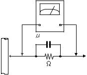
(5)Leakage shock hazard testing)
After reassembling the product, always perform an isolation check on the exposed metal parts of the product (antenna terminals, knobs, metal cabinet, screw heads, headphone jack, control shafts, etc.) to be sure the product is safe to operate without danger of electrical shock.Do not use a line isolation transformer during this check.
•Plug the AC line cord directly into the AC outlet. Using a "Leakage Current Tester", measure the leakage current from each exposed metal parts of the cabinet, particularly any exposed metal part having a return path to the chassis, to a known good earth ground. Any leakage current must not exceed 0.5mA AC (r.m.s.).
•Alternate check method
Plug the AC line cord directly into the AC outlet. Use an AC voltmeter having, 1,000 ohms per volt or more sensitivity in the following manner. Connect a 1,500 ohm 10W resistor paralleled by a 0.15 F AC-type capacitor between an exposed metal part and a known good earth ground.
Measure the AC voltage across the resistor with the AC voltmeter.
Move the resistor connection to each exposed metal part, particularly any exposed metal part having a return
path to the chassis, and measure the AC voltage across the resistor. Now, reverse the plug in the AC outlet and repeat each measurement. Voltage measured any must not exceed 0.75 V AC (r.m.s.). This corresponds to 0.5 mA AC (r.m.s.).
|
AC VOLTMETER |
|
(Having 1000 |
|
ohms/volts, |
|
or more sensitivity) |
0.15 F AC TYPE |
|
|
Place this |
|
probe on |
1500 10W |
each exposed |
metal part. |
|
Good earth ground
1.2Warning
(1)This equipment has been designed and manufactured to meet international safety standards.
(2)It is the legal responsibility of the repairer to ensure that these safety standards are maintained.
(3)Repairs must be made in accordance with the relevant safety standards.
(4)It is essential that safety critical components are replaced by approved parts.
(5)If mains voltage selector is provided, check setting for local voltage.
1.3Caution
Burrs formed during molding may be left over on some parts of the chassis.
Therefore, pay attention to such burrs in the case of preforming repair of this system.
1.4Critical parts for safety
In regard with component parts appearing on the silk-screen printed side (parts side) of the PWB diagrams, the parts that are printed over with black such as the resistor (  ), diode (
  ) and ICP (
  ) or identified by the "
 " mark nearby are critical for safety. When replacing them, be sure to use the parts of the same type and rating as specified by the manufacturer. (Except the JC version)
(No.YD118)1-3
1.5Preventing static electricity
Electrostatic discharge (ESD), which occurs when static electricity stored in the body, fabric, etc. is discharged, can destroy the laser diode in the traverse unit (optical pickup). Take care to prevent this when performing repairs.
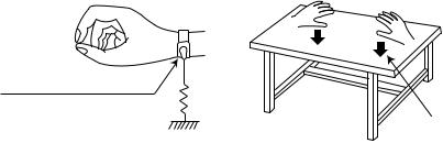
1.5.1Grounding to prevent damage by static electricity
Static electricity in the work area can destroy the optical pickup (laser diode) in devices such as DVD players. Be careful to use proper grounding in the area where repairs are being performed.
(1)Ground the workbench
Ground the workbench by laying conductive material (such as a conductive sheet) or an iron plate over it before placing the traverse unit (optical pickup) on it.
(2)Ground yourself
Use an anti-static wrist strap to release any static electricity built up in your body.
(caption)
Anti-static wrist strap
1M
Conductive material (conductive sheet) or iron palate
(3)Handling the optical pickup
•In order to maintain quality during transport and before installation, both sides of the laser diode on the replacement optical pickup are shorted. After replacement, return the shorted parts to their original condition.
(Refer to the text.)
•Do not use a tester to check the condition of the laser diode in the optical pickup. The tester's internal power source can easily destroy the laser diode.
1.6Handling the traverse unit (optical pickup)
(1)Do not subject the traverse unit (optical pickup) to strong shocks, as it is a sensitive, complex unit.
(2)Cut off the shorted part of the flexible cable using nippers, etc. after replacing the optical pickup. For specific details, refer to the
replacement procedure in the text. Remove the anti-static pin when replacing the traverse unit. Be careful not to take too long a time when attaching it to the connector.
(3)Handle the flexible cable carefully as it may break when subjected to strong force.
(4)I t is not possible to adjust the semi-fixed resistor that adjusts the laser power. Do not turn it.
1.7Precautions of the safe use of battery
•Store the battery in a place where children cannot reach.If a child accidentally swallows the battery, consult a doctorimmediately.
•Do not recharge, short, disassemble or heat the battery or dispose of it in a fire. Doing any of these things may cause the battery to give off heat, crack, or start a fire.
•Do not leave the battery with other metallic materials.Doing this may cause the battery to give off heat, crack, or start a fire.
•When throwing away or saving the battery, wrap it in tape and insulate; otherwise, the battery may start to give off heat, crack, or start a fire.
•Do not poke the battery with tweezers or similar tools.Doing this may cause the battery to give off heat, crack, or start a fire.
•Dispose of batteries in the proper manner, according to federal, state, and local regulations.
1-4 (No.YD118)
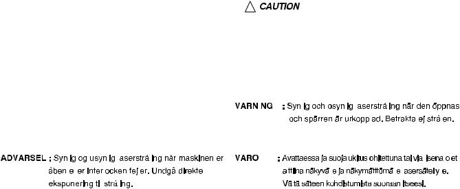
1.8Important for laser products
1.CLASS 1 LASER PRODUCT |
5.CAUTION : If safety switches malfunction, the laser is able |
|||||||||||||||||||||||||
2.CAUTION : VISIBLE AND/OR INVISIBLE CLASS 1M |
|
to function. |
|
|
|
|
|
|
|
|
|
|
|
|
|
|||||||||||
LASER RADIATION WHEN OPEN. |
6.CAUTION : Use of controls, adjustments or performance of |
|||||||||||||||||||||||||
DO NOT STARE INTO BEAM OR VIEW DIRECTLY WITH |
|
procedures other than those specified here in may result in |
||||||||||||||||||||||||
OPTICAL INSTRUMENTS. |
|
hazardous radiation exposure. |
||||||||||||||||||||||||
3.CAUTION : There are no serviceable parts inside the |
|
|
|
|
|
|
|
|
|
|
|
|
|
|
|
|
|
|
||||||||
Laser Unit. Do not disassemble the Laser Unit. Replace |
|
|
|
|
|
|
|
|
|
|
|
|
|
|
|
|
|
|
||||||||
|
! |
|
|
|
Please use enough caution not to |
|
||||||||||||||||||||
|
|
|
|
|
|
|
|
|
|
|
|
|
|
|||||||||||||
the complete Laser Unit if it malfunctions. |
|
|
|
|
|
|
|
|
|
|
|
|
|
|
|
|
|
|||||||||
|
|
|
|
|
see the beam directly or touch it |
|
||||||||||||||||||||
4.CAUTION : The laser products uses visible and / or |
|
|
|
|
|
in case of an adjustment or operation |
|
|||||||||||||||||||
invisible laser radiation and is equipped with safety |
|
|
|
|
|
check. |
|
|||||||||||||||||||
|
|
|
|
|
|
|
|
|
|
|
|
|
|
|
|
|
|
|||||||||
switches which prevent emission of radiation when the |
|
|
|
|
|
|
|
|
|
|
|
|
|
|
|
|
|
|
||||||||
drawer is open and the safety interlocks have failed or are |
|
|
|
|
|
|
|
|
|
|
|
|
|
|
|
|
|
|
||||||||
defeated. It is dangerous to defeat the safety switches. |
|
|
|
|
|
|
|
|
|
|
|
|
|
|
|
|
|
|
||||||||
|
|
|
|
|
|
|
|
|
|
|
|
|
|
|
|
|
|
|
|
|
|
|
|
|
|
|
CAUTION : VISIBLE AND/OR INVISIBLE CLASS 1M |
|
|
|
|
|
|
|
|
|
|
|
|
|
|
|
|
|
|
||||||||
|
|
|
|
|
|
|
|
|
|
|
|
|
|
|
|
|
|
|||||||||
|
|
|
|
|
|
|
|
|
|
|
|
|
|
|
|
|
|
|||||||||
LASER RADIATION WHEN OPEN. |
|
|
|
|
|
|
|
|
|
|
|
|
|
|
|
|
|
|
||||||||
|
|
|
|
|
|
|
|
|
|
|
|
|
|
|
|
|
|
|||||||||
|
|
|
|
|
|
|
|
|
|
|
|
|
|
|
|
|
|
|||||||||
DO NOT STARE INTO BEAM OR VIEW |
|
|
|
|
|
|
|
|
|
|
|
|
|
|
|
|
|
|
||||||||
DIRECTLY WITH OPTICAL INSTRUMENTS. |
|
|
|
|
|
|
|
|
|
|
|
|
|
|
|
|
|
|
||||||||
|
|
|
|
|
|
|
|
|
|
|
|
|
|
|
|
|
|
|
|
|
|
|
|
|
|
|
|
|
|
|
|
|
|
|
|
|
|
|
|
|
|
|
|
|
|
|
|
|
|
|
|
|
|
|
|
|
|
|
|
|
|
|
|
|
|
|
|
|
|
|
|
|
|
|
|
|
|
|
|
|
|
|
|
|
|
|
|
|
|
|
|
|
|
|
|
|
|
|
|
|
|
|
|
|
|
|
|
|
|
|
|
|
|
|
|
|
|
|
|
|
|
|
|
|
|
|
|
|
|
|
|
|
|
|
|
|
|
|
|
|
|
|
|
|
|
|
|
|
|
|
|
|
|
|
|
|
|
|
|
|
|
|
|
|
|
|
|
|
|
|
|
|
|
|
|
|
|
|
|
|
|
|
|
|
|
|
|
|
(No.YD118)1-5
SECTION 2
SPECIFIC SERVICE INSTRUCTIONS
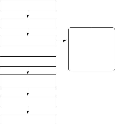
2.1SERVICE INFORMATION FOR EEPROM
POWER ON
DVD LOGO Status (NO Disk status)
Remotecontrol
Pause key-->1-->4-->7-->2 in order.
Press number 0~8, Press charater
A~F (1~6 for a while)
Use arrow key (F D G E) to move to approprite position and make changes
DETECT NEW EEPROM (OPTION EDIT SCREEN)
MODEL : XV-N450B/XV-N452S
NAME |
HEX |
OPT 1 |
00 |
OPT 2 |
00 |
OPT 3 |
00 |
OPT 4 |
00 |
OPT 5 |
00 |
OPT 6 |
00 |
OPT 7 |
00 |
OPT 8 |
00 |
Press pause key once
Change will be applied when power OFF-->ON.
1-6 (No.YD118)
SECTION 3
DISASSEMBLY
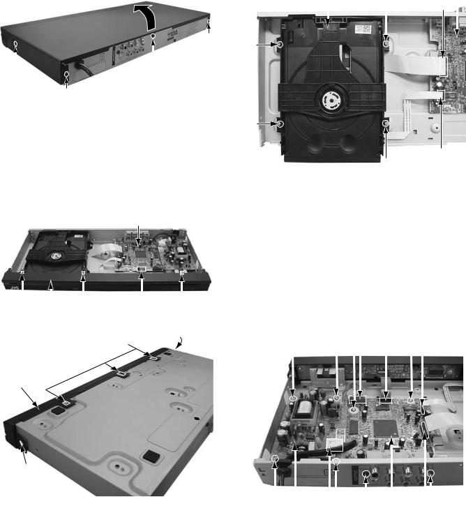
3.1Main body section
3.1.1 Removing the top cover (See figure 1)
(1)Remove the two screws A attaching the top cover on both sides of the main body.
(2)Remove the three screws B attaching the top cover on the back of the main body.
(3)Raise the both sides and lower part of the rear of the top cover, with opening them slightly in an outward direction. And the top cover will be removed.
TOP COVER
B
A |
|
|
|
|
|
|
|
x 2 |
B |
||
B
Fig.1
3.1.2 Removing the front panel assembly (See figure 2, figure 3)
•Prior to performing the following procedure, remove the top cover.
(1)Disconnect the card wire from connector P6901 on the main board.
(2)Remove the eight hooks a, and then remove the front panel assembly.
Main board
|
|
|
|
|
|
|
|
|
|
|
|
|
|
|
|
|
|
|
|
|
Hook a |
Hook a |
P6901 Hook a |
||||
Front panel assembly |
|
|
|
|||
|
|
|
Fig.2 |
|
|
|
|
|
|
Hook a |
|
Hook a |
|
|
|
|
|
|
|
|
Front panel assembly
Hook a
Fig.3
3.1.3 Removing the mechanism assembly (See figure 4)
•Prior to performing the following procedure, remove the top cover and front panel assembly.
(1)Disconnect the card wire from connectors P2201 and P2202 on the main board.
(2)Remove the four screws C attaching the mechanism assembly.
Mechanism |
assembly |
|
|
Main board |
|
C |
P2201 |
|
|||
|
|
|
|
|
|
|
|
|
|
|
|
|
|
|
|
|
|
C
C
P2202
C
Fig.4
3.1.4 Removing the regulator board and main board (See figure 5)
•Prior to performing the following procedure, remove the top cover.
(1)Disconnect the wire from connector PW6101 on the main board.
(2)Disconnect the power cord from connector PW101 on the regulator board.
(3)Remove the four screws D attaching the regulator board.
(4)Disconnect the card wire from connectors P2201, P2202, and P6901 on the main board.
(5)Remove the two screws E attaching the main board.
(6)Remove the two screws F attaching the main board with rear panel.
|
|
|
PW6101 |
|
P2202 |
||||
D |
D E |
P6901 |
E |
|
|||||
|
|
|
|
|
|
|
|
|
|
|
|
|
|
|
|
|
|
|
|
|
|
|
|
|
|
|
|
|
|
|
|
|
|
|
|
|
|
|
|
|
|
|
|
|
|
|
|
|
|
|
|
|
|
|
|
|
|
|
|
|
|
|
|
|
|
|
|
|
|
|
|
|
|
|
|
|
|
|
|
|
|
|
|
|
|
|
|
|
|
|
|
|
|
|
|
D |
|
D |
F Main board |
F |
||||||
|
||||||||||
|
|
PW101 |
|
|
P2201 |
|||||
Regulator board |
|
|
||||||||
Fig.5 |
||||||||||
|
|
|
|
|
||||||
|
|
|
|
|
|
|
(No.YD118)1-7 |
|||

3.2 DVD MECHANISM PARTS LOCATION
• TOP VIEW (WITH TRAY)
• TOP VIEW (WITHOUT TRAY)
• BOTTOM VIEW
Procedure |
|
Parts |
|
Fixing Type |
Disass |
Fig- |
|
Starting No. |
|
|
|
embly |
ure |
||
|
|
|
|
|
|||
|
|
|
|
|
|
|
|
|
|
|
|
|
|
|
|
|
|
1 |
Main Base |
|
|
|
4-1 |
|
|
|
|
|
|
|
|
1 |
|
2 |
Clamp Assem- |
|
|
|
4-1 |
|
|
|
bly Disc |
|
|
|
|
1, 2 |
|
3 |
Plate Clamp |
|
|
|
4-1 |
|
|
|
|
|
|
|
|
1, 2, 3 |
|
4 |
Magnet Clamp |
|
|
|
4-1 |
|
|
|
|
|
|
|
|
1, 2, 3, 4 |
|
5 |
Clamp Upper |
|
|
|
4-1 |
|
|
|
|
|
|
|
|
1 |
|
6 |
Tray Disc |
|
|
|
4-2 |
|
|
|
|
|
|
|
|
1, 6 |
|
7 |
Base Assembly |
|
|
|
4-3 |
|
Sled |
|
|
|
|||
|
|
|
|
|
|
|
|
|
|
|
|
4 |
Screws, |
|
|
1, 2, 6 |
|
8 |
Gear Feed |
1 |
Connector |
|
4-3 |
|
|
|
|
1 Locking Tabs |
|
|
|
1, 2, 6, 8 |
|
9 |
Gear Middle |
|
|
|
|
|
|
|
|
|
|
|
|
1, 2, 6, 8,9 |
|
10 |
Gear Rack |
1 |
Screw |
|
4-3 |
|
|
|
|
|
|
|
|
1, 2, 7 |
|
11 |
Rubber Rear |
|
|
|
4-3 |
|
|
|
|
|
|
|
|
1, 2, 7 |
|
12 |
Frame Assem- |
1 |
Screw |
Bottom |
4-4 |
|
bly Up/Down |
||||||
|
|
|
|
|
|
|
|
1, 2 |
|
13 |
Belt Loading |
1 |
Locking Tab |
|
4-4 |
|
|
|
|
|
|
|
|
1, 2 ,13 |
|
14 |
Gear Pulley |
|
|
|
4-4 |
|
|
|
|
|
|
|
|
1, 2, 13, 14 |
|
15 |
Gear Loading |
1 |
Locking Tab |
|
4-4 |
|
|
|
|
|
|
|
|
1, 2, 7, 12, |
|
16 |
Guide Up/Down |
|
|
|
4-4 |
13, 14 |
|
|
|
|
|
|
|
|
|
|
PWB Assembly |
1 |
Locking Tab |
|
|
1, 2, 13 |
|
17 |
1 |
Hook |
Bottom |
4-4 |
|
|
|
|
Loading |
2 |
Screw |
|
|
|
|
|
|
|
|
||
|
|
|
|
|
|
|
|
1,2,7,12,13, |
|
18 |
Base Main |
2 Locking Tabs |
|
4-4 |
|
14,15,16,17 |
|
|
|
|
|
|
|
Note
When reassembling, perform the procedure in reverse order. The “Bottom” on Disassembly column of above Table indicates the part should be disassembled at the Bottom side.
1-8 (No.YD118)
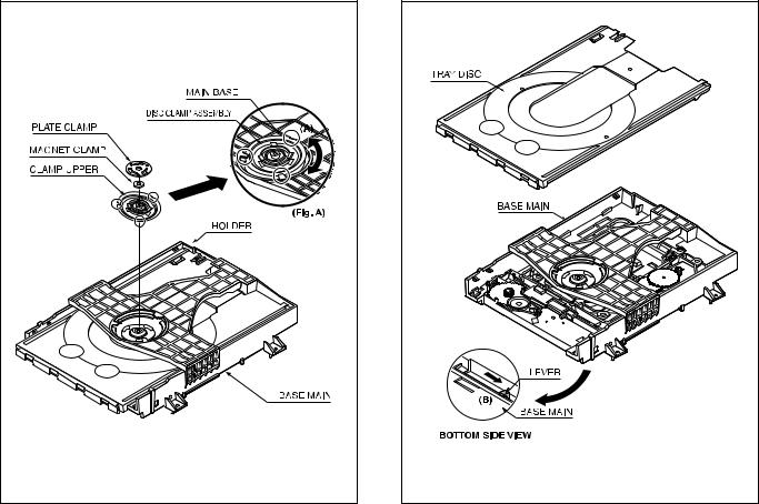
3.3DVD MECHANISM DISASSEMBLY
Fig.4-1 |
3.3.1 MAIN BASE (FIG. 4-1)
3.3.1.1Clamp Assembly Disc
(1)Place the Clamp Assembly Disc as Fig. (A)
(2)Lift up the Clamp Assembly Disc in direction of arrow(A).
(3)Separate the Clamp Assembly Disc from the Holder Clamp.
3.3.1.1.1Plate Clamp
(1) Turn the Plate Clamp to counterclockwise direction and then lift up the Plate Clamp.
3.3.1.1.2Magnet Clamp
3.3.1.1.3Clamp Upper
Fig.4-2 |
3.3.2 TRAY DISC (FIG. 4-2)
(1)Insert and push a Driver in the emergency eject hole(A) at the right side, or put the Driver on the Lever(B) of the Gear Emergency and pull the Lever(B) in direction of arrow so that the Tray Disc is ejected about 15~20mm.
(2)Pull the Tray Disc until it is separated from the Base Main completely.
(No.YD118)1-9
Loading...