


Model 4510
Conductivity/TDS Meter
Operating Manual
451 050/REV A/03-03
SAFETY
Please read this information carefully prior to installing or using this equipment.
1. The unit described in this manual is designed to be operated only by trained personnel. Any adjustments, maintenance and repair must be carried out as defined in this manual, by a person qualified to be aware of the hazards involved.
2.It is essential that both operating and service personnel employ a safe system of work, in addition to the detailed instructions specified in this manual.
3.References should always be made to the Health and Safety data supplied with any chemicals used. Generally accepted laboratory procedures for safe handling of chemicals should be employed.
4.If it is suspected that safety protection has been impaired in any way, the unit must be made inoperative and secured against any intended operation. The fault condition should immediately be
reported to the appropriate servicing authority.
451 050/REV A/03-03
Model 4510
Conductivity/TDS Meter
Operating Manual
Contents |
|
|
Section 1 |
Introduction |
|
|
Instrument Description |
1.1 |
|
Instrument Specification |
1.2 |
Section 2 |
Installation |
|
|
Unpacking |
2.1 |
|
Installation |
2.2 |
|
Displays |
2.3 |
|
Controls |
2.4 |
|
Inputs/Outputs |
2.5 |
Section 3 |
Operation |
|
|
Good Practice Guidelines |
3.1 |
|
Instrument Set up |
3.2 |
|
Preparation of Standards |
3.3 |
|
Calibration: |
|
|
With Known Cell Constant |
3.4 |
|
With Standard Solution |
3.5 |
|
Sample Measurement |
3.6 |
Section 4 |
Maintenance |
|
|
General |
4.1 |
Section 5 |
Optional Accessories |
|
|
Optional Accessories |
5.1 |
|
Spares |
5.2 |
Section 6 |
Interfacing |
|
|
Analogue |
6.1 |
|
RS232 |
6.2 |
|
Keypad Emulation |
6.3 |
|
Printing |
6.4 |
Section 7 |
Troubleshooting |
|
k |
Troubleshooting |
7.1 |
451 050/REV A/03-03
Section 1
Introduction
1.1 Instrument Description
A general purpose Conductivity/TDS/temperature bench meter for use in laboratory situations. The instrument includes a 32 reading memory facility. Features include: automatic range selection, calibration on standard solutions or direct cell constant entry, automatic temperature compensation, analogue output and RS232 serial interface.
1.2 Instrument Specifications |
|
Conductivity |
|
Ranges |
0 to 19.99µS / 0 to 199.9µS / 0 to 1999µS / |
|
0 to 19.99mS / 0 to 199.9mS / 0 to 1999mS |
Resolution |
0.01µS / 0.1µS / 1µS / 0.01mS / 0.1mS / 1mS* |
|
*only with cell constant >5 |
Accuracy |
±0.5%±2 digits |
TDS |
|
Ranges |
0 to 19.99mg/l / 0 to 199.9mg/l / 0 to 1999mg/l / |
|
0 to 19.99g/l / 0 to 199.9g/l / 0 to 1999g/l |
Resolution |
0.01mg/l / 0.1mg/l / 1mg/l / 0.01g/l / 0.1g/l / 1g/l* |
|
*only with cell constant >5 |
Accuracy |
±0.5%±2 digits |
Temperature |
|
Range |
-10 to +105°C (14 to 221°F) |
Resolution |
0.1°C (1°F) |
Accuracy |
±0.5°C (±1°F) |
ATC Range |
0 to 100°C (32 to 212°F) |
Manual Temp. Comp. Range |
0 to 100°C (32 to 212°F) |
Display |
3½ digit LCD |
Power |
9V power supply |
Size |
210x250x55mm |
Weight |
850g |
1 |
451 050/REV A/03-03 |
|

Section 2
Installation
2.1 Unpacking
Remove the Model 4510 from the packaging and ensure the following items are included:
1.Model 4510 Conductivity/TDS Meter
2.Glass bodied conductivity cell with ATC K=1 (027 013)
3.Electrode holder
4.Power Supply (as specified at time of ordering the product)
5.Condensed operating instructions (451 051)
6.Operating Manual (451 050)
The electrode stand requires minimal assembly (refer to the diagram below)
Any shortages or damage should be reported immediately to the manufacturer or your local distributor.
2.2 Installation
The Model 4510 is supplied ready to use. Connect the conductivity cell to the rear panel DIN socket.
The electrode stand requires minimal assembly (refer to the diagram below).
Fig. 2.2.1 Electrode Holder Assembly

 4 1
4 1 


2
3
2 |
451 050/REV A/03-03 |

2.3 Displays
1.Standard selection – indicates which type of standard is being used. Also indicates when a calibration is being performed.
2.Symbol – displayed during set-up of instrument parameters.
3.Primary display – 4½ digit. Provides direct readout in Conductivity or TDS of samples and standards.
4.Mode annunciators – shows selected measurement mode; Conductivity (µS or mS) and TDS (mg/l or g/l).
5.Endpoint symbol
6.Secondary display – 6 digit display. Provides direct readout of automatic or manual temperature. Scrolls and displays selected parameter information in set-up mode.
7.Status display – 2½ digit.
8.Mode annunciators – indicates temperature in °C or °F and whether the measurements are manually or automatically temperature compensated.
9.Mode tags – Each mode tag is highlighted when selected; SETUP, MODE or RESULTS.
3 |
451 050/REV A/03-03 |
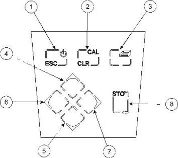
2.4 Keypad
1. ESC |
used to switch the instrument on and to place into standby mode (only if power |
|
|
|
supply lead remains connected to the instrument). Also used to escape/exit a |
|
|
mode. |
2. |
CAL / CLR |
used to select and perform a calibration sequence. This key is also used to clear |
|
|
readings from Memory. |
3. |
Print key |
used to initiate a print. |
4. Up Arrow |
used for adjustment during set up, to scroll results and to toggle between |
|
|
|
Conductivity (µS or mS) and TDS (mg/l or g/l) modes. |
5. |
Down Arrow |
used for adjustment during set up, to scroll results and to toggle between |
|
|
Conductivity µS or mS) and TDS (mg/l or g/l) modes. |
6. Left Arrow |
used for adjustment during set up and to move between mode tags. |
|
7. |
Right Arrow |
used for adjustment during set up and to move between mode tags. |
8. STO |
used to accept an entered value in set-up mode and to instigate a stored reading. |
|
|
|
This key can also be used as a CAL key during calibration. |
4 |
451 050/REV A/03-03 |
 Loading...