


Spectrophotometer 7410,7415 and 7615
Instruction Manual
JEN0001 / Version 1.2
Contents
Section 1 - Introduction.................................................................................. |
6 |
||
1.1 |
General Description....................................................................................................... |
6 |
|
1.2 |
Important Safety Advice................................................................................................. |
6 |
|
1.3 |
Symbols Defined........................................................................................................... |
6 |
|
1.4 |
Electrical Requirements.................................................................................................. |
7 |
|
Section 2 - Installation................................................................................... |
8 |
||
2.1 |
Unpacking..................................................................................................................... |
8 |
|
2.2 |
Installation Conditions................................................................................................... |
8 |
|
2.3 |
Overview...................................................................................................................... |
9 |
|
Section 3 - Theory and Practice of Spectroscopy Measurement..................... |
10 |
||
|
|
|
|
3.1 |
Theory of Spectroscopy Measurement............................................................................. |
10 |
|
3.2 |
Spectroscopy Measurement............................................................................................ |
11 |
|
3.3 |
Good Practice Guidelines................................................................................................ |
12 |
|
Section 4 - Instrument Set up........................................................................ |
14 |
||
|
|
|
|
4.1 |
Start up Screen............................................................................................................. |
14 |
|
4.2 |
Navigation.................................................................................................................... |
14 |
|
4.3 |
Methods....................................................................................................................... |
16 |
|
4.4 |
Results......................................................................................................................... |
16 |
|
4.5 |
Settings........................................................................................................................ |
16 |
|
4.5.1 |
|
Instrument Status.................................................................................................... |
16 |
4.5.1.1 |
Instrument Language......................................................................................... |
16 |
|
4.5.1.2 |
Setting the Time................................................................................................ |
17 |
|
4.5.1.3 |
Setting the Date................................................................................................ |
17 |
|
4.5.1.4 |
Setting the Time Zone= |
18 |
|
4.5.2 |
|
Measurement Settings............................................................................................. |
18 |
4.5.3 |
|
Network Connections............................................................................................... |
19 |
4.5.4 |
|
Storage................................................................................................................... |
19 |
4.5.5 |
|
Service Settings....................................................................................................... |
19 |
Section 5 - Photometrics................................................................................. |
20 |
||
|
|
|
|
5.1 |
Method Set up.............................................................................................................. |
20 |
|
5.1.1 |
|
Selecting a Wavelength............................................................................................ |
20 |
5.2 |
Calibration.................................................................................................................... |
21 |
|
5.3 |
Sample Measurement.................................................................................................... |
21 |
|
Section 6 - Concentration...............................................................................
4
|
|
|
22 |
6.1 |
Method Set up.............................................................................................................. |
22 |
|
6.1.1 |
|
Selecting a Wavelength............................................................................................ |
22 |
6.1.2 |
|
Using a Factor......................................................................................................... |
22 |
6.1.3 |
|
Using a Standard..................................................................................................... |
23 |
6.1.4 |
|
Selecting Concentration Units................................................................................... |
23 |
6.2 |
Calibration.................................................................................................................... |
23 |
|
6.2.1 |
|
Calibrating to a Factor.............................................................................................. |
24 |
6.2.2 |
|
Calibrating to a Standard.......................................................................................... |
24 |
6.3 |
Sample Measurement.................................................................................................... |
25 |
|
6.3.1 |
|
Measuring a Sample After Calibrating to a Factor....................................................... |
25 |
6.3.2 |
|
Measuring a Sample After Calibrating to a Standard................................................... |
25 |
Section 7 - Spectrum....................................................................................... |
26 |
||
|
|
|
|
7.1 |
Method Set up.............................................................................................................. |
26 |
|
7.1.1 |
|
Setting Start and End Wavelengths........................................................................... |
26 |
7.1.2 |
|
Setting the Scan Interval.......................................................................................... |
27 |
7.1.3 |
|
Selecting Absorbance or % Transmittance................................................................. |
27 |
7.2 |
Calibration.................................................................................................................... |
27 |
|
7.3 |
Sample Measurement.................................................................................................... |
27 |
|
7.4 |
Data Analysis................................................................................................................ |
28 |
|
7.4.1 |
|
Peaks and Valleys.................................................................................................... |
28 |
7.4.2 |
|
Area Under Curve.................................................................................................... |
29 |
7.4.2.1 |
Area Under Curve - Baseline Mode...................................................................... |
29 |
|
7.4.2.2 |
Area Under Curve - Tangent Mode...................................................................... |
30 |
|
Section 8 - Quantitation.................................................................................. |
31 |
||
|
|
|
|
8.1 |
Method Set up.............................................................................................................. |
31 |
|
8.1.1 |
|
Selecting a Wavelength............................................................................................ |
31 |
8.1.2 |
|
Selecting Number of Replicates................................................................................. |
32 |
8.1.3 |
|
Selecting Concentration Units................................................................................... |
32 |
8.2 |
Measuring Calibration Standards..................................................................................... |
33 |
|
8.3 |
Standard Curve............................................................................................................. |
34 |
|
8.4 |
Sample Measurement.................................................................................................... |
35 |
|
Section 9 - Kinetics......................................................................................... |
36 |
||
|
|
|
|
9.1 |
Method Set up.............................................................................................................. |
36 |
|
9.1.1 |
|
Selecting a Wavelength............................................................................................ |
36 |
9.1.2 |
|
Setting the Kinetics Measurement Time..................................................................... |
37 |
5
9.1.3 |
Setting the Measurement Time Interval..................................................................... |
37 |
|
9.1.4 |
Setting Lag Time..................................................................................................... |
37 |
|
9.1.5 |
Selecting Absorbance or % Transmittance................................................................. |
37 |
|
9.1.6 |
End Point Concentration........................................................................................... |
37 |
|
9.2 |
Calibration.................................................................................................................... |
38 |
|
9.3 |
Sample Measurement.................................................................................................... |
38 |
|
9.4 |
Data Analysis................................................................................................................ |
40 |
|
Section 10 - Multi-Wavelength....................................................................... |
41 |
||
|
|
|
|
10.1 |
Method Set up.............................................................................................................. |
41 |
|
10.1.1 |
Selecting a Wavelength............................................................................................ |
41 |
|
10.1.2 |
Equation Parameters................................................................................................ |
42 |
|
10.1.2.1 |
Entering a Factor............................................................................................... |
43 |
|
10.1.2.2 |
Selecting Concentration Units............................................................................. |
43 |
|
10.1.3 |
Selecting Absorbance or % Transmittance................................................................. |
43 |
|
10.2 |
Calibration.................................................................................................................... |
44 |
|
10.3 |
Sample Measurement.................................................................................................... |
44 |
|
Section 11 - Saving, Loading, Deleting and Printing...................................... |
45 |
||
|
|
|
|
11.1 |
Saving Methods............................................................................................................. |
45 |
|
11.1.1 |
Saving Methods to Internal Memory.......................................................................... |
45 |
|
11.1.2 |
Saving Methods to CPLive........................................................................................ |
45 |
|
11.1.3 |
Saving Methods to USB Memory Stick....................................................................... |
45 |
|
11.2 |
Loading Methods........................................................................................................... |
45 |
|
11.2.1 |
Loading Methods from Internal Memory.................................................................... |
45 |
|
11.2.2 |
Loading Methods from USB Memory Stick.................................................................. |
45 |
|
11.3 |
Deleting Methods.......................................................................................................... |
45 |
|
11.4 |
Saving Results............................................................................................................... |
46 |
|
11.4.1 |
Saving Results to Internal Memory............................................................................ |
46 |
|
11.4.2 |
Saving Results to CPLive.......................................................................................... |
46 |
|
11.4.3 |
Saving Results to USB Memory Stick......................................................................... |
46 |
|
11.5 |
Loading Results............................................................................................................. |
46 |
|
11.5.1 |
Loading Results from Internal Memory...................................................................... |
46 |
|
11.5.2 |
Loading Results from USB Memory Stick.................................................................... |
46 |
|
11.6 |
Deleting Results............................................................................................................ |
46 |
|
11.7 |
Printing......................................................................................................................... |
|
46 |
Section 12 - Accessories and Spare Parts....................................................... |
47 |
||
|
|
|
|
12.1 |
Optional Accessories...................................................................................................... |
47 |
|
6
12.2 |
Installing the Accessories............................................................................................... |
47 |
||
12.2.1 |
Passive Accessories.................................................................................................. |
47 |
||
12.2.2 |
Active Accessories................................................................................................... |
48 |
||
12.2.2.1 |
Installing Automatic 8 Cell Turret........................................................................ |
49 |
||
12.3 |
Using the Accessories.................................................................................................... |
50 |
||
12.3.1 |
Automatic 8 Cell Turret............................................................................................ |
50 |
||
12.3.1.1 |
Automatic 8 |
Cell Turret - Manual Mode................................................................ |
50 |
|
12.3.1.2 |
Automatic 8 |
Cell Turret - Automatic Mode............................................................ |
52 |
|
12.3.1.3Automatic 8 Cell Turret - Supporting Creation of a Standard Curve in Quantitation.. 54
12.4 |
Spare Parts................................................................................................................... |
54 |
Section 13 - Maintenance, Servicing and Cleaning......................................... |
|
|
|
|
55 |
13.1 |
Routine Maintenance..................................................................................................... |
55 |
13.2 |
Lamp Replacement........................................................................................................ |
57 |
13.2.1 |
Tungsten Halogen Lamp Replacement....................................................................... |
57 |
13.2.2 |
Xenon Lamp Module Replacement............................................................................ |
58 |
13.3 |
Service, Repairs and Support.......................................................................................... |
58 |
13.4 |
Warranty....................................................................................................................... |
58 |
Section 14 - Environmental Protection........................................................... |
|
|
|
|
58 |
14.1 |
Packaging Material......................................................................................................... |
58 |
14.2 |
Waste Electrical and Electronic Equipment Directive (WEEE)............................................. |
58 |
Section 15 - Technical Specification............................................................... |
|
|
|
|
59 |
15.1 |
General Specification..................................................................................................... |
59 |
15.2 |
Weights and Dimensions................................................................................................ |
60 |
Section 16 - Troubleshooting.......................................................................... |
|
|
|
|
61 |
Section 17 - Glossary of Icons........................................................................ |
|
|
|
|
63 |
Index............................................................................................................... |
|
|
|
|
64 |
Declaration of Conformity............................................................................... |
|
|
|
|
67 |
7

Section 1 - Introduction
Thank you for purchasing this Jenway product. To get the best performance from the equipment, and for your own safety, please read these instructions carefully before use.
If the equipment is not used in the manner described in this manual and with accessories other than those recommended by the manufacturer, the protection provided may be impaired.
1.1General Description
The 7410, 7415 and 7615 spectrophotometers are suited to a wide range of applications in education, quality control, environmental and clinical analysis. The 7410 is a visible spectrophotometer covering a wavelength range from 320nm to 1000nm. The 7415 and 7615 are UV/Visible spectrophotometers with a wavelength range from 198nm to 1000nm. All models have measurement modes for Photometrics, Concentration, Spectrum scanning, Multi-wavelength, Quantitation and Kinetics. All models are compatible with CPLive.
1.2Important Safety Advice
Users should be aware of the following safety advice:
●SHOCK HAZARDS OR UNSAFE PRACTICES ARE DANGEROUS as they can cause severe personal injury, fire or death.
●DO NOT use combustible substances near hot objects.
●DO NOT use the equipment in hazardous atmospheres.
●DONOToperateorhandleanypartoftheequipmentwithwethandsoruseonsurfacesthatmaybecomeflooded.
●NEVER move the equipment while still connected to the power supply.
●HIGH TEMPERATURES ARE DANGEROUS as they can cause serious burns to operators and ignite combustible material.
●USE CARE AND WEAR PROTECTIVE GLOVES TO PROTECT HANDS.
●NEVER lift or carry the equipment during operation.
●DO NOT position the equipment unit so that it is difficult to disconnect from the mains supply using the mains plug.
●The mains outlet socket used should be located close to the equipment and readily identifiable and accessible to users.
●DO NOT leave equipment switched on and it is not recommended to leave any heating apparatus unattended during operation.
●The equipment should be carried using both hands.
1.3Symbols Defined
BIOHAZARD |
EARTH |
HOT |
INFORMATION |
RISK OF |
UV LIGHT |
WARNING |
|
|
SURFACE |
|
ELECTRIC |
SOURCE |
|
|
|
|
|
SHOCK |
|
|
8

1.4Electrical Requirements
THIS INSTRUMENT MUST BE GROUNDED
Before connection please ensure that the line supply corresponds to the power requirements below:
Power |
Supply requirements |
65 W |
100 V - 230 V ~ 50/60 Hz |
The equipment is provided with a power supply unit and three power cables consisting of a UK 3-pin and a “Schuko” 2-pin plug for 230 V installations and a NEMA 5-15 plug for 120 V installations.
Choose the power cable appropriate for your electrical installation and discard the others. Should one of the power cables be suitable for connecting to the power supply, replace the plug with a suitable alternative..
THIS OPERATION SHOULD ONLY BE UNDERTAKEN BY A QUALIFIED ELECTRICIAN.
NOTE: Refer to the equipment rating plate to ensure that the plug and fusing are suitable for the voltage and wattage stated. The wires in the mains cable are as follows:
230 V a.c. |
120 V a.c. |
HOT/LIVE - BROWN |
BLACK - HOT/LIVE |
NEUTRAL - BLUE |
WHITE - NEUTRAL |
EARTH - GREEN/YELLOW |
GREEN - EARTH |
The appropriate power cable and power adaptor combination should be connected to the equipment BEFORE connection to the mains supply. Should the mains lead require replacement, a cable of 1.25mm² (AWG16) of harmonised code H05VV-F connected to an IEC320 plug should be used.
IF IN DOUBT CONSULT A QUALIFIED ELECTRICIAN
9
Section 2 - Installation
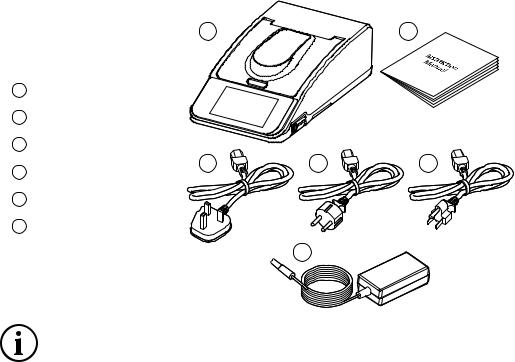
2.1Unpacking
Before discarding the packaging check that all parts are present and correct.
17410 / 7415 / 7615
2Instruction manual
3UK power lead
4EU power lead
5US power lead
6Power supply unit
2.2Installation Conditions
1 |
2 |
3 |
4 |
5 |
6
When the equipment is used for the first time or moved to a different environmental temperature, it is important to allow the equipment to equalise to the ambient temperature. We recommend you allow the equipment to stand for 2 hours before switching on.
This equipment is designed to operate safely under the following conditions:
●For indoor use only
●Use in a well ventilated area
●Ambient temperature range 5°C to 40°C (41°F to 104°F)*
●Altitude to 2000m (6500 ft)
●Relative humidity not exceeding 80% (temperature 31ºC) decreasing to 50% (temperature 40ºC) and free from condensation
●Mains supply fluctuations not exceeding 10% of nominal
●Overvoltage category
●Pollution degree 2
●Use with a minimum distance all round of 300mm (12in.) from walls or other items
Place the equipment on a clean, firm, level surface which is free from drafts. Avoid installation on a slippery surface or on a surface prone to vibration or on a surface prone to flooding.
Select the power lead and attach to the power supply unit. Connect the power supply unit to the power inlet socket on the rear panel of the instrument and connect to the mains socket. Ensure that the sample chamber is empty before turning the power on at the mains and switching the instrument on using the power switch on the side of the instrument.
The equipment will perform several power-on tests and wavelength calibration before displaying the main screen. NOTE: 7410 must be switched on 30 minutes before any readings are performed to allow the tungsten lamp to
warm up
NOTE: Leaving cuvettes in the sample holder during power up will result in failure of the power on tests.
10

2.3Overview
Main View
1 |
Lid |
1 |
2 |
Open and close catch |
2 |
|
|
|
3 |
Colour touchscreen |
|
|
and user interface |
|
4 |
Removable panel |
3 |
|
for sipper accessory |
|
5 |
2 x USB Type A ports |
|
6 |
On/Off power switch |
|
Rear View
7 |
Ethernet (RJ-45) port |
|
8 |
USB Type B port |
|
9 |
Power inlet socket |
7 |
|
|
|
|
|
8 |
9 |
Underneath View
10 Lamp holder cover
4 |
5
6 |
4 |
10 |
Refer to Section 13.2 for instructions on how to remove and replace the lamp.
11
Section 3 - Theory and Practice of Spectroscopy Measurement
3.1Theory of Spectroscopy Measurement
UV-visible spectroscopy is the measurement of the absorbance of light at a specific wavelength in a sample. This is used to identify the presence and concentration of molecular entities within the sample. The Beer-Lambert law is used to relate the absorption of light to the properties of the sample through which the light is travelling through. The Beer-Lambert law states that:
A = Ɛ l c
A is the absorbance
Ɛis the molar absorption coefficient (l mol-1cm-1)
lis the path length (cm)
cis the concentration (mol I-1)
This law shows that absorbance is linear to concentration but this is only true for low concentrations. For absorbance levels above 3 the concentration starts to move away from the linear relationship.
Transmittance is the proportion of the light which passes through the sample:
|
|
|
|
Where: |
|
|
|
|
|
lo |
is the incident light |
l |
Io |
|
It |
t |
is the transmitted light |
|
|
|
|||
|
|
|
|
l |
is the path length |
|
|
|
|
|
|
|
|
I |
|
|
|
Therefore: |
|
|
|
|
|
T = It Io
Absorbance is inversely related to transmittance:
A = Log 1
T
12
3.2Spectroscopy Measurement
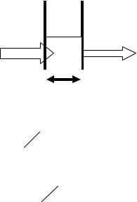
There are four main components of a spectrophotometer. These are a light source to emit a high and constant amount of energy over the full wavelength range; a method for separating the light into discreet wavelengths; a sample holder and a light detector.
The optical layout of the 7410 and 7415 spectrophotometers is shown below:
Entrance Slit
Lamp |
|
|
|
|
Grating |
|
|
|
|
|
|
|
|
|
|
|
|
|
|
|
|
|
|
|
|
|
|
|
|
|
|
|
|
|
|
|
Collimator Mirror |
Exit Slit |
|
Sample |
Detector |
|
Collecting Lens |
The light from the pre-focused tungsten halogen (7410) or pre-aligned xenon (7415) lamp is focused onto the grating, with 1200 lines per millimetre, which separates the light into discrete wavelengths. The diffracted spectrum of light then passes through a further slit and lens arrangement before passing through the sample in the sample chamber from left to right. The light which is not absorbed by the sample is transmitted through a collecting lens and onto the signal detector. The photo-diode detector used is mounted directly onto the detector PCB and the output is used to calculate the % transmittance. The result is displayed either as % transmittance or absorbance on the instrument display.
Note:
On the 7615 model an additional detector at the exit slit detects the incident light and noise through the optical system
13
3.3Good Practice Guidelines
1.For optimum performance all spectrophotometers should be sited in a clean, dry, dust free atmosphere. When in use ambient temperature and light levels should remain as constant as possible.
2.If required adherence to Standard Operating Procedures (SOP) and Good Laboratory Practice (GLP) should be monitored with regular calibration checks and a suitable Quality Control (QC) programme.
3.The sample chamber lid must be fully closed during measurement and before any readings are recorded or printed.
4.The correct selection of sample containers is imperative for accurate and reproducible results:
a)Check that the material of the sample container is compatible with the wavelengths to be used for measurement. In general glass can only be used down to 360nm or 320nm depending on quality. Standard plastic cuvettes can be used down to 320nm. Special UV versions can be used down to 260nm.
Below this level quartz cuvettes must be used.
b)Plastic disposable cuvettes should only be used ONCE.
c)Glass cuvettes should be thoroughly cleaned after use. Discard when scratches become evident on optical surfaces.
d)Care should be taken when selecting semi-micro or micro cuvettes. The cuvette window on the inner chamber (the area filled with sample) must be wider than the aperture in the sample holder or light will reach the detector without passing through the sample. In this case, semi-micro or micro cuvettes with self-screening black surrounds must be used or, alternative holders for these cuvettes should be used.
e)Glass test tubes and other sample tubes should be used with care. Where possible, matched tubes should be used and any index mark set to the correct position before measurements are made.
f)Ensure any sample containers used are compatible with the constituents of both the samples and standards they are to hold. Plastic cuvettes are not compatible with organic solvents.
g)All sample containers must be handled with care; by the top, bottom and non-optical surfaces only. Any finger marks evident must be removed by a suitable cleaning process.
h)Flow-through cuvettes must be selected with care and consideration for the sample type, sample volume, pumping system, rinse, sample and waste handling to be used.
5.Samples and standards should not be stored in open cuvettes or sample containers as evaporation will change the value and lead to staining of the walls which may be irreversible. If stored in stoppered and sealed cuvettes, they should be filled with little or no air space and the values regularly checked against a reference standard or quality control material.
6.Samples should be allowed to equilibrate to ambient temperature before measurement (unless a suitable temperature controlled sample holder is in use). Temperature change during measurement may cause air bubbles to form on the walls of the sample holder. This is a common cause of drift during measurement.
7.In the preparation of samples and standards high grade borosilicate glass and AR grade chemicals and reagents must be used. Good quality deionised water or other suitable solvents must be used for dissolving or diluting samples, chemicals and reagents.
8.All measurements require calibration to a blank, for maximum accuracy this should be prepared with care using the same deionised water or solvent used for dissolving or diluting the sample. Where reagents are added to the sample to produce a colour proportional to its concentration a ‘sample based’ blank should be used. In this case the blank should consist of all reagents or chemicals to be used, except the sample which will produce the colour to be measured.
14
9.Deviations from the Beer-Lambert Law may occur at high and low concentrations giving non-linear response during sample concentration measurements. For all new methods a linear range should be defined by the preparation of a calibration curve. The quantitation mode may be used to construct such a curve against which sample results are automatically measured.
10.Cuvettes and sample holders must be filled to a minimum level which covers the light path. All Jenway spectrophotometers have a beam height of 15mm.
11.The instrument must be calibrated to zero absorbance/100% transmittance prior to taking readings. In the spectrum measurement mode a baseline scan must be performed before performing a sample scan.
15

Section 4 - Instrument Set up
4.1Start up Screen
The power up screen is shown below:
4.2Navigation
The main menu is shown below:
These spectrophotometers are controlled solely through the touchscreen interface of the equipment and follow a basic Android user interface. If the number of options available in a menu exceeds the number that can be displayed on the screen, swipe to the left to view the other modes.
16

The main menu screen provides access to all Measurement modes, Methods, Results and the Settings menu. Additional icons are displayed when the unit is connected to a network and if an active accessory is installed.
The settings menu enables access to Instrument status, Measurement settings, Network connections Storage and Service settings.
Throughout, the software options can be turned ON and OFF using a switch:
Option is ON
Option is OFF
In each measurement mode there is an overflow icon  giving additional save and load method options.
Touching |
gives options to load a previously saved method, touch |
to |
|
save the entered method parameters, touch |
to upload to CPLive* or touch |
|
|
 to clear recently used method parameters. *Refer to CPLive instructions for more information.
|
|
|
|
|
|
|
When required to enter numbers, a keypad will pop up. Touch the required numbers and touch |
to apply. To |
|||||
exit the keypad without changing the entered value touch |
or the minimize icon |
|
|
|
||
|
. |
|
||||
|
|
|
|
|
|
|
When required to enter letters, a keypad will pop up. Touch the required letters and touch Save to apply. To exit the keypad without changing the entered value touch Save .
Save
17
4.3Methods
Touch  to access methods that have been saved. Touch the required method to view the details of the method set up. You will then be able to delete, upload, export, edit or run the selected method. See section 11 for more information.
4.4Results
Touch  to access results that have been saved. Touch the required results to view the details of the result. You will then be able to delete, upload or export the selected result. See section 11 for more information.
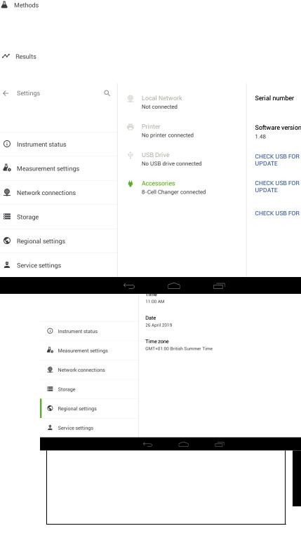
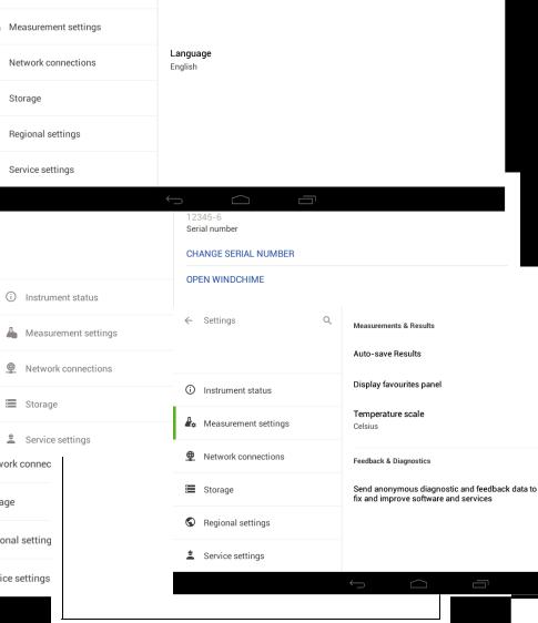
4.5Settings
Touch  to enable access to instrument status, measurement settings, network connections, storage and service settings.
4.5.1Instrument Status
Touch  to view the status of the spectrophotometer, check connections, fitted accessories, the serial number of the unit and the software version the instrument is using. The language and date and time can also be set here.
4.5.1.1 Instrument Language
The software can be viewed in five different languages with a choice of English, French, German, Spanish or
Italian. To select the required language touch |
and select from the menu. Touch |
next to the |
required language to apply. |
|
|
18
4.5.1.2 Setting the Time |
|
|
|
To set the instrument time touch |
Touch |
and move the clock hand |
to the correct hour position, |
repeat the same process for minutes, select AM or PM and touch  to apply. Touching
  will return to the instrument settings screen without altering the time. The set time will be displayed in each measurement mode and will be recorded against saved methods and results.
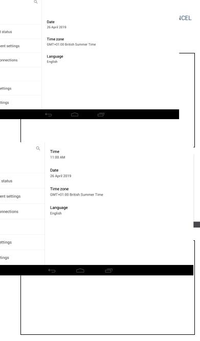
4.5.1.3 Setting the Date
To set the instrument date touch  Scroll up or down to change the month viewed. Touch the required date
  and touch
  to apply. To set the year touch
  and scroll up or down and touch the required date
  and touch
  to apply. Touching
  will return to the instrument settings screen
without altering the date. The set date will be displayed in each measurement mode and will be recorded against
19
4.5.1.4 Setting the Time Zone |
|
|
|
To set the instrument time zone touch |
. Scroll up or down to locate the required time |
||
zone and touch |
next to the required time zone to apply. |
|
|
|
|
|
|
|
|
|
|
4.5.2Measurement Settings
Touch  to select options for autosave results and the favourites panel. Results can be saved automatically to the instrument’s internal memory by sliding the
  button to the
  position. To view the favourites panel on the home screen slide the button to
  the
the position.
If auto-save is not selected, then results need to be saved manually. Refer to section 11.4 for more details.
20

4.5.3Network Connections
Touch  to view available network connections. Options include Ethernet (RJ-45), IP configuration, connection status and CPLive.
4.5.4Storage
Touch  to view the amount of available storage on the internal memory of the spectrophotometer. If a USB memory stick is inserted the amount of free space on the USB stick will also be shown.
4.5.5Service Settings
Service settings is for service engineers only
Touch  to view the serial number and options to change serial number and to open windchime.
21

Section 5 - Photometrics
The photometrics measurement mode enables simple measurements of absorbance and % transmittance to be performed. The sample is measured at one wavelength and at one point in time. There are no post measurement calculations available in this measurement mode. Touch the Photometrics icon on the main menu to enter this measurement mode.
5.1Method Set up
Thismeasurement mode isvery simple andthe only parameter which can be adjustedis the wavelength. Once the required wavelength has been entered a calibration can be performed.
5.1.1Selecting a Wavelength
To adjust the wavelength, touch |
and use the keypad to enter the required wavelength. Touch |
to apply the entered wavelength and return to the method set up.
22
5.2Calibration
The calibration must be performed at the same wavelength at which the sample will be measured. Insert a cuvette containing the blank solution into the sample chamber and close the instrument lid. Touch the  icon. This sets the instrument to zero absorbance
  and 100% transmittance
  . Once the calibration has been performed the
  icon becomes active and a sample can be measured.
5.3Sample Measurement
It is not possible to measure a sample before the instrument has been calibrated at the selected wavelength. Once the calibration has been performed the  icon becomes active and a sample can be measured. Remove the cuvette containing the blank solution and place a cuvette containing the sample to be measured in the sample holder. Close the instrument lid and touch the
  icon. Once the measurement is completed the photometric
result will be shown on the screen  . Subsequent samples can be measured in the same way. If the
wavelength is adjusted between sample measurements then the instrument must be calibrated again before more
23
 Loading...